CN1638010A - Color picture tube apparatus - Google Patents
Color picture tube apparatus Download PDFInfo
- Publication number
- CN1638010A CN1638010A CN200410103681.0A CN200410103681A CN1638010A CN 1638010 A CN1638010 A CN 1638010A CN 200410103681 A CN200410103681 A CN 200410103681A CN 1638010 A CN1638010 A CN 1638010A
- Authority
- CN
- China
- Prior art keywords
- elongated elements
- pair
- magnetic material
- colour display
- display tube
- Prior art date
- Legal status (The legal status is an assumption and is not a legal conclusion. Google has not performed a legal analysis and makes no representation as to the accuracy of the status listed.)
- Pending
Links
Images


Classifications
-
- H—ELECTRICITY
- H01—ELECTRIC ELEMENTS
- H01J—ELECTRIC DISCHARGE TUBES OR DISCHARGE LAMPS
- H01J29/00—Details of cathode-ray tubes or of electron-beam tubes of the types covered by group H01J31/00
- H01J29/46—Arrangements of electrodes and associated parts for generating or controlling the ray or beam, e.g. electron-optical arrangement
- H01J29/70—Arrangements for deflecting ray or beam
- H01J29/701—Systems for correcting deviation or convergence of a plurality of beams by means of magnetic fields at least
- H01J29/702—Convergence correction arrangements therefor
- H01J29/703—Static convergence systems
-
- H—ELECTRICITY
- H01—ELECTRIC ELEMENTS
- H01J—ELECTRIC DISCHARGE TUBES OR DISCHARGE LAMPS
- H01J2229/00—Details of cathode ray tubes or electron beam tubes
- H01J2229/56—Correction of beam optics
- H01J2229/568—Correction of beam optics using supplementary correction devices
- H01J2229/5681—Correction of beam optics using supplementary correction devices magnetic
- H01J2229/5682—Permanently magnetised materials, e.g. permanent magnets
Abstract
A bar-shaped element includes magnets at both ends and a magnetic material connecting the magnets to each other. One end in a major axis direction of the bar-shaped element is an N-pole, and the other end is an S-pole. A pair of bar-shaped elements sandwich a deflection yoke in a horizontal direction, with the major axis direction thereof being parallel to a vertical direction, and each of the bar-shaped elements is placed at a position between the end of a horizontal deflection coil on a phosphor screen side and a central position of a core in a tube axis direction, in such a manner that the magnetic poles at both ends are opposite to each other between the pair of bar-shaped elements. Because of this, PQH misconvergence is corrected without influencing power consumption at low cost by a simple method without using an auxiliary coil and a correction circuit, whereby satisfactory convergence can be realized.
Description
Technical field
The present invention relates to a kind of colour display tube dence, it is used to make a plurality of electrons beam deflecting of sending from a row formula electron gun and shows coloured image at a phosphor screen.
Background technology
Generally speaking, be used for making a plurality of electrons beam deflecting that send from a row formula electron gun and the color picture tube that demonstrates coloured image at a phosphor screen, the skew control magnet is placed near the top and the bottom of screen side of a deflection yoke, with the pincushion distortion of calibration grating upper and lower sides usually.In this case, when deflection angle becomes big, it is more flat that screen will become, needing to change design makes horizontal deflection magnetic field become more even, and magnet will increase the side effect of assembling, and therefore, the misconvergence of PQH will occur being called, in this misconvergence, R (red) vertical line moves right with respect to B (indigo plant) vertical line in the bight of grating.The PQH misconvergence only distributes and can not be eliminated by the winding that changes coil.
In order to proofread and correct above-mentioned misconvergence, the someone has proposed the bearing calibration of a coil of various uses, for example by using method that a saturable reactor winding provides a corrective loop (for example, see TOHKEMY 2001-23541 communique), use method (for example, seeing the special fair 7-31989 communique of Japan) and other similar approach of an ancillary coil.
On the other hand, the somebody has proposed to be used for by using the whole bag of tricks of magnet calibration electron beam trace.
Japanese kokai publication hei 10-241602 communique discloses a kind of color cathode-ray tube apparatus, wherein, a pair of rectangular body is placed like this, being about to a deflection yoke is clipped in the middle, each described rectangular body all comprises a plurality of magnet and magnetic materials with the short spacing arranged alternate, and it is vertically parallel with vertical direction, thereby, colorimetric purity can obtain proofreading and correct, and can not make the convergence variation.
And, opening clear 62-86650 communique also discloses a kind of color cathode-ray tube apparatus in fact in Japan, wherein, electron beam can obtain proofreading and correct at the misconvergence of both sides by place a magnet respectively in by each quadrant in four quadrants of trunnion axis and vertical axes division.
Yet there is following problem in the above-mentioned bearing calibration according to TOHKEMY 2001-23541 communique: can cause that owing to the corrective loop power consumption increases; Corrective loop itself can increase cost; And when using another corrective loop together, loop structure will complicate; And other problems.
In addition, there is following problem in the above-mentioned bearing calibration according to the special fair 7-31989 communique of Japan: ancillary coil can increase cost; The same with the reason in the TOHKEMY 2001-23541 communique, be used to drive the loop of ancillary coil and can cause that power consumption increases owing to have, thereby can cause that the loop cost increases; And when using another corrective loop together, loop structure will complicate; And other problems.
In addition, according to the real bearing calibration of opening clear 62-86650 communique of Japanese kokai publication hei 10-241602 communique and Japan, have following problem: the vertical line misconvergence (XH) on the trunnion axis can occur once more.
Summary of the invention
The present invention can solve the problems referred to above of prior art, its objective is provides a kind of colour display tube dence, wherein, the PQH misconvergence can be proofreaied and correct at low cost by straightforward procedure, and can not influence power consumption and reduce the XH misconvergence, do not use simultaneously ancillary coil and corrective loop again, thereby, can realize gratifying convergence.
To achieve these goals, colour display tube dence of the present invention comprises a deflection yoke, and described deflection yoke comprises a horizontal deflection coil, a vertical deflection coil and a magnetic core.Described colour display tube dence can make a plurality of electrons beam deflecting that send from a row formula electron gun by using described deflection yoke, and can demonstrate coloured image on phosphor screen.Described colour display tube dence also comprises a pair of elongated elements, and each described elongated elements all comprises a magnetic material and is arranged in magnet on the two ends of described magnetic material.End on the major axes orientation of each elongated elements in the described a pair of elongated elements is the N utmost point, and the other end is the S utmost point.Described a pair of elongated elements is clipped in the middle described deflection yoke in the horizontal direction, and the major axes orientation of elongated elements is parallel with vertical direction, and each elongated elements in the described a pair of elongated elements is on the position between the central part of the end of the described horizontal deflection coil that is placed on described fluorescence screen side on the picture tube axis direction by this way and described magnetic core, and the magnetic pole that promptly is positioned on the two ends of different elongated elements is opposite each other.
At this, the meaning of " magnetic pole that is positioned on the two ends of different elongated elements is opposite each other " is, for an elongated elements in the described a pair of elongated elements parallel with described vertical direction, the N utmost point on the one end is positioned at upside, the S utmost point on the other end is positioned at downside, and for another elongated elements, the S utmost point on the one end is positioned at upside, and the N utmost point on the other end is positioned at downside.
Just can obviously find out these and other advantages of the present invention during the detailed description below reading referring to accompanying drawing and having understood, done for the person of ordinary skill of the art.
Description of drawings
Fig. 1 is the perspective view of the deflection yoke of colour display tube dence according to an embodiment of the invention;
Fig. 2 is a schematic diagram, shows elongated elements on the described deflection yoke that is located at described colour display tube dence according to an embodiment of the invention, the magnetic line of force that is produced by described elongated elements and the power that influences electron beam;
Fig. 3 is a schematic diagram, shows the convergence of described colour display tube dence according to an embodiment of the invention;
Fig. 4 is a schematic diagram, shows the magnetic line of force and the power that influences electron beam under the situation of having used a pair of strip magnet;
Fig. 5 is a schematic diagram, shows the convergence under the situation of having used a pair of strip magnet;
Fig. 6 is a schematic diagram, shows the magnetic line of force and the power that influences electron beam under the situation of only using four magnets in that magnetic material is removed;
Fig. 7 is a schematic diagram, shows the convergence under the situation of only using four magnets in that magnetic material is removed; And
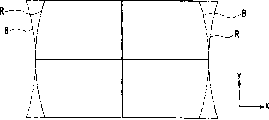
Fig. 8 is a schematic diagram, shows the PQH misconvergence in traditional colour display tube dence.
Embodiment
According to colour display tube dence of the present invention, can only mainly proofread and correct the PQH misconvergence in the following manner and the desirable magnetic field for correcting realizing being free from side effects substantially distributes: use magnetic material and the magnet that is connected on the two ends of described magnetic material forms an elongated elements and arranges a pair of described elongated elements expediently.Thereby the PQH misconvergence can be proofreaied and correct at low cost by comparatively simple method, and needn't use ancillary coil and corrective loop, and consumption can not increase electric power again simultaneously.
In described colour display tube dence of the present invention, preferably, when looking up in the side along the picture tube axis, the N utmost point on the two ends of described elongated elements and the S utmost point roughly be positioned on the fluoroscopic diagonal respectively.Specifically, preferably, when described elongated elements along described picture tube axis during to described phosphor screen projection, the N utmost point on their two ends and the S utmost point lay respectively on the described fluoroscopic diagonal of shape in the form of a substantially rectangular.According to this structure, the PQH misconvergence can utilize the magnetic force of the less magnet of number and be proofreaied and correct effectively, and don't can upset whole the convergence.
And, preferably, suppose that the length on the major axes orientation of described magnetic material is a, the length that is arranged on the major axes orientation of each magnet on the two ends of described magnetic material is b, then satisfies following relation: 2b<a<4b.According to this structure, can only proofread and correct the PQH misconvergence, thereby can suppress the appearance of XH misconvergence.
Below, referring to accompanying drawing embodiments of the invention are described.
Fig. 1 is a perspective view, shows a deflection yoke in the colour display tube dence according to an embodiment of the invention.From picture tube glass bulb cone (not shown) side, described deflection yoke comprises horizontal deflection coil 1 and vertical deflection coil 2 successively.In the reality, be provided with the resinous framework that they insulation are come between horizontal deflection coil 1 and the vertical deflection coil 2.Yet, omitted described resinous framework at this, to simplify view and to be clearly shown that each member.In addition, the periphery part of vertical deflection coil 2 is covered with magnetic core 3.At this, as shown in Figure 1, suppose that horizontal direction is the x axle, vertical direction is the y axle, the picture tube axis direction is the z axle.The forward that also can suppose the z axle is the direction from described deflection yoke to the phosphor screen (not shown).The structural similarity of said structure and traditional deflection yoke.
The invention is characterized in, a pair of elongated elements 4 be located in this wise magnetic core 3 near, promptly they are clipped in the middle magnetic core 3 on the x direction of principal axis.Although a pair of elongated elements 4 remains on the described resinous framework by means of a maintaining body, described maintaining body is owing to its structure can be selected arbitrarily to be omitted.To the concrete structure of described maintaining body without any particular restriction.For example, can use and be generally used for the skew control magnet is remained on the essentially identical maintaining body of maintaining body on the described resinous framework, such as, can adopt a kind of embedded system and a kind of connected system and other systems, in described embedded system, recessed capsule or passage embed shape and are formed on the described resinous framework, and elongated elements 4 is assemblied in described recessed capsule or passage embeds in the shape, in described connected system, one is used for the groove of adjusting position or the surface that protuberance is located at described resinous framework, and elongated elements 4 contacts with described groove or protuberance, to be fastened on described groove or the protuberance.
Described a pair of elongated elements 4 is made of the strip magnet 6 on a strip magnetic material 5 and a pair of two ends that are connected magnetic material 5 respectively.Pair of magnets 6 is connected on the magnetic material 5 like this, even the end on the major axes orientation of each elongated elements in a pair of elongated elements 4 is the N utmost point, the other end is the S utmost point.In the present invention, " magnet " is meant so-called permanent magnet, and it is a kind of material that can radiate the magnetic line of force with generation magnetic field, thereby, have for example character of iron of the magnetic material of attraction.In addition, in the present invention, " magnetic material " is meant a kind of absorption by the another kind of material material of the magnetic line of force in the magnetic field that produces of magnet for example, thereby, have and can magnetize temporarily to attracted to the character on the described magnet.In addition, a pair of elongated elements 4 is placed by this way, and promptly its major axes orientation is parallel to the y axle, and the magnetic pole on the two ends of each elongated elements 4 between a pair of elongated elements 4 is all opposite each other.On the z direction of principal axis, elongated elements 4 is placed on end position from the horizontal deflection coil 1 of fluorescence screen side to the interval of the center of magnetic core 3.
In addition, preferably, when the N utmost point on the two ends of elongated elements 4 and the S utmost point along described picture tube axis when described phosphor screen (or grating) is gone up projection, they roughly are positioned at respectively on the diagonal of the described phosphor screen (or grating) of shape in the form of a substantially rectangular.And, as shown in Figure 2, preferably, suppose that the length on the major axes orientation of magnetic material 5 is a, the length on the major axes orientation of a magnet 6 is b, then satisfies following relation: 2b<a<4b.
Except that being provided with above-mentioned a pair of elongated elements 4, the structure of described colour display tube dence of the present invention can with the structural similarity of traditional color picture tube.
Concrete example of the present invention
As more concrete design value, description is applied to have the example of wide CRT of the display screen diagonal size of 86cm.Length overall on the major axes orientation of elongated elements 4 is 85mm, and thickness (size on the z direction of principal axis) is 3mm, a=45mm, b=20mm.On the z direction of principal axis, a pair of elongated elements 4 is placed by this way, be that the surface that is positioned at described fluorescence screen side on each elongated elements 4 is consistent with the x-y plane of the end that is positioned at described fluorescence screen side on comprising magnetic core 3, on the x direction of principal axis, they be positioned on the x direction of principal axis apart from magnetic core 3 on the position of 10mm.The PQH correcting value can be by regulating the amount of magnetization of magnet 6 according to the generating capacity of PQH or regulating by connecting a magnetic shunt alloy.In this case, the thickness of each elongated elements 4 all can change; Yet this thickness can not impact effect.As the used material of elongated elements 4, ferrite is generally used for magnetic material 5.At this, be ferrite although can use Ni, also can use Mn is ferrite.As magnet 6, use magnet on sale on the market usually, and be connected on every end of magnetic material 5.Yet magnetic material 5 and magnet 6 also can form simultaneously by the ferritic two ends of strip are magnetized.
Effect of the present invention
Below, the effect that the PQH that is done by elongated elements 4 that describes is in the present invention proofreaied and correct.
Fig. 2 schematically shows the state of the magnetic line of force 7 of the influenced electron beam (not shown) from the magnetic line of force that described fluorescence screen side is produced by elongated elements 4 when described electron gun side is seen.And, also show the power 8 that can influence electron beam owing to the magnetic line of force 7.Can be clear that from Fig. 2 power 8 has in the bight electron beam (center of grating) effect of pushing back to the inside.This electron beam that acts on becomes stronger near magnetic pole (end) Shi Erhui of elongated elements 4.From described fluorescence screen side when described electron gun side is seen, the electron beam that passes deflection yoke being disposed in order by R (red), G (green) and B (indigo plant) usually from right to left on the x direction of principal axis.Therefore, in the right half part zone of described grating, compare with the B electron beam, the R electron beam more is subjected to the influence with its power that pushes back to the center of described grating, in the left-half zone of described grating, compare with the R electron beam, the B electron beam more is subjected to the influence with its power that pushes back to the center of described grating.Thereby PQH misconvergence as shown in Figure 8 can be corrected into as shown in Figure 3.
At this, for the effect of elongated elements 4 of the present invention further clearly is described, with the effect that is described under the situation of only using strip magnet 9 to substitute elongated elements 4.Fig. 4 schematically shows the magnetic line of force 7 that is produced by strip magnet 9 and the power 8 that influences electron beam in the mode identical with Fig. 2.Can be clear that from Fig. 4 strip magnet 9 has even all can be with electron beam (center of grating) effect of pushing back to the inside in the periphery of x axle and bight.Therefore, change as shown in Figure 5 can take place in the PQH misconvergence among Fig. 8.That is although the PQH misconvergence is only partly proofreaied and correct, also the XH misconvergence can appear.Therefore, misconvergence can not all be eliminated.In other words, R vertical line and the B vertical line that is arranged in the periphery on the x direction of principal axis only relatively moves on the x direction of principal axis.Unless PQH obtains proofreading and correct, otherwise can not realize that effective PQH proofreaies and correct under the situation that does not change XH.
Though described in the Japanese kokai publication hei 10-241602 communique and the similar a pair of rectangular body of the arrangement of the strip magnet 9 shown in Fig. 4, they comprise a plurality of magnet and magnetic materials with the short spacing arranged alternate, applying under the situation of the power similar to electron beam, the R vertical line of the periphery that is arranged on the x direction of principal axis and B vertical line are only relatively moved on the x direction of principal axis to the power of the strip magnet 9 shown in Fig. 4 by periphery at described bight and x axle.In addition, in Japanese kokai publication hei 10-241602 communique, in the zone that reduces by the interval between R electron beam and B electron beam (promptly, approaching in the described fluoroscopic zone with respect to described deflection yoke) a pair of rectangular body of placement, colorimetric purity can access correction, and can reduce the influence to misconvergence simultaneously.Therefore, a pair of rectangular body in the Japanese kokai publication hei 10-241602 communique does not have the PQH calibration result.
On the other hand, Japan opens the magnet structure described in the clear 62-86650 communique only uses four magnets 6 with in the present invention magnetic material 5 being removed structural similarity in fact.Fig. 6 schematically shows the magnetic line of force 7 that is produced by four magnets 6 and the power 8,10 and 11 that influences electron beam in the mode identical with Fig. 2.Can clearly be seen that from Fig. 6, owing to lack magnetic material 5, the magnetic flux that is arranged between two magnets 6 on the line parallel with the y direction of principal axis expands along the x direction of principal axis, and the magnetic flux that expands can produce the power 10 that can influence electron beam like this, can in the periphery of x axle electron beam be promoted laterally.In addition, the magnetic flux that points to S from the N utmost point of each described magnet can produce the power 11 that can influence electron beam like this, can near the periphery of x axle electron beam be drawn to x axle side draught.In other words, consider in the axial periphery of x along the variation of the power of the aspect effect electron beam parallel with the y axle, the power 8 that electron beam is pushed back to the inside results from the periphery, the power that laterally promotes electron beam 10 opposite with power 8 result from the x axle near, take place to the direction that the power 11 that x axle side draught draws electron beam results from this power counter-rotating part near.As mentioned above, the PQH misconvergence shown in Fig. 8 will become as shown in Figure 7.Specifically, the PQH misconvergence only obtains the part correction; On the other hand, in the right half part zone, the R vertical line moves in the periphery of x axle to the right, and in the left-half zone, the B vertical line moves in the periphery of x axle to the left, in this case, the XH misconvergence will take place.In addition, because the backward position place of the direction of power has produced power 11 between power 8 and 10, the PQV misconvergence in this case, can take place in the distortion that can deform of the R vertical line on right side and the B horizontal line in left side.Therefore, only use four magnets 6 can not all eliminate misconvergence.
According to the present invention, different with Fig. 4 to 7, only the PQH misconvergence can access effectively and proofread and correct, thereby is difficult to cause the XH misconvergence.According to this structure, PQH proofreaies and correct and can realize at an easy rate.Although XH can change a little according to the present invention, variable quantity is very little, and can obtain proofreading and correct by the winding distribution of regulating deflecting coil.
Application of the present invention is not particularly limited.For example, the present invention can be used as colour display tube dence, for example television receiver, computer display and similar device.Especially, the present invention under the situation that the PQH misconvergence takes place probably (for example, be made at screen flat, under the situation such as deflection angle increases and horizontal deflection magnetic field is even) colour display tube dence of design is very effective.
The present invention can otherwise realize under the situation that does not break away from its spirit or essential characteristic.The disclosed embodiments all should be thought exemplary, but not determinate in all respects in the application's book.Scope of the present invention limits by claims rather than by the description of front, this be included in that being equal to of claims carried out in the meaning and the scope change.
Claims (3)
1. colour display tube dence, comprise: deflection yoke, it comprises horizontal deflection coil, vertical deflection coil and magnetic core, and described colour display tube dence can make a plurality of electrons beam deflecting that send from a row formula electron gun by using described deflection yoke, and can on phosphor screen, demonstrate coloured image
Wherein, described colour display tube dence also comprises a pair of elongated elements, and each described elongated elements all comprises magnetic material and is arranged in magnet on the two ends of described magnetic material,
End on the major axes orientation of each elongated elements in the described a pair of elongated elements is the N utmost point, and the other end is the S utmost point, and
Described a pair of elongated elements is clipped in the middle described deflection yoke in the horizontal direction, and the major axes orientation of elongated elements is parallel with vertical direction, each elongated elements in the described a pair of elongated elements is being placed on described horizontal deflection coil in the following manner on the position between the central part of the end of described fluorescence screen side and described magnetic core on the picture tube axis direction, the magnetic pole that promptly is positioned on the two ends of different elongated elements is opposite each other.
2. colour display tube dence as claimed in claim 1 is characterized in that, the N utmost point on the two ends of described elongated elements and the S utmost point are when roughly being positioned at respectively on the described fluoroscopic diagonal when the picture tube axis is seen.
3. colour display tube dence as claimed in claim 1, it is characterized in that, suppose that the length on the major axes orientation of described magnetic material is a, the length that is arranged on the major axes orientation of each the described magnet on the two ends of described magnetic material is b, then satisfies following relation: 2b<a<4b.
Applications Claiming Priority (2)
| Application Number | Priority Date | Filing Date | Title |
|---|---|---|---|
| JP2003431105A JP2005190840A (en) | 2003-12-25 | 2003-12-25 | Color picture tube device |
| JP431105/2003 | 2003-12-25 |
Publications (1)
| Publication Number | Publication Date |
|---|---|
| CN1638010A true CN1638010A (en) | 2005-07-13 |
Family
ID=34545042
Family Applications (1)
| Application Number | Title | Priority Date | Filing Date |
|---|---|---|---|
| CN200410103681.0A Pending CN1638010A (en) | 2003-12-25 | 2004-12-24 | Color picture tube apparatus |
Country Status (4)
| Country | Link |
|---|---|
| US (1) | US20050140263A1 (en) |
| EP (1) | EP1548793A3 (en) |
| JP (1) | JP2005190840A (en) |
| CN (1) | CN1638010A (en) |
Families Citing this family (1)
| Publication number | Priority date | Publication date | Assignee | Title |
|---|---|---|---|---|
| JP2007128830A (en) * | 2005-11-07 | 2007-05-24 | Matsushita Toshiba Picture Display Co Ltd | Color cathode-ray tube device |
Family Cites Families (13)
| Publication number | Priority date | Publication date | Assignee | Title |
|---|---|---|---|---|
| KR910001401B1 (en) * | 1987-05-25 | 1991-03-04 | 미쯔비시덴끼 가부시끼가이샤 | Deflection yoke |
| DE69024789T2 (en) * | 1990-05-11 | 1996-09-19 | Thomson Tubes & Displays | Self-converging color picture tube system with large screen |
| JPH05182599A (en) * | 1991-12-26 | 1993-07-23 | Hitachi Ltd | Focus yoke, electromagnetic focus type crt display including it, and stray capacitor elimination type negative feedback circuit |
| SG46320A1 (en) * | 1993-02-18 | 1998-02-20 | Thomson Tubes & Displays | Deflection yoke with a forked shunt |
| JPH0799027A (en) * | 1993-08-05 | 1995-04-11 | Mitsubishi Electric Corp | Electron beam focusing device |
| FR2757678B1 (en) * | 1996-12-20 | 1999-01-29 | Thomson Tubes & Displays | DEVIATION UNIT FOR AUTOCONVERGENT CATHODIC RAY TUBE WITH SADDLE-SHAPED DEVIATION COILS |
| JPH10241602A (en) * | 1997-02-25 | 1998-09-11 | Toshiba Corp | Magnet for beam correction and color display device using the same |
| TW412056U (en) * | 1998-10-26 | 2000-11-11 | Koninkl Philips Electronics Nv | Picture display device comprising a deflection unit, and deflection unit for such a picture display device |
| JP2001023541A (en) * | 1999-07-12 | 2001-01-26 | Matsushita Electronics Industry Corp | Color picture tube device |
| TW480525B (en) * | 1999-12-22 | 2002-03-21 | Matsushita Electronics Corp | Color display tube device |
| JP2002289118A (en) * | 2001-03-27 | 2002-10-04 | Toshiba Corp | Color cathode-ray tube device |
| EP1378927A1 (en) * | 2002-07-04 | 2004-01-07 | Matsushita Display Devices (Germany) GmbH | Color display tube and deflection system with improved imaging properties |
| WO2004049381A1 (en) * | 2002-11-22 | 2004-06-10 | Matsushita Electric Industrial Co., Ltd. | Deflection yoke and catthode ray tube unit |
-
2003
- 2003-12-25 JP JP2003431105A patent/JP2005190840A/en active Pending
-
2004
- 2004-11-17 US US10/991,233 patent/US20050140263A1/en not_active Abandoned
- 2004-12-23 EP EP04258118A patent/EP1548793A3/en not_active Withdrawn
- 2004-12-24 CN CN200410103681.0A patent/CN1638010A/en active Pending
Also Published As
| Publication number | Publication date |
|---|---|
| EP1548793A2 (en) | 2005-06-29 |
| US20050140263A1 (en) | 2005-06-30 |
| EP1548793A3 (en) | 2005-07-06 |
| JP2005190840A (en) | 2005-07-14 |
Similar Documents
| Publication | Publication Date | Title |
|---|---|---|
| CA1124308A (en) | Deflection yoke with permanent magnet raster correction | |
| US4231009A (en) | Deflection yoke with a magnet for reducing sensitivity of convergence to yoke position | |
| US5378961A (en) | Deflection yoke apparatus | |
| CA1093625A (en) | Apparatus producing static eight-pole magnetic field for correcting raster distortion in a television picture tube | |
| US4654616A (en) | Blue bow correction for CRT raster | |
| CN1018873B (en) | Deflection yoke for use in colour cathode ray tube | |
| KR850001389B1 (en) | Deflection yoke for a color cathode ray tube | |
| EP0232948A1 (en) | Device for displaying television pictures and deflection unit therefor | |
| CN1638010A (en) | Color picture tube apparatus | |
| EP0997924B1 (en) | Color CRT with cross-misconvergence correction device | |
| JPS63261659A (en) | Display device having combination of display tube and deflection unit | |
| KR930010668B1 (en) | Deflection apparatus | |
| EP0797235B1 (en) | Compensating device for CRT raster distortion | |
| US6573668B1 (en) | Color cathode ray tube having a convergence correction apparatus | |
| EP1069763A3 (en) | Deflection correction circuit for color display tube | |
| JP2981148B2 (en) | Cathode ray tube device | |
| JP3334861B2 (en) | Deflection yoke | |
| JP3825212B2 (en) | Color picture tube device | |
| JP3003669B2 (en) | Convergence device with dynamic convergence adjustment device and dynamic convergence adjustment method | |
| KR20020040915A (en) | Display device comprising a deflection unit, and a deflection unit for a display device | |
| JP2001332189A (en) | Deflection yoke | |
| JPH10241602A (en) | Magnet for beam correction and color display device using the same | |
| JPH04106837U (en) | deflection yoke | |
| EP1503397A3 (en) | Color picture tube apparatus | |
| JP2004342543A (en) | Deflection yoke |
Legal Events
| Date | Code | Title | Description |
|---|---|---|---|
| C06 | Publication | ||
| PB01 | Publication | ||
| C10 | Entry into substantive examination | ||
| SE01 | Entry into force of request for substantive examination | ||
| C02 | Deemed withdrawal of patent application after publication (patent law 2001) | ||
| WD01 | Invention patent application deemed withdrawn after publication |