CN1255829C - Keyboard - Google Patents
Keyboard Download PDFInfo
- Publication number
- CN1255829C CN1255829C CNB021543607A CN02154360A CN1255829C CN 1255829 C CN1255829 C CN 1255829C CN B021543607 A CNB021543607 A CN B021543607A CN 02154360 A CN02154360 A CN 02154360A CN 1255829 C CN1255829 C CN 1255829C
- Authority
- CN
- China
- Prior art keywords
- key top
- keyboard
- cast gate
- semi
- layer
- Prior art date
- Legal status (The legal status is an assumption and is not a legal conclusion. Google has not performed a legal analysis and makes no representation as to the accuracy of the status listed.)
- Expired - Fee Related
Links
Images


Classifications
-
- H—ELECTRICITY
- H01—ELECTRIC ELEMENTS
- H01H—ELECTRIC SWITCHES; RELAYS; SELECTORS; EMERGENCY PROTECTIVE DEVICES
- H01H13/00—Switches having rectilinearly-movable operating part or parts adapted for pushing or pulling in one direction only, e.g. push-button switch
- H01H13/02—Details
- H01H13/12—Movable parts; Contacts mounted thereon
- H01H13/14—Operating parts, e.g. push-button
-
- H—ELECTRICITY
- H01—ELECTRIC ELEMENTS
- H01H—ELECTRIC SWITCHES; RELAYS; SELECTORS; EMERGENCY PROTECTIVE DEVICES
- H01H13/00—Switches having rectilinearly-movable operating part or parts adapted for pushing or pulling in one direction only, e.g. push-button switch
- H01H13/70—Switches having rectilinearly-movable operating part or parts adapted for pushing or pulling in one direction only, e.g. push-button switch having a plurality of operating members associated with different sets of contacts, e.g. keyboard
-
- H—ELECTRICITY
- H01—ELECTRIC ELEMENTS
- H01H—ELECTRIC SWITCHES; RELAYS; SELECTORS; EMERGENCY PROTECTIVE DEVICES
- H01H2219/00—Legends
- H01H2219/028—Printed information
-
- H—ELECTRICITY
- H01—ELECTRIC ELEMENTS
- H01H—ELECTRIC SWITCHES; RELAYS; SELECTORS; EMERGENCY PROTECTIVE DEVICES
- H01H2221/00—Actuators
- H01H2221/07—Actuators transparent
-
- H—ELECTRICITY
- H01—ELECTRIC ELEMENTS
- H01H—ELECTRIC SWITCHES; RELAYS; SELECTORS; EMERGENCY PROTECTIVE DEVICES
- H01H2229/00—Manufacturing
- H01H2229/044—Injection moulding
- H01H2229/047—Preformed layer in mould
-
- Y—GENERAL TAGGING OF NEW TECHNOLOGICAL DEVELOPMENTS; GENERAL TAGGING OF CROSS-SECTIONAL TECHNOLOGIES SPANNING OVER SEVERAL SECTIONS OF THE IPC; TECHNICAL SUBJECTS COVERED BY FORMER USPC CROSS-REFERENCE ART COLLECTIONS [XRACs] AND DIGESTS
- Y10—TECHNICAL SUBJECTS COVERED BY FORMER USPC
- Y10T—TECHNICAL SUBJECTS COVERED BY FORMER US CLASSIFICATION
- Y10T428/00—Stock material or miscellaneous articles
- Y10T428/24—Structurally defined web or sheet [e.g., overall dimension, etc.]
- Y10T428/24752—Laterally noncoextensive components
Landscapes
- Push-Button Switches (AREA)
Abstract
A key sheet having a key top made of resin, a translucent resin film provided over the key top and a symbol layer. The key top includes a gate corresponding section (G) in a position corresponded to a gate of a mold for injecting resin to form the key top. The symbol layer is disposed to associate with the top surface of the key top. The gate corresponding section (G) is located to prevent the gate corresponding section (G) from being viewed through the symbol layer.
Description
Technical field
The present invention relates to for example information communication device of multiple electronic application device, comprise portable phone, be used for the keyboard of push-button switch in automobile telephone and the acoustics.
Background technology
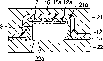
Various electronics apparatus comprise communication terminal for example portable phone and automobile telephone, all require littler weight, size and thickness.Therefore, the push-button switch that is used on these devices also requires littler size.In order to adapt to above-mentioned requirements, we know that in this technology keyboard has by semi-transparent resin and attached to its key top of forming except the semi-transparent resin film on all surface at the back side.Present this keyboard is widely used.
Figure 15 is the drawing in side sectional elevation of conventional keyboard.Keyboard 31 is by: key top 33, made by semi-transparent resin, and forms attached to the semi-transparent resin film 32 except the key top outer surface at the back side, so one or more convex shaped button 34 is formed on its upper surface.The back side 32a that symbol layer 35 is formed on semi-transparent resin film 32 with (for example letter, symbol, numeral and pattern) display graphics symbol on button 34.Graphic symbol is attached on the symbol layer 35 by printing or similar method.A traditional key top 33 comprises a cast gate correspondence 36a of portion, it with one to be used for 33a overleaf be that the cast gate of central position injection resin is corresponding basically.Usually, keyboard 31 is made like this: first curved translucent resin film 32 makes it have profile corresponding to key top 33, injection molding resin in sweep then.
At present, need carry out the design of various this keyboard.The design of the keyboard of various push-button switch that is used for portable phone for example, need be provided.Therefore, require keyboard to have high-quality structure, the graphic symbol that is presented on the keyboard can be clear and legible.
But the cast gate correspondence 36a of portion is arranged on the position corresponding to the cast gate of the mould that supplies injecting resin.Because cast gate correspondence portion is arranged on the middle position nearly of back side 33a on the key top 33 of conventional keyboard 31, when the upper surface observation key from button 34 pushes up 33, just can see the cast gate correspondence 36a of portion.Therefore, aforesaid conventional keyboard 31 is weak on its structure.Especially, be formed at symbol layer 35 under the situation on the back side 32a of semi-transparent resin film, the pattern of symbol layer 35 can be owing to the existence of the cast gate correspondence 36a of portion is out of shape.Like this, because the cast gate correspondence 36a of portion makes the observer can not be easy to observe symbol layer 35, the visibility of the button 34 of keyboard 31 will reduce.
In order to solve the above problems, people attempt in the periphery on key top 33 the cast gate correspondence 36a of portion being set, shown in the reference number 36b among Figure 15.But, when the cast gate correspondence 36a of portion only moves on to the edge of conventional keyboard structure, still can see the cast gate correspondence 36a of portion from the upper surface of the button 34 of keyboard.
On the other hand, the open communique 8-7698 of Japan Patent has disclosed a kind of keyboard 41, and as shown in figure 16, wherein the 46a of cast gate correspondence portion is set to outwards give prominence to from a side of the protuberance on key top 43.
But, when key top 43 is also will be from the minimum surface of semi-transparent resin film 42 outstanding,, just can not realize making the keyboard 41 that approaches because the thickness L of ledge 43a makes key top 43 become thicker.And when the key of making above-mentioned shape pushed up 43, it was very difficult the thermoplastic resin of fusing being filled with in the die cavity of mould.In this method, be easy to produce so-called injection deficiency, bubble etc.
Summary of the invention
The invention solves the problems referred to above.The purpose of this invention is to provide the keyboard with high-quality structure, it is little that it has size, advantage such as in light weight and high-visibility.
In order to achieve the above object, keyboard provided by the invention has the key top (13 that resin is made, 73), be arranged on semi-transparent resin film (12,72,122) and symbol layer (16 on the key top, 75,125), described key top is included in locational corresponding to for the mould gate that injects resin, to form a key top cast gate correspondence portion (G), described symbol layer (16,75,125) be arranged to upper surface combination with key top (13,73), it is characterized in that, described cast gate correspondence portion (G) is positioned at by symbol layer (16,75,125) can not be observed the place.
Other aspect and advantage of the present invention will be more apparent.Explanation is in conjunction with the drawings set forth in the mode of example principle of the present invention.
Description of drawings
With reference to following explanation, and in conjunction with the accompanying drawings, will understand the present invention and purpose and advantage better to most preferred embodiment.
Fig. 1 is the perspective view according to the keyboard of the first embodiment of the present invention;
Fig. 2 is the drawing in side sectional elevation of taking among 2-2 Fig. 1 along the line;
Fig. 3 is the drawing in side sectional elevation that is used to make the mould on key of the present invention top;
Fig. 4 is the part drawing in side sectional elevation that shows the process of the process of making keyboard of the present invention;
Fig. 5 is the perspective view according to the button of keyboard of the present invention;
Fig. 6 is the part drawing in side sectional elevation according to the keyboard of the first embodiment of the present invention;
Fig. 7 is the perspective view of keyboard according to a second embodiment of the present invention;
Fig. 8 is the drawing in side sectional elevation of taking among 8-8 Fig. 7 along the line;
Fig. 9 is the perspective view according to the key top that is made of semi-transparent resin in the keyboard of second embodiment;
Figure 10 is the drawing in side sectional elevation of mould that is used to make the key top of the second embodiment of the present invention;
Figure 11 is the drawing in side sectional elevation that shows the process of the process of making keyboard according to a second embodiment of the present invention;
Figure 12 is the perspective view of the keyboard of a third embodiment in accordance with the invention;
Figure 13 is the perspective view according to the key top that is made of semi-transparent resin in the keyboard of the 3rd embodiment;
Figure 14 is the part drawing in side sectional elevation of demonstration according to the process of the process of another method manufacturing keyboard;
Figure 15 is the part drawing in side sectional elevation that shows a kind of traditional keyboard;
Figure 16 is the part drawing in side sectional elevation that shows a kind of traditional keyboard.
Embodiment
Below with reference to Fig. 1-Fig. 5 the first embodiment of the present invention is described.
As shown in Figure 1, a plurality of buttons 14 are given prominence on the upper surface of keyboard 11.Keyboard 11 is made up of semi-transparent resin film 12 and a plurality of key top 13.Key top 13 is essentially cylindrical, and is made of semi-transparent resin.The part of semi-transparent resin film 12 is bent to the surface that is suitable for resin key top 13, and semi-transparent resin film 12 is attached on the surface except that the 13a of the back side on key top 13 like this.
More particularly, the example of semi-transparent resin film 12 can comprise the alkene film, vinyl film, fluoride film, polycarbonate film, acetate film, polyester film, polyamide film, polyimide film and ionomer films.Wherein, has the polycarbonate film of better translucence, fluoride film and polyester film the best.
First decorative layer 15 is arranged on the 12a place, the back side of contiguous semi-transparent resin film 12.First decorative layer 15 selectively only is arranged on some part of back side 12a of semi-transparent resin film 12.In fact an opening 15a is arranged on the central authorities of button 14.
First decorative layer 15 can have any color (comprise red, orchid, Huang, green, white, black and grey etc.) or it can have metallic luster.Can see first decorative layer 15 from the upper surface of button 14 by semi-transparent resin film 12.It pastes printing ink or tunic by applying, print, changeing on the 12a of the back side of semi-transparent resin film 12, evaporation or change and paste inorganic substances and form.It should be noted that first decorative layer 15 can show that any graphic symbol comprises letter, numeral, symbol and pattern.
By on some part of the back side of semi-transparent resin film 12 12a, forming first decorative layer 15, just opening 15a can be set.Perhaps, at first the whole back side 12a at semi-transparent resin film 12 forms first decorative layer 15, removes a part of first decorative layer 15 by modes such as etchings again, also opening 15a can be set.
In fact symbol layer 16 is arranged on the central authorities of opening 15a.Symbol layer 16 display graphics symbols comprise letter, numeral, and symbol and pattern can be seen these graphic symbols from the top of button 14 by semi-transparent resin film 12.Symbol layer 16 can be on the back side 12a of the semi-transparent resin film 12 in the opening 15a scope pastes printing ink or tunic by applying, print, changeing, evaporation or change and paste inorganic substances and form.Symbol layer 16 can be that characters cut in relief shows or characters cut in intaglio show.Symbol layer 16 can be formed on the upper surface or the back side of semi-transparent resin film 12, also can be not only at upper surface but also go up overleaf.
Transparent reinforced layer 17 is arranged on the back side of first decorative layer 15 and symbol layer 16.Reinforced layer 17 can be at the back side of first decorative layer 15 and symbol layer 16 by for example being to apply, print a transparent resin film to form.Reinforced layer 17 suppresses the distortion of first decorative layers 15 and symbol layer 16, be out of shape and degrade, and they also will stand the process of curved translucent resin molding 12 and form the process of the injection moulding on key top 13.By suppressing distortion, be out of shape and degrade the outward appearance and the quality that can keep first decorative layer 15 and symbol layer 16.Reinforced layer 17 has further improved the degree of adhesion between semi-transparent resin film 12 and the key top 13.
The synthetic resin that is used to make key top 13 to concrete composition, kind or color without limits, as long as it is translucent.Resin is that satisfactory performance can suitably be selected in existing synthetic resin, and these synthetic resin comprise thermoplastic resin, thermoplastic elastomer, hardening resin or cross-linked rubber.Easily manufactured thermoplastic resin is better.Spendable better material comprises: polycarbonate resin, mylar, fluoride resin, acrylic resin, acrylonitrile butadiene styrene resin (ABS resin), acrylonitrile styrene resin and propylene dichloride nitrile polyethylene-styrene resin.Polycarbonate resin is especially good, and it is in the transparency, and aspects such as mechanical strength and thermal endurance all have fine qualities.
One and in mould the cast gate correspondence G of portion of the cast gate correspondence of injecting resin be arranged on the back side 13a on key top 13.The cast gate correspondence G of portion is arranged on the following of first decorative layer 15 and near the neighboring of the back side 13a on key top 13, to avoid below opening 15a.More particularly, the cast gate correspondence G of portion can be arranged on the places that as shown in Figure 2 inhibition angle θ is equal to or less than 60 degree, suppresses angle θ promptly by the L shaped angle that becomes of the line stretcher of three in the corresponding portion with cast gate of horizontal line and edge of opening.Therefore, the back side 13a smooth surface on key top 13, in fact below the opening 15a that the center of button 14 is provided with without any step.Like this, high-quality letter and ornament can easily be set, so just can enough various method design buttons 14 by the visible zone of opening 15a.Therefore, keyboard 11 just can realize having better outward appearance.
Second decorative layer 18 is arranged on the back side 13a on key top 13.Second decorative layer 18 can have shades of colour (comprise red, orchid, Huang, green, white, black and grey etc.) or it can have metallic luster.Can see second decorative layer 18 from the upper surface of button 14 by semi-transparent resin film 12.Second decorative layer 18 can form with the method that is similar to first decorative layer 15.Second decorative layer 18 can show that any graphic symbol comprises letter, numeral, symbol and pattern.The cast gate correspondence G of portion be arranged on first decorative layer 15 below, and the neighboring of the back side 13a on adjacent keys top 13 is beyond recognition out the cast gate correspondence G of portion like this in the keyboard 11 according to first embodiment.Therefore, second decorative layer 18 can not darkened by the cast gate correspondence G of portion yet.Like this, keyboard 11 can realize having better outward appearance.Can be by aforesaid second decorative layer 18 is set further with various method design keyboards 11.
First decorative layer 15 and second decorative layer 18 preferably have metallic luster.First and second decorative layers 15 and 18 with such metallic luster can form by applying or print printing ink (metal ink) or the evaporation that contains metal dust or changeing the metal that pastes as aluminium, chromium, copper and mickel.Design with metallic luster can realize by making first and second decorative layers 15 and 18 have metallic luster.
First decorative layer 15 and second decorative layer 18 preferably have translucence.First and second decorative layers 15 and 18 can have translucence as the metal of aluminium, chromium, copper and mickel to the thickness between the 2-399nm by applying, print printing ink with translucence or tunic or evaporation.First and second decorative layers 15 and 18 have translucence, keyboard 11 at night or dark local visibility can be by on the back side 13a on key top 13, a light source being set, for example light-emitting diode (LED) and electroluminescence (EL) and be improved.By evaporating a kind of metal as aluminium, chromium, copper and mickel to the thickness between the 5-50nm, first and second decorative layers 15 and 18 can not only have metallic luster but also have translucence.
As mentioned above, when the upper surface observation key from button 14 pushes up 13, owing to the cast gate correspondence G of portion is can't see in the obstruct of first decorative layer 15 in the keyboard 11 of first embodiment.In other words, first decorative layer 15 has the function of covering the cast gate correspondence G of portion from the visual field.Therefore, keyboard 11 can have been realized better outward appearance.
First decorative layer 15 is arranged on the back side 12a of semi-transparent resin film 12, and graphic symbol layer 16 is arranged among the opening 15a, and second decorative layer 18 is arranged on the back side 13a on key top 13 of first embodiment.Is exactly visible by such formation button 14, the first and second decorative layers 15 and 18 around symbol layer 16, and symbol layer 16 presents the outward appearance of a three-dimensional projection, and wherein the shadow of the figure of symbol layer 16 is projected on second decorative layer 18.Impossible traditionally new design realizes making keyboard 11 can realize having better outward appearance by the symbol layer 16 that forms three-dimensional image.
The method that forms according to the keyboard 11 of first embodiment has been described with reference to figure 3 and 4.
The method that forms key top 13 with a pair of mould (first mould 21 and second mould 22) is described below.The die cavity S on moulded keys top 13 is provided in first mould 21 as shown in Figure 3.It is columniform hollow cavity 21a substantially that die cavity S is restricted to.
The centre that departs from die cavity S in second mould 22 is provided with cast gate 22a, for what go among the die cavity S that molten resin is expelled to first mould 21.Because cast gate correspondence portion is formed on the position that meets cast gate 22a, cast gate 22a is located at one and suppresses the place that the angle is equal to or less than, and suppresses the angle promptly by the L shaped angle that becomes of horizontal plane and edge of opening and the line stretcher between the cast gate 22a, is equal to or less than 60 and spends.The example of cast gate 22a comprises a cast gate, fan gate, film gate, circular gate, dish-shaped cast gate, the submarine gate, overlapping cast gate, drop gate, salient point cast gate and connor gate.Because the vestige cast gate correspondence G of portion of the cast gate that the some cast gate keeps on key top 13 is very little, so it is best, but cast gate specifically is not limited to such structure.
In the manufacturing of keyboard 11, first decorative layer 15 is formed on some part of back side 12a of semi-transparent resin film 12, and symbol layer 16 is formed among the opening 15a of first decorative layer 15 then.Transparent then reinforced layer 17 is formed on first decorative layer 15 and symbol layer 16 also on the side that forms on the semi-transparent resin film 12 at this place by the method that applies or print.
Form first decorative layer 15 thereon, symbol layer 16, and the semi-transparent resin film 12 of transparent reinforced layer 17 are clamped by locked mode between first and second moulds 21 and 22 as shown in Figure 4.Be clamped in the part of the semi-transparent resin film 12 between first and second half models 21 and 22 by locked mode, preferably be bent the shape (shape of the die cavity S of first mould 21) of distortion in advance with the upper surface on the key top 13 that is fit to moulding.This can accomplish with a kind of instrument such as clamping apparatus.
Rong Hua synthetic resin is injected into die cavity S by the cast gate 22a of second mould 22 then.Semi-transparent resin film 12 is extended opens the die cavity S shape much at one that bends to first mould 21, consistent to the injection among the die cavity S with the synthetic resin of fusing.As a result, semi-transparent resin film 12 and key top 13 adhere to each other by heat when key pushes up 13 moulding, and keyboard has just been made.
First and second moulds 21 and 22 are separated after cooling, to take out keyboard.Finish by on the back side 13a on the key top 13 of keyboard, forming second decorative layer, 18 backs according to the keyboard 11 of first embodiment.
Second decorative layer 18 can only be located on some part of back side 13a on key top 13.For example, second decorative layer 18 can only be formed on opening 15a under, as shown in Figure 6.
If insert film between semi-transparent resin film 12 and key top 13, first decorative layer can be located on the upper surface on key top 13.
The shape on key top 13 (forming the shape of the hollow cavity 21a on key top 13) can be an Any shape, no matter this shape has does not show in the drawings.
To Figure 11 the second embodiment of the present invention is described below in conjunction with Fig. 7.
As shown in Figure 7, a plurality of buttons 74 are arranged on the upper surface of keyboard 71.Keyboard 71 is made up of semi-transparent resin film 72 and a plurality of key top 73, as shown in Figure 8.The part of semi-transparent resin film 72 is bent to the surface that is suitable for key top 73, so that semi-transparent resin film 72 is attached to all surface except that the 73a of the back side of key 73.
Semi-transparent resin film 72 does not have the restriction of concrete composition, kind or color, as long as it is translucent.Resin can suitably be chosen from known synthetic resin meeting desired attribute of performance, and can use with the first embodiment similar methods and form.
Symbol layer 75 is arranged on the back side 72a of semi-transparent resin film 72 in the zone of button 74.Symbol layer 75 has shown graphic symbol, comprises letter, numeral, symbol and pattern, can see these graphic symbols from the top of button 74 by semi-transparent resin film 72.Symbol layer 75 is made by for example applying, print, change subsides printing ink or tunic on by the back side 72a of semi-transparent resin film 72.Symbol layer 75 can be that characters cut in relief shows or characters cut in intaglio.Symbol layer 75 can be formed on the upper surface or the back side of semi-transparent resin film 72, also can be not only at upper surface but also go up overleaf.
The synthetic resin that is used for key top 73 to concrete composition, kind or color without limits, as long as it is translucent.Resin can suitably be chosen from known synthetic resin meeting desired performance, and can with and first embodiment in similar methods form.
Shown in Fig. 7 to 9, key top 73 forms actual cylindrical, and protuberance 76 is arranged to from the outer surface outside protrusion radially on key top.Protuberance 76 forms the shape of flange along the whole circumference of the outer surface on key top 73.The back side 73a on key top 73 and the back side 76a of flange 76 form a continuous smooth surface, without any step.
Decorative layer 77 is arranged on the place of the back side 73a on adjacent keys top 73.Decorative layer 77 can have any color, comprises redness, blue look, yellow, green, white, black and grey or the like, perhaps also metallochrome can be arranged.Can see decorative layer 77 from the upper surface of button 74 through semi-transparent resin film 72.Decorative layer 77 can push up 73 back side 73a at key and paste printing ink or tunic by applying, print, changeing, perhaps evaporation or change and paste inorganic substances and make.Notice that decorative layer 77 can show any graphic symbol, comprise letter, numeral, symbol and pattern.
Decorative layer 77 preferably has metallic luster.Have the decorative layer 77 of metallic luster like this or to print the printing ink (metal ink) that contains metal dust by coating, perhaps evaporation or commentaries on classics are pasted and are formed as aluminium, chromium, copper, nickel or the like metal.The design that has metallic luster can realize by metallic luster being offered decorative layer 77.Like this, keyboard 71 just can be realized high-quality design.
Decorative layer 77 is preferably translucent.Decorative layer 77 can be by applying or print the printing ink or the tunic of translucence, perhaps by becoming the thickness between the 2-300nm to make translucent as the evaporation of metal of aluminium, chromium, copper, nickel or the like.Manufacture under the translucent situation at decorative layer 77, by on the back side 73a on key top 73 light source being set, as Light-Emitting Diode (LED) and electroluminor (EL), keyboard 71 will be improved at the visibility at night and dark place.By will become as the evaporation of metal of aluminium, chromium, copper, nickel or the like 5 and 50nm between thickness, decorative layer 77 can be realized metallic luster and translucent simultaneously.
The exhaust duct counterpart F of the cast gate correspondence G of portion of the cast gate of a corresponding mould and the exhaust duct of a corresponding mould is located at the back side 76a of flange 76 respectively.By like this, on the 76a of the back side of flange, form cast gate correspondence G of portion and the exhaust duct correspondence F of portion, the back side 73a on key top 73 can form the smooth surface without any step.
The cast gate correspondence G of portion is invisible when the upper surface of the button 74 from the keyboard 71 of second embodiment is observed.Equally, the G of cast gate correspondence portion can not become the reason that reduces symbol layer 75 visibilities.Therefore from the upper surface of button 74, symbol layer 75 can make keyboard 71 that better outward appearance is arranged.Keyboard 71 can be by the design that is provided with various different modes of symbol layer 75.
73 form thick films for fear of key top, just make the back side 73a on key top 73 form flat surfaces without any step.Equally, thin keyboard 71 just can not made 8-7698 number disclosed keyboard of publication communique of imaging Japan.In addition, since the back side 73a on key top 73 can manufacture the smooth surface without any step, so various characters and decoration just can be easily positioned on the back side 73a on key top 73.Therefore just can produce keyboard 71 with good outward appearance.
Be used for the cast gate correspondence G of portion of resin injection and the position that the exhaust duct correspondence F of portion lays respectively at 180 degree opposition, inserted key top 73 between the two.Therefore, the gas that produces among the die cavity S during the injection on moulded keys top 73 can be discharged to the outside by exhaust duct 102b (as shown in figure 10) effectively.Therefore the synthetic resin of fusing can be full of die cavity S, easily produces a keyboard 71 that good outward appearance is arranged.
Symbol layer 75 is provided with on the back side 72a of semi-transparent resin film 72 in a second embodiment, and decorative layer 77 is arranged on the back side 73a on key top 73.The shade of the figure of symbol layer 75 is incident upon on the decorative layer 77, and decorative layer 77 just can present the outward appearance of three-dimensional projection like this.Conventional method can not realize that new design can realize making keyboard 71 can realize having good outward appearance.
According to the keyboard 71 of second embodiment, will describe by reference Figure 10 and 11 below.The manufacture method on a kind of use a pair of mould (first mould 101 and second mould 102) moulded keys top 73 is described below.
A molded hollow cavity 101a (having the practical columnar shape that is used for moulded keys top 73) and a molded hollow cavity 101b (flange 76 that is used for molded practical columnar shape) have been positioned to same central shaft, have the cylinder die cavity S of step with qualification.
The cast gate 102a and the exhaust duct 102b that are used for injecting molten resin are formed on second mould 102.Cast gate 102a and exhaust duct 102b are separately positioned on the position of the molded hollow cavity 101b of relative first mould 101, and by the die cavity S that inserts first mould 101 relative to each other.
Though cast gate 102a is not subjected to the restriction of similar first embodiment, because it is very little to be retained in the vestige (the cast gate correspondence G of portion) of the cast gate on the key top 73, so the some cast gate is best.And the gap of exhaust duct 102b is preferably in 0.01mm between the 0.03mm.
Make in the process of keyboard 71, at first form symbol layer 75 on the 72a of the back side of semi-transparent resin film 72, semi-transparent resin film 72 is clamped between first and second moulds 101 and 102 by locked mode then.Semi-transparent resin film 72 is clamped at that part between first and second moulds 101 and 102, preferably by curve the shape (shape of the die cavity S of first mould 101) corresponding to the outside on key top 73 in advance with a kind of instrument such as clamping apparatus, key top 73 will be shaped in next step.
Rong Hua synthetic resin is injected into die cavity S by the cast gate 102a of second mould 102 then.Semi-transparent resin film 72 is extended opens the die cavity S shape much at one that bends to first mould 101, consistent to the injection among the die cavity S with the synthetic resin of fusing.Here, the gas that produces among the die cavity S in the forming process on key top 73 can be discharged into the outside of die cavity S by exhaust duct 102b, and therefore the synthetic resin of fusing can be filled among the die cavity S equably.As a result, semi-transparent resin film 72 and key top 73 adhere to each other by heat in key top 73 and flange 76 moulding simultaneously, and keyboard 71 has just been made then.
First and second moulds 101 and 102 are separated after cooling, to take out keyboard 71.Finish by on the back side 73a on the key top 73 of keyboard, forming decorative layer 77 according to the keyboard 71 of second embodiment.The cast gate correspondence G of portion will can not cover the sight line zone during character on seeing decorative layer 77.Therefore, can be clear that decorative layer 77 from the upper surface of the button 74 of keyboard 71, to realize that keyboard 71 has better outward appearance.By decorative layer 77 is set like this, can design keyboards 71 with various methods.
Concerning the person skilled in the art, the present invention can implement with multiple other concrete forms under the situation that does not break away from the spirit and scope of the present invention.Especially, the present invention can implement and make sense with following form.
The shape of key top 73 and flange 76, the shape of the molded hollow cavity 101b of the shape of the molded hollow cavity 101a on moulded keys top 73 and formation flange 76 can be by appropriate change.
Next with reference to Figure 12 and 13 third embodiment of the present invention is described.Only describe the special construction among the 3rd embodiment below the attention, no longer repeat the ordinary circumstance among second embodiment.
Shown in Figure 12 and 13, actual is that the lowermost portion of outer surface on columniform key top 123 is radially outward outstanding for the reality of columniform protuberance 128 and 129 in keyboard 121.By inserting key top 123, protuberance 128 and 129 is oppositely arranged respectively.The back side 123a on key top 123 and the back side 128a and the 129a of protuberance 128 and 129 form smooth surface without any step.
The cast gate correspondence G of portion on key top 123 is located on the back side 128a of protuberance 128.And the exhaust duct correspondence F of portion is located on the back side 129a of protuberance 129.Therefore, in the present embodiment, cast gate correspondence G of portion and the exhaust duct correspondence F of portion are oppositely arranged by inserting key top 13.
Therefore, can obtain being similar to the advantage of embodiment 2.
Example
Describe the second and the 3rd embodiment in detail below with reference to example.But the present invention is not limited by following Example.
Example 1
Form the symbol layer 75 that shows numerical chracter by printing black tunic on the back side of the semi-transparent resin film 72 that constitutes by polyethylene terephthalate.Push semi-transparent resin film 72 by a clamping apparatus then and make it crooked, so that semi-transparent resin film 72 forms and the corresponding shape of profile on key top 73.
Next, the semi-transparent resin film 72 through pushing is clamped between as shown in figure 11 first mould 101 and second mould 102 by locked mode.Then,, the cast gate 102a that is used for the resin injection that passes through to second mould 102 is injected into die cavity S with polycarbonate resin, integrally forms as shown in Figure 8 key top 73 and flange 76.In injection, by the fusing bonding on semi-transparent resin film 72 and key top 73, keyboard 71 has just been made.
Shown in Fig. 8 and 9, finish keyboard 71 by on the back side 73a on key top 73, printing white tunic formation decorative layer 77.The back side 73a on the key top 73 of keyboard 71 is smooth, without any step, so the outward appearance on key top 73 is better.
In according to the button 74 of the keyboard 71 of example 1, can see white in finish layer 77 around the black symbols layer 75.The shadow of black symbols layer 75 is projected onto white in finish layer 77, so symbol layer 75 presents the effect just like the three-dimensional projection.
Example 2
Tunic by the pattern of a phone of demonstration of a redness of printing on the 122a of the back side of semi-transparent resin film 122 forms symbol layer 125, and this semi-transparent resin film 122 is made up of the condensate alloy material and the polybutyleneterephthalate resin of polycarbonate.Then, push with curved translucent resin film 122 so that it forms the shape corresponding to the profile on key top 123 with a clamping apparatus.
Next, the semi-transparent resin film 122 through pushing is clamped between as shown in figure 14 first mould 141 and second mould 142 by locked mode.Then, with example 1 similarly, the cast gate 142a by second mould 142 is injected into polycarbonate resin among the die cavity S.In key 123 and ledge 128 and the 129 integrally formed whiles as shown in figure 13, by the fusing bonding on semi-transparent resin film 122 and key top 123, keyboard 121 has just been made.On the back side 123a on key top 123, paste the translucent aluminium paillon foil, form decorative layer 77, make keyboard 121 as shown in figure 12 at last by adding drop stamping.The keyboard 121 that is shaped has key top 123, and the back side 123a smooth surface on key top 123 is without any step.This has just obtained having the key top 123 of excellent appearance.
In the button 124 of the keyboard 121 of example 2, around red symbols layer 125, can see decorative layer 77 with silver metal gloss.The shadow of red symbols layer 125 is projected onto on the silver-colored decorative layer 77, so symbol layer 125 presents the effect just like the three-dimensional projection.
Therefore, should think above-mentioned example and embodiment be for explanation nonrestrictive.The details that the present invention does not also provide by this paper is limited, but the scope of attached claim and etc. can be modified in the same domain.
Claims (7)
1, a kind of keyboard, has the key top (13 that is formed from a resin, 73), be arranged on the semi-transparent resin film (12 of top, key top, 72,122) and symbol layer (16,75,125), described key top comprises one corresponding to injecting the locational cast gate correspondence portion (G) of cast gate of the mould of resin, described symbol layer (16,75 for forming the key top, 125) be arranged to and key top (13,73) upper surface combines, and it is characterized in that, described key top has the smooth surface without any step, described cast gate correspondence portion (G) is positioned at the neighboring of the back side on key top near the described back side, so that can not passing through symbol layer (16,75,125), cast gate correspondence portion (G) is observed.
2, keyboard as claimed in claim 1, it is characterized in that, further comprise one first decorative layer (15) that is arranged between semi-transparent resin film (12) and the key top (13), wherein first decorative layer (15) has an opening (15a) at the upper surface of key top (13), and cast gate correspondence portion (G) be arranged on described first decorative layer (15) below.
3, a kind of keyboard, comprise the key top (13) that is formed from a resin, the semi-transparent resin film (12) that is provided with is gone up on key top (13), symbol layer (16) and first decorative layer (15), described key top (13) comprises one corresponding to injecting the mould (21 of resin for forming the key top, the locational cast gate correspondence portion (G) of cast gate 22) (22a), described symbol layer (16) is arranged to combine with the upper surface on key top (13), described first decorative layer (15) is arranged between semi-transparent resin film (12) and the key top (13), wherein key top (13) has an opening (15a), this opening is formed on first decorative layer (15) on key top (13) and goes up the symbol layer (16) that combines with key top (13) to be provided with, it is characterized in that, described key top has the smooth surface without any step, described cast gate correspondence portion (G) be arranged on the following of described first decorative layer (15) and at the back side on described key top near the neighboring at the described back side, so that described cast gate correspondence portion (G) can not pass through symbol layer (16) is in sight.
As claim 1 or 3 described keyboards, it is characterized in that 4, cast gate correspondence portion (G) is arranged on by the line stretcher between 2 in the corresponding portion with cast gate in edge (G) of horizontal line and opening (15a) and forms on the position of the angles that are equal to or less than 60 degree.
5, as claim 1 or 3 described keyboards, it is characterized in that, further comprise one second decorative layer (18,77), its be arranged on key top (13,73) the back side (13a, 73a) on.
6, keyboard as claimed in claim 5 is characterized in that, has metallic luster at least one of in the first (15) and second (18,77) decorative layer.
7, as claim 1 or 3 described keyboards, it is characterized in that, symbol layer (16,75,125) be located at semi-transparent resin film (12,72,122) the back side (12a, 72a, 122a).
Applications Claiming Priority (4)
| Application Number | Priority Date | Filing Date | Title |
|---|---|---|---|
| JP2001362808A JP4087596B2 (en) | 2001-11-28 | 2001-11-28 | Film integrated key sheet |
| JP2001362808 | 2001-11-28 | ||
| JP2001364636A JP3961271B2 (en) | 2001-11-29 | 2001-11-29 | Film integrated key sheet |
| JP2001364636 | 2001-11-29 |
Publications (2)
| Publication Number | Publication Date |
|---|---|
| CN1421885A CN1421885A (en) | 2003-06-04 |
| CN1255829C true CN1255829C (en) | 2006-05-10 |
Family
ID=26624741
Family Applications (1)
| Application Number | Title | Priority Date | Filing Date |
|---|---|---|---|
| CNB021543607A Expired - Fee Related CN1255829C (en) | 2001-11-28 | 2002-11-27 | Keyboard |
Country Status (4)
| Country | Link |
|---|---|
| US (1) | US6967056B2 (en) |
| EP (1) | EP1316978B1 (en) |
| CN (1) | CN1255829C (en) |
| DE (1) | DE60221486T2 (en) |
Families Citing this family (41)
| Publication number | Priority date | Publication date | Assignee | Title |
|---|---|---|---|---|
| DE60221486T2 (en) * | 2001-11-28 | 2008-04-10 | Polymatech Co. Ltd. | key sheet |
| JP4017902B2 (en) * | 2002-03-29 | 2007-12-05 | ポリマテック株式会社 | Film integrated key top |
| DE10339842B4 (en) * | 2003-08-29 | 2008-02-14 | Angell-Demmel Europe Gmbh | Method of making buttons, ornamental and instrument panels with fine symbolism and a button made by the method |
| US7914869B2 (en) | 2005-04-18 | 2011-03-29 | Avery Dennison Corporation | Mobile device label with negative image feature |
| US7105759B1 (en) * | 2005-06-28 | 2006-09-12 | Tektronix, Inc. | Instrument with illuminated control knob |
| US7326870B2 (en) * | 2005-08-04 | 2008-02-05 | Silitech Technology Corp. | Key module and manufacturing method thereof |
| CN101276698B (en) * | 2007-03-28 | 2010-11-10 | 毅嘉科技股份有限公司 | Method for preparing thin type press key panel |
| US20090027339A1 (en) * | 2007-07-26 | 2009-01-29 | Doczy Paul J | Computing device pointing stick assembly |
| US8132976B2 (en) * | 2007-12-05 | 2012-03-13 | Microsoft Corporation | Reduced impact keyboard with cushioned keys |
| US8023261B2 (en) | 2008-09-05 | 2011-09-20 | Apple Inc. | Electronic device assembly |
| US8500348B2 (en) * | 2008-11-24 | 2013-08-06 | Logitech Europe S.A. | Keyboard with ultra-durable keys |
| EP2269795B1 (en) * | 2009-06-09 | 2013-07-31 | Abatek International AG | Process of manufacturing a membrane keypad and membrane keypad |
| CN101930861A (en) * | 2009-06-25 | 2010-12-29 | 深圳富泰宏精密工业有限公司 | Making method of key panel and key panel made by same |
| CN101930862A (en) * | 2009-06-26 | 2010-12-29 | 深圳富泰宏精密工业有限公司 | Manufacturing method of keypad panel and keypad panel manufactured therewith |
| TW201104718A (en) * | 2009-07-23 | 2011-02-01 | Ichia Tech Inc | Method of fabricating keycaps |
| US8797721B2 (en) | 2010-02-02 | 2014-08-05 | Apple Inc. | Portable electronic device housing with outer glass surfaces |
| US9235240B2 (en) | 2010-11-11 | 2016-01-12 | Apple Inc. | Insert molding around glass members for portable electronic devices |
| US9182789B2 (en) * | 2011-03-01 | 2015-11-10 | Apple Inc. | Transparent electronic device components with opaque edge coverings |
| US9354748B2 (en) | 2012-02-13 | 2016-05-31 | Microsoft Technology Licensing, Llc | Optical stylus interaction |
| US9158383B2 (en) | 2012-03-02 | 2015-10-13 | Microsoft Technology Licensing, Llc | Force concentrator |
| USRE48963E1 (en) | 2012-03-02 | 2022-03-08 | Microsoft Technology Licensing, Llc | Connection device for computing devices |
| US9426905B2 (en) | 2012-03-02 | 2016-08-23 | Microsoft Technology Licensing, Llc | Connection device for computing devices |
| US8935774B2 (en) | 2012-03-02 | 2015-01-13 | Microsoft Corporation | Accessory device authentication |
| US8873227B2 (en) | 2012-03-02 | 2014-10-28 | Microsoft Corporation | Flexible hinge support layer |
| US9360893B2 (en) | 2012-03-02 | 2016-06-07 | Microsoft Technology Licensing, Llc | Input device writing surface |
| US9075566B2 (en) | 2012-03-02 | 2015-07-07 | Microsoft Technoogy Licensing, LLC | Flexible hinge spine |
| US9870066B2 (en) | 2012-03-02 | 2018-01-16 | Microsoft Technology Licensing, Llc | Method of manufacturing an input device |
| US9064654B2 (en) | 2012-03-02 | 2015-06-23 | Microsoft Technology Licensing, Llc | Method of manufacturing an input device |
| US20130300590A1 (en) | 2012-05-14 | 2013-11-14 | Paul Henry Dietz | Audio Feedback |
| US10031556B2 (en) | 2012-06-08 | 2018-07-24 | Microsoft Technology Licensing, Llc | User experience adaptation |
| US9019615B2 (en) | 2012-06-12 | 2015-04-28 | Microsoft Technology Licensing, Llc | Wide field-of-view virtual image projector |
| US8964379B2 (en) | 2012-08-20 | 2015-02-24 | Microsoft Corporation | Switchable magnetic lock |
| US9304549B2 (en) | 2013-03-28 | 2016-04-05 | Microsoft Technology Licensing, Llc | Hinge mechanism for rotatable component attachment |
| US9871898B2 (en) | 2013-05-08 | 2018-01-16 | Apple Inc. | Ceramic cover for electronic device housing |
| US10120420B2 (en) | 2014-03-21 | 2018-11-06 | Microsoft Technology Licensing, Llc | Lockable display and techniques enabling use of lockable displays |
| US10324733B2 (en) | 2014-07-30 | 2019-06-18 | Microsoft Technology Licensing, Llc | Shutdown notifications |
| US9424048B2 (en) | 2014-09-15 | 2016-08-23 | Microsoft Technology Licensing, Llc | Inductive peripheral retention device |
| KR101876017B1 (en) * | 2016-04-29 | 2018-07-06 | 현대자동차주식회사 | Emergency lamp switch manufacturing method |
| KR101707789B1 (en) * | 2017-01-20 | 2017-02-20 | 주식회사 우신엠에스 | Apparatus for manufacturing light emitting metal knob |
| US10843066B2 (en) * | 2018-06-27 | 2020-11-24 | Facebook Technologies, Llc | Capacitive sensing assembly for detecting proximity of user to a controller device |
| CN113161183A (en) * | 2020-01-22 | 2021-07-23 | 东莞市旭优塑胶科技有限公司 | Film type luminous key |
Family Cites Families (10)
| Publication number | Priority date | Publication date | Assignee | Title |
|---|---|---|---|---|
| JP3211127B2 (en) * | 1994-06-23 | 2001-09-25 | 帝国通信工業株式会社 | Key top plate for push button switch |
| JP3101859B2 (en) * | 1994-12-05 | 2000-10-23 | 帝国通信工業株式会社 | Manufacturing method of key top plate |
| US5681515A (en) * | 1996-04-12 | 1997-10-28 | Motorola, Inc. | Method of fabricating an elastomeric keypad |
| JPH10289633A (en) * | 1997-04-15 | 1998-10-27 | Polymertech Kk | Trimmed light transmissive key top and manufacture thereof |
| US5911317A (en) * | 1997-08-26 | 1999-06-15 | Silitek Corporation | Light permeable metal plated rubber key |
| US6111324A (en) * | 1998-02-05 | 2000-08-29 | Asat, Limited | Integrated carrier ring/stiffener and method for manufacturing a flexible integrated circuit package |
| JP3204951B2 (en) * | 1999-05-24 | 2001-09-04 | ポリマテック株式会社 | Key sheet and manufacturing method thereof |
| JP2001250452A (en) * | 2000-03-06 | 2001-09-14 | Polymatech Co Ltd | Key seat |
| DE60221486T2 (en) * | 2001-11-28 | 2008-04-10 | Polymatech Co. Ltd. | key sheet |
| JP4017902B2 (en) * | 2002-03-29 | 2007-12-05 | ポリマテック株式会社 | Film integrated key top |
-
2002
- 2002-11-22 DE DE60221486T patent/DE60221486T2/en not_active Expired - Lifetime
- 2002-11-22 EP EP02445159A patent/EP1316978B1/en not_active Expired - Lifetime
- 2002-11-25 US US10/303,338 patent/US6967056B2/en not_active Expired - Fee Related
- 2002-11-27 CN CNB021543607A patent/CN1255829C/en not_active Expired - Fee Related
Also Published As
| Publication number | Publication date |
|---|---|
| DE60221486T2 (en) | 2008-04-10 |
| US20030108720A1 (en) | 2003-06-12 |
| US6967056B2 (en) | 2005-11-22 |
| EP1316978B1 (en) | 2007-08-01 |
| CN1421885A (en) | 2003-06-04 |
| EP1316978A1 (en) | 2003-06-04 |
| DE60221486D1 (en) | 2007-09-13 |
Similar Documents
| Publication | Publication Date | Title |
|---|---|---|
| CN1255829C (en) | Keyboard | |
| CN1243632C (en) | Injection-moulded decorative product and its production method | |
| CN100342763C (en) | Outer case of portable device | |
| JP4017902B2 (en) | Film integrated key top | |
| CN1255269C (en) | Decorative structure | |
| CN1990270A (en) | Decorative molded body, key top and key sheet for the pushbutton switch | |
| CN1305203A (en) | Push button top end parts of button switch and its manufacturing method | |
| KR20070084241A (en) | Decorated molding and method for producing the same | |
| CN1608301A (en) | Key sheet member and its production method | |
| CN1822941A (en) | In-mold decorated molded product and method of manufacturing the same | |
| CN1961394A (en) | Key unit with casing | |
| JP2007518219A (en) | Flexible molded EL lamp | |
| CN1494035A (en) | Sheet moulding shell | |
| JP3591719B2 (en) | Printed sheet for molding and key top member for push button switch | |
| JP2001084863A (en) | Sheet-shaped key top | |
| JP2008030266A (en) | Decorative sheet and decorative molding | |
| KR101511524B1 (en) | Manufactaring method of logo label | |
| JP2010030053A (en) | Illumination type panel and its manufacturing method | |
| JP4964276B2 (en) | Decorative body and method of manufacturing the decorative body | |
| JP4087596B2 (en) | Film integrated key sheet | |
| JP7017235B2 (en) | Manufacturing method of light emitting device and light emitting member | |
| JP3961271B2 (en) | Film integrated key sheet | |
| JP3144786U (en) | Electronic device shell | |
| JP2006130774A (en) | Decorative sheet for molding and molding with decoration | |
| CN1575955A (en) | Synthetic resin forming product and producing method thereof |
Legal Events
| Date | Code | Title | Description |
|---|---|---|---|
| C06 | Publication | ||
| PB01 | Publication | ||
| C10 | Entry into substantive examination | ||
| SE01 | Entry into force of request for substantive examination | ||
| C14 | Grant of patent or utility model | ||
| GR01 | Patent grant | ||
| C17 | Cessation of patent right | ||
| CF01 | Termination of patent right due to non-payment of annual fee |
Granted publication date: 20060510 Termination date: 20121127 |