CN1255385A - S-shaped ladder wound dilator - Google Patents
S-shaped ladder wound dilator Download PDFInfo
- Publication number
- CN1255385A CN1255385A CN99118499A CN99118499A CN1255385A CN 1255385 A CN1255385 A CN 1255385A CN 99118499 A CN99118499 A CN 99118499A CN 99118499 A CN99118499 A CN 99118499A CN 1255385 A CN1255385 A CN 1255385A
- Authority
- CN
- China
- Prior art keywords
- dilator
- bar
- side bands
- snakelike
- knee
- Prior art date
- Legal status (The legal status is an assumption and is not a legal conclusion. Google has not performed a legal analysis and makes no representation as to the accuracy of the status listed.)
- Pending
Links
Images


Classifications
-
- A—HUMAN NECESSITIES
- A61—MEDICAL OR VETERINARY SCIENCE; HYGIENE
- A61F—FILTERS IMPLANTABLE INTO BLOOD VESSELS; PROSTHESES; DEVICES PROVIDING PATENCY TO, OR PREVENTING COLLAPSING OF, TUBULAR STRUCTURES OF THE BODY, e.g. STENTS; ORTHOPAEDIC, NURSING OR CONTRACEPTIVE DEVICES; FOMENTATION; TREATMENT OR PROTECTION OF EYES OR EARS; BANDAGES, DRESSINGS OR ABSORBENT PADS; FIRST-AID KITS
- A61F2/00—Filters implantable into blood vessels; Prostheses, i.e. artificial substitutes or replacements for parts of the body; Appliances for connecting them with the body; Devices providing patency to, or preventing collapsing of, tubular structures of the body, e.g. stents
- A61F2/82—Devices providing patency to, or preventing collapsing of, tubular structures of the body, e.g. stents
- A61F2/86—Stents in a form characterised by the wire-like elements; Stents in the form characterised by a net-like or mesh-like structure
- A61F2/90—Stents in a form characterised by the wire-like elements; Stents in the form characterised by a net-like or mesh-like structure characterised by a net-like or mesh-like structure
- A61F2/91—Stents in a form characterised by the wire-like elements; Stents in the form characterised by a net-like or mesh-like structure characterised by a net-like or mesh-like structure made from perforated sheet material or tubes, e.g. perforated by laser cuts or etched holes
-
- A—HUMAN NECESSITIES
- A61—MEDICAL OR VETERINARY SCIENCE; HYGIENE
- A61F—FILTERS IMPLANTABLE INTO BLOOD VESSELS; PROSTHESES; DEVICES PROVIDING PATENCY TO, OR PREVENTING COLLAPSING OF, TUBULAR STRUCTURES OF THE BODY, e.g. STENTS; ORTHOPAEDIC, NURSING OR CONTRACEPTIVE DEVICES; FOMENTATION; TREATMENT OR PROTECTION OF EYES OR EARS; BANDAGES, DRESSINGS OR ABSORBENT PADS; FIRST-AID KITS
- A61F2/00—Filters implantable into blood vessels; Prostheses, i.e. artificial substitutes or replacements for parts of the body; Appliances for connecting them with the body; Devices providing patency to, or preventing collapsing of, tubular structures of the body, e.g. stents
- A61F2/82—Devices providing patency to, or preventing collapsing of, tubular structures of the body, e.g. stents
- A61F2/86—Stents in a form characterised by the wire-like elements; Stents in the form characterised by a net-like or mesh-like structure
- A61F2/90—Stents in a form characterised by the wire-like elements; Stents in the form characterised by a net-like or mesh-like structure characterised by a net-like or mesh-like structure
- A61F2/91—Stents in a form characterised by the wire-like elements; Stents in the form characterised by a net-like or mesh-like structure characterised by a net-like or mesh-like structure made from perforated sheet material or tubes, e.g. perforated by laser cuts or etched holes
- A61F2/915—Stents in a form characterised by the wire-like elements; Stents in the form characterised by a net-like or mesh-like structure characterised by a net-like or mesh-like structure made from perforated sheet material or tubes, e.g. perforated by laser cuts or etched holes with bands having a meander structure, adjacent bands being connected to each other
-
- A—HUMAN NECESSITIES
- A61—MEDICAL OR VETERINARY SCIENCE; HYGIENE
- A61F—FILTERS IMPLANTABLE INTO BLOOD VESSELS; PROSTHESES; DEVICES PROVIDING PATENCY TO, OR PREVENTING COLLAPSING OF, TUBULAR STRUCTURES OF THE BODY, e.g. STENTS; ORTHOPAEDIC, NURSING OR CONTRACEPTIVE DEVICES; FOMENTATION; TREATMENT OR PROTECTION OF EYES OR EARS; BANDAGES, DRESSINGS OR ABSORBENT PADS; FIRST-AID KITS
- A61F2/00—Filters implantable into blood vessels; Prostheses, i.e. artificial substitutes or replacements for parts of the body; Appliances for connecting them with the body; Devices providing patency to, or preventing collapsing of, tubular structures of the body, e.g. stents
- A61F2/82—Devices providing patency to, or preventing collapsing of, tubular structures of the body, e.g. stents
- A61F2/86—Stents in a form characterised by the wire-like elements; Stents in the form characterised by a net-like or mesh-like structure
- A61F2/88—Stents in a form characterised by the wire-like elements; Stents in the form characterised by a net-like or mesh-like structure the wire-like elements formed as helical or spiral coils
-
- A—HUMAN NECESSITIES
- A61—MEDICAL OR VETERINARY SCIENCE; HYGIENE
- A61F—FILTERS IMPLANTABLE INTO BLOOD VESSELS; PROSTHESES; DEVICES PROVIDING PATENCY TO, OR PREVENTING COLLAPSING OF, TUBULAR STRUCTURES OF THE BODY, e.g. STENTS; ORTHOPAEDIC, NURSING OR CONTRACEPTIVE DEVICES; FOMENTATION; TREATMENT OR PROTECTION OF EYES OR EARS; BANDAGES, DRESSINGS OR ABSORBENT PADS; FIRST-AID KITS
- A61F2/00—Filters implantable into blood vessels; Prostheses, i.e. artificial substitutes or replacements for parts of the body; Appliances for connecting them with the body; Devices providing patency to, or preventing collapsing of, tubular structures of the body, e.g. stents
- A61F2/82—Devices providing patency to, or preventing collapsing of, tubular structures of the body, e.g. stents
- A61F2/86—Stents in a form characterised by the wire-like elements; Stents in the form characterised by a net-like or mesh-like structure
- A61F2/90—Stents in a form characterised by the wire-like elements; Stents in the form characterised by a net-like or mesh-like structure characterised by a net-like or mesh-like structure
- A61F2/91—Stents in a form characterised by the wire-like elements; Stents in the form characterised by a net-like or mesh-like structure characterised by a net-like or mesh-like structure made from perforated sheet material or tubes, e.g. perforated by laser cuts or etched holes
- A61F2/915—Stents in a form characterised by the wire-like elements; Stents in the form characterised by a net-like or mesh-like structure characterised by a net-like or mesh-like structure made from perforated sheet material or tubes, e.g. perforated by laser cuts or etched holes with bands having a meander structure, adjacent bands being connected to each other
- A61F2002/91508—Stents in a form characterised by the wire-like elements; Stents in the form characterised by a net-like or mesh-like structure characterised by a net-like or mesh-like structure made from perforated sheet material or tubes, e.g. perforated by laser cuts or etched holes with bands having a meander structure, adjacent bands being connected to each other the meander having a difference in amplitude along the band
-
- A—HUMAN NECESSITIES
- A61—MEDICAL OR VETERINARY SCIENCE; HYGIENE
- A61F—FILTERS IMPLANTABLE INTO BLOOD VESSELS; PROSTHESES; DEVICES PROVIDING PATENCY TO, OR PREVENTING COLLAPSING OF, TUBULAR STRUCTURES OF THE BODY, e.g. STENTS; ORTHOPAEDIC, NURSING OR CONTRACEPTIVE DEVICES; FOMENTATION; TREATMENT OR PROTECTION OF EYES OR EARS; BANDAGES, DRESSINGS OR ABSORBENT PADS; FIRST-AID KITS
- A61F2/00—Filters implantable into blood vessels; Prostheses, i.e. artificial substitutes or replacements for parts of the body; Appliances for connecting them with the body; Devices providing patency to, or preventing collapsing of, tubular structures of the body, e.g. stents
- A61F2/82—Devices providing patency to, or preventing collapsing of, tubular structures of the body, e.g. stents
- A61F2/86—Stents in a form characterised by the wire-like elements; Stents in the form characterised by a net-like or mesh-like structure
- A61F2/90—Stents in a form characterised by the wire-like elements; Stents in the form characterised by a net-like or mesh-like structure characterised by a net-like or mesh-like structure
- A61F2/91—Stents in a form characterised by the wire-like elements; Stents in the form characterised by a net-like or mesh-like structure characterised by a net-like or mesh-like structure made from perforated sheet material or tubes, e.g. perforated by laser cuts or etched holes
- A61F2/915—Stents in a form characterised by the wire-like elements; Stents in the form characterised by a net-like or mesh-like structure characterised by a net-like or mesh-like structure made from perforated sheet material or tubes, e.g. perforated by laser cuts or etched holes with bands having a meander structure, adjacent bands being connected to each other
- A61F2002/91516—Stents in a form characterised by the wire-like elements; Stents in the form characterised by a net-like or mesh-like structure characterised by a net-like or mesh-like structure made from perforated sheet material or tubes, e.g. perforated by laser cuts or etched holes with bands having a meander structure, adjacent bands being connected to each other the meander having a change in frequency along the band
-
- A—HUMAN NECESSITIES
- A61—MEDICAL OR VETERINARY SCIENCE; HYGIENE
- A61F—FILTERS IMPLANTABLE INTO BLOOD VESSELS; PROSTHESES; DEVICES PROVIDING PATENCY TO, OR PREVENTING COLLAPSING OF, TUBULAR STRUCTURES OF THE BODY, e.g. STENTS; ORTHOPAEDIC, NURSING OR CONTRACEPTIVE DEVICES; FOMENTATION; TREATMENT OR PROTECTION OF EYES OR EARS; BANDAGES, DRESSINGS OR ABSORBENT PADS; FIRST-AID KITS
- A61F2/00—Filters implantable into blood vessels; Prostheses, i.e. artificial substitutes or replacements for parts of the body; Appliances for connecting them with the body; Devices providing patency to, or preventing collapsing of, tubular structures of the body, e.g. stents
- A61F2/82—Devices providing patency to, or preventing collapsing of, tubular structures of the body, e.g. stents
- A61F2/86—Stents in a form characterised by the wire-like elements; Stents in the form characterised by a net-like or mesh-like structure
- A61F2/90—Stents in a form characterised by the wire-like elements; Stents in the form characterised by a net-like or mesh-like structure characterised by a net-like or mesh-like structure
- A61F2/91—Stents in a form characterised by the wire-like elements; Stents in the form characterised by a net-like or mesh-like structure characterised by a net-like or mesh-like structure made from perforated sheet material or tubes, e.g. perforated by laser cuts or etched holes
- A61F2/915—Stents in a form characterised by the wire-like elements; Stents in the form characterised by a net-like or mesh-like structure characterised by a net-like or mesh-like structure made from perforated sheet material or tubes, e.g. perforated by laser cuts or etched holes with bands having a meander structure, adjacent bands being connected to each other
- A61F2002/91525—Stents in a form characterised by the wire-like elements; Stents in the form characterised by a net-like or mesh-like structure characterised by a net-like or mesh-like structure made from perforated sheet material or tubes, e.g. perforated by laser cuts or etched holes with bands having a meander structure, adjacent bands being connected to each other within the whole structure different bands showing different meander characteristics, e.g. frequency or amplitude
-
- A—HUMAN NECESSITIES
- A61—MEDICAL OR VETERINARY SCIENCE; HYGIENE
- A61F—FILTERS IMPLANTABLE INTO BLOOD VESSELS; PROSTHESES; DEVICES PROVIDING PATENCY TO, OR PREVENTING COLLAPSING OF, TUBULAR STRUCTURES OF THE BODY, e.g. STENTS; ORTHOPAEDIC, NURSING OR CONTRACEPTIVE DEVICES; FOMENTATION; TREATMENT OR PROTECTION OF EYES OR EARS; BANDAGES, DRESSINGS OR ABSORBENT PADS; FIRST-AID KITS
- A61F2/00—Filters implantable into blood vessels; Prostheses, i.e. artificial substitutes or replacements for parts of the body; Appliances for connecting them with the body; Devices providing patency to, or preventing collapsing of, tubular structures of the body, e.g. stents
- A61F2/82—Devices providing patency to, or preventing collapsing of, tubular structures of the body, e.g. stents
- A61F2/86—Stents in a form characterised by the wire-like elements; Stents in the form characterised by a net-like or mesh-like structure
- A61F2/90—Stents in a form characterised by the wire-like elements; Stents in the form characterised by a net-like or mesh-like structure characterised by a net-like or mesh-like structure
- A61F2/91—Stents in a form characterised by the wire-like elements; Stents in the form characterised by a net-like or mesh-like structure characterised by a net-like or mesh-like structure made from perforated sheet material or tubes, e.g. perforated by laser cuts or etched holes
- A61F2/915—Stents in a form characterised by the wire-like elements; Stents in the form characterised by a net-like or mesh-like structure characterised by a net-like or mesh-like structure made from perforated sheet material or tubes, e.g. perforated by laser cuts or etched holes with bands having a meander structure, adjacent bands being connected to each other
- A61F2002/91533—Stents in a form characterised by the wire-like elements; Stents in the form characterised by a net-like or mesh-like structure characterised by a net-like or mesh-like structure made from perforated sheet material or tubes, e.g. perforated by laser cuts or etched holes with bands having a meander structure, adjacent bands being connected to each other characterised by the phase between adjacent bands
-
- A—HUMAN NECESSITIES
- A61—MEDICAL OR VETERINARY SCIENCE; HYGIENE
- A61F—FILTERS IMPLANTABLE INTO BLOOD VESSELS; PROSTHESES; DEVICES PROVIDING PATENCY TO, OR PREVENTING COLLAPSING OF, TUBULAR STRUCTURES OF THE BODY, e.g. STENTS; ORTHOPAEDIC, NURSING OR CONTRACEPTIVE DEVICES; FOMENTATION; TREATMENT OR PROTECTION OF EYES OR EARS; BANDAGES, DRESSINGS OR ABSORBENT PADS; FIRST-AID KITS
- A61F2/00—Filters implantable into blood vessels; Prostheses, i.e. artificial substitutes or replacements for parts of the body; Appliances for connecting them with the body; Devices providing patency to, or preventing collapsing of, tubular structures of the body, e.g. stents
- A61F2/82—Devices providing patency to, or preventing collapsing of, tubular structures of the body, e.g. stents
- A61F2/86—Stents in a form characterised by the wire-like elements; Stents in the form characterised by a net-like or mesh-like structure
- A61F2/90—Stents in a form characterised by the wire-like elements; Stents in the form characterised by a net-like or mesh-like structure characterised by a net-like or mesh-like structure
- A61F2/91—Stents in a form characterised by the wire-like elements; Stents in the form characterised by a net-like or mesh-like structure characterised by a net-like or mesh-like structure made from perforated sheet material or tubes, e.g. perforated by laser cuts or etched holes
- A61F2/915—Stents in a form characterised by the wire-like elements; Stents in the form characterised by a net-like or mesh-like structure characterised by a net-like or mesh-like structure made from perforated sheet material or tubes, e.g. perforated by laser cuts or etched holes with bands having a meander structure, adjacent bands being connected to each other
- A61F2002/9155—Adjacent bands being connected to each other
Abstract
A serpentine coiled ladder stent is provided, in which the coil is formed from a wound strip of cells, wherein the sides of the cells are serpentine. Thus, the stent is comprised of a strip helically wound into a series of coiled windings, wherein the strip is formed of at least two side bands connected to each other, for example by a series of cross struts. Each side band is formed in a serpentine pattern comprising a series of bends, wherein upon expansion of the stent, the bends of the side bands open to increase the length of each of the individual cells in the helical direction, thereby lengthening the strip in the helical direction to allow the stent to expand without any significant unwinding of the strip.
Description
The present invention relates generally to dilator, this dilator implants in tube chamber such as the blood vessel, so that supporting and keep tube chamber to open or fixing and support intraluminal other prosthese.
Known in the prior art various dilators.Dilator is normally piped, and diameter after can be from the expanded in diameter of less not expansion to bigger expansion.For ease of implanting, dilator is installed on the end of conduit usually, remains on the conduit with its less not diameter of expansion.By conduit, the dilator guiding of not expansion is arrived the position of desire implantation by body cavity.In case dilator is in the position that desire is implanted, it is promptly expanded, internal force general or that produce by a balloon on the expanse device inboard for example, or by allowing dilator to expand voluntarily, as by taking out a sleeve, allow this dilator to expand outwardly around the dilator of self expandable.In either case, the dilator after the expansion is all revolted the trend that tube chamber narrows, and is open to keep tube chamber.
Some patent that relates to dilator comprises the United States Patent (USP) 4,553,545 of authorizing Maass etc.; Authorize the United States Patent (USP) 4,733,665 of Palmaz etc.; Authorize the United States Patent (USP) 4,800,882 and 5,282,824 of Gianturco; Authorize the United States Patent (USP) 4,856,516,4,913,141,5,116,365 and 5,135,536 of Hillstead; Authorize the United States Patent (USP) 4,649,922,4,886,062,4,969,458 and 5,133,732 of Wiktor; Authorize the United States Patent (USP) 5,019,090 of Pinchuk; Authorize the United States Patent (USP) 5,102,417 of Palmaz and Schatz; Authorize the United States Patent (USP) 5,104,404 of Wolff; Authorize the United States Patent (USP) 5,161,547 of Tower; Authorize the United States Patent (USP) 5,383,892 of Cardon etc.; Authorize the United States Patent (USP) 5,449,373 of Pinchasik etc.; With the United States Patent (USP) 5,733,303 of authorizing Israel etc.
Authorize the United States Patent (USP) 4,553,545 (" Maass ' No. 545 patent ") of Maass etc., its disclosure shows the various dilators of helical spring form as with reference in conjunction with in this application.Fig. 1 to 7 of this patent shows the helical spring dilator that the wire rod by spiral winding forms, and wherein shrinks and expand the end of dilator by the rotation spring end.This helical spring dilator is very softish, makes them can follow easily that tortuous tube chamber enters and can more closely fit tube chamber after implantation.Although but these dilators are very softish, they also are difficult to the supporting that provides stable after expansion.One circle in the coil can move with respect to the other side, produces very big gap sometimes between adjacent circle, and this gap can make the wall of the lumen of considerable part can not get supporting.In addition, the circle in the ring formation is may be slightly crooked or tilt, and hinders potentially and seriously damages tube chamber.Maass ' Figure 10 in No. 545 patents shows an example of the circle of the inclination in these helical spring dilators.
Maass ' No. 545 patent disclosures design overcome the instable various mechanisms of these helical spring dilators.For example, Figure 11 to 14 shows and utilizes the rigidization device that is the axial bearing form, and this device extends and keep the relative localization of each circle along a side of dilator.Figure 22 shows the dilator that the band of a coiling constitutes, and wherein on the band opening is arranged and the shape that makes it to get ladder.Figure 23 shows another ladder around dilator, and wherein ladder forms with the interconnective wire rod of lateral member by two.These ladders are compared with the single thread spiral spring expander around dilator the stability of improving are provided.
Although these improve, lead the dilator unwinding with the expansion that disclosed these helical spring dilators of Maass ' 545 patents and ladder are dilators around a relevant problem of dilator.This unwinding phenomenon makes dilator reverse, and comprises the rotation of dilator end, and this has potential harm to blood vessel wall.In addition, expand and reverse and make the quantity of single circle reduce, cause less circle to go to support blood vessel wall.The minimizing of the number of turns also means: the length of dilator obviously shortens keeping the interval of circle and circle, or the interval between circle and the circle obviously increase or go up two kinds combination in some cases keeping the length of dilator.Shorten and to cause that the length direction coverage rate to blood vessel wall reduces in the set dilator in ground, and the side direction moment that may damage blood vessel wall during being provided with.The increase at interval can cause the considerable part of blood vessel wall not supported between circle and the circle.More than both are that No. 545 disclosed helical springs of patent of Maass ' and ladder are around the latent defect of dilator.
Authorize the United States Patent (USP) 4 of Wiktor, 886,062 and 5,133,732 (" WiRtor ' No. 062 patent " and " Wiktor ' No. 732 patents "), its disclosure is combined in herein as a reference, shows a kind of dilator that is formed by wire rod, wherein wire rod begins to be shaped as the zigzag band that forms serpentine pattern, is wound into a spiral dilator according to dentate band then.This dilator is expanded as the balloon that expands by internal force.Similarly another example of coiling zigzag dilator is the Grossflex dilator by Cordis Corporation listing.
At the coiling zigzag dilator shown in Fig. 1 to 6 of Wiktor ' 062 and ' 732 patents is very softish, but they are unstable equally.No. 732 patent disclosures of Wiktor ' the another kind of structure of these coiling zigzag dilators, to overcome their unstability.In an example shown in Fig. 7 of this patent, a straight vertical wire rod extends and is connected in each circle along a side of dilator to be gone up to interfix them.In another example shown in Fig. 8 of this patent, on a plurality of positions of the helix of dilator, make a knee on the sawtooth wire rod than other crooked director, it can arrive and hook the knee on the adjacent turn of helix like this.These structures can increase the stability of dilator, but have also reduced the dilator flexibility simultaneously.
An object of the present invention is to provide a kind of dilator of longitudinally having a flexibility, the compliance that makes it easily to enter crooked tube chamber and after being provided with, can obviously not change tube chamber, wherein this dilator is comparatively stable, and it can be avoided crooked or tilt and occludes lumen and it can avoid making the considerable part of blood vessel not supported potentially like this.
Another object of the present invention provides a kind of dilator, its its end when expansion does not have or does not almost reverse or rotate, and it can or can not shorten hardly yet when expansion, can not cause forming between the adjacent circle of dilator tangible gap simultaneously when expansion yet.
According to one embodiment of present invention, a dilator is constructed to a dilator of reeling, and wherein the dilator that should reel is formed by a grid bar of reeling.Like this, this dilator becomes the bar of a series of coiling circles to form by spiral winding, and wherein bar for example constitutes with the interconnective side band of a series of cross bars by at least two.Each side band is configured as and comprises the snakelike of a series of knee, in case wherein dilator expansion, the knee of side band promptly opens with each grid that extends along the length of the hand of spiral, thereby makes bar elongated to allow the dilator expansion and can not make bar that any significant unwinding is arranged along the hand of spiral.
Snakelike ladder according to the present invention has kept the flexibility relevant with the helical spring type dilator around dilator, but its circle is stable and be difficult for displacement and inclination.Snakelike ladder according to the present invention like this provides successive supporting around dilator for lumen organization, and can not hinder tube chamber.
In addition, snakelike ladder is opened dilator and has significantly been avoided reversing when dilator is expanded, and rotate the end, shortens and produces than phenomenons such as large-spacings.When snakelike ladder when dilator is expanded, the outside radial force on the dilator is opened the knee on the snakelike side band and is become straight, therefore the length overall of bar is increased along the hand of spiral.By providing one when dilator is expanded, to allow bar itself along the elongated snakelike bar of hand of helix, the increase of dilator on diameter just can be by the elongated of bar but not the bar unwinding hold.Like this, can keep the quantity of enclosing and can greatly reduce or avoid the end to rotate, the open phenomenon in interval between shortening or the circle.In fact, it is still contiguous mutually snakelike ladder can be configured to when dilator is expanded the consecutive points on adjacent circle around dilator.Like this can be for example at the bar two ends at dilator end place by being welded to connect on corresponding adjacent turn, thereby form a level and smooth end and guarantee not rotate.
Fig. 1 shows the sketch map of three filament winding dilators in the prior art, and first has the circle of spaced at equal intervals, and second has non-uniformly spaced circle, the 3rd circle with inclination;
Fig. 2 shows the band of expansion state not around dilator;
Fig. 3 shows the dilator that is in expansion state shown in Figure 2;
Fig. 4 shows the ladder of prior art around dilator, with shown in the United States Patent (USP) 4,553,545 of authorizing Maass etc. and described similar;
Fig. 5 shows the snakelike ladder of expansion state that is in according to the present invention around dilator;
Fig. 6 shows in order to form the bar of snakelike ladder according to the present invention around dilator; And
Fig. 7 shows the snakelike ladder of expansion state not that is in according to the present invention around dilator.
Fig. 1 schematically shows the cutaway view of three prior art dilators, and they all have the tinsel of a screw winding to constitute.Uppermost filament winding dilator A is in best ideal state, each circle 1 ' separate equably with adjacent circle.Like this, adjacent circle 1 ' between gap 2 ' be comparatively uniform, keep separating equably if enclose 1 so as shown in the figure, just can provide comparatively uniformly and support blood vessel wall.
But in practice, filament winding dilator shown in Figure 1 tends to change configuration, especially during implanting and after implanting when it bears various stress in the blood vessel.Some circle tends to separately far away like this, as the intermediary filament winding dilator B among Fig. 1.In intermediary filament winding dilator B, enclosed for 1 " separate unevenly, stay bigger gap 2 sometimes ".
The circle of traditional filament winding dilator also might be crooked in blood vessel the time or tilts.Among the nethermost filament winding dilator C, some encloses 1 and tilts a little among Fig. 1.The circle of these inclinations not only can not be for blood vessel provides supporting, and they also enter and hinder partly passage by dilator, so just seriously jeopardizes body lumen.
A kind of mode that overcomes filament winding dilator instability problem is to replace tinsel with band, and the width of band is obviously greater than its thickness.Fig. 2 show be installed on the conduit 15 one not the band of expansion around dilator 10.As shown in Figure 2, the band around dilator be configured as a helical coil around band.As shown in Figure 2, owing to, more can resist length travel or inclination around the circle 11 of dilator 10 so be with being with the width of in dilator 10, being with to be not more than the width of silk among the filament winding dilator A shown in Figure 1.
Fig. 3 show be in expansion state band shown in Figure 2 around dilator 10.For example can realize expansion by the balloon 16 on the conduit 15 that expands, the outside masterpiece of balloon 16 is used in the inboard of dilator 10 and makes dilator 10 expansions.When being with when dilator 10 is expanded as shown in Figure 3, the diameter of single circle 11 increases.But because the length of band is constant, so the increase of diameter just makes some unwinding of band, to hold expansion.In this process, rotate the end 13 of dilator 10, the decreased number of circle 11, and the total length of dilator dwindles and/or form the gap between adjacent circle 11.The rotation of dilator, the especially rotation of dilator end have potential infringement to blood vessel, and the number of turns reduces and dilator length reduce or enclose between opening of gap can cause blood vessel wall can not fully be supported and the unpredictable damage area of coverage.
Except these shortcomings, the shortcoming that band also has around dilator 10 is the surface area that is subjected to the blood vessel dilating wall that the metal of band covers high percentage ratio.The metal coverage rate of high percentage ratio stops or has slowed down blood vessel wall to expanding the healing reaction of injury.By band being changed into trapezoidal bar can solve the high percentage ratio metal coverage rate that band exists in dilator 10 problem, the bar that is coiled into dilator in this trapezoidal bar has a series of perforates thereon, as same ladder.Fig. 4 shows an example ladder around dilator 20, be similar to authorize Maass etc. United States Patent (USP) 4,553,545 described prior art ladders around dilator.
In dilator 20, this bar has the side band 24,25 by cross bar 26 bridge joints at ladder.Side band 24,25 and cross bar 26 have formed a series of perforates 27, and wherein each perforate 27 is defined by 24,25 and two cross bars 26 of two side bands.Be similar to the silk and the band of coiling, trapezoidal bar is reeled spirally, forms a series of circles 21.
Ladder around dilator 20 kept with band around dilator 10 relevant rigidity and stability, this is that the one circle 21 of trapezoidal bar is compared width with the one circle of filament winding dilator to be increased because of the same with the circle 11 of band.In addition, because perforate 27, ladder is compared around dilator 10 with band around dilator 20 and has been reduced the metal area coverage, and can not damage the supporting to tissue.
But ladder still has some with filament winding be with around the relevant same defective of dilator around dilator 20.Be apparent that most that trapezoidal bar is in case the slightly unwinding of expanding cause dilator to reverse and 23 rotations of dilator end, and obviously opens in the gap between dilator shortening or the adjacent turn.
Fig. 5 shows a snakelike ladder that constitutes according to the present invention around dilator 30.Snakelike ladder shown in Figure 5 is installed on the conduit 15 around dilator 30, is in expansion state.
Snakelike ladder shown in Figure 5 is constituted as a coiling dilator around dilator 30, and wherein the bar of the coiling that is made of grid 37 forms coiling, and the side of grid 37 is snakelike here.Like this, this dilator just becomes the bar of a series of coiling circles 31 to constitute by a spiral wound, and wherein this bar is made of for example a series of cross bars 36 connection side bands 34,35 each other by two.Each side band 34,35 all is configured as Serpentis shape form, comprise a series of knee 38, wherein when dilator is expanded, the knee 38 of side band 34,35 opens increasing the length of each single grid 37 along the hand of spiral, has therefore extended this bar to allow dilator 30 expansions and can not make this that any tangible unwinding is arranged along the hand of spiral.In the embodiment shown, the knee in the side band 34,35 exists with periodic pattern.For example can knee 38 be set with the pattern of sine wave or with any other suitable configuration.
In the embodiment shown, the cross bar 36 that interconnects side band 34,35 is straight and extends along the direction perpendicular to the hand of spiral of this bar of reeling usually.As selection, cross bar can have one or more knee, and/or they can extend between the band of both sides with other angle.In the embodiment shown, cross bar 36 is connected the mutual opposed knee 38 on the side band 34,35, and they are connected in side band 34,35 in the position of per two knee 38.As selection, cross bar 36 also can be connected other place, and can exist with frequency more or less, and does not break away from total design of the present invention.As selection, dilator also can be without cross bar 36, and two snakelike side bands 34,35 are periodically interconnected.
As shown in Figure 5, can make end 33 convergents of the bar of snakelike scalariform.End 33 convergents that make this bar are straight with the end that allows the finished product dilator, and promptly it allows this dilator to get the form of right cylinder, and each end of cylinder dilator is in the plane perpendicular to the dilator longitudinal axis.The end 33 of this bar can be connected in corresponding adjacent circle 31 by for example welding.
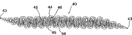
Fig. 6 shows one in order to form the bar 40 of snakelike ladder according to the present invention around dilator.Bar 40 has the snakelike side band 44,45 that connects by cross bar 46.Make bar 40 at its end convergent, so that 44,45 43 everywhere convergents of snakelike side band in the end.
Fig. 7 shows a snakelike ladder according to the present invention around dilator 50, is in the not state of expansion.As shown in Figure 7, the end 43 of convergent can be connected on the corresponding adjacent turn.
As shown in Figure 5, when snakelike ladder when dilator is expanded, outside radial force makes the knee 38 on the snakelike side band 34,35 open on the dilator, thereby the length of grid 37 is increased along the hand of spiral.This feature of the expansible grid of this bar allows the total length of bar to increase along the hand of spiral.By when dilator is expanded, making this bar itself elongated along the hand of spiral, just held the increase of dilator diameters, and needn't this bar of unwinding.By this way, can keep enclosing 31 number, and avoid end 33 to rotate.In fact, because end 33 do not rotate, thus can they be welded on the corresponding adjacent turn 31 as mentioned above, thus a level and smooth end formed.Can weld other the adjacent point on the dilator circle 31 similarly,, and not sacrifice flexibility with the stability of increase dilator.
Snakelike ladder according to the present invention has kept the flexibility relevant with the filament winding dilator around dilator, but has avoided some problems relevant with these dilators.Snakelike ladder is relatively stable and be difficult for displacement or inclination around the circle of dilator, this problem not only with Maass ' straight single band coiling dilator of 545 patent disclosures is relevant, and with for example be with coiling dilator and Cordis Crossflex dilator relevant Wiktor ' 062 and ' 732 patent disclosures snakelike single.In addition, snakelike ladder according to the present invention provides successive supporting around dilator to vascular tissue, and does not have deleterious high percentage ratio metal coverage rate.Can expand along the hand of spiral on length owing to make the bar of dilator, so this bar can be elongated and hold enlarged diameter during expansion, therefore obviously avoided the end rotate and the expansion hour circle with enclose between gap smaller or open problem.
Can for example make around the bar of dilator in order to constitute snakelike ladder by wire metal or flat metal.When using flat metal, for example can form decorative pattern in this by cut or chemical etching.Also can so make dilator: at first make bar, this bar of spiral winding to be to form dilator then, if desired the end of bar is welded on the adjacent circle then.As selection, can so form dilator: on pipe fitting, directly form required decorative pattern by cut or chemical etching, perhaps on a flat sheet, form required decorative pattern, then this flat sheet is wound into a pipe fitting also for example by being welded to connect the edge by cut or chemical etching.Can adopt other any suitable manufacture method manufacturing known in the art according to dilator of the present invention.
Embodiment described here only is that other changes all in the scope of the present invention that claims limited for example.
Claims (14)
1. dilator, become the bar of a series of coiling circles to constitute by spiral winding, wherein this bar has at least two side bands, wherein each at least two side bands all is configured as the Serpentis shape form that comprises a series of knee, wherein at least two of this bar side bands are interconnected, in case and wherein dilator expansion, the knee of at least two side bands just opens so that along hand of spiral lengthening bar, thereby the permission dilator is expanded and do not made this bar that any tangible unwinding is arranged.
2. dilator as claimed in claim 1, wherein at least two snakelike side bands are interconnected by cross bar.
3. dilator as claimed in claim 2, wherein cross bar connects the adjacent knee at least two snakelike side bands.
4. dilator as claimed in claim 3, wherein the adjacent knee that is connected by each cross bar is faced along opposite direction.
5. dilator as claimed in claim 3, wherein cross bar connects at least two snakelike side bands with periodic interval, and wherein each at least two snakelike side bands has at least one knee between cross bar in succession.
6. dilator as claimed in claim 2, wherein said cross bar is straight.
7. dilator as claimed in claim 2, wherein said cross bar has knee.
8. dilator as claimed in claim 2, wherein cross bar extends perpendicular to the hand of spiral of coiling bar usually.
9. dilator as claimed in claim 1, wherein bar has two ends, and wherein at least two side bands are restrained towards the other side at the two ends of bar, make the two ends convergent of bar.
10. dilator as claimed in claim 1, wherein bar has two ends, the first end of bar is positioned at first end of dilator, and the second end of bar is positioned at second end of dilator, and wherein each end of bar all is connected on the adjacent turn of dilator.
11. dilator as claimed in claim 10, wherein each end of bar is all by being welded to connect on this adjacent turn.
12. dilator as claimed in claim 1, wherein bar is made by wire rod.
13. dilator as claimed in claim 1, wherein bar is made by flat metal.
14. dilator as claimed in claim 1, wherein by make this bar then this bar of spiral winding become dilator to make this dilator.
Applications Claiming Priority (2)
| Application Number | Priority Date | Filing Date | Title |
|---|---|---|---|
| US09/204,771 | 1998-12-03 | ||
| US09/204,771 US6355059B1 (en) | 1998-12-03 | 1998-12-03 | Serpentine coiled ladder stent |
Publications (1)
| Publication Number | Publication Date |
|---|---|
| CN1255385A true CN1255385A (en) | 2000-06-07 |
Family
ID=22759374
Family Applications (1)
| Application Number | Title | Priority Date | Filing Date |
|---|---|---|---|
| CN99118499A Pending CN1255385A (en) | 1998-12-03 | 1999-09-03 | S-shaped ladder wound dilator |
Country Status (22)
| Country | Link |
|---|---|
| US (1) | US6355059B1 (en) |
| EP (1) | EP1005842B1 (en) |
| JP (2) | JP4340940B2 (en) |
| KR (1) | KR100318784B1 (en) |
| CN (1) | CN1255385A (en) |
| AR (1) | AR021796A1 (en) |
| AU (2) | AU763391B2 (en) |
| BR (1) | BR9904174A (en) |
| CA (1) | CA2279664C (en) |
| DE (2) | DE69941108D1 (en) |
| EE (1) | EE04037B1 (en) |
| GB (1) | GB2344291B (en) |
| IL (1) | IL131611A (en) |
| MX (1) | MXPA99011171A (en) |
| NO (1) | NO315923B1 (en) |
| NZ (1) | NZ337664A (en) |
| PL (1) | PL336863A1 (en) |
| RU (1) | RU2219872C2 (en) |
| SG (1) | SG81293A1 (en) |
| SK (1) | SK165499A3 (en) |
| UA (1) | UA54516C2 (en) |
| WO (1) | WO2000032138A1 (en) |
Cited By (1)
| Publication number | Priority date | Publication date | Assignee | Title |
|---|---|---|---|---|
| CN101902992B (en) * | 2007-12-19 | 2012-11-28 | 因瓦泰克技术中心有限公司 | Modular stent assembly |
Families Citing this family (70)
| Publication number | Priority date | Publication date | Assignee | Title |
|---|---|---|---|---|
| US7204848B1 (en) | 1995-03-01 | 2007-04-17 | Boston Scientific Scimed, Inc. | Longitudinally flexible expandable stent |
| US20070073384A1 (en) * | 1995-03-01 | 2007-03-29 | Boston Scientific Scimed, Inc. | Longitudinally flexible expandable stent |
| EP1477133B9 (en) | 1996-03-05 | 2007-11-21 | Evysio Medical Devices Ulc | Expandable stent |
| CA2192520A1 (en) | 1996-03-05 | 1997-09-05 | Ian M. Penn | Expandable stent and method for delivery of same |
| US6796997B1 (en) | 1996-03-05 | 2004-09-28 | Evysio Medical Devices Ulc | Expandable stent |
| US20040106985A1 (en) * | 1996-04-26 | 2004-06-03 | Jang G. David | Intravascular stent |
| US6241760B1 (en) * | 1996-04-26 | 2001-06-05 | G. David Jang | Intravascular stent |
| US6235053B1 (en) * | 1998-02-02 | 2001-05-22 | G. David Jang | Tubular stent consists of chevron-shape expansion struts and contralaterally attached diagonal connectors |
| JP4636634B2 (en) | 1996-04-26 | 2011-02-23 | ボストン サイエンティフィック サイムド,インコーポレイテッド | Intravascular stent |
| US5954743A (en) * | 1996-04-26 | 1999-09-21 | Jang; G. David | Intravascular stent |
| US8353948B2 (en) * | 1997-01-24 | 2013-01-15 | Celonova Stent, Inc. | Fracture-resistant helical stent incorporating bistable cells and methods of use |
| JP4351388B2 (en) * | 1998-03-04 | 2009-10-28 | ボストン サイエンティフィック リミテッド | Improved stent cell structure |
| US6193744B1 (en) * | 1998-09-10 | 2001-02-27 | Scimed Life Systems, Inc. | Stent configurations |
| US8382821B2 (en) | 1998-12-03 | 2013-02-26 | Medinol Ltd. | Helical hybrid stent |
| US20040267349A1 (en) | 2003-06-27 | 2004-12-30 | Kobi Richter | Amorphous metal alloy medical devices |
| US6503270B1 (en) * | 1998-12-03 | 2003-01-07 | Medinol Ltd. | Serpentine coiled ladder stent |
| US20060122691A1 (en) * | 1998-12-03 | 2006-06-08 | Jacob Richter | Hybrid stent |
| US20060178727A1 (en) * | 1998-12-03 | 2006-08-10 | Jacob Richter | Hybrid amorphous metal alloy stent |
| US20070219642A1 (en) * | 1998-12-03 | 2007-09-20 | Jacob Richter | Hybrid stent having a fiber or wire backbone |
| AU5795401A (en) * | 2000-08-10 | 2002-02-14 | Cordis Corporation | Low profile radio-opaque stent with increased longitudinal flexibility and radial rigidity |
| US7766956B2 (en) * | 2000-09-22 | 2010-08-03 | Boston Scientific Scimed, Inc. | Intravascular stent and assembly |
| US6602283B2 (en) | 2001-04-06 | 2003-08-05 | Scimed Life Systems, Inc. | Stent design |
| ES2320742T3 (en) | 2001-11-09 | 2009-05-28 | Angioscore, Inc. | BALL CATHETER WITH NON-DISPLAYABLE ENDOPROTESIS. |
| US20040111108A1 (en) | 2001-11-09 | 2004-06-10 | Farnan Robert C. | Balloon catheter with non-deployable stent |
| EP1917931A3 (en) | 2001-12-03 | 2013-02-27 | Intek Technology LLC | Multi-segment modular stent and methods for manufacturing stents |
| US6849084B2 (en) * | 2002-12-31 | 2005-02-01 | Intek Technology L.L.C. | Stent delivery system |
| US20050021070A1 (en) * | 2003-01-21 | 2005-01-27 | Angioscore, Inc. | Methods and apparatus for manipulating vascular prostheses |
| US8080026B2 (en) | 2003-01-21 | 2011-12-20 | Angioscore, Inc. | Apparatus and methods for treating hardened vascular lesions |
| US7686824B2 (en) * | 2003-01-21 | 2010-03-30 | Angioscore, Inc. | Apparatus and methods for treating hardened vascular lesions |
| US7179286B2 (en) * | 2003-02-21 | 2007-02-20 | Boston Scientific Scimed, Inc. | Stent with stepped connectors |
| US7112216B2 (en) * | 2003-05-28 | 2006-09-26 | Boston Scientific Scimed, Inc. | Stent with tapered flexibility |
| US7131993B2 (en) * | 2003-06-25 | 2006-11-07 | Boston Scientific Scimed, Inc. | Varying circumferential spanned connectors in a stent |
| US9039755B2 (en) | 2003-06-27 | 2015-05-26 | Medinol Ltd. | Helical hybrid stent |
| US9155639B2 (en) * | 2009-04-22 | 2015-10-13 | Medinol Ltd. | Helical hybrid stent |
| US7402170B2 (en) * | 2003-12-30 | 2008-07-22 | Scimed Life Systems, Inc. | Crimp and weld wire connection |
| US7479158B2 (en) * | 2004-02-20 | 2009-01-20 | Boston Scientific Scimed, Inc. | Stent with nested flexible connectors for flexibility and crimpability |
| US20050185061A1 (en) * | 2004-02-23 | 2005-08-25 | Andy Baker | Self photographing camera system |
| US7018403B1 (en) | 2004-09-14 | 2006-03-28 | Advanced Cardiovascular Systems, Inc. | Inclined stent pattern for vulnerable plaque |
| US7914570B2 (en) * | 2004-10-07 | 2011-03-29 | Boston Scientific Scimed, Inc. | Non-shortening helical stent |
| ES2764992T3 (en) | 2005-04-04 | 2020-06-05 | Flexible Stenting Solutions Inc | Flexible stent |
| US10076641B2 (en) | 2005-05-11 | 2018-09-18 | The Spectranetics Corporation | Methods and systems for delivering substances into luminal walls |
| US7637939B2 (en) * | 2005-06-30 | 2009-12-29 | Boston Scientific Scimed, Inc. | Hybrid stent |
| US8043366B2 (en) * | 2005-09-08 | 2011-10-25 | Boston Scientific Scimed, Inc. | Overlapping stent |
| US7988720B2 (en) | 2006-09-12 | 2011-08-02 | Boston Scientific Scimed, Inc. | Longitudinally flexible expandable stent |
| US8623070B2 (en) | 2007-03-08 | 2014-01-07 | Thomas O. Bales | Tapered helical stent and method for manufacturing the stent |
| US9265636B2 (en) * | 2007-05-25 | 2016-02-23 | C. R. Bard, Inc. | Twisted stent |
| US20080319534A1 (en) * | 2007-06-22 | 2008-12-25 | Medtronic Vascular, Inc. | Stent With Improved Mechanical Properties |
| US7988723B2 (en) | 2007-08-02 | 2011-08-02 | Flexible Stenting Solutions, Inc. | Flexible stent |
| US9149376B2 (en) | 2008-10-06 | 2015-10-06 | Cordis Corporation | Reconstrainable stent delivery system |
| AU2016213923B9 (en) * | 2009-04-22 | 2017-11-16 | Medinol Ltd. | Helical hybrid stent |
| US9060889B2 (en) | 2009-09-18 | 2015-06-23 | Medtronic Vascular, Inc. | Methods for forming an orthogonal end on a helical stent |
| KR20110088975A (en) * | 2010-01-29 | 2011-08-04 | 주식회사 뉴로벤션 | Stent |
| US20110218615A1 (en) * | 2010-03-02 | 2011-09-08 | Medtronic Vascular, Inc. | Stent With Multi-Crown Constraint and Method for Ending Helical Wound Stents |
| US8206434B2 (en) | 2010-03-02 | 2012-06-26 | Medtronic Vascular, Inc. | Stent with sinusoidal wave form and orthogonal end and method for making same |
| EP2380604A1 (en) | 2010-04-19 | 2011-10-26 | InnoRa Gmbh | Improved coating formulations for scoring or cutting balloon catheters |
| US8801775B2 (en) * | 2010-04-27 | 2014-08-12 | Medtronic Vascular, Inc. | Helical stent with opposing and/or alternating pitch angles |
| US8328072B2 (en) | 2010-07-19 | 2012-12-11 | Medtronic Vascular, Inc. | Method for forming a wave form used to make wound stents |
| US10231855B2 (en) * | 2010-08-02 | 2019-03-19 | CARDINAL HEALTH SWITZERLAND 515 GmbH | Flexible helical stent having intermediate non-helical region |
| US8632559B2 (en) | 2010-09-21 | 2014-01-21 | Angioscore, Inc. | Method and system for treating valve stenosis |
| US9296034B2 (en) | 2011-07-26 | 2016-03-29 | Medtronic Vascular, Inc. | Apparatus and method for forming a wave form for a stent from a wire |
| US9242290B2 (en) | 2012-04-03 | 2016-01-26 | Medtronic Vascular, Inc. | Method and apparatus for creating formed elements used to make wound stents |
| US9238260B2 (en) | 2012-04-18 | 2016-01-19 | Medtronic Vascular, Inc. | Method and apparatus for creating formed elements used to make wound stents |
| US9364351B2 (en) | 2012-04-23 | 2016-06-14 | Medtronic Vascular, Inc. | Method for forming a stent |
| US9364358B2 (en) | 2012-07-27 | 2016-06-14 | Medinol Ltd. | Catheter with retractable cover and pressurized fluid |
| CA2906372C (en) | 2013-03-14 | 2018-08-28 | Medinol Ltd. | Helical hybrid stent |
| US10117668B2 (en) | 2013-10-08 | 2018-11-06 | The Spectranetics Corporation | Balloon catheter with non-deployable stent having improved stability |
| JP2019528824A (en) | 2016-09-15 | 2019-10-17 | メディノール リミテッドMedinol Ltd. | Blood clot collector |
| DE102016118600B4 (en) | 2016-09-30 | 2022-03-31 | Acandis Gmbh | Medical device, ribbon-shaped lattice structure, kit and method for manufacturing the same |
| US20210251783A1 (en) | 2020-02-19 | 2021-08-19 | Medinol Ltd. | Helical stent with enhanced crimping |
| IL310183A (en) | 2021-08-17 | 2024-03-01 | Medinol Ltd | Stent with enhanced low crimping profile |
Family Cites Families (32)
| Publication number | Priority date | Publication date | Assignee | Title |
|---|---|---|---|---|
| CA1204643A (en) | 1981-09-16 | 1986-05-20 | Hans I. Wallsten | Device for application in blood vessels or other difficulty accessible locations and its use |
| US5102417A (en) | 1985-11-07 | 1992-04-07 | Expandable Grafts Partnership | Expandable intraluminal graft, and method and apparatus for implanting an expandable intraluminal graft |
| US4733665C2 (en) | 1985-11-07 | 2002-01-29 | Expandable Grafts Partnership | Expandable intraluminal graft and method and apparatus for implanting an expandable intraluminal graft |
| US4649922A (en) | 1986-01-23 | 1987-03-17 | Wiktor Donimik M | Catheter arrangement having a variable diameter tip and spring prosthesis |
| US4800882A (en) | 1987-03-13 | 1989-01-31 | Cook Incorporated | Endovascular stent and delivery system |
| US4969458A (en) | 1987-07-06 | 1990-11-13 | Medtronic, Inc. | Intracoronary stent and method of simultaneous angioplasty and stent implant |
| US5133732A (en) | 1987-10-19 | 1992-07-28 | Medtronic, Inc. | Intravascular stent |
| US4886062A (en) | 1987-10-19 | 1989-12-12 | Medtronic, Inc. | Intravascular radially expandable stent and method of implant |
| US5019090A (en) | 1988-09-01 | 1991-05-28 | Corvita Corporation | Radially expandable endoprosthesis and the like |
| US4913141A (en) | 1988-10-25 | 1990-04-03 | Cordis Corporation | Apparatus and method for placement of a stent within a subject vessel |
| US4856516A (en) | 1989-01-09 | 1989-08-15 | Cordis Corporation | Endovascular stent apparatus and method |
| CA2026604A1 (en) | 1989-10-02 | 1991-04-03 | Rodney G. Wolff | Articulated stent |
| US5108417A (en) * | 1990-09-14 | 1992-04-28 | Interface Biomedical Laboratories Corp. | Anti-turbulent, anti-thrombogenic intravascular stent |
| DE9117152U1 (en) | 1990-10-09 | 1996-07-11 | Cook Inc | Stent |
| US5161547A (en) | 1990-11-28 | 1992-11-10 | Numed, Inc. | Method of forming an intravascular radially expandable stent |
| US5135536A (en) | 1991-02-05 | 1992-08-04 | Cordis Corporation | Endovascular stent and method |
| US5116365A (en) | 1991-02-22 | 1992-05-26 | Cordis Corporation | Stent apparatus and method for making |
| US5314472A (en) * | 1991-10-01 | 1994-05-24 | Cook Incorporated | Vascular stent |
| FR2683449A1 (en) | 1991-11-08 | 1993-05-14 | Cardon Alain | ENDOPROTHESIS FOR TRANSLUMINAL IMPLANTATION. |
| US5449373A (en) | 1994-03-17 | 1995-09-12 | Medinol Ltd. | Articulated stent |
| US5733303A (en) | 1994-03-17 | 1998-03-31 | Medinol Ltd. | Flexible expandable stent |
| EP0813397A4 (en) * | 1995-03-10 | 1999-10-06 | Cardiovascular Concepts Inc | Tubular endoluminar prosthesis having oblique ends |
| US5613981A (en) * | 1995-04-21 | 1997-03-25 | Medtronic, Inc. | Bidirectional dual sinusoidal helix stent |
| US5707387A (en) * | 1996-03-25 | 1998-01-13 | Wijay; Bandula | Flexible stent |
| US5925061A (en) | 1997-01-13 | 1999-07-20 | Gore Enterprise Holdings, Inc. | Low profile vascular stent |
| FR2760351B1 (en) | 1997-03-04 | 1999-05-28 | Bernard Glatt | HELICAL STENT FORMING DEVICE AND MANUFACTURING METHOD THEREOF |
| US5810872A (en) | 1997-03-14 | 1998-09-22 | Kanesaka; Nozomu | Flexible stent |
| US5824052A (en) * | 1997-03-18 | 1998-10-20 | Endotex Interventional Systems, Inc. | Coiled sheet stent having helical articulation and methods of use |
| US5824053A (en) * | 1997-03-18 | 1998-10-20 | Endotex Interventional Systems, Inc. | Helical mesh endoprosthesis and methods of use |
| US5843168A (en) * | 1997-03-31 | 1998-12-01 | Medtronic, Inc. | Double wave stent with strut |
| DE19717475C1 (en) * | 1997-04-25 | 1998-09-03 | Heraeus Gmbh W C | Radially expandable support structure or stent for tubular vessel in body |
| US5961548A (en) * | 1997-11-18 | 1999-10-05 | Shmulewitz; Ascher | Bifurcated two-part graft and methods of implantation |
-
1998
- 1998-12-03 US US09/204,771 patent/US6355059B1/en not_active Expired - Lifetime
-
1999
- 1999-08-03 SG SG9903731A patent/SG81293A1/en unknown
- 1999-08-04 AU AU42468/99A patent/AU763391B2/en not_active Expired
- 1999-08-05 CA CA002279664A patent/CA2279664C/en not_active Expired - Lifetime
- 1999-08-26 AU AU54417/99A patent/AU5441799A/en not_active Abandoned
- 1999-08-26 IL IL13161199A patent/IL131611A/en not_active IP Right Cessation
- 1999-08-26 WO PCT/IL1999/000469 patent/WO2000032138A1/en active Application Filing
- 1999-09-03 CN CN99118499A patent/CN1255385A/en active Pending
- 1999-09-06 NZ NZ337664A patent/NZ337664A/en unknown
- 1999-09-07 EP EP99117409A patent/EP1005842B1/en not_active Expired - Lifetime
- 1999-09-07 DE DE69941108T patent/DE69941108D1/en not_active Expired - Lifetime
- 1999-09-07 AR ARP990104492A patent/AR021796A1/en not_active Application Discontinuation
- 1999-09-07 DE DE19942704A patent/DE19942704A1/en not_active Withdrawn
- 1999-09-08 GB GB9921090A patent/GB2344291B/en not_active Expired - Lifetime
- 1999-09-15 BR BR9904174-0A patent/BR9904174A/en not_active IP Right Cessation
- 1999-10-04 KR KR1019990042539A patent/KR100318784B1/en not_active IP Right Cessation
- 1999-10-12 RU RU99121520/14A patent/RU2219872C2/en not_active IP Right Cessation
- 1999-11-30 PL PL99336863A patent/PL336863A1/en unknown
- 1999-12-01 UA UA99126541A patent/UA54516C2/en unknown
- 1999-12-01 EE EEP199900449A patent/EE04037B1/en not_active IP Right Cessation
- 1999-12-02 JP JP34383899A patent/JP4340940B2/en not_active Expired - Lifetime
- 1999-12-02 MX MXPA99011171A patent/MXPA99011171A/en not_active Application Discontinuation
- 1999-12-02 SK SK1654-99A patent/SK165499A3/en unknown
- 1999-12-02 NO NO19995915A patent/NO315923B1/en not_active IP Right Cessation
-
2007
- 2007-02-20 JP JP2007038866A patent/JP4735989B2/en not_active Expired - Lifetime
Cited By (1)
| Publication number | Priority date | Publication date | Assignee | Title |
|---|---|---|---|---|
| CN101902992B (en) * | 2007-12-19 | 2012-11-28 | 因瓦泰克技术中心有限公司 | Modular stent assembly |
Also Published As
Similar Documents
| Publication | Publication Date | Title |
|---|---|---|
| CN1255385A (en) | S-shaped ladder wound dilator | |
| AU769111B2 (en) | Serpentine coiled ladder stent | |
| US5833699A (en) | Extending ribbon stent | |
| US5217483A (en) | Intravascular radially expandable stent | |
| US7637938B2 (en) | Flexible stent | |
| US20080269873A1 (en) | Flexible expandable stent | |
| US20050149168A1 (en) | Stent to be deployed on a bend | |
| EP1235535B1 (en) | Stent | |
| CZ9904283A3 (en) | Stent for implanting in a blood vessel |
Legal Events
| Date | Code | Title | Description |
|---|---|---|---|
| C06 | Publication | ||
| PB01 | Publication | ||
| C10 | Entry into substantive examination | ||
| SE01 | Entry into force of request for substantive examination | ||
| C02 | Deemed withdrawal of patent application after publication (patent law 2001) | ||
| WD01 | Invention patent application deemed withdrawn after publication |