CN1254209C - Drawer slideway and method for realizing assembling it thereof - Google Patents
Drawer slideway and method for realizing assembling it thereof Download PDFInfo
- Publication number
- CN1254209C CN1254209C CNB021249377A CN02124937A CN1254209C CN 1254209 C CN1254209 C CN 1254209C CN B021249377 A CNB021249377 A CN B021249377A CN 02124937 A CN02124937 A CN 02124937A CN 1254209 C CN1254209 C CN 1254209C
- Authority
- CN
- China
- Prior art keywords
- guide rail
- wall
- cramp
- main body
- notch
- Prior art date
- Legal status (The legal status is an assumption and is not a legal conclusion. Google has not performed a legal analysis and makes no representation as to the accuracy of the status listed.)
- Expired - Fee Related
Links
Images


Classifications
-
- A—HUMAN NECESSITIES
- A47—FURNITURE; DOMESTIC ARTICLES OR APPLIANCES; COFFEE MILLS; SPICE MILLS; SUCTION CLEANERS IN GENERAL
- A47B—TABLES; DESKS; OFFICE FURNITURE; CABINETS; DRAWERS; GENERAL DETAILS OF FURNITURE
- A47B88/00—Drawers for tables, cabinets or like furniture; Guides for drawers
- A47B88/40—Sliding drawers; Slides or guides therefor
- A47B88/423—Fastening devices for slides or guides
- A47B88/427—Fastening devices for slides or guides at drawer side
Abstract
The quick assembly draw guide comprises a shaped body which has a device for connection to the wall of the draw. This comprises a first member for the attachment to the wall and means for deforming a portion of the surface for the displacement of the first attachment member along a direction perpendicular to the axis of the body up to a position substantially coinciding with the thickness of the wall. The procedure for the realisation and assembly of the guide consists of shearing a slot and at the same time two opposite tabs leaving a staple between the tabs and said slot, of shearing a point facing the staple on the vertical side of the guide, of deforming the slot to displace said tabs simultaneously along a direction perpendicular to the axis of the guide up to a position substantially coinciding with the thickness of the wall, of associating the wall with the guide, of bending the tabs by 90 degrees and of applying a pressure on the tabs and the point against the wall to anchor them to it.
Description
Technical field
The method that the present invention relates to a kind of drawer guideway and realize and assemble described drawer guideway.
Background technology
As everyone knows, drawer guideway comprises a main body, and main body has downside, and main body is connected to the bottom of the sidewall of described drawer, and this main body has the horizontal expansion greater than the thickness of the sidewall of above-mentioned drawer.
Described guide rail also comprises the hook of the sidewall that is connected to described drawer.
This conventional drawer guide rail has some shortcomings, mainly due to the following fact, because the downside of described guide rail has the horizontal expansion greater than the thickness of described drawer side wall, so consume lot of materials and have a large amount of borings.
Summary of the invention
Therefore, the technical assignment that the present invention proposes is to realize drawer guideway and realize and the method for this drawer guideway of assembling that it has eliminated the defective of above-mentioned prior art.
In this technical assignment, an object of the present invention is to realize the realization of drawer guideway and this drawer guideway and the method for assembling that compare with material requested in the prior art, it reduces the consumption of material in large quantities.
Another object of the present invention is to realize guide rail and method, this guide rail and method can realize very firm and strong hook cramp, it guarantees that described guide rail is connected on the described drawer well, this be since the firm and strong part of described cramp determine by the width of cramp own rather than determine by material thickness.
The present invention at last but be not that least important purpose is to realize guide rail and a kind of method, it makes cramp very firm and strong, owing to they are not subjected to various deformation, various deformation may cause weakening the intensity of described cramp.
Technical assignment of the present invention and these and other objects, obtain by the following technical solutions: realize the drawer guideway of assembling fast, this drawer guideway comprises a main body that is shaped, this main body is on the stayed surface of the wall of the side of drawer, have described main body is connected to interface unit on the described wall, it is characterized in that: described interface unit comprises at least one first connecting elements and parts, described first connecting elements is used to be connected to described wall, the part distortion that described parts are used to make described surface with described first connecting elements along arriving basically and the wall thickness consistent location until arriving one perpendicular to the direction displacement of the axis of described main body.
Valuably, the invention still further relates to the method that realizes and assemble drawer guideway, it is characterized in that: described method is made of following, on guide rail surface, shear notch, its be suitable for supporting described drawer side wall and shear two relative cramps simultaneously, between described cramp and described notch, stay stator; At tip of vertical lateral shear of described guide rail, this tip is towards described stator; Make the distortion of described notch with simultaneously along perpendicular to the described cramp of direction dislocation of the axis of guide rail until arrive one basically with the described wall thickness positions aligning of coincideing; Described wall and described track combination; Exert pressure so that they are fixed on the wall on described cramp and described tip 90 ° of described cramp bendings and facing to described wall.
And, in the claim of back, limit further feature of the present invention.
Description of drawings
From drawer guideway of the present invention and realize with the method for this drawer guideway of assembling preferably but be not the explanation of unique embodiment, the more feature and advantage of the present invention will become clearer, this guide rail is illustrated the purpose for use in expression rather than qualification in the accompanying drawings, wherein:
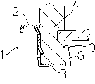
Before Fig. 1 is illustrated in the cramp bending, the plane of the drawer guideway that makes up with drawer (representing) according to the present invention with chain-dotted line;
Fig. 2 represents the plane of the part of the guide rail that also is not deformed according to the present invention;
The plane of the part of the guide rail of the Fig. 2 after Fig. 3 represents to be deformed;
Fig. 4 represents and the plane of the part of the guide rail of Fig. 3 of the drawer combination of representing with chain-dotted line that cramp (tab) and connector are folded;
Fig. 5 represents the profile cut open along the V-V line of Fig. 4; And
Fig. 6 represents not to be added to the described guide rail front view on the drawer.
The specific embodiment
With reference to the figure that quotes, the whole drawer guideway of Reference numeral 1 expression.
Valuably, the Breadth Maximum on the surface 3 of main body 2 is less than the minimum thickness of the wall 4 of described drawer.
And guide rail 1 comprises second connecting elements 8, its on the side relative with first connecting elements 6 with wall 4 engagements.As shown in FIG., first connecting elements 6 comprises a cramp, this cramp with the surperficial identical plane of main body 2 on extend and be equipped with hook head 9 in its end.
Especially, guide rail of the present invention comprises at least two cramps 6, and these two cramps are identical and face mutually and arrange.Valuably, cramp 6 has the desired shape or cross-section line perpendicular to main body.
And deformation component 7 comprises at least one notch, and the axis that this notch is parallel to main body extends and constitute the stator 11 that supports described two cramps 6 on the part on the surface 3 of main body.
In a preferred embodiment, second connecting elements 8 is in a zone and wall 4 engagements, and this zone equates with two cramps, 6 distances.
The present invention also relates to realize and assemble the method for drawer guideway.
Described method is made of following, shears notch 7 and two relative cramps 6 simultaneously on the surface 3 of guide rail 1, stays stator 11 between described cramp and notch 7, and notch is suitable for supporting the wall 4 of the side of described drawer.
Described method also is included on the vertical side of guide rail 1 and shears a tip 8, most advanced and sophisticated 8 towards stator 11, thereby and make notch 7 distortion make two cramps 6 simultaneously along perpendicular to the direction displacement of guide rail 1 axis until arriving a position, this position conforms to wall 4 thickness basically.
Described method also comprises wall 4 and guide rail 1 is linked, and exerts pressure so that they are fixed to the upper on cramp 6 and most advanced and sophisticated 8 cramp 6 90 ° of bendings and facing to wall 4.
Valuably, described cramp 6 has perpendicular to guide rail 1 desired shape or cross-section line.
And notch 7 has widened section 12 in its end makes the distortion of notch 7 and stator 11 become easy with the displacement that cramp 6 exceeds surperficial 3 Breadth Maximums.
In practice, have been noted that drawer guideway of the present invention and realize that the method with the described drawer guideway of assembling is useful especially, because they can economical with materials and minimizing borings with respect to prior art.
Thus, guide rail of the present invention in practice is to save very much cost.
Gou Si described drawer guideway and the method with the described drawer guideway of assembling of realizing drop on the present invention easily and conceive various modifications and variations in the scope like this; And all details can be replaced with technical equivalent elements.
In practice, needs and state according to technology can use any material and size.Here all essence descriptions, illustrated and claimed all is to be used for illustration purpose.
Claims (12)
1. the quick drawer guideway that assembles, comprise a main body that is shaped, it is on the stayed surface of the wall of the side of drawer, have described main body is connected to interface unit on the described wall, it is characterized in that: described interface unit comprises at least one first connecting elements and parts, described first connecting elements is used to be connected to described wall, the part distortion that described parts are used to make described surface with described first connecting elements along perpendicular to the direction displacement of the axis of main body until arrive one basically with the identical position that conforms to of wall thickness.
2. guide rail according to claim 1 is characterized in that: the Breadth Maximum on the described surface of described main body is less than the minimum thickness of the described wall of described drawer.
3. guide rail according to claim 1 and 2 is characterized in that: described guide rail comprises at least one second connecting elements, itself and described wall engagement on the relative side of described first connecting elements.
4. guide rail according to claim 1 and 2 is characterized in that: described first connecting elements comprises a cramp, and described cramp extends on the plane identical with the described surface of described main body and is equipped with hook head in its end.
5. guide rail according to claim 3 is characterized in that: described interface unit comprises at least two identical cramps, and they are mutually in the face of arranging.
6. guide rail according to claim 1 and 2 is characterized in that: described cramp has the desired shape or cross-section line perpendicular to described main body.
7. guide rail according to claim 1 and 2, it is characterized in that: described deformation component comprises at least one notch, the axis that described notch is parallel to described main body extends and limit a stator on the part on the described surface of described main body, and described stator supports described two cramps.
8. guide rail according to claim 1 and 2 is characterized in that: described notch has widened section in its end, so that the distortion of the described part on described surface and described stator and the displacement of described cramp outside described maximum width of face are easy.
9. guide rail according to claim 5 is characterized in that: described second connecting elements is in a zone and described wall engagement, and this zone equates to described two cramps distance.
10. realize and assemble the method for drawer guideway, it is characterized in that: described method comprises following: shear notch and while two relative cramps on the surface of guide rail, guide rail is suitable for supporting the wall of the side of described drawer, stays next stator between described cramp and described notch; Vertical side at described guide rail is sheared a tip, and this tip is towards described stator; Make the distortion of described notch with simultaneously along perpendicular to described two cramps of direction dislocation of the axis of described guide rail until arrive one basically with the described wall thickness consistent location of coincideing; Make up described wall and described guide rail; Exert pressure so that they are fixed on the wall on described cramp and described tip 90 ° of described cramp bendings and facing to described wall.
11. method according to claim 10 is characterized in that: described cramp has the desired shape or cross-section line perpendicular to described guide rail.
12. according to claim 10 or 11 described methods, it is characterized in that: described notch has widened section at its both ends, makes the distortion of described notch and described stator and described cramp easy in the extraneous displacement of described maximum width of face.
Applications Claiming Priority (2)
| Application Number | Priority Date | Filing Date | Title |
|---|---|---|---|
| IT2001MI001821A ITMI20011821A1 (en) | 2001-08-29 | 2001-08-29 | GUIDE FOR DRAWERS AND PROCEDURE FOR ITS REALIZATION AND ASSEMBLY |
| IT001821A/2001 | 2001-08-29 |
Publications (2)
| Publication Number | Publication Date |
|---|---|
| CN1406539A CN1406539A (en) | 2003-04-02 |
| CN1254209C true CN1254209C (en) | 2006-05-03 |
Family
ID=11448307
Family Applications (1)
| Application Number | Title | Priority Date | Filing Date |
|---|---|---|---|
| CNB021249377A Expired - Fee Related CN1254209C (en) | 2001-08-29 | 2002-06-26 | Drawer slideway and method for realizing assembling it thereof |
Country Status (14)
| Country | Link |
|---|---|
| US (1) | US6883886B2 (en) |
| EP (1) | EP1287764B1 (en) |
| JP (1) | JP3808815B2 (en) |
| KR (1) | KR100602740B1 (en) |
| CN (1) | CN1254209C (en) |
| AT (1) | ATE291361T1 (en) |
| BR (1) | BR0202996A (en) |
| CZ (1) | CZ20021281A3 (en) |
| DE (1) | DE60203353T2 (en) |
| ES (1) | ES2239182T3 (en) |
| HK (1) | HK1053414A1 (en) |
| HU (1) | HUP0201200A2 (en) |
| IT (1) | ITMI20011821A1 (en) |
| PL (1) | PL355747A1 (en) |
Families Citing this family (6)
| Publication number | Priority date | Publication date | Assignee | Title |
|---|---|---|---|---|
| ITMI20011821A1 (en) * | 2001-08-29 | 2003-03-01 | Salice Arturo Spa | GUIDE FOR DRAWERS AND PROCEDURE FOR ITS REALIZATION AND ASSEMBLY |
| DE20209416U1 (en) * | 2002-06-17 | 2003-10-30 | Alfit Ag Goetzis | Arrangement for connecting a drawer frame to the bottom of a drawer |
| JP4102227B2 (en) * | 2003-03-20 | 2008-06-18 | アイリスオーヤマ株式会社 | Rail fixing part structure |
| GB2439914A (en) * | 2006-07-12 | 2008-01-16 | Window Fab & Fixing Supplies | Drawer slide runner component |
| CN101375758B (en) * | 2007-08-28 | 2010-06-23 | 三千金属工业股份有限公司 | Method for producing synchronous sliding track |
| CN108032080B (en) * | 2017-12-18 | 2020-02-07 | 无锡众望四维科技有限公司 | Automatic drawer assembly line |
Family Cites Families (15)
| Publication number | Priority date | Publication date | Assignee | Title |
|---|---|---|---|---|
| US556183A (en) * | 1896-03-10 | Half to joseph mandel | ||
| AT344362B (en) * | 1975-08-04 | 1978-07-25 | Grass Alfred Metallwaren | DRAWER GUIDE RAIL |
| DE8431503U1 (en) * | 1984-10-26 | 1985-01-31 | Paul Hettich GmbH & Co, 4983 Kirchlengern | DRAWER |
| GB2196835B (en) * | 1986-11-05 | 1990-04-04 | Elmbridge Production Engineers | Furniture fittings |
| AT395810B (en) * | 1987-03-05 | 1993-03-25 | Blum Gmbh Julius | DRAWER |
| AT389434B (en) * | 1987-12-24 | 1989-12-11 | Blum Gmbh Julius | DRAWER |
| AT393069B (en) * | 1989-11-20 | 1991-08-12 | Alfit Ag | DRAWER |
| DE4011815A1 (en) * | 1990-04-12 | 1991-10-17 | Lautenschlaeger Kg Karl | METAL FRAME FOR DRAWER WALLS |
| AT400213B (en) * | 1990-11-30 | 1995-11-27 | Alfit Ag | DRAWER |
| DE9303903U1 (en) * | 1993-03-17 | 1994-04-14 | Grass Ag | Drawer with frame and drawer bottom |
| AT401856B (en) * | 1993-05-13 | 1996-12-27 | Blum Gmbh Julius | DRAWER |
| DE19541767B4 (en) * | 1995-11-09 | 2004-09-23 | Grass Gmbh | Drawer rail and process for its manufacture |
| AT409069B (en) * | 1997-07-03 | 2002-05-27 | Blum Gmbh Julius | drawer |
| US6378967B1 (en) * | 2000-08-29 | 2002-04-30 | Grass America, Inc. | Clamp-on drawer slide |
| ITMI20011821A1 (en) * | 2001-08-29 | 2003-03-01 | Salice Arturo Spa | GUIDE FOR DRAWERS AND PROCEDURE FOR ITS REALIZATION AND ASSEMBLY |
-
2001
- 2001-08-29 IT IT2001MI001821A patent/ITMI20011821A1/en unknown
-
2002
- 2002-04-08 ES ES02007829T patent/ES2239182T3/en not_active Expired - Lifetime
- 2002-04-08 AT AT02007829T patent/ATE291361T1/en active
- 2002-04-08 EP EP02007829A patent/EP1287764B1/en not_active Expired - Lifetime
- 2002-04-08 DE DE60203353T patent/DE60203353T2/en not_active Expired - Lifetime
- 2002-04-11 HU HU0201200A patent/HUP0201200A2/en unknown
- 2002-04-11 CZ CZ20021281A patent/CZ20021281A3/en unknown
- 2002-05-29 US US10/157,767 patent/US6883886B2/en not_active Expired - Fee Related
- 2002-06-26 CN CNB021249377A patent/CN1254209C/en not_active Expired - Fee Related
- 2002-07-15 BR BR0202996-0A patent/BR0202996A/en not_active IP Right Cessation
- 2002-07-16 KR KR1020020041418A patent/KR100602740B1/en not_active IP Right Cessation
- 2002-08-27 JP JP2002246071A patent/JP3808815B2/en not_active Expired - Fee Related
- 2002-08-28 PL PL02355747A patent/PL355747A1/en not_active IP Right Cessation
-
2003
- 2003-08-08 HK HK03105691A patent/HK1053414A1/en not_active IP Right Cessation
Also Published As
| Publication number | Publication date |
|---|---|
| HU0201200D0 (en) | 2002-06-29 |
| HUP0201200A2 (en) | 2007-09-28 |
| CZ20021281A3 (en) | 2003-04-16 |
| DE60203353T2 (en) | 2006-02-09 |
| US20030052579A1 (en) | 2003-03-20 |
| EP1287764A1 (en) | 2003-03-05 |
| ES2239182T3 (en) | 2005-09-16 |
| US6883886B2 (en) | 2005-04-26 |
| ATE291361T1 (en) | 2005-04-15 |
| BR0202996A (en) | 2003-05-27 |
| KR20030019850A (en) | 2003-03-07 |
| PL355747A1 (en) | 2003-03-10 |
| JP2003093179A (en) | 2003-04-02 |
| KR100602740B1 (en) | 2006-07-20 |
| ITMI20011821A0 (en) | 2001-08-29 |
| HK1053414A1 (en) | 2003-10-24 |
| CN1406539A (en) | 2003-04-02 |
| EP1287764B1 (en) | 2005-03-23 |
| DE60203353D1 (en) | 2005-04-28 |
| JP3808815B2 (en) | 2006-08-16 |
| ITMI20011821A1 (en) | 2003-03-01 |
Similar Documents
| Publication | Publication Date | Title |
|---|---|---|
| CN1232716C (en) | Mounting piece for door | |
| CN1208537C (en) | Suspension device | |
| CN1254209C (en) | Drawer slideway and method for realizing assembling it thereof | |
| US7645088B2 (en) | Articulated arm for an awning and method for the production thereof | |
| CN1826474A (en) | Fastener having improved penetration capability | |
| CN1924250A (en) | Decorative plate connection structure | |
| CN214995516U (en) | Wallboard fast-assembling structure | |
| CN1572973A (en) | System for fixing rails on a structure like elevated railway | |
| CN109371766B (en) | Connecting method for curved concrete track beam | |
| CN2676179Y (en) | Painted steel fixture for automobile weather seal insertion and withdraw force testing device | |
| CN2501603Y (en) | Assembling mechanism for guide and guards for bar material continuous rolling guiding device | |
| CN219411627U (en) | Mounting structure of decorative wallboard | |
| CN1097366A (en) | Produce the method and apparatus of heat exchange elements and attached band finned tube thereof | |
| CN201148807Y (en) | Buckled press type glass pressing bar door and window and pressing bar used thereby | |
| CN212823602U (en) | Clamp structure for preventing welding spot from deforming | |
| US6886232B2 (en) | Wiper arms, and method for producing wiper arms | |
| CN209066684U (en) | A kind of GRC curtain wall connecting system | |
| CN217700815U (en) | Trim equipment of bending | |
| CN1210470C (en) | Extendible fastening assembly | |
| CN219787100U (en) | Anti-deformation tool for welding end wall of railway vehicle | |
| CN1007074B (en) | Support of resilient rail clip for wooden sleepers | |
| CN107651544B (en) | Hoistway door pocket fixing assembly and door pocket fixing claw | |
| CN214116107U (en) | RGV track butt joint tool | |
| CN210947536U (en) | Keel assembly and wall surface assembly | |
| CN1129541C (en) | Adjustable two-piece clamp for installing article on wall |
Legal Events
| Date | Code | Title | Description |
|---|---|---|---|
| C06 | Publication | ||
| PB01 | Publication | ||
| C10 | Entry into substantive examination | ||
| SE01 | Entry into force of request for substantive examination | ||
| C14 | Grant of patent or utility model | ||
| GR01 | Patent grant | ||
| C17 | Cessation of patent right | ||
| CF01 | Termination of patent right due to non-payment of annual fee |
Granted publication date: 20060503 Termination date: 20100626 |