CN1247940C - Ice storage air conditioning system cmbined with internally and externally melting ice - Google Patents
Ice storage air conditioning system cmbined with internally and externally melting ice Download PDFInfo
- Publication number
- CN1247940C CN1247940C CNB2004100170916A CN200410017091A CN1247940C CN 1247940 C CN1247940 C CN 1247940C CN B2004100170916 A CNB2004100170916 A CN B2004100170916A CN 200410017091 A CN200410017091 A CN 200410017091A CN 1247940 C CN1247940 C CN 1247940C
- Authority
- CN
- China
- Prior art keywords
- ice
- storage tank
- control valve
- electric control
- water
- Prior art date
- Legal status (The legal status is an assumption and is not a legal conclusion. Google has not performed a legal analysis and makes no representation as to the accuracy of the status listed.)
- Expired - Fee Related
Links
Images


Classifications
-
- Y—GENERAL TAGGING OF NEW TECHNOLOGICAL DEVELOPMENTS; GENERAL TAGGING OF CROSS-SECTIONAL TECHNOLOGIES SPANNING OVER SEVERAL SECTIONS OF THE IPC; TECHNICAL SUBJECTS COVERED BY FORMER USPC CROSS-REFERENCE ART COLLECTIONS [XRACs] AND DIGESTS
- Y02—TECHNOLOGIES OR APPLICATIONS FOR MITIGATION OR ADAPTATION AGAINST CLIMATE CHANGE
- Y02E—REDUCTION OF GREENHOUSE GAS [GHG] EMISSIONS, RELATED TO ENERGY GENERATION, TRANSMISSION OR DISTRIBUTION
- Y02E60/00—Enabling technologies; Technologies with a potential or indirect contribution to GHG emissions mitigation
- Y02E60/14—Thermal energy storage
Abstract
The present invention discloses an ice storing air conditioner system with the combination of internal melting ice and external melting ice. The present invention is composed of a secondary refrigerant loop and a water loop of an air conditioner or an ice water loop, wherein the secondary refrigerant loop is composed of a refrigerating machine, an ice storing tank, a heat exchanger, a secondary refrigerant pump, a constant pressure device of secondary refrigerant, an electric control valve and an electric switch valve; the water loop of the air conditioner is composed of a freezing water pump, a water constant pressure device of the air conditioner, a water collector, a water separator, an ice storing tank, a heat exchanger and an electric control valve; the ice water loop is composed of an additional ice water pump, a heat exchanger and an electric control valve. A refrigerating machine of a secondary refrigerant loop is connected with the ice storing tank in series; the refrigerating machine is positioned at the upstream of the ice storing tank; the modes that refrigeration can be respectively supplied to the refrigerating machine, an internal melting ice and an external melting ice, or two of the refrigerating machine, the internal melting ice and the external melting ice or all of the refrigerating machine, the internal melting ice and the external melting ice together can be realized. The internal melting ice is combined with the external melting ice so the speed rate of the melting ice of the ice storing tank can be greatly improved; therefore, the requirement of low-temperature air supply can be well met, and a refrigerating machine of an air conditioner system can operate by avoiding the peak period. Consequently, the present invention has the advantages that the quality of air conditioners is improved, the initial cost of air conditioner systems is saved, and the operating cost of the ice storing air conditioner system of saved.
Description
Technical field
The present invention relates to the energy accumulation air conditioner technical field, particularly relate to the ice-storage air-conditioning system that a kind of inside and outside ice-melt combines.
Background technology
Ice-storage air-conditioning is to utilize the cheap electric power of electrical network low-load period to freeze by refrigeration machine, the form of cold with latent heat is stored in the ice, in the peak times of power consumption of electricity price costliness, ice-out is discharged the requirement that cold satisfies the air-conditioning refrigeration duty, ice-storage air-conditioning on the one hand can balancing power network load, can therefore have good social benefit and economic benefit for the user saves the operation of air conditioner expense on the other hand.
Along with developing rapidly of ice-storage air-conditioning, because ice-melt can improve lower leaving water temperature, big temperature difference cold air distribution air-conditioning technical has also obtained utilization widely in recent years, big temperature difference cold air distribution The Application of Technology, can reduce the size of water pipe, airduct, reduce the power of water pump, blower fan, can reduce the initial cost and the operating cost of air-conditioning system, simultaneously can also improve the air-conditioning quality, have bright development prospect.
Existing coil system substantially all adopts interior ice-melting mode, be that refrigerating medium flows in coil pipe, heat is passed to ice (water) in the Ice Storage Tank by the coil pipe wall, because (ice) in the Ice Storage Tank water base keeps inactive state, heat transfer efficiency is relatively poor, cause ice-melt speed less, the refrigerating medium that provides temperature very low is provided; Secondly, system also needs a heat exchanger cold of refrigerating medium could be passed to air conditioning water, make the temperature of chilled water be difficult to be lower than 5 ℃, and the cold air distribution system often requires chilled water temperature below 5 ℃, even below 3 ℃.
Because interior ice-melt ice-melt speed is low and also need a heat exchanger that cold is passed to chilled water by refrigerating medium, therefore during the high peak electricity consumption of electricity price, even also have a large amount of ice in the Ice Storage Tank, depend merely on ice-melt and can not satisfy the requirement of refrigeration duty, therefore have to open refrigeration machine associating cooling, the advantage that can not give full play to ice-storage air-conditioning electrical network peak load shifting and save operating cost.
Existing a small amount of system also adopts outer ice-melt, comprise the outer ice melting system that uses the enclosed Ice Storage Tank, have the outer ice melting system of open type Ice Storage Tank and the outer ice melting system of open type Ice Storage Tank of outer ice-melt finned coil with inside, although the three can provide the leaving water temperature lower than interior ice-melt, but when load is big, the not enough phenomenon of ice-melt speed can appear still.
Summary of the invention
Problem at existing coil system existence, the ice-storage air-conditioning system that the object of the present invention is to provide a kind of inside and outside ice-melt to combine, can improve the ice-melt speed of Ice Storage Tank greatly, the requirement and the air-conditioning system refrigeration machine that can better meet cold air distribution are kept away peak load operation.Thereby improve the air-conditioning quality, save the air-conditioning system initial cost, save the ice-storage air-conditioning system operating cost.
In order to reach the purpose of foregoing invention, technical scheme of the present invention realizes as follows:
Scheme 1
The ice-storage air-conditioning system that a kind of inside and outside ice-melt combines comprises air conditioner water constant pressure arrangement, water collector, chilled water pump, first heat exchanger, water knockout drum, refrigerating medium constant pressure arrangement, coolant pump, refrigeration machine, Ice Storage Tank.
1) refrigerating medium loop: the port of export of refrigeration machine divides two-way, lead up to the Ice Storage Tank and first electric control valve, lead up to the second electric control valve bypass, be divided into two-way after converging again, first electric switching valve of leading up to enters first heat exchanger, lead up to second electric switching valve, carry cryogen constant pressure arrangement and coolant pump after converging respectively, coolant pump connects the arrival end of refrigeration machine;
2) air conditioner water loop: water collector connects air conditioner water constant pressure arrangement, air-conditioning backwater, chilled water pump respectively, the chilled water pump outlet is by being divided into two-way behind first heat exchanger, one the tunnel enters Ice Storage Tank through the 3rd electric control valve, and another road is converged with the Ice Storage Tank outlet after by the 4th electric control valve and connect water knockout drum.
Said Ice Storage Tank is enclosed Ice Storage Tank or band ice-melt finned coil open type Ice Storage Tank.
Scheme 2
The ice-storage air-conditioning system that a kind of inside and outside ice-melt combines comprises air conditioner water constant pressure arrangement, water collector, chilled water pump, first heat exchanger, water knockout drum, refrigerating medium constant pressure arrangement, coolant pump, refrigeration machine, Ice Storage Tank, CHP, second heat exchanger.
1) refrigerating medium loop: the port of export of refrigeration machine divides two-way, lead up to the Ice Storage Tank and first electric control valve, lead up to the second electric control valve bypass, be divided into two-way after converging again, first electric switching valve of leading up to enters first heat exchanger, lead up to second electric switching valve, carry cryogen constant pressure arrangement and coolant pump after converging respectively, coolant pump connects the arrival end of refrigeration machine;
2) air conditioner water loop: water collector connects air conditioner water constant pressure arrangement, air-conditioning backwater, chilled water pump respectively, and the chilled water pump outlet connects water knockout drum by first heat exchanger, second heat exchanger successively;
3) frozen water loop: CHP connects second heat exchanger and is divided into two-way then, and the 5th electric control valve of leading up to connects Ice Storage Tank, and another road connects CHP after outlet converges through the 6th electric control valve and Ice Storage Tank.
Scheme 3
The ice-storage air-conditioning system that a kind of inside and outside ice-melt combines comprises air conditioner water constant pressure arrangement, water collector, chilled water pump, first heat exchanger, water knockout drum, refrigerating medium constant pressure arrangement, coolant pump, refrigeration machine, Ice Storage Tank.
1) refrigerating medium loop: the port of export of refrigeration machine divides two-way, lead up to the Ice Storage Tank and first electric control valve, lead up to the second electric control valve bypass, be divided into two-way after converging again, first electric switching valve of leading up to enters first heat exchanger, lead up to second electric switching valve, carry cryogen constant pressure arrangement and coolant pump after converging respectively, coolant pump connects the arrival end of refrigeration machine;
2) air conditioner water loop: water collector connects air conditioner water constant pressure arrangement, air-conditioning backwater, chilled water pump respectively, the chilled water pump outlet is divided into two-way, one the tunnel connects first heat exchanger, the 7th electric control valve, another Lu Jingdi eight electric control valves divide two-way again, the 3rd electric control valve of leading up to enters Ice Storage Tank, after another road is converged by the outlet of the 4th electric control valve and Ice Storage Tank, converge with the 7th motorized adjustment valve outlet port again and connect water knockout drum.
Said Ice Storage Tank is enclosed Ice Storage Tank or band ice-melt finned coil open type Ice Storage Tank.
The ice-storage air-conditioning system that a kind of inside and outside ice-melt combines comprises air conditioner water constant pressure arrangement, water collector, chilled water pump, first heat exchanger, water knockout drum, refrigerating medium constant pressure arrangement, coolant pump, refrigeration machine, Ice Storage Tank, CHP, second heat exchanger.
1) refrigerating medium loop: the port of export of refrigeration machine divides two-way, lead up to the Ice Storage Tank and first electric control valve, lead up to the second electric control valve bypass, be divided into two-way after converging again, first electric switching valve of leading up to enters first heat exchanger, lead up to second electric switching valve, carry cryogen constant pressure arrangement and coolant pump after converging respectively, coolant pump connects the arrival end of refrigeration machine;
2) air conditioner water loop: water collector connects air conditioner water constant pressure arrangement, air-conditioning backwater, chilled water pump respectively, the chilled water pump outlet is divided into two-way, one the tunnel connects first heat exchanger, the 3rd electric control valve, and another Lu Jingdi four electric control valves connect second heat exchanger and the 3rd motorized adjustment valve outlet port and converge and connect water knockout drum;
3) frozen water loop: CHP connects second heat exchanger and is divided into two-way then, and the 5th electric control valve of leading up to enters Ice Storage Tank, and another road connects CHP after outlet converges through the 6th electric control valve and Ice Storage Tank.
The present invention compares with background technology, the useful effect that has is: it combines interior ice-melt and outer ice-melt, ice in the Ice Storage Tank can provide cold in interior warm outer mode of melting simultaneously, improve the cooling ability of Ice Storage Tank greatly, can satisfy cold air distribution fully to the requirement of chilled water temperature with satisfy the requirement that air-conditioning is kept away the peak operation, better bring into play ice memory displacement peak, save operating cost and improve advantages such as air-conditioning quality.
Description of drawings
The invention will be further described below in conjunction with drawings and Examples.
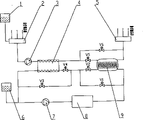
Fig. 1 is an enclosed Ice Storage Tank train of the present invention;
Fig. 2 is a band ice-melt finned coil open type Ice Storage Tank train of the present invention;
Fig. 3 is an open type Ice Storage Tank train of the present invention;
Fig. 4 is an enclosed Ice Storage Tank parallel system of the present invention;
Fig. 5 is a band ice-melt finned coil open type Ice Storage Tank parallel system of the present invention;
Fig. 6 is an open type Ice Storage Tank parallel system of the present invention.
Among the figure: 1. air conditioner water constant pressure arrangement, 2. water collector, 3. chilled water pump, 4. heat exchanger, 5. water knockout drum, 6. refrigerating medium constant pressure arrangement, 7. coolant pump, 8. refrigeration machine, 9. Ice Storage Tank, 10. CHP, 11. heat exchangers, V1, V2, V5, V6, V7, V8, V9, V10. electric control valve, V3, V4 electric switching valve.
The specific embodiment
Embodiment 1
Be that enclosed Ice Storage Tank train of the present invention comprises as shown in Figure 1:
1) refrigerating medium loop: the port of export of refrigeration machine 8 divides two-way, lead up to Ice Storage Tank 9 (among the figure for enclosed Ice Storage Tank) and electric control valve V2, lead up to electric control valve V1 bypass, be divided into two-way after converging again, the electric switching valve V4 of leading up to enters heat exchanger 4, lead up to electric switching valve V3, carry cryogen constant pressure arrangement 6 and coolant pump 7 after converging respectively, coolant pump 7 connects the arrival end of refrigeration machine 8; 2) air conditioner water loop: water collector 2 connects air conditioner water constant pressure arrangement 1, air-conditioning backwater, chilled water pump 3 respectively, the chilled water pump outlet is by being divided into two-way behind the heat exchanger 4, one the tunnel enters Ice Storage Tank 9 through electric control valve V5, and another road is converged with Ice Storage Tank 9 outlets after by electric control valve V6 and connect water knockout drum 5.
With enclosed Ice Storage Tank train is example, and it can finish following nine kinds of operational modes as requested:
1, when system operates in ice-make mode, in the refrigerating medium loop, refrigeration machine 8 and coolant pump 7 operations, electric control valve V1 and electric switching valve V4 close, and electric control valve V2 and electric switching valve V3 open; The air conditioner water loop quits work, and promptly chilled water pump [3] is out of service.In refrigerating medium loop, refrigerating medium enters refrigeration machine [8] through coolant pump [7] and enters in Ice Storage Tank [9] coil pipe after cooled, the water that cold is passed in the Ice Storage Tank 9 freezes it outside coil pipe, refrigerating medium after temperature raises returns coolant pump 7 through electric control valve V2, electric switching valve V3, enters next circulation.
2, operate in the refrigeration machine ice making cooling circulation time of holding concurrently when system, in the refrigerating medium loop, refrigeration machine 8 and coolant pump 7 operations, electric control valve V1 and electric switching valve V4 close, electric control valve V2 and electric switching valve V3 open, refrigerating medium enters refrigeration machine 8 through coolant pump 7 and enters in Ice Storage Tank 9 coil pipes after cooled, the water that cold is passed in the Ice Storage Tank 9 freezes it outside coil pipe, refrigerating medium after temperature raises returns coolant pump 7 through electric control valve V2, electric switching valve V3, enters next circulation.In the air-condition freezing water loop, chilled water pump 3 operations, high-temperature water from air-conditioner tail end equipment capable enters water collector 2, enter chilled water pump 3 then, enter Ice Storage Tank 9 through heat exchanger 4, electric control valve V5 again, the chilled water of high temperature is passed to ice in the Ice Storage Tank 9 with heat in Ice Storage Tank 9, melt the ice, air conditioning water after the cooling enters water knockout drum 5, by water knockout drum 5 cryogenic freezing water is delivered to air-conditioner tail end equipment capable, enters next circulation.Change ice-melt speed to satisfy the variation of load by regulating electric control valve V5, V6.
3, when system operate in single in during ice-melt mode, in the refrigerating medium loop, coolant pump 7 operations, refrigeration machine 8 is out of service, and electric switching valve V3 closes, and electric switching valve V4 opens, refrigerating medium enters refrigeration machine 8 through coolant pump 7 and enters in Ice Storage Tank 9 coil pipes again, Ice Storage Tank 9 is passed to the outer ice-out of coil pipe behind the refrigerating medium with cold, and the refrigerating medium after temperature reduces enters heat exchanger 4 through electric control valve V2, electric switching valve V4 and cold is passed to chilled water returns coolant pump 7 again, enters next circulation.Change ice-melt speed to satisfy the variation of load by regulating electric control valve V1 and V2.In the air-condition freezing water loop, chilled water pump 3 operations, electric control valve V5 closes, and electric control valve V6 opens, and enters water collector 2 from the high-temperature water of air-conditioner tail end equipment capable, enter chilled water pump 3 then, during through heat exchanger 4, heat is passed to refrigerating medium, chilled water is lowered the temperature after electric control valve V6 enters water knockout drum 5, by water knockout drum 5 cryogenic freezing water is delivered to air-conditioner tail end equipment capable, enter next circulation.
4, when system operated in single outer ice-melt mode, refrigerating medium loop was out of service, and promptly coolant pump 7 and refrigeration machine 8 are out of service.In the air-condition freezing water loop, chilled water pump 3 operations, high-temperature water from air-conditioner tail end equipment capable enters water collector 2, enter chilled water pump 3 then, enter Ice Storage Tank 9 through heat exchanger 4, electric control valve V5 again, the chilled water of high temperature is passed to ice in the Ice Storage Tank 9 with heat in Ice Storage Tank 9, melt the ice, air conditioning water after the cooling enters water knockout drum 5, by water knockout drum 5 cryogenic freezing water is delivered to air-conditioner tail end equipment capable, enters next circulation.Change ice-melt speed to satisfy the variation of load by regulating electric control valve V5, V6.
5, when system operates in single refrigeration machine cooling pattern, in the refrigerating medium loop, coolant pump 7 and refrigeration machine 8 operations, electric control valve V2, electric switching valve V3 close, electric control valve V1, electric switching valve V4 open, refrigerating medium enters heat exchanger 4 by electric control valve V1, electric switching valve V4 and cold is passed to chilled water returns coolant pump 7 again after coolant pump 7 enters refrigeration machine 8 cooling, enter next circulation.In the air-condition freezing water loop, chilled water pump 3 operations, electric control valve V5 closes, and electric control valve V6 opens, high-temperature water from air-conditioner tail end equipment capable enters water collector 2, enter chilled water pump 3 then, during through heat exchanger 4, heat is passed to refrigerating medium, the chilled water cooling is after electric control valve V6 enters water knockout drum 5, by water knockout drum 5 cryogenic freezing water is delivered to air-conditioner tail end equipment capable, enter next circulation, satisfy the variation of load by the refrigerating capacity of regulating refrigeration machine.
6, when system operates in refrigeration machine and interior ice-melt associating cooling pattern, in the refrigerating medium loop, coolant pump 7 and refrigeration machine [8] operation, electric switching valve V3 closes, electric switching valve V4 opens, refrigerating medium enters through coolant pump 7 and enters heat exchanger 4 by electric control valve V2, electric switching valve V4 again after refrigeration machine [8] cooling is lowered the temperature once more by Ice Storage Tank 9 inner coil pipes then and cold is passed to chilled water return coolant pump 7 again, enters next circulation.Change ice-melt speed to satisfy the variation of load by regulating electric control valve V1 and V2.In the air-condition freezing water loop, chilled water pump 3 operations, electric control valve V5 closes, and electric control valve V6 opens, and enters water collector 2 from the high-temperature water of air-conditioner tail end equipment capable, enter chilled water pump 3 then, during through heat exchanger 4, heat is passed to refrigerating medium, chilled water is lowered the temperature after electric control valve V6 enters water knockout drum 5, by water knockout drum 5 cryogenic freezing water is delivered to air-conditioner tail end equipment capable, enter next circulation.
7, when system operates in refrigeration machine and unites the cooling pattern with outer ice-melt, in the refrigerating medium loop, coolant pump 7 and refrigeration machine 8 operations, electric control valve V2, electric switching valve V3 close, electric control valve V1, electric switching valve V4 open, refrigerating medium enters heat exchanger 4 by electric control valve V1, electric switching valve V4 and cold is passed to chilled water returns coolant pump 7 again after coolant pump [7] enters refrigeration machine 8 cooling, enter next circulation.In the air-condition freezing water loop, chilled water pump 3 operations, high-temperature water from air-conditioner tail end equipment capable enters water collector 2, enter chilled water pump 3 then, during through heat exchanger 4, heat is passed to refrigerating medium, the chilled water cooling enters water knockout drum 5 after electric control valve V5 enters after Ice storage coiled pipe is lowered the temperature once more, by water knockout drum 5 cryogenic freezing water is delivered to air-conditioner tail end equipment capable, enter next circulation.Change ice-melt speed to satisfy the variation of load by regulating electric control valve V5, V6.
When 8, ice-melt is united the cooling pattern with outer ice-melt in system operates in, in the refrigerating medium loop, coolant pump 7 operations, refrigeration machine 8 is out of service, electric switching valve V3 closes, electric switching valve V4 opens, refrigerating medium enters refrigeration machine 8 through coolant pump 7 and enters in Ice Storage Tank 9 coil pipes again, Ice Storage Tank 9 is passed to the outer ice-out of coil pipe behind the refrigerating medium with cold, refrigerating medium after temperature reduces enters heat exchanger 4 through electric control valve V2, electric switching valve V4 and cold is passed to chilled water returns coolant pump 7 again, enters next circulation.In the air-condition freezing water loop, chilled water pump 3 operations, high-temperature water from air-conditioner tail end equipment capable enters water collector 2, enter chilled water pump 3 then, during through heat exchanger 4, heat is passed to refrigerating medium, the chilled water cooling enters water knockout drum 5 after electric control valve V5 enters after Ice Storage Tank 9 is lowered the temperature once more, by water knockout drum 5 cryogenic freezing water is delivered to air-conditioner tail end equipment capable, enter next circulation.Can regulate electric control valve V1, V2 changes interior ice-melt speed or regulates the variation that the outer ice-melt speed of electric control valve V5, V6 change satisfies load.
9, when system operate in refrigeration machine, when inside and outside ice-melt three unites the cooling pattern, in the refrigerating medium loop, coolant pump 7 and refrigeration machine 8 operations, electric switching valve V3 closes, electric switching valve V4 opens, refrigerating medium enters cooling once more in Ice Storage Tank 9 coil pipes after coolant pump 7 enters refrigeration machine 8 coolings, Ice Storage Tank 9 is passed to the outer ice-out of coil pipe behind the refrigerating medium with cold, refrigerating medium after temperature reduces enters heat exchanger 4 through electric control valve V2, electric switching valve V4 and cold is passed to chilled water returns coolant pump 7 again, enters next circulation.In the air-condition freezing water loop, chilled water pump 3 operations, high-temperature water from air-conditioner tail end equipment capable enters water collector 2, enter chilled water pump 3 then, during through heat exchanger 4, heat is passed to refrigerating medium, the chilled water cooling enters water knockout drum 5 after electric control valve V5 enters after Ice Storage Tank 9 is lowered the temperature once more, by water knockout drum 5 cryogenic freezing water is delivered to air-conditioner tail end equipment capable, enter next circulation.Can regulate electric control valve V1, V2 changes interior ice-melt speed or regulates the variation that the outer ice-melt speed of electric control valve V5, V6 change satisfies load.
For each equipment operation condition of enclosed Ice Storage Tank train clearly is described, as shown in table 1.
Embodiment 2
Be band ice-melt finned coil open type Ice Storage Tank train of the present invention as shown in Figure 2, comprise:
1) refrigerating medium loop: the port of export of refrigeration machine 8 divides two-way, lead up to Ice Storage Tank 9 (being band ice-melt finned coil open type Ice Storage Tank among the figure) and electric control valve V2, lead up to electric control valve V1 bypass, be divided into two-way after converging again, the electric switching valve V4 of leading up to enters heat exchanger 4, lead up to electric switching valve V3, carry cryogen constant pressure arrangement 6 and coolant pump 7 after converging respectively, coolant pump 7 connects the arrival end of refrigeration machine 8;
2) air conditioner water loop: water collector 2 connects air conditioner water constant pressure arrangement 1, air-conditioning backwater, chilled water pump 3 respectively, the chilled water pump outlet is by being divided into two-way behind the heat exchanger 4, one the tunnel enters Ice Storage Tank 9 through electric control valve V5, and another road is converged with Ice Storage Tank 9 outlets after by electric control valve V6 and connect water knockout drum 5.
For each equipment operation condition of band ice-melt finned coil open type Ice Storage Tank train clearly is described, as shown in table 2.
Embodiment 3
Be open type Ice Storage Tank train of the present invention as shown in Figure 3, comprise:
1) refrigerating medium loop: the port of export of refrigeration machine 8 divides two-way, lead up to Ice Storage Tank 9 and electric control valve V2, lead up to electric control valve V1 bypass, be divided into two-way after converging again, the electric switching valve V4 of leading up to enters first heat exchanger 4, lead up to electric switching valve V3, carry cryogen constant pressure arrangement 6 and coolant pump 7 after converging respectively, coolant pump 7 connects the arrival end of refrigeration machine 8;
2) air conditioner water loop: water collector 2 connects air conditioner water constant pressure arrangement 1, air-conditioning backwater, chilled water pump 3 respectively, and chilled water pump 3 outlets connect water knockout drum 5 by first heat exchanger 4, second heat exchanger 11 successively;
3) frozen water loop: CHP 10 connects second heat exchanger 11 and is divided into two-way then, and the electric control valve V7 of leading up to connects Ice Storage Tank 9, after another road process electric control valve V8 and Ice Storage Tank 9 outlets converge, connects CHP 10.
For each equipment operation condition of open type Ice Storage Tank train clearly is described, as shown in table 3.
Be enclosed Ice Storage Tank parallel system of the present invention as shown in Figure 4, comprise:
1) refrigerating medium loop: the port of export of refrigeration machine 8 divides two-way, lead up to Ice Storage Tank 9 (among the figure for enclosed Ice Storage Tank) and electric control valve V2, lead up to electric control valve V1 bypass, be divided into two-way after converging again, the electric switching valve V4 of leading up to enters heat exchanger 4, lead up to electric switching valve V3, carry cryogen constant pressure arrangement 6 and coolant pump 7 after converging respectively, coolant pump 7 connects the arrival end of refrigeration machine 8;
2) air conditioner water loop: water collector 2 connects air conditioner water constant pressure arrangement 1, air-conditioning backwater, chilled water pump 3 respectively, chilled water pump 3 outlets are divided into two-way, one the tunnel meets heat exchanger 4, electric control valve V9, two-way is divided again through electric control valve V10 in another road, the electric control valve V5 of leading up to enters Ice Storage Tank 9, after another road is converged by 9 outlets of electric control valve V6 and Ice Storage Tank, converge with electric control valve V9 outlet again and connect water knockout drum 5.
For each equipment operation condition of enclosed Ice Storage Tank parallel system clearly is described, as shown in table 4.
Embodiment 5
Be band ice-melt finned coil open type Ice Storage Tank parallel system of the present invention as shown in Figure 5, comprise:
1) refrigerating medium loop: the port of export of refrigeration machine 8 divides two-way, lead up to Ice Storage Tank 9 (being band ice-melt finned coil open type Ice Storage Tank among the figure) and electric control valve V2, lead up to electric control valve V1 bypass, be divided into two-way after converging again, the electric switching valve V4 of leading up to enters heat exchanger 4, lead up to electric switching valve V3, carry cryogen constant pressure arrangement 6 and coolant pump 7 after converging respectively, coolant pump 7 connects the arrival end of refrigeration machine 8;
2) air conditioner water loop: water collector 2 connects air conditioner water constant pressure arrangement 1, air-conditioning backwater, chilled water pump 3 respectively, chilled water pump 3 outlets are divided into two-way, one the tunnel meets heat exchanger 4, electric control valve V9, two-way is divided again through electric control valve V10 in another road, the electric control valve V5 of leading up to enters Ice Storage Tank 9, after another road is converged by 9 outlets of electric control valve V6 and Ice Storage Tank, converge with electric control valve V9 outlet again and connect water knockout drum 5.
For each equipment operation condition of band ice-melt finned coil open type Ice Storage Tank parallel system clearly is described, as shown in table 5.
Be open type Ice Storage Tank parallel system of the present invention as shown in Figure 6, comprise:
1) refrigerating medium loop: the port of export of refrigeration machine 8 divides two-way, lead up to Ice Storage Tank 9 and electric control valve V2, lead up to electric control valve V1 bypass, be divided into two-way after converging again, the electric switching valve V4 of leading up to enters first heat exchanger 4, lead up to electric switching valve V3, carry cryogen constant pressure arrangement 6 and coolant pump 7 after converging respectively, coolant pump 7 connects the arrival end of refrigeration machine 8;
2) air conditioner water loop: water collector 2 connects air conditioner water constant pressure arrangement 1, air-conditioning backwater, chilled water pump 3 respectively, chilled water pump 3 outlets are divided into two-way, one the tunnel meets first heat exchanger 4, electric control valve V5, and another road connects second heat exchanger 11 through electric control valve V6 and converges with electric control valve V5 outlet and connect water knockout drum 5;
3) frozen water loop: CHP 10 connects second heat exchanger 11 and is divided into two-way then, and the electric control valve V7 of leading up to enters Ice Storage Tank 9, connects CHP 10 after another road process electric control valve V8 and Ice Storage Tank 9 outlets converge.
For each equipment operation condition of open type Ice Storage Tank parallel system clearly is described, as shown in table 6.
Table 1: enclosed Ice Storage Tank train operation control table (as shown in Figure 1)
| Sequence number | Operational mode | Opening device | Open valve | Valve-off | Control valve |
| 1 | Ice making | Refrigeration machine, coolant pump | V2、V3 | V1、V4 | |
| 2 | The ice making cooling of holding concurrently | Refrigeration machine, coolant pump, chilled water pump | V2、V3 | V1、V4 | V5、V6 |
| 3 | Ice-melt in single | Coolant pump, chilled water pump | V4、V6 | V3、V5 | V1、 |
| 4 | Single outer ice-melt | Chilled water pump | V5、V6 | ||
| 5 | Single refrigeration machine cooling | Refrigeration machine, coolant pump, chilled water pump | V1、V4、V6 | V2、V3、 | |
| 6 | Refrigeration machine and interior ice-melt associating cooling | Refrigeration machine, coolant pump, chilled water pump | V4、V6 | V3、V5 | V1、 |
| 7 | Refrigeration machine and outer ice-melt associating cooling | Refrigeration machine, coolant pump, chilled water pump | V1、V4 | V2、V3 | V5、V6 |
| 8 | Interior ice-melt and outer ice-melt associating cooling | Coolant pump, chilled water pump | V4 | V3 | V1、V2、V5、 |
| 9 | Refrigeration machine, inside and outside ice-melt associating cooling | Refrigeration machine, coolant pump, chilled water pump | V4 | V3 | V1、V2、V5、 V6 |
Table 2: band ice-melt finned coil open type Ice Storage Tank train operation control table (as shown in Figure 2)
| Sequence number | Operational mode | Opening device | Open valve | Valve-off | Control valve |
| 1 | Ice making | Refrigeration machine, coolant pump | V2、V3 | V1、V4 | |
| 2 | The ice making cooling of holding concurrently | Refrigeration machine, coolant pump, chilled water pump | V2、V3 | V1、V4 | V5、V6 |
| 3 | Ice-melt in single | Coolant pump, chilled water pump | V4、V6 | V3、V5 | V1、 |
| 4 | Single outer ice-melt | Chilled water pump | V5、V6 | ||
| 5 | Single refrigeration machine cooling | Refrigeration machine, coolant pump, chilled water pump | V1、V4、V6 | V2、V3、 | |
| 6 | Refrigeration machine and interior ice-melt associating cooling | Refrigeration machine, coolant pump, chilled water pump | V4、V6 | V3、V5 | V1、 |
| 7 | Refrigeration machine and outer ice-melt associating cooling | Refrigeration machine, coolant pump, chilled water pump | V1、V4 | V2、V3 | V5、V6 |
| 8 | Interior ice-melt and outer ice-melt associating cooling | Coolant pump, chilled water pump | V4 | V3 | V1、V2、V5、 |
| 9 | Refrigeration machine, inside and outside ice-melt associating cooling | Refrigeration machine, coolant pump, chilled water pump | V4 | V3 | V1、V2、V5、 V6 |
Table 3: open type Ice Storage Tank train operation control table (as shown in Figure 3)
| Sequence number | Operational mode | Opening device | Open valve | Valve-off | Control valve |
| 1 | Ice making | Refrigeration machine, coolant pump | V2、V3 | V1、V4 | |
| 2 | The ice making cooling of holding concurrently | Refrigeration machine, coolant pump, chilled water pump, CHP | V2、V3 | V1、V4 | V7、V8 |
| 3 | Ice-melt in single | Coolant pump, chilled water pump | V4 | V3 | V1、 |
| 4 | Single outer ice-melt | Chilled water pump, CHP | V7、V8 | ||
| 5 | Single refrigeration machine cooling | Refrigeration machine, coolant pump, chilled water pump | V1、V4 | V2、 | |
| 6 | Refrigeration machine and interior ice-melt associating cooling | Refrigeration machine, coolant pump, chilled water pump | V4 | V3 | V1、 |
| 7 | Refrigeration machine and outer ice-melt associating cooling | Refrigeration machine, coolant pump, chilled water pump, CHP | V1、V4 | V2、V3 | V7、V8 |
| 8 | Interior ice-melt and outer ice-melt associating cooling | Coolant pump, chilled water pump, CHP | V4 | V3 | V1、V2、V7、 |
| 9 | Refrigeration machine, inside and outside ice-melt associating cooling | Refrigeration machine, coolant pump, chilled water pump, CHP | V4 | V3 | V1、V2、V7、 V8 |
Table 4: enclosed Ice Storage Tank parallel system operation control table (as shown in Figure 4)
| Sequence number | Operational mode | Opening device | Open valve | Valve-off | Control valve |
| 1 | Ice making | Refrigeration machine, coolant pump | V2、V3 | V1、V4 | |
| 2 | The ice making cooling of holding concurrently | Refrigeration machine, coolant pump, chilled water pump | V2、V3、V10 | V1、V4、V9 | V5、V6 |
| 3 | Ice-melt in single | Coolant pump, chilled water pump | V4、V9 | V3、V10 | V1、V2 |
| 4 | Single outer ice-melt | Chilled water pump | V10 | V9 | V5、V6 |
| 5 | Single refrigeration machine cooling | Refrigeration machine, coolant pump, chilled water pump | V1、V4、V9 | V2、V3、V10 | |
| 6 | Refrigeration machine and interior ice-melt associating cooling | Refrigeration machine, coolant pump, chilled water pump | V4、V9 | V3、V10 | V1、V2 |
| 7 | Refrigeration machine and outer ice-melt associating cooling | Refrigeration machine, coolant pump, chilled water pump | V1、V4、V10 | V2、V3、V9 | V5、V6 |
| 8 | Interior ice-melt and outer ice-melt associating cooling | Coolant pump, chilled water pump | V4 | V3 | V1、V2、V5、 V6、V9、V10 |
| 9 | Refrigeration machine, inside and outside ice-melt associating cooling | Refrigeration machine, coolant pump, chilled water pump | V4 | V3 | V1、V2、V5、 V6、V9、V10 |
Table 5: band ice-melt finned coil open type Ice Storage Tank parallel system operation control table (as shown in Figure 5)
| Sequence number | Operational mode | Opening device | Open valve | Valve-off | Control valve |
| 1 | Ice making | Refrigeration machine, coolant pump | V2、V3 | V1、V4 | |
| 2 | The ice making cooling of holding concurrently | Refrigeration machine, coolant pump, chilled water pump | V2、V3、V10 | V1、V4、V9 | V5、V6 |
| 3 | Ice-melt in single | Coolant pump, chilled water pump | V4、V9 | V3、V10 | V1、V2 |
| 4 | Single outer ice-melt | Chilled water pump | V10 | V9 | V5、V6 |
| 5 | Single refrigeration machine cooling | Refrigeration machine, coolant pump, chilled water pump | V1、V4、V9 | V2、V3、V10 | |
| 6 | Refrigeration machine and interior ice-melt associating cooling | Refrigeration machine, coolant pump, chilled water pump | V4、 V9 | V3、V10 | V1、V2 |
| 7 | Refrigeration machine and outer ice-melt associating cooling | Refrigeration machine, coolant pump, chilled water pump | V1、V4、V10 | V2、V3、V9 | V5、V6 |
| 8 | Interior ice-melt and outer ice-melt associating cooling | Coolant pump, chilled water pump | V4 | V3 | V1、V2、V5、 V6、V9、V10 |
| 9 | Refrigeration machine, inside and outside ice-melt associating cooling | Refrigeration machine, coolant pump, chilled water pump | V4 | V3 | V1、V2、V5、 V6、V9、V10 |
Table 6: open type Ice Storage Tank parallel system operation control table (as shown in Figure 6)
| Sequence number | Operational mode | Opening device | Open valve | Valve-off | Control valve |
| 1 | Ice making | Refrigeration machine, coolant pump | V2、V3 | V1、V4 | |
| 2 | The ice making cooling of holding concurrently | Refrigeration machine, coolant pump, chilled water pump, CHP | V2、V3、V6 | V1、V4、V5 | V7、V8 |
| 3 | Ice-melt in single | Coolant pump, chilled water pump | V4、V5 | V3、V6 | V1、V2 |
| 4 | Single outer ice-melt | Chilled water pump, CHP | V6 | V5 | V7、V8 |
| 5 | Single refrigeration machine cooling | Refrigeration machine, coolant pump, chilled water pump | V1、V4、V5 | V2、V3、V6 | |
| 6 | Refrigeration machine and interior ice-melt associating cooling | Refrigeration machine, coolant pump, chilled water pump | V4、V5 | V3、V6 | V1、V2 |
| 7 | Refrigeration machine and outer ice-melt associating cooling | Refrigeration machine, coolant pump, chilled water pump, CHP | V1、V4 | V2、V3 | V5、V6、V7、 V8 |
| 8 | Interior ice-melt and outer ice-melt associating cooling | Coolant pump, chilled water pump, CHP | V4 | V3 | V1、V2、V5、 V6、V7、V8 |
| 9 | Refrigeration machine, inside and outside ice-melt associating cooling | Refrigeration machine, coolant pump, chilled water pump, CHP | V4 | V3 | V1、V2、V5、 V6、V7、V8 |
Claims (6)
1, the ice-storage air-conditioning system that combines of a kind of inside and outside ice-melt comprises air conditioner water constant pressure arrangement (1), water collector (2), chilled water pump (3), first heat exchanger (4), water knockout drum (5), refrigerating medium constant pressure arrangement (6), coolant pump (7), refrigeration machine (8), Ice Storage Tank (9); It is characterized in that:
1) refrigerating medium loop: the port of export of refrigeration machine (8) divides two-way, lead up to Ice Storage Tank (9) and first electric control valve (V2), lead up to second electric control valve (V1) bypass, be divided into two-way after converging again, first electric switching valve (V4) of leading up to enters first heat exchanger (4), lead up to second electric switching valve (V3), carry cryogen constant pressure arrangement (6) and coolant pump (7) after converging respectively, coolant pump (7) connects the arrival end of refrigeration machine (8);
2) air conditioner water loop: water collector (2) connects air conditioner water constant pressure arrangement (1), air-conditioning backwater, chilled water pump (3) respectively, the chilled water pump outlet is by being divided into two-way behind first heat exchanger (4), one the tunnel enters Ice Storage Tank (9) through the 3rd electric control valve (V5), and another road is converged with Ice Storage Tank (9) outlet by the 4th electric control valve (V6) back and connect water knockout drum (5).
2, the ice-storage air-conditioning system that combines of a kind of inside and outside ice-melt according to claim 1, it is characterized in that: said Ice Storage Tank (9) is enclosed Ice Storage Tank or band ice-melt finned coil open type Ice Storage Tank.
3, the ice-storage air-conditioning system that combines of a kind of inside and outside ice-melt comprises air conditioner water constant pressure arrangement (1), water collector (2), chilled water pump (3), first heat exchanger (4), water knockout drum (5), refrigerating medium constant pressure arrangement (6), coolant pump (7), refrigeration machine (8), Ice Storage Tank (9), CHP (10), second heat exchanger (11); It is characterized in that:
1) refrigerating medium loop: the port of export of refrigeration machine (8) divides two-way, lead up to Ice Storage Tank (9) and first electric control valve (V2), lead up to second electric control valve (V1) bypass, be divided into two-way after converging again, first electric switching valve (V4) of leading up to enters first heat exchanger (4), lead up to second electric switching valve (V3), carry cryogen constant pressure arrangement (6) and coolant pump (7) after converging respectively, coolant pump (7) connects the arrival end of refrigeration machine (8);
2) air conditioner water loop: water collector (2) connects air conditioner water constant pressure arrangement (1), air-conditioning backwater, chilled water pump (3) respectively, and chilled water pump (3) outlet connects water knockout drum (5) by first heat exchanger (4), second heat exchanger (11) successively;
3) frozen water loop: CHP (10) connects second heat exchanger (11) and is divided into two-way then, the 5th electric control valve (V7) of leading up to connects Ice Storage Tank (9), another road connects CHP (10) after converging through the 6th electric control valve (V8) and Ice Storage Tank (9) outlet.
4, the ice-storage air-conditioning system that combines of a kind of inside and outside ice-melt comprises air conditioner water constant pressure arrangement (1), water collector (2), chilled water pump (3), first heat exchanger (4), water knockout drum (5), refrigerating medium constant pressure arrangement (6), coolant pump (7), refrigeration machine (8), Ice Storage Tank (9); It is characterized in that:
1) refrigerating medium loop: the port of export of refrigeration machine (8) divides two-way, lead up to Ice Storage Tank (9) and first electric control valve (V2), lead up to second electric control valve (V1) bypass, be divided into two-way after converging again, first electric switching valve (V4) of leading up to enters first heat exchanger (4), lead up to second electric switching valve (V3), carry cryogen constant pressure arrangement (6) and coolant pump (7) after converging respectively, coolant pump (7) connects the arrival end of refrigeration machine (8);
2) air conditioner water loop: water collector (2) connects air conditioner water constant pressure arrangement (1), air-conditioning backwater, chilled water pump (3) respectively, chilled water pump (3) outlet is divided into two-way, one the tunnel connects first heat exchanger (4), the 7th electric control valve (V9), another Lu Jingdi eight electric control valves (V10) divide two-way again, the 3rd electric control valve (V5) of leading up to enters Ice Storage Tank (9), after another road is converged by the outlet of the 4th electric control valve (V6) and Ice Storage Tank (9), converge with the 7th electric control valve (V9) outlet again and connect water knockout drum (5).
5, the ice-storage air-conditioning system that combines of a kind of inside and outside ice-melt according to claim 4, it is characterized in that: said Ice Storage Tank (9) is enclosed Ice Storage Tank or band ice-melt finned coil open type Ice Storage Tank.
6, the ice-storage air-conditioning system that combines of a kind of inside and outside ice-melt comprises air conditioner water constant pressure arrangement (1), water collector (2), chilled water pump (3), first heat exchanger (4), water knockout drum (5), refrigerating medium constant pressure arrangement (6), coolant pump (7), refrigeration machine (8), Ice Storage Tank (9), CHP (10), second heat exchanger (11); It is characterized in that:
1) refrigerating medium loop: the port of export of refrigeration machine (8) divides two-way, lead up to Ice Storage Tank (9) and first electric control valve (V2), lead up to second electric control valve (V1) bypass, be divided into two-way after converging again, first electric switching valve (V4) of leading up to enters first heat exchanger (4), lead up to second electric switching valve (V3), carry cryogen constant pressure arrangement (6) and coolant pump (7) after converging respectively, coolant pump (7) connects the arrival end of refrigeration machine (8);
2) air conditioner water loop: water collector (2) connects air conditioner water constant pressure arrangement (1), air-conditioning backwater, chilled water pump (3) respectively, chilled water pump (3) outlet is divided into two-way, one the tunnel connects first heat exchanger (4), the 3rd electric control valve (V5), and another Lu Jingdi four electric control valves (V6) connect the outlet of second heat exchanger (11) and the 3rd electric control valve (V5) and converge and connect water knockout drum (5);
3) frozen water loop: CHP (10) connects second heat exchanger (11) and is divided into two-way then, the 5th electric control valve (V7) of leading up to enters Ice Storage Tank (9), and another road connects CHP (10) after converging through the 6th electric control valve (V8) and Ice Storage Tank (9) outlet.
Priority Applications (1)
| Application Number | Priority Date | Filing Date | Title |
|---|---|---|---|
| CNB2004100170916A CN1247940C (en) | 2004-03-16 | 2004-03-16 | Ice storage air conditioning system cmbined with internally and externally melting ice |
Applications Claiming Priority (1)
| Application Number | Priority Date | Filing Date | Title |
|---|---|---|---|
| CNB2004100170916A CN1247940C (en) | 2004-03-16 | 2004-03-16 | Ice storage air conditioning system cmbined with internally and externally melting ice |
Publications (2)
| Publication Number | Publication Date |
|---|---|
| CN1563814A CN1563814A (en) | 2005-01-12 |
| CN1247940C true CN1247940C (en) | 2006-03-29 |
Family
ID=34478769
Family Applications (1)
| Application Number | Title | Priority Date | Filing Date |
|---|---|---|---|
| CNB2004100170916A Expired - Fee Related CN1247940C (en) | 2004-03-16 | 2004-03-16 | Ice storage air conditioning system cmbined with internally and externally melting ice |
Country Status (1)
| Country | Link |
|---|---|
| CN (1) | CN1247940C (en) |
Families Citing this family (3)
| Publication number | Priority date | Publication date | Assignee | Title |
|---|---|---|---|---|
| CN106524360A (en) * | 2016-04-26 | 2017-03-22 | 珠海格力电器股份有限公司 | Control method of ice storage air conditioning system |
| CN106765449A (en) * | 2016-12-31 | 2017-05-31 | 青岛科创蓝新能源股份有限公司 | A kind of latent heat of solidification harvester and system |
| CN110160244A (en) * | 2019-06-24 | 2019-08-23 | 浙江大冲能源科技有限公司 | A kind of balanced energy conservation control device based on central air-conditioning secondary pumping system |
-
2004
- 2004-03-16 CN CNB2004100170916A patent/CN1247940C/en not_active Expired - Fee Related
Also Published As
| Publication number | Publication date |
|---|---|
| CN1563814A (en) | 2005-01-12 |
Similar Documents
| Publication | Publication Date | Title |
|---|---|---|
| CN101334203B (en) | Method for enhancing cold-storage density of cold storage air conditioner system and cold storage air conditioner system | |
| CN1924473A (en) | Temperature and humidity individual control air conditioner system | |
| CN104896641A (en) | Double-evaporator dynamic ice cold storage system | |
| CN104791925A (en) | Energy-saving type open cold supply system for cooling tower | |
| CN109855218B (en) | Integrated closed evaporative cooling-condensation water chilling unit | |
| CN204555111U (en) | Energy-saving open cooling tower cold supply system | |
| CN102313331A (en) | Ice storage refrigeration system and refrigeration method thereof | |
| EP3631340A1 (en) | Systems with multi-circuited, phase-change composite heat exchangers | |
| CN105910458B (en) | Three dimension high efficiency evaporation and heat-exchange system | |
| CN105115079B (en) | A kind of central air-conditioning chilled water storage system | |
| CN201844488U (en) | External ice-thawing type cold accumulation system | |
| CN204730381U (en) | Double evaporators dynamic ice cold storage system | |
| CN202119028U (en) | Evaporative cooling closed high-temperature cold water machine set with mechanical refrigeration as auxiliary cold source | |
| CN1247940C (en) | Ice storage air conditioning system cmbined with internally and externally melting ice | |
| CN101713579B (en) | Open low-temperature heat source refrigerating system | |
| CN2684060Y (en) | Inside and outside sleet melting combined ice storage air conditioning system | |
| CN207881055U (en) | A kind of dynamic ice cold-storage air-conditioning system | |
| CN2830985Y (en) | Ice storage air conditioning system | |
| CN206317647U (en) | A kind of battery thermal management system based on pure electric heat pump air-conditioning | |
| CN112254236B (en) | Indirect evaporative cooling cold water system combining mechanical refrigeration and switching method | |
| CN104807248B (en) | A kind of centralized cold and heat source system for workshop circulation | |
| CN2562109Y (en) | Direct distilling closed air conditioner with external ice melting heat pump | |
| CN203704490U (en) | Environment-friendly commercial refrigeration system | |
| CN202109600U (en) | Semiconductor air conditioner with high refrigeration efficiency | |
| CN202281328U (en) | Ice storage refrigeration system |
Legal Events
| Date | Code | Title | Description |
|---|---|---|---|
| C06 | Publication | ||
| PB01 | Publication | ||
| C10 | Entry into substantive examination | ||
| SE01 | Entry into force of request for substantive examination | ||
| C14 | Grant of patent or utility model | ||
| GR01 | Patent grant | ||
| C17 | Cessation of patent right | ||
| CF01 | Termination of patent right due to non-payment of annual fee |
Granted publication date: 20060329 Termination date: 20130316 |