CN1246384A - Ceramic membrane for endothermic reaction - Google Patents
Ceramic membrane for endothermic reaction Download PDFInfo
- Publication number
- CN1246384A CN1246384A CN99118184A CN99118184A CN1246384A CN 1246384 A CN1246384 A CN 1246384A CN 99118184 A CN99118184 A CN 99118184A CN 99118184 A CN99118184 A CN 99118184A CN 1246384 A CN1246384 A CN 1246384A
- Authority
- CN
- China
- Prior art keywords
- oxygen
- tube
- fuel
- ion transport
- combustion
- Prior art date
- Legal status (The legal status is an assumption and is not a legal conclusion. Google has not performed a legal analysis and makes no representation as to the accuracy of the status listed.)
- Pending
Links
Images


Classifications
-
- H—ELECTRICITY
- H01—ELECTRIC ELEMENTS
- H01M—PROCESSES OR MEANS, e.g. BATTERIES, FOR THE DIRECT CONVERSION OF CHEMICAL ENERGY INTO ELECTRICAL ENERGY
- H01M8/00—Fuel cells; Manufacture thereof
- H01M8/06—Combination of fuel cells with means for production of reactants or for treatment of residues
-
- B—PERFORMING OPERATIONS; TRANSPORTING
- B01—PHYSICAL OR CHEMICAL PROCESSES OR APPARATUS IN GENERAL
- B01J—CHEMICAL OR PHYSICAL PROCESSES, e.g. CATALYSIS OR COLLOID CHEMISTRY; THEIR RELEVANT APPARATUS
- B01J12/00—Chemical processes in general for reacting gaseous media with gaseous media; Apparatus specially adapted therefor
- B01J12/007—Chemical processes in general for reacting gaseous media with gaseous media; Apparatus specially adapted therefor in the presence of catalytically active bodies, e.g. porous plates
-
- B—PERFORMING OPERATIONS; TRANSPORTING
- B01—PHYSICAL OR CHEMICAL PROCESSES OR APPARATUS IN GENERAL
- B01D—SEPARATION
- B01D61/00—Processes of separation using semi-permeable membranes, e.g. dialysis, osmosis or ultrafiltration; Apparatus, accessories or auxiliary operations specially adapted therefor
-
- B—PERFORMING OPERATIONS; TRANSPORTING
- B01—PHYSICAL OR CHEMICAL PROCESSES OR APPARATUS IN GENERAL
- B01J—CHEMICAL OR PHYSICAL PROCESSES, e.g. CATALYSIS OR COLLOID CHEMISTRY; THEIR RELEVANT APPARATUS
- B01J19/00—Chemical, physical or physico-chemical processes in general; Their relevant apparatus
- B01J19/24—Stationary reactors without moving elements inside
- B01J19/2415—Tubular reactors
- B01J19/2425—Tubular reactors in parallel
-
- B—PERFORMING OPERATIONS; TRANSPORTING
- B01—PHYSICAL OR CHEMICAL PROCESSES OR APPARATUS IN GENERAL
- B01J—CHEMICAL OR PHYSICAL PROCESSES, e.g. CATALYSIS OR COLLOID CHEMISTRY; THEIR RELEVANT APPARATUS
- B01J19/00—Chemical, physical or physico-chemical processes in general; Their relevant apparatus
- B01J19/24—Stationary reactors without moving elements inside
- B01J19/2475—Membrane reactors
-
- B—PERFORMING OPERATIONS; TRANSPORTING
- B01—PHYSICAL OR CHEMICAL PROCESSES OR APPARATUS IN GENERAL
- B01J—CHEMICAL OR PHYSICAL PROCESSES, e.g. CATALYSIS OR COLLOID CHEMISTRY; THEIR RELEVANT APPARATUS
- B01J8/00—Chemical or physical processes in general, conducted in the presence of fluids and solid particles; Apparatus for such processes
- B01J8/008—Details of the reactor or of the particulate material; Processes to increase or to retard the rate of reaction
- B01J8/009—Membranes, e.g. feeding or removing reactants or products to or from the catalyst bed through a membrane
-
- B—PERFORMING OPERATIONS; TRANSPORTING
- B01—PHYSICAL OR CHEMICAL PROCESSES OR APPARATUS IN GENERAL
- B01J—CHEMICAL OR PHYSICAL PROCESSES, e.g. CATALYSIS OR COLLOID CHEMISTRY; THEIR RELEVANT APPARATUS
- B01J8/00—Chemical or physical processes in general, conducted in the presence of fluids and solid particles; Apparatus for such processes
- B01J8/02—Chemical or physical processes in general, conducted in the presence of fluids and solid particles; Apparatus for such processes with stationary particles, e.g. in fixed beds
- B01J8/0242—Chemical or physical processes in general, conducted in the presence of fluids and solid particles; Apparatus for such processes with stationary particles, e.g. in fixed beds the fluid flow within the bed being predominantly vertical
- B01J8/025—Chemical or physical processes in general, conducted in the presence of fluids and solid particles; Apparatus for such processes with stationary particles, e.g. in fixed beds the fluid flow within the bed being predominantly vertical in a cylindrical shaped bed
-
- B—PERFORMING OPERATIONS; TRANSPORTING
- B01—PHYSICAL OR CHEMICAL PROCESSES OR APPARATUS IN GENERAL
- B01J—CHEMICAL OR PHYSICAL PROCESSES, e.g. CATALYSIS OR COLLOID CHEMISTRY; THEIR RELEVANT APPARATUS
- B01J8/00—Chemical or physical processes in general, conducted in the presence of fluids and solid particles; Apparatus for such processes
- B01J8/02—Chemical or physical processes in general, conducted in the presence of fluids and solid particles; Apparatus for such processes with stationary particles, e.g. in fixed beds
- B01J8/0242—Chemical or physical processes in general, conducted in the presence of fluids and solid particles; Apparatus for such processes with stationary particles, e.g. in fixed beds the fluid flow within the bed being predominantly vertical
- B01J8/0257—Chemical or physical processes in general, conducted in the presence of fluids and solid particles; Apparatus for such processes with stationary particles, e.g. in fixed beds the fluid flow within the bed being predominantly vertical in a cylindrical annular shaped bed
-
- B—PERFORMING OPERATIONS; TRANSPORTING
- B01—PHYSICAL OR CHEMICAL PROCESSES OR APPARATUS IN GENERAL
- B01J—CHEMICAL OR PHYSICAL PROCESSES, e.g. CATALYSIS OR COLLOID CHEMISTRY; THEIR RELEVANT APPARATUS
- B01J8/00—Chemical or physical processes in general, conducted in the presence of fluids and solid particles; Apparatus for such processes
- B01J8/02—Chemical or physical processes in general, conducted in the presence of fluids and solid particles; Apparatus for such processes with stationary particles, e.g. in fixed beds
- B01J8/0278—Feeding reactive fluids
-
- B—PERFORMING OPERATIONS; TRANSPORTING
- B01—PHYSICAL OR CHEMICAL PROCESSES OR APPARATUS IN GENERAL
- B01J—CHEMICAL OR PHYSICAL PROCESSES, e.g. CATALYSIS OR COLLOID CHEMISTRY; THEIR RELEVANT APPARATUS
- B01J8/00—Chemical or physical processes in general, conducted in the presence of fluids and solid particles; Apparatus for such processes
- B01J8/02—Chemical or physical processes in general, conducted in the presence of fluids and solid particles; Apparatus for such processes with stationary particles, e.g. in fixed beds
- B01J8/06—Chemical or physical processes in general, conducted in the presence of fluids and solid particles; Apparatus for such processes with stationary particles, e.g. in fixed beds in tube reactors; the solid particles being arranged in tubes
- B01J8/067—Heating or cooling the reactor
-
- C—CHEMISTRY; METALLURGY
- C01—INORGANIC CHEMISTRY
- C01B—NON-METALLIC ELEMENTS; COMPOUNDS THEREOF; METALLOIDS OR COMPOUNDS THEREOF NOT COVERED BY SUBCLASS C01C
- C01B13/00—Oxygen; Ozone; Oxides or hydroxides in general
- C01B13/02—Preparation of oxygen
- C01B13/0229—Purification or separation processes
- C01B13/0248—Physical processing only
- C01B13/0251—Physical processing only by making use of membranes
-
- C—CHEMISTRY; METALLURGY
- C01—INORGANIC CHEMISTRY
- C01B—NON-METALLIC ELEMENTS; COMPOUNDS THEREOF; METALLOIDS OR COMPOUNDS THEREOF NOT COVERED BY SUBCLASS C01C
- C01B3/00—Hydrogen; Gaseous mixtures containing hydrogen; Separation of hydrogen from mixtures containing it; Purification of hydrogen
- C01B3/02—Production of hydrogen or of gaseous mixtures containing a substantial proportion of hydrogen
- C01B3/32—Production of hydrogen or of gaseous mixtures containing a substantial proportion of hydrogen by reaction of gaseous or liquid organic compounds with gasifying agents, e.g. water, carbon dioxide, air
- C01B3/34—Production of hydrogen or of gaseous mixtures containing a substantial proportion of hydrogen by reaction of gaseous or liquid organic compounds with gasifying agents, e.g. water, carbon dioxide, air by reaction of hydrocarbons with gasifying agents
- C01B3/38—Production of hydrogen or of gaseous mixtures containing a substantial proportion of hydrogen by reaction of gaseous or liquid organic compounds with gasifying agents, e.g. water, carbon dioxide, air by reaction of hydrocarbons with gasifying agents using catalysts
- C01B3/382—Multi-step processes
-
- C—CHEMISTRY; METALLURGY
- C01—INORGANIC CHEMISTRY
- C01B—NON-METALLIC ELEMENTS; COMPOUNDS THEREOF; METALLOIDS OR COMPOUNDS THEREOF NOT COVERED BY SUBCLASS C01C
- C01B3/00—Hydrogen; Gaseous mixtures containing hydrogen; Separation of hydrogen from mixtures containing it; Purification of hydrogen
- C01B3/02—Production of hydrogen or of gaseous mixtures containing a substantial proportion of hydrogen
- C01B3/32—Production of hydrogen or of gaseous mixtures containing a substantial proportion of hydrogen by reaction of gaseous or liquid organic compounds with gasifying agents, e.g. water, carbon dioxide, air
- C01B3/34—Production of hydrogen or of gaseous mixtures containing a substantial proportion of hydrogen by reaction of gaseous or liquid organic compounds with gasifying agents, e.g. water, carbon dioxide, air by reaction of hydrocarbons with gasifying agents
- C01B3/38—Production of hydrogen or of gaseous mixtures containing a substantial proportion of hydrogen by reaction of gaseous or liquid organic compounds with gasifying agents, e.g. water, carbon dioxide, air by reaction of hydrocarbons with gasifying agents using catalysts
- C01B3/384—Production of hydrogen or of gaseous mixtures containing a substantial proportion of hydrogen by reaction of gaseous or liquid organic compounds with gasifying agents, e.g. water, carbon dioxide, air by reaction of hydrocarbons with gasifying agents using catalysts the catalyst being continuously externally heated
-
- B—PERFORMING OPERATIONS; TRANSPORTING
- B01—PHYSICAL OR CHEMICAL PROCESSES OR APPARATUS IN GENERAL
- B01J—CHEMICAL OR PHYSICAL PROCESSES, e.g. CATALYSIS OR COLLOID CHEMISTRY; THEIR RELEVANT APPARATUS
- B01J2208/00—Processes carried out in the presence of solid particles; Reactors therefor
- B01J2208/00008—Controlling the process
- B01J2208/00017—Controlling the temperature
- B01J2208/00106—Controlling the temperature by indirect heat exchange
- B01J2208/00168—Controlling the temperature by indirect heat exchange with heat exchange elements outside the bed of solid particles
- B01J2208/00212—Plates; Jackets; Cylinders
- B01J2208/00221—Plates; Jackets; Cylinders comprising baffles for guiding the flow of the heat exchange medium
-
- B—PERFORMING OPERATIONS; TRANSPORTING
- B01—PHYSICAL OR CHEMICAL PROCESSES OR APPARATUS IN GENERAL
- B01J—CHEMICAL OR PHYSICAL PROCESSES, e.g. CATALYSIS OR COLLOID CHEMISTRY; THEIR RELEVANT APPARATUS
- B01J2208/00—Processes carried out in the presence of solid particles; Reactors therefor
- B01J2208/00008—Controlling the process
- B01J2208/00017—Controlling the temperature
- B01J2208/00106—Controlling the temperature by indirect heat exchange
- B01J2208/00309—Controlling the temperature by indirect heat exchange with two or more reactions in heat exchange with each other, such as an endothermic reaction in heat exchange with an exothermic reaction
-
- B—PERFORMING OPERATIONS; TRANSPORTING
- B01—PHYSICAL OR CHEMICAL PROCESSES OR APPARATUS IN GENERAL
- B01J—CHEMICAL OR PHYSICAL PROCESSES, e.g. CATALYSIS OR COLLOID CHEMISTRY; THEIR RELEVANT APPARATUS
- B01J2208/00—Processes carried out in the presence of solid particles; Reactors therefor
- B01J2208/00008—Controlling the process
- B01J2208/00017—Controlling the temperature
- B01J2208/00477—Controlling the temperature by thermal insulation means
- B01J2208/00495—Controlling the temperature by thermal insulation means using insulating materials or refractories
-
- B—PERFORMING OPERATIONS; TRANSPORTING
- B01—PHYSICAL OR CHEMICAL PROCESSES OR APPARATUS IN GENERAL
- B01J—CHEMICAL OR PHYSICAL PROCESSES, e.g. CATALYSIS OR COLLOID CHEMISTRY; THEIR RELEVANT APPARATUS
- B01J2208/00—Processes carried out in the presence of solid particles; Reactors therefor
- B01J2208/00008—Controlling the process
- B01J2208/00017—Controlling the temperature
- B01J2208/00504—Controlling the temperature by means of a burner
-
- B—PERFORMING OPERATIONS; TRANSPORTING
- B01—PHYSICAL OR CHEMICAL PROCESSES OR APPARATUS IN GENERAL
- B01J—CHEMICAL OR PHYSICAL PROCESSES, e.g. CATALYSIS OR COLLOID CHEMISTRY; THEIR RELEVANT APPARATUS
- B01J2208/00—Processes carried out in the presence of solid particles; Reactors therefor
- B01J2208/00008—Controlling the process
- B01J2208/00017—Controlling the temperature
- B01J2208/0053—Controlling multiple zones along the direction of flow, e.g. pre-heating and after-cooling
-
- B—PERFORMING OPERATIONS; TRANSPORTING
- B01—PHYSICAL OR CHEMICAL PROCESSES OR APPARATUS IN GENERAL
- B01J—CHEMICAL OR PHYSICAL PROCESSES, e.g. CATALYSIS OR COLLOID CHEMISTRY; THEIR RELEVANT APPARATUS
- B01J2208/00—Processes carried out in the presence of solid particles; Reactors therefor
- B01J2208/00008—Controlling the process
- B01J2208/00539—Pressure
-
- B—PERFORMING OPERATIONS; TRANSPORTING
- B01—PHYSICAL OR CHEMICAL PROCESSES OR APPARATUS IN GENERAL
- B01J—CHEMICAL OR PHYSICAL PROCESSES, e.g. CATALYSIS OR COLLOID CHEMISTRY; THEIR RELEVANT APPARATUS
- B01J2208/00—Processes carried out in the presence of solid particles; Reactors therefor
- B01J2208/00008—Controlling the process
- B01J2208/00548—Flow
-
- B—PERFORMING OPERATIONS; TRANSPORTING
- B01—PHYSICAL OR CHEMICAL PROCESSES OR APPARATUS IN GENERAL
- B01J—CHEMICAL OR PHYSICAL PROCESSES, e.g. CATALYSIS OR COLLOID CHEMISTRY; THEIR RELEVANT APPARATUS
- B01J2208/00—Processes carried out in the presence of solid particles; Reactors therefor
- B01J2208/00008—Controlling the process
- B01J2208/00628—Controlling the composition of the reactive mixture
-
- B—PERFORMING OPERATIONS; TRANSPORTING
- B01—PHYSICAL OR CHEMICAL PROCESSES OR APPARATUS IN GENERAL
- B01J—CHEMICAL OR PHYSICAL PROCESSES, e.g. CATALYSIS OR COLLOID CHEMISTRY; THEIR RELEVANT APPARATUS
- B01J2219/00—Chemical, physical or physico-chemical processes in general; Their relevant apparatus
- B01J2219/00049—Controlling or regulating processes
- B01J2219/00051—Controlling the temperature
- B01J2219/00074—Controlling the temperature by indirect heating or cooling employing heat exchange fluids
- B01J2219/00117—Controlling the temperature by indirect heating or cooling employing heat exchange fluids with two or more reactions in heat exchange with each other, such as an endothermic reaction in heat exchange with an exothermic reaction
-
- B—PERFORMING OPERATIONS; TRANSPORTING
- B01—PHYSICAL OR CHEMICAL PROCESSES OR APPARATUS IN GENERAL
- B01J—CHEMICAL OR PHYSICAL PROCESSES, e.g. CATALYSIS OR COLLOID CHEMISTRY; THEIR RELEVANT APPARATUS
- B01J2219/00—Chemical, physical or physico-chemical processes in general; Their relevant apparatus
- B01J2219/00049—Controlling or regulating processes
- B01J2219/00051—Controlling the temperature
- B01J2219/0015—Controlling the temperature by thermal insulation means
- B01J2219/00155—Controlling the temperature by thermal insulation means using insulating materials or refractories
-
- B—PERFORMING OPERATIONS; TRANSPORTING
- B01—PHYSICAL OR CHEMICAL PROCESSES OR APPARATUS IN GENERAL
- B01J—CHEMICAL OR PHYSICAL PROCESSES, e.g. CATALYSIS OR COLLOID CHEMISTRY; THEIR RELEVANT APPARATUS
- B01J2219/00—Chemical, physical or physico-chemical processes in general; Their relevant apparatus
- B01J2219/00049—Controlling or regulating processes
- B01J2219/00051—Controlling the temperature
- B01J2219/00159—Controlling the temperature controlling multiple zones along the direction of flow, e.g. pre-heating and after-cooling
-
- B—PERFORMING OPERATIONS; TRANSPORTING
- B01—PHYSICAL OR CHEMICAL PROCESSES OR APPARATUS IN GENERAL
- B01J—CHEMICAL OR PHYSICAL PROCESSES, e.g. CATALYSIS OR COLLOID CHEMISTRY; THEIR RELEVANT APPARATUS
- B01J2219/00—Chemical, physical or physico-chemical processes in general; Their relevant apparatus
- B01J2219/00049—Controlling or regulating processes
- B01J2219/00162—Controlling or regulating processes controlling the pressure
-
- B—PERFORMING OPERATIONS; TRANSPORTING
- B01—PHYSICAL OR CHEMICAL PROCESSES OR APPARATUS IN GENERAL
- B01J—CHEMICAL OR PHYSICAL PROCESSES, e.g. CATALYSIS OR COLLOID CHEMISTRY; THEIR RELEVANT APPARATUS
- B01J2219/00—Chemical, physical or physico-chemical processes in general; Their relevant apparatus
- B01J2219/00049—Controlling or regulating processes
- B01J2219/00186—Controlling or regulating processes controlling the composition of the reactive mixture
-
- B—PERFORMING OPERATIONS; TRANSPORTING
- B01—PHYSICAL OR CHEMICAL PROCESSES OR APPARATUS IN GENERAL
- B01J—CHEMICAL OR PHYSICAL PROCESSES, e.g. CATALYSIS OR COLLOID CHEMISTRY; THEIR RELEVANT APPARATUS
- B01J2219/00—Chemical, physical or physico-chemical processes in general; Their relevant apparatus
- B01J2219/00761—Details of the reactor
- B01J2219/00763—Baffles
- B01J2219/00765—Baffles attached to the reactor wall
- B01J2219/00777—Baffles attached to the reactor wall horizontal
-
- C—CHEMISTRY; METALLURGY
- C01—INORGANIC CHEMISTRY
- C01B—NON-METALLIC ELEMENTS; COMPOUNDS THEREOF; METALLOIDS OR COMPOUNDS THEREOF NOT COVERED BY SUBCLASS C01C
- C01B2203/00—Integrated processes for the production of hydrogen or synthesis gas
- C01B2203/02—Processes for making hydrogen or synthesis gas
- C01B2203/0205—Processes for making hydrogen or synthesis gas containing a reforming step
- C01B2203/0227—Processes for making hydrogen or synthesis gas containing a reforming step containing a catalytic reforming step
- C01B2203/0233—Processes for making hydrogen or synthesis gas containing a reforming step containing a catalytic reforming step the reforming step being a steam reforming step
-
- C—CHEMISTRY; METALLURGY
- C01—INORGANIC CHEMISTRY
- C01B—NON-METALLIC ELEMENTS; COMPOUNDS THEREOF; METALLOIDS OR COMPOUNDS THEREOF NOT COVERED BY SUBCLASS C01C
- C01B2203/00—Integrated processes for the production of hydrogen or synthesis gas
- C01B2203/06—Integration with other chemical processes
- C01B2203/066—Integration with other chemical processes with fuel cells
-
- C—CHEMISTRY; METALLURGY
- C01—INORGANIC CHEMISTRY
- C01B—NON-METALLIC ELEMENTS; COMPOUNDS THEREOF; METALLOIDS OR COMPOUNDS THEREOF NOT COVERED BY SUBCLASS C01C
- C01B2203/00—Integrated processes for the production of hydrogen or synthesis gas
- C01B2203/08—Methods of heating or cooling
- C01B2203/0805—Methods of heating the process for making hydrogen or synthesis gas
- C01B2203/0811—Methods of heating the process for making hydrogen or synthesis gas by combustion of fuel
-
- C—CHEMISTRY; METALLURGY
- C01—INORGANIC CHEMISTRY
- C01B—NON-METALLIC ELEMENTS; COMPOUNDS THEREOF; METALLOIDS OR COMPOUNDS THEREOF NOT COVERED BY SUBCLASS C01C
- C01B2203/00—Integrated processes for the production of hydrogen or synthesis gas
- C01B2203/14—Details of the flowsheet
- C01B2203/141—At least two reforming, decomposition or partial oxidation steps in parallel
-
- C—CHEMISTRY; METALLURGY
- C01—INORGANIC CHEMISTRY
- C01B—NON-METALLIC ELEMENTS; COMPOUNDS THEREOF; METALLOIDS OR COMPOUNDS THEREOF NOT COVERED BY SUBCLASS C01C
- C01B2203/00—Integrated processes for the production of hydrogen or synthesis gas
- C01B2203/14—Details of the flowsheet
- C01B2203/142—At least two reforming, decomposition or partial oxidation steps in series
-
- C—CHEMISTRY; METALLURGY
- C01—INORGANIC CHEMISTRY
- C01B—NON-METALLIC ELEMENTS; COMPOUNDS THEREOF; METALLOIDS OR COMPOUNDS THEREOF NOT COVERED BY SUBCLASS C01C
- C01B2203/00—Integrated processes for the production of hydrogen or synthesis gas
- C01B2203/14—Details of the flowsheet
- C01B2203/148—Details of the flowsheet involving a recycle stream to the feed of the process for making hydrogen or synthesis gas
-
- C—CHEMISTRY; METALLURGY
- C01—INORGANIC CHEMISTRY
- C01B—NON-METALLIC ELEMENTS; COMPOUNDS THEREOF; METALLOIDS OR COMPOUNDS THEREOF NOT COVERED BY SUBCLASS C01C
- C01B2203/00—Integrated processes for the production of hydrogen or synthesis gas
- C01B2203/80—Aspect of integrated processes for the production of hydrogen or synthesis gas not covered by groups C01B2203/02 - C01B2203/1695
- C01B2203/82—Several process steps of C01B2203/02 - C01B2203/08 integrated into a single apparatus
-
- C—CHEMISTRY; METALLURGY
- C01—INORGANIC CHEMISTRY
- C01B—NON-METALLIC ELEMENTS; COMPOUNDS THEREOF; METALLOIDS OR COMPOUNDS THEREOF NOT COVERED BY SUBCLASS C01C
- C01B2210/00—Purification or separation of specific gases
- C01B2210/0043—Impurity removed
- C01B2210/0046—Nitrogen
-
- Y—GENERAL TAGGING OF NEW TECHNOLOGICAL DEVELOPMENTS; GENERAL TAGGING OF CROSS-SECTIONAL TECHNOLOGIES SPANNING OVER SEVERAL SECTIONS OF THE IPC; TECHNICAL SUBJECTS COVERED BY FORMER USPC CROSS-REFERENCE ART COLLECTIONS [XRACs] AND DIGESTS
- Y02—TECHNOLOGIES OR APPLICATIONS FOR MITIGATION OR ADAPTATION AGAINST CLIMATE CHANGE
- Y02E—REDUCTION OF GREENHOUSE GAS [GHG] EMISSIONS, RELATED TO ENERGY GENERATION, TRANSMISSION OR DISTRIBUTION
- Y02E60/00—Enabling technologies; Technologies with a potential or indirect contribution to GHG emissions mitigation
- Y02E60/30—Hydrogen technology
- Y02E60/50—Fuel cells
Abstract
Syngas, a mixture of hydrogen and carbon monoxide, is an intermediate in the conversion of methane to liquid fuels. For certain applications, it is desirable to maintain an H2/CO molar ratio of about 3. This molar ratio is achieved by steam reforming of methane in accordance with: CH4 + H2O -> 3H2 + CO. To provide the heat required to drive the endothermic steam reforming reaction, a low grade fuel is combusted in a reactor and the heat of combustion conducted to the endothermic reaction. By using an oxygen selective ion transport membrane element to transport the oxygen required for combustion, the formation of undesirable NOx compounds is minimized.
Description
This patent application is a continuation-in-part application filed on 3.6.1998 and entitled U.S. patent application No. 09/089,372 entitled synthesis gas reactor with ceramic membranes, the entire contents of which are incorporated herein by reference.
The present invention relates to a process for producing a product gas, such as synthesis gas or unsaturated hydrocarbons, in a reactor by an endothermic steam reforming reaction. The heat energy to sustain the endothermic reaction is generated by combustion of the fuel with oxygen, which is obtained from the permeate or retentate fraction after gas separation by contacting the oxygen-containing gas with an oxygen-selective ion transport membrane.
It is difficult to economically transport natural gas and methane-the major component of natural gas, and it is not easy to convert it into liquid fuels or chemicals, such as gasoline, methanol, formaldehyde and olefins, which are relatively easy to store and transport. For ease of transportation, methane is typically converted to synthesis gas (syngas), which is an intermediate in the conversion of methane to liquid fuels, methanol, or other chemicals. The synthesis gas is a mixture of hydrogen and carbon monoxide, H thereof2The molar ratio/CO is from about 0.6 to about 6.
One effective chemical reaction for converting methane to syngas is steam reforming. Methane is reacted with steam and endothermically converted to a mixture of hydrogen and carbon monoxide. The heat energy to sustain the endothermic reaction is generated by external combustion of fuel. The reaction formula of the steam reforming reaction is
The second effective chemical reaction to convert methane to syngas is partial oxidation. Methane reacts exothermically with oxygen according to the formula: (2) generation of H2Synthesis gas with a molar ratio/CO of 2.
U.S. patent 5,306,411 to mazanick et al, which is incorporated herein by reference in its entirety, discloses a method of combining partial oxidation and steam conversion to produce synthesis gas. The synthesis gas is then converted to a liquid using a Fischer-Tropsch process or converted to methanol using some commercial process.
According to the mazanick et al patent, an oxygen-containing gas, preferably air, is brought into contact with the cathode side of a mixed conductor oxygen-selective ion transport membrane element and permeated with oxygen by ion transport to the anode side of the mixed conductor, whereby an oxygen membrane element for anode side reaction is obtained with extremely high oxygen selectivity. The convention "oxygen selectivity" refers to the transport of oxygen ions through the membrane in preference to other elements and their ions. The membrane element is made of an inorganic oxide represented by calcium or yttrium stabilized zirconia or a similar oxide having a fluorite or perovskite structure.
Typically at elevated temperatures in excess of 400 ℃, the membrane elements contain mobile oxygen ion vacancies that provide conduction sites for the selective transport of oxygen ions through the membrane elements. The migration through the membrane element is due to the partial pressure of oxygen on both sides of the membrane: ( ) The ratio of (a) to (b): o is--Ion from
 High side flow directionThe lower side.
O2Ionized to O on the cathode side of the membrane element--The ions then migrate through the membrane element. O is--The ions subsequently combine into oxygen molecules or react with the fuel, in bothcases releasing electrons e-. The membrane element having only ion conductivity includes an external electrode on a surface of the membrane element. The electron flow returns to the cathode through an external circuit. A membrane element having ion conductivity and electron conductivity can transfer electrons back to the cathode side from the inside, and thus constitutes a circuit without the need for an external electrode.
Commonly owned U.S. patent application serial No. 09/089,372 discloses a process for producing a product gas, represented by syngas, that utilizes oxygen selective ion transport membrane elements to provide oxygen for both endothermic and exothermic reactions, the overall reaction being exothermic or energy balanced. Controlling at least one of the endothermic reaction, the exothermic reaction, and the internal heat transfer within the reactor maintains the oxygen selective ion transport membrane within the aforementioned temperature limits because the membrane material degrades at temperatures above about 1100 ℃.
The ion transport membrane enables local transfer of oxygen into the reaction channel to sustain the partial oxidation reaction without contaminating the reaction product with nitrogen. The balance between conversion and partial oxidation will depend on the process, influenced by the feed composition, catalyst activity and the amount of oxygen transferredAnd the kinetics of the reaction. These reactions are generally carried out at from 400 ℃ to 1200 ℃ and preferably from 800 ℃ to 1050 ℃. Since the partial oxidation reaction is exothermic and the conversion reaction is endothermic, the balance between the two will determine whether the overall process is exothermic or endothermic. With the variation of the operating pressure, the method is at H2The energy balance is achieved at a/CO molar ratio of 2.3 to 2.5, excess energy is generated below the above range, and additional heat is required above the range.
According to patent application 09/089,372, the heat generated by the exothermic partial oxidation reaction is sufficient to satisfy the endothermic reaction needs, preferably generating excess heat to compensate for heat losses.
When the exothermic reaction is a partial oxidation of methane, the reaction produces 2 moles of hydrogen for each mole of carbon monoxide produced. When the endothermic reaction is steam reforming, the reaction produces 3mol of hydrogen for each mole of carbon monoxide produced.
The process and reactor design disclosed in patent application 09/089,372, is particularly suitable for producing H2Synthesis gas, H, with a molar ratio of 2.3 to 2.5/CO2The molar ratio/CO depends on the pressure in the reactor.
For certain chemical processes, H of syngas is required2the/CO molar ratio is greater than about 2.3.
To be H2the/CO ratio is increased to more than 2.3-2.5, and more heat can be generated by pushing the partial oxidation reaction to the more complete oxidation direction. This process also produces more water and CO2It must cost some money to remove them from the product gas. In addition, the added fuel combusted in the oxidation process is high grade natural gas and therefore expensive.
The second method is to provide externally generated heat to the reactor. This method is also unsatisfactory for reasons related to costs.
Luer et al, U.S. patents 5,565,009 and 5,567,398, which are incorporated herein by reference in their entirety, disclose processes for the production of synthesis gas by steam conversion of methane in a catalyst bed located on the shell side of a shell-and-tube reactor. Maintenance of transformationThe heat of reaction is provided by thecombustion of fuel in a tube, where the fuel and oxygen source (air) are heated separately and are combined after they reach their auto-ignition temperature. The oxygen is supplied by air, and the nitrogen contained in the air is heated in the combustion process to generate many harmful NoxCompounds, it is difficult to remove them from the gases produced by combustion.
United states patent application 08/848,204 entitled "design of solid electrolyte ion conductor reactor" filed on 29.4.1997, goldman et al, which is incorporated herein by reference in its entirety, discloses a method of heating an oxygen-containing feed gas using the heat generated by the exothermic oxidation reaction prior to passing the feed gas to the cathode side of an oxygen-selective ion transport membrane element. Patent application 08/848,204 also discloses the use of a heat conducting sleeve surrounding the membrane element to improve heat transfer while maintaining a barrier gas.
Although the above disclosure describes methods and reactors for producing synthesis gas using oxygen selective ion transport membrane elements and using heat generated by exothermic partial oxidation reactions to drive endothermic steam reforming reactions, they are generally limited to producing H2Syngas with a molar ratio of/CO between 2.3 and 2.5. H2The molar ratio/CO depends on the pressure on the reaction side and the heat released by the exothermic partial oxidation reaction is equal to or greater than the heat required for the endothermic reforming reaction. Higher molar ratios can be achieved by providing additional heat to drive the steam reforming reaction, but this method requires the addition of heat which is generated externally at considerable expense, and generally also produces undesirable NOxA compound is provided.
Thus, there remains a need for a process for producing H that is not limited by the prior art2A synthesis gas having a/CO molar ratio of greater than 2.3 to 2.5.
It is therefore an object of the present invention to provide a process for producing synthesis gas, H for producing the synthesis gas2the/CO molar ratio requires more heat than would be available from the equilibrium of the exothermic and endothermic reactions.
It is another object of the present invention to provide methods and reactor designs in which oxidation reactions that generate all or at least a portion of the heat, and in which NO is removed from the reaction environment by using ion transport membranes that are selective for oxygen only, are used to remove nitrogen from the reaction environmentxThe generation of (2) is minimal.
It is another object of the present invention to provide a combustion reaction in a syngas reactor that is conducted at a location that is effective to transfer heat to an adjacent endothermic reaction. Oxygen for the combustion reaction is provided by contacting an oxygen-containing gas, typically air, with an oxygen-selective ion transport membrane and then reacting the permeated or retentate portion of oxygen with the fuel to release heat for the endothermic reaction.
It is yet another object of the present invention to utilize fuels having a lower heating value for the combustion reaction. The calorific value of such fuels is typically 500BTU/ft3Below, significantly lower than the heating value of natural gas, which typically exceeds 900BTU/ft3. This enables the use of inexpensive flare (flare) gas (waste gas burned in a refinery or other chemical plant flare), or tail gas from Pressure Swing Adsorption (PSA). The use of these lower heating value fuels, which were previously considered to be waste gas streams, can significantly reduce production costs.
If desired H2the/CO ratio requires that another object of the invention includes a partial oxidation reaction which provides a portion of the synthesis gas product and a portion of the heat to enable the endothermic partial oxidation reaction to proceed.
It is a further object of the present invention to provide a synthesis gas reactor design that effectively achieves the above objectives of the present process.
One aspect of the invention includes a method of providing heat to an endothermic reaction within a reaction channel, the method comprising the steps of:
(1) separating the endothermic reaction from the combustion zone with a nitrogen impermeable barrier;
(2) flowing an oxygen-containing gas through the air channels along the cathode side of the oxygen-selective ion transport membrane element at a temperature and oxygen partial pressure effective to separate oxygen, the oxygen contained in the oxygen-containing gas being separated into a permeate fraction that is transported to the anode side by the oxygen-selective ion transport membrane element and a retentate fraction that is retained at the cathode side;
(3) combusting the fuel with at least one of the permeate portion and the retentate portion in a combustion zone to generate heat of combustion; and
(4) transferring the combustion heat to the endothermic reaction.
In a preferred embodiment of this aspect, the oxygen selective ion transport membrane element separates the reaction channel from the air channel. The cathode side of the oxygen selective ion transport membrane element is adjacent to the air channel and the anode side of the membrane is adjacent to the reaction channel. Fuel is injected into the air channelto react with oxygen contained in the retentate fraction, thereby providing the energy required for the process. In another preferred embodiment of this aspect, the reaction channels are separated from the combustion channels by oxygen selective ion transport membrane elements, the cathode side of the oxygen selective ion transport membrane adjoining the combustion channels and the anode side adjoining the reaction channels. A second oxygen selective ion transport membrane element separates the combustion channel from the air channel. This second oxygen-selective ion transport membrane element is effective to separate the oxygen-containing gas into a second oxygen-permeated fraction that migrates through the second oxygen-selective ion transport membrane element to the second anode side adjacent to the combustion channels, and a second oxygen-permeated fraction that remains at the second cathode side.
The third preferred embodiment is suitable for the production of H2Syngas with a/CO ratio equal to or greater than 3. In this embodiment, the wall separating the reaction channel from the air channel is an impermeable element that does not allow oxygen nor nitrogen to enter the reaction space, thereby allowing only endothermic conversion reactions to occur. The energy of the process is provided by the combustion of fuel with oxygen permeating from the oxygen-containing gas on the cathode side to the anode side of the second ion transport membrane.
In all of the above preferred embodiments, the fuel utilized for combustion preferably has a heating value of less than 500BTU/ft3May be utilized, and thus may be a source of fuel that is generally considered to be an exhaust stream. Such fuel sources include flare gas and PSA tail gas.
A second aspect of the invention comprises a reactor which uses an oxygen transport membrane to supply oxygen to the catalyst-loaded process side to support a partialoxidation reaction which will provide a portion of the energy required to sustain the endothermic reforming reaction, and means for generating additional heat by combustion of fuel in air passageways. The reactor has a hollow shell defining a reactor space. The fuel pipe extends into the reactor space. The fuel cartridge has first and second opposite ends. A first tubular oxygen-selective ion transport membrane tube having a tube side and a shell side defining at least a portion of a fuel tube. The shell side of the first oxygen-selective ion transport membrane defines a nitrogen-impermeable region within the hollow shell. This first oxygen selective ion transport membrane element also has a cathode side adjacent to the fuel pipe, and an anode side on the back side thereof. A conversion enhancement catalyst is disposed outside of the first anode side, which is the shell side. A first fuel source is coupled to the first end of the fuel tube and a source of oxygen-containing gas is coupled to the first end of the first tubular oxygen-selective ion transport membrane element. A source of process gas is connected to the shell side of the first oxygen selective ion transport membrane element.
Preferred embodiments of the second aspect enable the combustion reaction to occur at the anode of the second oxygen transport membrane in the absence of nitrogen in air. In this embodiment, the barrier tube for the endothermic reaction defines at least a portion of a second tubular oxygen selective ion transport membrane element to define an annular space, which can be the first oxygen ion transport membrane or a nitrogen impermeable barrier layer. The annular space is located on the inner surface of the endothermic reaction separation tube or between the cathode of the first ion transport membrane element and the outer surface of the second tubular oxygen selective ion transport membrane element. In the most preferred embodiment, the width of this annular spaceis less than 5mm to improve the convective heat transfer coefficient. If an impermeable barrier layer is used, the layer may be made of a metal or ceramic material. In this embodiment, air added to the annular space migrates oxygen to the combustion zone within the second ion transport membrane and optionally also to the process side outside the first ion transport membrane tube to support the partial oxidation reaction. In another preferred embodiment of the second aspect, the second end of the fuel tube is sealed and the fuel tube has a plurality of circular apertures therein which are effective to deliver fuel to the first anode side at selected locations.
In a third aspect of the invention, the conversion reaction takes place in an inner tube, which may be an ion transport membrane tube or an impermeable separator tube, and the combustion reaction takes place on the shell side or outside of a second ion transport membrane, wherein oxygen-supplying air flows in the annular space between the two tubes. The reactor has a reactor space defined by a hollow shell within which are disposed a plurality of two concentric supports of ion transport membrane tubes. The annular space defined by the outer diameter of the inner tube and the inner diameter of the outer tube serves as an air passage. The reforming catalyst is disposed within an inner ion transport membrane defining a reforming reaction zone.
The tube side of the inner oxygen selective ion transport membrane element, like the space between the outer ion transport membrane tube and the housing, defines a nitrogen impermeable region. A source of a mixture consisting essentially of methane and steam is connected to the first end of the inner tube, fuel gas is connected to an inlet on the shell side of the outer tube, and a source of air is connected to the first end of the annular space between the two tubes. The second end of the inner tube is connected to a product discharge means and the second end of the annular space and the outlet of the housing are connected to an exhaust gas discharge means. Optionally terminating the outer tube in a space within the housing allows the annular space and the shell side effluent to merge together in the space within the housing.
The two tubular oxygen selective ion transport membrane elements also have an anode side adjacent to the fuel side and the process gas side and a cathode side with the back facing the annular space or air channel to transport oxygen for the partial oxidation reaction at the inner tube anode and the fuel reaction at the outer tube anode. In order to produce a catalyst having a high proportion of H2Optionally, the inner tube is an impermeable barrier.
In another preferred embodiment, separate ion transport membrane tubes for converting a portion of the oxidation and combustion reactions are disposed within a common housing and the conversion and combustion zones are vented to atmosphereNitrogen in the nitrogen is separated. The tubes being secured togetherA first one of the end-capped ion mobility membrane tubes defines a source or exhaust of at least a portion of the process gas on the opposite tube sheet of the shell and has a shift catalyst disposed in an annular space between the ion mobility membrane tube and the source or exhaust of the process gas. Both partial oxidation and conversion reactions take place within the tube. The outer surface of the tube or cathode surface faces the shell side. A second ion transfer membrane tube is open at one end and closed at the other, the tube defining a closed-end fuel feed tube characterized by a fuel inlet aperture at the desired location. The cathode of the second ion transport membrane faces the shell side. The combustion reaction takes place within this second ion transport membrane tube. The shell side was connected to an air supply and ion transported across the corresponding membrane surface to provide oxygen for partial oxidation and combustion reactions. A plurality of baffles are provided to cause air to flow through the housing in a cross-counterflow manner. Sufficient heat transfer is provided from the combustion reactor tubes to the reformer tubes by radiation and air convection. As in the previous embodiment, in H2In the case of a high/CO ratio, the first ion transport membrane tube can be replaced by an impermeable separator tube.
In any of the aspects of the present invention described above, the tubular oxygen-selective ion transport membrane element is preferably made of a mixed conductor metal oxide effective for the transport of elemental oxygen at high temperatures.
Other objects, features and advantages of the present invention will occur to those skilled in the art from the following description of the preferred embodiments and the accompanying drawings, in which:
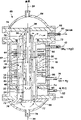
FIG. 1 is a cross-sectional view illustrating a first method of internally generating heat to sustain an endothermic reaction.
FIG. 2 is a cross-sectional illustration of an apparatus for delivering fuel to a preferred combustion zone.
Figures 3-5 are cross-sectional illustrations of an alternative method of internally generating heat to sustain an endothermic reaction.
Fig. 6-8 are designs of reactors illustrating the effectiveness of the process according to the invention in producing synthesis gas.
FIG. 9 is an azimuth view illustrating a number of heat-generating burner tubes and heat-requiring reformer tubes for use in the reactor of the present invention.
FIG. 1 is a cross-sectional illustration ofa first method of providing heat to an endothermic reaction according to the present invention. The endothermic reaction substantially occurs in the reaction channel 10. The preferred endothermic reaction is steam reforming. The process gas 12, which is a gas mixture containing the components required for the steam reforming, flows through the reaction channel 10. For the production of synthesis gas, the process gas 12 comprises methane (or other light alkanes) and steam. The process gas 12 may also contain other reactive components such as carbon dioxide and inert gases.
To enhance the production of the product gas 14, which is preferably a syngas having a hydrogen to carbon monoxide molar ratio greater than about 2.3 to 2.5, at least a portion of the process channels 10 are packed with a catalyst bed 16. The catalyst may consist of beads or, alternatively, the catalyst is attached to a monolithic substrate or contained in a porous layer fixed to the walls of the channel. The catalyst may be uniformly distributed throughout the process channel 10 and have a uniform activity, or may be gradually distributed and have a gradually changing activity, so as to enhance the steam reforming reaction at selected portions of the process channel. The catalyst effective for enhancing the production of synthesis gas by the conversion of methane vapor is selected. One such catalyst is nickel, which may be supported on an alumina substrate. As a practical limitation, the reactor of the present invention includes at least one oxygen selective ion transport membrane element 18. The ion transport membrane element 18 is preferably a mixed conducting metal oxide having an anode on the side facing the reaction channel 10 and a cathode on the opposite side. The air flowing in the air passage 26 provides oxygen that migrates to the anode by ion migration, where partial oxidation occurs.
The heat required to sustain the endothermic reaction is generated in part by the partial oxidation reaction at the anode of the ion transport membrane 18 and in part by the combustion of fuel in the combustion zone 20. To minimize nitrogen contamination of the product gas 14, the combustion zone 20 is isolated from the endothermic reaction by a nitrogen-impermeable barrier. In the embodiment shown in fig. 1, the oxygen selective ion transport membrane element 18 functions as a nitrogen impermeable barrier layer.
The oxygen selective ion transport membrane element 18 may be fabricated in the form of a mixed solid oxide dense wall or a dual phase conductor, or preferably as a mixed solid oxide thin film or a dual phase conductor supported on a porous substrate.
The top film preferably covers only the portion of the reaction channel 10 that is filled with the catalyst 16, and the remaining length of the top film is coated with a metallic or ceramic, gas-impermeable sealing coating such as nickel or ceria.
When formed as a monolithic structure, oxygen-selective ion transport membrane 18 has a nominal thickness of less than 5,000 μm, and preferably a thickness of less than 1,000 μm. When made as a composite, the membrane element is typically less than 100 μm thick and is supported on a porous substrate, preferably made of a low cost ceramic or a nickel-containing metal alloy. Suitable metal alloys include inconel 200 and henna 230. The support structure may also be made of a high strength ceramic material such as alumina, ceria or mixtures thereof.
The intermediate porous layer is generally disposed between the oxygen selective ion transport skin layer membrane and the porous substrate, bridging the chemical and mechanical incompatibility between the substrate and the skin layer. The use of a dense hybrid conductive layer for an intermediate porous transition layer on a porous substrate is disclosed, for example, in U.S. patent 5,240,480 to sorogold et al.
The membrane element has the ability to transport oxygen ions and electrons at a temperature of about 450 c to about 1200 c with a prevailing oxygen partial pressure while maintaining a chemical potential difference on the surfaces on both sides of the ion transport membrane caused by maintaining a positive proportion of oxygen partial pressure on both sides of the ion transport membrane. This defined ratio is preferably achieved by reacting the transferred oxygen with an oxygen-consuming process gas. The conductivity of oxygen ions is generally in the range of 0.01 to 100S/CM, where S ("Siemens") is the reciprocal of ohm (1/omega).
Materials suitable for use as ion transport membranes include mixed conducting perovskites and biphasic metal-metal oxidized mixtures disclosed in U.S. Pat. Nos. 5,702,959 (Mazanik et al), 5,712,220 (Carolan et al) and 5,733,435 (Prisard et al). Which is hereby incorporated by reference in its entirety.
Since the reaction environment on the anode side of the oxygen selective ion transport membrane element generally produces a very low partial pressure of oxygen, some of the chromium-containing perovskites listed in the cited patents may be preferred materials because they tend to be stable in environments with low partial pressures of oxygen. Chromium-containing perovskites generally do not decompose at very low oxygen partial pressures.
A thin layer of porous catalyst, possibly made of the same perovskite material, may optionally be added to one or both sides of the oxygen transport membrane element to enhance surface exchange of oxygen and chemical reaction on the surface. Alternatively, the surface layer of the oxygen selective ion transport membrane element may incorporate, for example, cobalt to enhance the exchange kinetics of the surface. The oxygen selective ion transfer membrane element 18 has a cathode side 22 and an anode side 24. Oxygen-selective ion transport membrane element 18 can be made in any desired shape, such as a tube or plate.
The cathode side 22 contacts the air channel 26. The oxygen-containing gas 28 contacts the cathode side 22 as it flows through the air channel 26. The partial pressure of oxygen in the air channels 26 and the reaction channels 10 is effective to cause a portion of the oxygen contained in the air 28 to migrate 30 from the cathode side 22 to the anode side 24. The oxygen partial pressure on the cathode side 22 is preferably at least 1,000 times greater than the oxygen partial pressure on the anode side 24. More preferably, the oxygen partial pressure difference is about 1010-. For example, the oxygen partial pressure on the cathode side may be about 0.1-10atm and on the anode side about 10-14 atm.
The oxygen-containing gas 28 is typically air and contains about 21% by volume of oxygen at sea level. When the oxygen-containing gas contacts the oxygen selective ion transport membrane element 18 at an effective temperature and oxygen partial pressure, a portion of the oxygen, i.e., the permeate portion, is transported through the oxygen selective ion transport membrane element, while a second portion of the oxygen containedin the air reacts with the fuel 32. The residual gas stream, i.e., the retentate gas, contains primarily nitrogen and some residual oxygen and is discharged as oxygen-depleted gas 34. Such oxygen-depleted gases typically contain less than 6% by volume of oxygen, but are effective in supporting combustion. And therefore does not need to provide a separate oxygen source to support combustion in the combustion zone 20.
The fuel 32 is preferably injected uniformly along the length of the air passages 26 without mixing the fuel 32 with the air 28 to risk early and uneven combustion, or alternatively to generate the heat required for local energy balance in a predetermined manner. Referring to fig. 2, the fuel pipe 36 is made of a high temperature material, such as stainless steel or ceramic, sufficient to withstand the combustion temperature, and is inserted into the air passage 26. The first end 38 of the fuel tube 36 is generally open, while the opposite second end 40 is generally closed. A plurality of apertures 42 are provided in the fuel tube. Fuel 32 enters at first end 38, flows through fuel tube 36, and exits through orifices 42.
The spacing of the apertures 42 is uniform along the length of the fuel tube 36. Preferably, the perforations are arranged in a predetermined manner to generate heat which is highly desirable for local energy balance. As shown in fig. 2, the energy is generally much less at the feed end of the process gas 12 in the reaction channel 10.
A typical syngas production plant utilizing PSA tail gas as fuel 32 and a mixture of methane and steam as process gas will produce sufficient energy to produce H2Syngas with a molar ratio of CO of about 2.7.
FIG. 3 is a schematic diagram illustrating a process for producing H2Another process variant for synthesis gas with a molar ratio/CO of at least 3. The energy to support the reforming reactionis provided by the combustion of the fuel 32 in the combustion channel 44 with oxygen supplied by ion transport through the ion transport membrane 24And (4) burning. The combustion passage 44 is disposed between the reaction passage 10 and the air passage 26. In this embodiment, the nitrogen-impermeable barrier 46 between the combustion channels and the conversion channels is made of a thermally conductive, gas-impermeable material, such as a metallic or ceramic tube or plate.
Oxygen-selective ion transport membrane element 18 is configured with anode side 24 forming the walls of combustion channels 44 and cathode side 22 forming the walls of air channels 26. The oxygen-containing gas 28 is typically air which contacts the cathode side 22 as it flows through the air channels 26, so a portion of the oxygen contained in the air 28 migrates 30 through the oxygen-selective ion transport membrane elements 18 to support combustion in the combustion zone 20 within the combustion channels 44.
The fuel 32 may be a low calorific value fuel. Unlike in the embodiment shown in fig. 1, nitrogen is not included in the combustion environment because only oxygen migrates 30 through the oxygen selective ionic membrane element. Thus, the combustion products 48 discharged from the combustion passage 44 are substantially free of NOxA compound is provided.
The advantage of using an ion transport combustion membrane is that the reaction is distributed over the length of the channel by local oxygen transport, independent of the local fuel/oxygen ratio inside the combustion channel. Therefore, the wall temperature can be easily controlled within a narrow range. The temperature of the oxygen selective ion transport membrane elements is controlled within the operating range of the selected ion transport material, typically 700 c to 1100 c, preferably 800 c to 1000 c, by controlling the mass flowof air 28 and fuel 32, local oxygen flux, local reaction kinetics in the channels 10 controlled by catalyst activity and fluid composition, and suitable heat transfer from the membrane surface to the conversion channels controlled by radiation and convection. The heat capacity of the retentate stream may act as a buffer to limit local temperature excursions. Distributing the injected fuel using the method of fig. 2 may provide other control methods.
Fig. 4 illustrates another method according to the invention. The air passage 26 is disposed between the combustion passage 44 and the reaction passage 10. The first oxygen-selective ion transport membrane element 18 separates the air channels 26 from the combustion channels 44 with its cathode side 22 adjacent the air channels 26 and its anode side 24 adjacent the combustion channels 44.
A second oxygen selective ion transport membrane element 50 separates the combustion channel 44 from the reaction channel 10, with a second cathode side 52 adjacent the combustion channel 44 and a second anode side 54 adjacent the reaction channel 10.
The first permeate portion of the oxygen contained in the oxygen-containing gas 28 migrates 30 to the combustion channel 44 to support the combustion zone 20 and provide oxygen. A second permeate portion of oxygen migrates 30' through the second oxygen selective ion transport membrane element 50 to support the partial oxidation reaction in the reaction channels. The heat required for the endothermic reforming reaction is provided in part by the partial oxidation reaction and in part by the combustion of fuel in the combustion channels 44. H in the product gas 14 is controlled by making the mass flow of the fuel 32 proportional to the light alkane mass flow of the process gas 122Molar ratio of/CO. The ratio of fuel to natural gas is high, which is beneficial to increasing H2The molar ratio of/CO, since such a configuration weakens the partial oxidation reaction in the reaction channel and promotes the conversion.
In this configuration, it is also possible to utilize an impermeable separator layer in place of the second ion transport membrane 50, thereby limiting the reaction within the process channel 10 to steam reforming.
In the embodiment of the invention shown in FIG. 5, first oxygen-selective ion transport membrane element 18 separates air passageway 26 from combustion passageway 44 such that combustion products 48 are substantially free of NOxIn (1).
In this embodiment, the combustion channel 44 is separated from the reaction channel 10 by a second oxygen selective ion transport membrane element 50. A second oxygen selective ion transport membrane element 50 has a second cathode side 52 adjacent the combustion channels 44 and a second anode side 54 adjacent the reaction channels 10.
Oxygen contained in the oxygen-containing gas 28 is transferred 30 through the first oxygen-selective ion transfer membrane element to support combustion in the combustion zone 20. The amount of oxygen transferred exceeds the amount required for combustion and thus an oxygen partial pressure is established between the oxygen in the air channel 26 and the reaction channel 10, and if the oxygen partial pressure in the combustion channel 44 is maintained at an intermediate level between the oxygen partial pressure in the air channel 26 and the oxygen partial pressure in the reaction channel 10, the excess oxygen contained in the combustion channel 44 will be transferred 30' to the reaction channel 10 by the second oxygen selective ion transfer membrane element.
The fuel 32 is less than stoichiometrically required (fuel starved) and is distributed along the length of the combustion channel 44 to facilitate uniform oxygen partial pressure throughout the combustion channel. By controlling the mass flow rates of the oxygen-containing gas 28, the fuel 32 and the process gas 12, the desired oxygen partial pressure distribution is achieved. In this embodiment, the heat required for the endothermic reforming reaction is provided in part by the partial oxidation reaction in the reaction channels and in part by the combustion of fuel in the combustion channels 44.
While the above process scheme illustrates the use of steam for reforming, it will be appreciated that carbon dioxide may be substituted for some or all of the steam in any of the above embodiments.
Figure 6 illustrates, in cross-section, a reactor 60 particularly suitable for the process flow shown in figure 4. The reactor 60 has a hollow shell 62 defining a reactor space. The fuel tube 36 has a first end 38 and an opposite second end 40, with the first tubular oxygen selective ion transport membrane element 18 defining at least a portion of the fuel tube 36. The first oxygen selective ion transport membrane element 18 has an anode side 24 adjacent to a fuel tube 36 and a cathode side 22 on its back side.
A second ion transfer member 50 surrounds the ion transfer member 18 and defines an annular space 26 between the cathode sides 22, 52. Outside the second anode side 54 is the conversion enhancement catalyst 16, which is filled within the length of the intermediate reaction zone. The preheating zone extends from the process gas inlet 12 to the reaction zone and the heat recovery or cooling zone extends from the bottom of the reaction zone to the product outlet 14. The addition of the preheating and cooling zones to the reactor lowers the tube sheet temperature, allows the use of common engineering materials for the tube sheets, such as carbon steel and stainless steel, and facilitates the joining and sealing of the tubes to the tube sheets.
A source of oxygen-containing gas 28, such as air, provides a flow of air along the cathode sides 22 and 52. The reactor bottom cover 68, in combination with the second tube sheet 70, defines a manifold chamber connecting the source of oxygen-containing gas 28 with the air passages 26, the air passages 26 being bounded by the cathodes 22 and 52 of the first oxygen-selective ion transfer membrane element 18 and the second oxygen-selective ion transfer membrane 50, respectively.
The process gas 12 is fed into the reactor 60 on the shell side, or outside of the second oxygen selective ion transport membrane element 50. The process gas 12 is preheated in counter-current flow with hot oxygen-depleted air in a preheating zone and then enters a reaction zone where they undergo partial oxidation reactions with oxygen migrating 30' from the air passages 26 through a second ion transport membrane 50, which undergo conversion reactions with each other to produce a gas having the desired H content2Syngas in a/CO ratio. The resulting product is cooled counter-currently to the incoming air and leaves the reactor as product gas 14.
The heat for the endothermic steam reforming reaction is provided in part by the exothermic partial oxidation reaction and in part by the reaction in the combustion tunnel 44 of the fuel added through the process gas 12 and fuel feed 38 with the oxygen that is ionically transported through the ion transport membrane 50. The heat released by the combustion of the fuel in the combustion channels 44 is transferred into the reaction channels 10 by radiation and convection. An arrangement of concentric tubes is advantageous for radiative heat transfer. High convective heat transfer coefficients can be achieved with a small width of the annular space and/or high gas velocities.
Since the ion transfer tube 50 is impermeable to nitrogen, the combination of the third tube sheet 72, the second tube sheet 70 and the bottom cover 73 forms a nitrogen-impermeable barrier. Nitrogen in the air is prevented from entering the combustion passage 44 and the generation of nitrogen oxides is minimized. Since the combustion passage 44 and the reaction passage 10 are independent of each other, it is possible to use fuel having a low combustion value in the combustion passage 44.
The composition of the product gas 14 is controlled by controlling the composition and mass flow of the process gas 12 and the mass flow and concentration of the fuel 32. To promote complete combustion, it is preferable to maintain the fuel/oxygen ratio within the combustion passage 44 at a lower limit. As previously mentioned, the second end 40 of the fuel tube 36 may optionally be sealed off and fuel may be introduced through a plurality of perforations in the wall of the fuel tube to provide greater control of the combustion zone 20.
To supply oxygen to the partial oxidation and combustion reactions, air is fed to the air channels 26 through fittings 75 and apertures 77. The combustion products of the combustion channel 44 and the oxygen-depleted residual gas in the air channel 26 are discharged into the common space 29, from which they leave the reactor through the connection 81.
In order to make the change in the lengths of the fuel pipe 36, the first and second oxygen-selective ion transport membrane element pipes 18 and 50 caused by the change in temperature and composition unrestricted, a combination of fixed seals and sliding seals is used. The use of fixed seals and sliding seals in shell reactors is described in more detail in patent application 09/089,372. The fuel tubes 36 are restrained by fixedly attaching the first end 38 to a first tube sheet 66. The opposite second end 40 remains free to compensate for axial dimensional changes.
The first end 76 of the first oxygen selective ion transport membrane element 18 is fixedly attached to the second tubesheet 70 and the second end 78 remains free to compensate for axial dimensional changes.
The second ion mobility membrane tube 50 is fixedly secured to the bottom cover 73 and the sliding seals 80 on the third tube sheet 72 and the fourth tube sheet 74 slidably support the second oxygen selective ion mobility membrane element 50 against axial dimensional changes. To reduce the difficulty of servicing the sliding seal 80 and to improve safety, a buffer gas 82, such as steam, may be added between the sliding seal and the fourth tube sheet 74. Only the bottom sealed buffer gas arrangement is illustrated. The same buffer gas unit can be added by adding a tube sheet and shell fitting, sliding seal on top if desired. The buffer gas is introduced at a pressure slightly greater than the process gas 12 or the product gas 14 so that if a leak occurs in the sliding seal 80, steam, components of the steam reforming reaction, will flow into the space of the reactor. As a result, the quality requirements for the sliding seal can be substantially relaxed and leakage of the reaction gas into the oxygen-containing space is avoided.
The process side gases, in the preheating and cooling zones and optionally also in the reaction zone, are guided by transverse baffles 84 through the reactor in a cross-counterflow manner to achieve high heat transfer coefficients, which compensate for the non-uniform flow distribution and non-uniform reaction kinetics if transverse baffles are used in the reaction zone.
If necessary, producing H2The second ion transport membrane tube 50 may optionally be replaced by an impermeable separator tube made of metal or ceramic. In this embodiment, all of the heat required for the reforming reaction is provided by the combustion of the fuel.
The air channels 26 may act as a thermal insulator between the combustion zone 20 and the reaction channel 10. To counteract this effect by achieving high air velocities and high convective heat transfer coefficients, the width of the air channels 26 should be small, preferably below 5mm, more preferably 1-3 mm. This is particularly important in a simple reformer embodiment, where more heat must be transferred from the combustion zone to the reforming reaction. Alternatively, the combustion and air passages may be interchanged such that the combustion passage is located adjacent the reforming passage. This arrangement improves heat transfer in the reaction zone but deteriorates heat transfer in the preheating and cooling zones.
Fig. 7 illustrates, in cross-section, a reactor 90 in which conversion (reaction) channels 10 having catalyst 16 are disposed within a first tubular oxygen-selective ion transport membrane element 18. The first oxygen selective ion transport membrane 18, together with the first and second tube sheets 66, 70, form a nitrogen-impermeable barrier layer for the reaction zone. A second ion transfer membrane tube 50 surrounds the ion transfer membrane tube 18 and defines an annular space bounded by the cathode sides 22, 52 of the two ion transfer membranes 18, 50 and the air passage 26. The combustion channels 44 are disposed on the shell side and outside of the second oxygen selective ion transport membrane element 50 and may include baffles 86 to enhance heat transfer and to compensate for thermal effects of flow maldistribution and non-uniformity. As disclosed above, the reactor comprises a reaction zone, a preheating zone and a cooling zone.
The oxygen-containing gas 28 is typically air, whichis fed into the air channel 26. The first permeated portion of oxygen contained within the air 28 migrates 30 to the reaction channel 10 for partial oxidation reactions. The second portion migrates through oxygen 30' to the combustion channel 44. Fuel 32 is also introduced into the combustion channel 44 and reacts with the permeated oxygen in the combustion zone 20 to generate additional heat for the endothermic reaction occurring within the reaction channel 10.
First oxygen-selective ion transport membrane element 18 is fixedly attached at one end to, for example, a second tube sheet 70, which is slidably attached at the opposite end to first tube sheet 66, so that axial expansion due to temperature and composition changes is not limited. The second oxygen selective ion transport membrane element 50 is fixedly attached at one end to, for example, a third tube sheet 72, and is unconstrained at the opposite end so that axial expansion due to changes in axial length resulting from changes in temperature and composition is unconstrained.
As with the previous embodiment, a segmented steam cushion sliding seal may be employed.
If the preferred reactor 90 design is a simple reformer, the first oxygen selective ion transport membrane element 18 can be replaced with a metal or ceramic tube that does not transport oxygen ions.
Fig. 8 shows a reactor 100 in which a reaction channel 10 and a combustion channel 44 are present, each in a separate tube in the enclosed space of the reactor 100. Combustion is supported by fuel 32, and fuel 32 is channeled to fuel tubes 36 by a plenum defined by, for example, a reactor bottom cover 68 and a first tube sheet 66. Fuel 32 is delivered to combustion passage 44 through a plurality of orifices 42 or, alternatively, through the open second end of the fuel tube.
The fuel tube 36 defines one surface of a combustion passage 44. The opposite surface thereof is defined by the anode side 24 of the first oxygen selective ion transport membrane element 18. The oxygen containing gas 28 is typically air that flows along the cathode side 22 of the oxygen selective ion transport membrane element on the shell side. A portion of the oxygen contained migrates through the oxygen selective ion transport membrane 30 and this portion permeates the oxygen to combine with the fuel 32 in the combustion zone 20 to generate heat to support steam reforming in the process channels 10.
The conversion reaction, which takes place by feeding the process gas 12 into the catalyst-filled reaction channel 10 formed by the annular space between the product discharge tube 81 and the ion transfer tube 50, is separated from the combustion reaction, wherein the process gas is converted in the presence of the catalyst 16 into a product gas 14, which is typically syngas. The nitrogen-impermeable barrier layer separates the reaction channel 10 from the oxygen-containing gas 28 flowing in the enclosed space of the reactor 100. If a partial oxidation reaction is to be supported in the process channel 10, the nitrogen-impermeable separator layer forms a second oxygen-selective ion transport membrane element 50 having a second cathode side in contact with the flowing oxygen-containing gas 28 to cause a portion 30' of the oxygen contained in the oxygen-containing gas 28 to migrate to the second anode side 54. If a separate steam reforming is required, the nitrogen-impermeable barrier layer is made of a metal or ceramic that does not migrate oxygen ions.
Air passes through the shell side in a cross-counterflow manner. The reactor 100 may include cross flow baffles 84 to direct flow, create high velocity, enhance heat transfer, and compensate for flow maldistribution and non-uniform reaction between individual tubes. The heat of the fuel combustion reaction is transferred to the reaction channels by radiative and convective heat transfer.
The first oxygen selective ion transport membrane 18 is fixedly secured at one end to the first tube sheet 66 and the opposite second end of the oxygen selective ion transport membrane element 18 is free to move. Likewise, a second oxygen selective ion transport membrane element 50 is fixedly secured at a first end to a second tube sheet 70, the opposite second end of which is free to move. The reactor is designed such that the variation in axial dimension is not limited and therefore does not require any sliding seals.
The seal between the first tube sheet 66 and the first oxygen-selective ion transport membrane element 18 must be resistant to only small pressure differentials and is readily fabricated by conventional methods such as metal brazing between a metal tube sheet and a metallized tube end. The seal between the second tube sheet 70 and the second oxygen-selective ion transport membrane element 50 must withstand much higher pressure differentials. While conventional seals are sufficient, it is within the scope of the invention to perform the staged sealing by adding a buffer gas between the process gas 12 inlet 102 and the seal. As a result, it is the buffer gas, e.g. steam, that leaks into the hollow housing around the seal, rather than the alkane.
Although fig. 8 shows only a pair of tubes, a typical reactor will contain many tubes that are spaced and loosely supported by laterally spaced baffles that are less spaced to provide adequate heat transfer. Fig. 9 schematically illustrates a portion of a representative tube bundle in which rows of tubes containing reaction channels 10 alternate with rows of tubes containing combustion channels 44. Of course any other suitable tube configuration is also suitable for the reactor of the present invention.
Claims (10)
1. A method of providing heat to an endothermic reaction within a reaction channel, the method comprising the steps of:
isolating said endothermic reaction from the combustion zone with a nitrogen impermeable barrier;
flowing an oxygen-containing gas through air channels along a cathode side of an oxygen-selective ion transport membrane element at a temperature and oxygen partial pressure effective to separate oxygen, to separate oxygen contained in said oxygen-containing gas into a permeate fraction that migrates through said oxygen-selective ion transport membrane element to an anode side and a retentate fraction that remains on said cathode side;
combusting fuel with at least one of said permeate fraction and said retentate fraction in said combustion zone, thereby generating heat of combustion; and
transferring said combustion heat to said endothermic reaction.
2. The method of claim 1 wherein saidreaction channels are separated from said air channels by said oxygen selective ion transport membrane element having said cathode side adjacent to said air channels and said anode side adjacent to said reaction channels.
3. The method of claim 2 including flowing a process gas through said reaction channel and reacting said permeate fraction exothermically with said process gas component in said reaction channel.
4. The process of claim 3 wherein a second oxygen-selective ion transfer membrane element separates said air channels from combustion channels, said second oxygen-selective ion transfer membrane being effective to separate oxygen contained in said oxygen-containing gas into a second permeate portion that is transferred through said second oxygen-selective ion transfer membrane to a second anode side adjacent said combustion channels and a second retentate portion that is retained on said second cathode side.
5. The method of claim 4 including flowing a process gas through said reaction channel and causing said permeate fraction to react exothermically with said process gas component in said reaction channel while causing said fuel to react exothermically with said second permeate fraction in said combustion channel.
6. The method of claim 1 wherein said air channels are separated from combustion channels by said oxygen selective ion transport membrane element having said cathode side adjacent said air channels and said anode side adjacent said reaction channels.
7. A reactor, comprising:
a hollow shell defining a space of the reactor;
a fuel tube extending into said reactor space, said fuel tube having first and second opposite ends;
a first tubular oxygen selective ion transport membrane element defining at least a portion of said fuel tubes, said first oxygen selective ion transport membrane element having a first anode side adjacent said fuel tubes and a first cathode side on a back side thereof;
a nitrogen-impermeable separator tube defining at least a portion of said first tubular oxygen-selective ion transport membrane element thereby defining an annular space between an inner surface of said nitrogen-impermeable separator tube and an outer surface of said first tubular oxygen-selective ion transport membrane element;
a conversion enhancing catalyst disposed outside the nitrogen-impermeable separator tube; a fuel source is connected to the first end of the fuel tube;
a source of oxygen-containing gas opening into said annular space; and
process gas, which is passed to said reactor space.
8. The reactor of claim 7, wherein the width of the annular space is less than 5 mm.
9. A reactor, comprising:
a hollow shell defining a space of the reactor;
a tubular oxygen selective ion transfer membrane element having a first end fixedly attached to the first tubesheet and a second end open to the reactor space, and having a cathode side on an interior surface thereof and an anode on an exterior surface thereof adjacent to the hollow shell;
a nitrogen impermeable tube concentrically disposed within said tubular oxygen selective ion transport membrane element adjacent said cathode side, said nitrogen impermeable tube having a first end fixedly secured to a second tubesheet and a second end slidably secured to a third tubesheet, whereby an outer surface of said nitrogen impermeable tube and an inner surface of said tubular oxygen selective ion transport membrane define an annular space;
a conversion enhancement catalyst disposed within at least a portion of said nitrogen-impermeable barrier tube;
a fuel source in communication with said hollow housing;
a source of oxygen-containing gas in communication with the first end of the annular space; and
and the gas source of the process gas is communicated with the nitrogen-impermeable isolating pipe.
10. A reactor, comprising:
a hollow shell defining a space of the reactor;
a process gas tube fixedly secured to a first tube sheet extending into the hollow shell;
a nitrogen-impermeable tube defining at least a portion of the length of said process gas tube, one end of which is closed and the other end of which is fixedly secured to a second tube sheet;
a conversion catalyst disposed in at least a portion of an annular space formed between the nitrogen-impermeable separator tube and the process gas tube;
a first tubular oxygen selective ion transport membrane element having a first end which is open and a second end which is closed, the first end being fixedly secured to a third tubesheet located opposite the second tubesheet, the membrane element having an inner anode and an outer cathode facing the housing;
a fuel gas tube extending concentrically into at least a portion of the length of said ion transport membrane, at least a portionof the annular space formed between the outer wall of said fuel gas tube and the inner wall of said ion transport membrane tube forming a combustion space;
the shell joint is connected with a gas source containing oxygen;
a housing fitting for exhausting exhaust gas proximate to the open first end of the ion transfer tube;
the fuel pipe joint is connected with a fuel source; and
and the process gas pipe joint is connected with a gas source of process gas.
Applications Claiming Priority (2)
| Application Number | Priority Date | Filing Date | Title |
|---|---|---|---|
| US09/143,974 US6296686B1 (en) | 1998-06-03 | 1998-08-31 | Ceramic membrane for endothermic reactions |
| US09/143974 | 1998-08-31 |
Publications (1)
| Publication Number | Publication Date |
|---|---|
| CN1246384A true CN1246384A (en) | 2000-03-08 |
Family
ID=22506516
Family Applications (1)
| Application Number | Title | Priority Date | Filing Date |
|---|---|---|---|
| CN99118184A Pending CN1246384A (en) | 1998-08-31 | 1999-08-30 | Ceramic membrane for endothermic reaction |
Country Status (11)
| Country | Link |
|---|---|
| US (1) | US6296686B1 (en) |
| EP (1) | EP0984500A3 (en) |
| JP (1) | JP2000109302A (en) |
| KR (1) | KR20000017367A (en) |
| CN (1) | CN1246384A (en) |
| AU (1) | AU4484799A (en) |
| BR (1) | BR9903966A (en) |
| CA (1) | CA2281187A1 (en) |
| ID (1) | ID23738A (en) |
| NO (1) | NO994196L (en) |
| ZA (1) | ZA995566B (en) |
Cited By (4)
| Publication number | Priority date | Publication date | Assignee | Title |
|---|---|---|---|---|
| CN103648972A (en) * | 2011-07-08 | 2014-03-19 | 普莱克斯技术有限公司 | Method and apparatus for producing synthesis gas |
| CN103920439A (en) * | 2002-08-15 | 2014-07-16 | 维罗西股份有限公司 | Integrated combustion reactors and methods of conducting simultaneous endothermic and exothermic reactions |
| CN107635951A (en) * | 2015-05-01 | 2018-01-26 | 维洛西斯技术有限公司 | For operating the method for integrating gas to liquid plant |
| US11447415B2 (en) | 2012-05-31 | 2022-09-20 | Corning Incorporated | Zircon compatible, ion exchangeable glass with high damage resistance |
Families Citing this family (70)
| Publication number | Priority date | Publication date | Assignee | Title |
|---|---|---|---|---|
| EP1188713A3 (en) | 2000-09-18 | 2003-06-25 | Haldor Topsoe A/S | Production of hydrogen and carbon monoxide containing synthesis gas by partial oxidation |
| US6514314B2 (en) * | 2000-12-04 | 2003-02-04 | Praxair Technology, Inc. | Ceramic membrane structure and oxygen separation method |
| US6394043B1 (en) | 2000-12-19 | 2002-05-28 | Praxair Technology, Inc. | Oxygen separation and combustion apparatus and method |
| US6562104B2 (en) * | 2000-12-19 | 2003-05-13 | Praxair Technology, Inc. | Method and system for combusting a fuel |
| GB0106478D0 (en) * | 2001-03-16 | 2001-05-02 | Univ Robert Gordon | Apparatus and method |
| US20040060238A1 (en) * | 2002-08-02 | 2004-04-01 | Retallick William B. | Autothermal catalytic steam reformer |
| US9192929B2 (en) | 2002-08-15 | 2015-11-24 | Velocys, Inc. | Integrated combustion reactor and methods of conducting simultaneous endothermic and exothermic reactions |
| JP4850696B2 (en) * | 2003-02-28 | 2012-01-11 | エクソンモービル リサーチ アンド エンジニアリング カンパニー | Hydrogen production using pressure swing reforming |
| US7053128B2 (en) * | 2003-02-28 | 2006-05-30 | Exxonmobil Research And Engineering Company | Hydrocarbon synthesis process using pressure swing reforming |
| WO2005073126A1 (en) | 2004-01-30 | 2005-08-11 | Idemitsu Kosan Co., Ltd. | Reformer |
| CN101163917B (en) * | 2005-03-10 | 2010-05-19 | 国际壳牌研究有限公司 | Multi-tube heat transfer system for the combustion of a fuel and heating of a process fluid and the use thereof |
| KR101278487B1 (en) * | 2005-03-10 | 2013-07-02 | 쉘 인터내셔날 리써취 마트샤피지 비.브이. | Method of starting up a direct heating system for the flameless combustion of fuel and direct heating of a process fluid |
| CA2601359A1 (en) * | 2005-03-10 | 2006-09-21 | Shell Internationale Research Maatschappij B.V. | A heat transfer system for the combustion of a fuel and heating of a process fluid and a process that uses same |
| US7955423B2 (en) * | 2005-03-21 | 2011-06-07 | Air Products And Chemicals, Inc. | Solid-state membrane module |
| NO20051895D0 (en) * | 2005-04-19 | 2005-04-19 | Statoil Asa | Process for the production of electrical energy and CO2 from a hydrocarbon feedstock |
| NO328777B1 (en) * | 2005-07-01 | 2010-05-10 | Norsk Hydro As | Method and apparatus for mixing and reacting two or more fluids and transferring heat therebetween. |
| KR100899885B1 (en) * | 2006-11-21 | 2009-05-29 | 한국에너지기술연구원 | Method of preparing conductive carbon dioxide membranes and method of separating carbon dioxide |
| US20080260631A1 (en) * | 2007-04-18 | 2008-10-23 | H2Gen Innovations, Inc. | Hydrogen production process |
| KR20100061445A (en) * | 2007-07-20 | 2010-06-07 | 셀 인터나쵸나아레 레사아치 마아츠샤피 비이부이 | A flameless combustion heater |
| AR067577A1 (en) * | 2007-07-20 | 2009-10-14 | Shell Int Research | A NON-FLAMMABLE COMBUSTION HEATER AND METHOD FOR PROVIDING HEAT TO A PROCESS CONDUCT |
| US20090252995A1 (en) * | 2008-04-03 | 2009-10-08 | Eickhoff Steven J | Fuel cell with oxygen transport membrane |
| US8293805B2 (en) * | 2008-05-29 | 2012-10-23 | Schlumberger Technology Corporation | Tracking feedstock production with micro scale gas-to-liquid units |
| US8034308B2 (en) * | 2009-06-09 | 2011-10-11 | Honeywell International, Inc. | Multi-stage multi-tube shell-and-tube reactor |
| US8323463B2 (en) * | 2010-01-22 | 2012-12-04 | Praxair Technology, Inc. | Catalyst containing oxygen transport membrane |
| JP5437869B2 (en) * | 2010-03-16 | 2014-03-12 | 日野自動車株式会社 | Vehicle fuel tank |
| EP2402074A1 (en) * | 2010-06-30 | 2012-01-04 | Ammonia Casale S.A. | A process for selective removal of reaction products from a gaseous system |
| US9561476B2 (en) | 2010-12-15 | 2017-02-07 | Praxair Technology, Inc. | Catalyst containing oxygen transport membrane |
| US8623241B2 (en) | 2011-07-08 | 2014-01-07 | Praxair Technology, Inc. | Oxygen transport membrane system and method for transferring heat to catalytic/process reactors |
| US9486735B2 (en) | 2011-12-15 | 2016-11-08 | Praxair Technology, Inc. | Composite oxygen transport membrane |
| EP2791082B1 (en) | 2011-12-15 | 2021-01-20 | Praxair Technology, Inc. | Method of producing composite oxygen transport membrane |
| US9772109B2 (en) | 2012-07-18 | 2017-09-26 | Phillips 66 Company | Process for enabling carbon-capture from conventional steam methane reformer |
| WO2014100376A1 (en) | 2012-12-19 | 2014-06-26 | Praxair Technology, Inc. | Method for sealing an oxygen transport membrane assembly |
| US9453644B2 (en) | 2012-12-28 | 2016-09-27 | Praxair Technology, Inc. | Oxygen transport membrane based advanced power cycle with low pressure synthesis gas slip stream |
| WO2014107707A2 (en) | 2013-01-07 | 2014-07-10 | Praxair Technology, Inc. | High emissivity and high temperature diffusion barrier coatings for an oxygen transport membrane assembly |
| DE102013103426B4 (en) * | 2013-04-05 | 2018-01-04 | Fraunhofer-Gesellschaft zur Förderung der angewandten Forschung e.V. | Process and membrane module for energy-efficient oxygen production in biomass gasification |
| CA2909974C (en) | 2013-04-26 | 2019-03-05 | Praxair Technology, Inc. | Method and system for producing a synthesis gas in an oxygen transport membrane based reforming system |
| US9212113B2 (en) | 2013-04-26 | 2015-12-15 | Praxair Technology, Inc. | Method and system for producing a synthesis gas using an oxygen transport membrane based reforming system with secondary reforming and auxiliary heat source |
| US9115045B2 (en) | 2013-04-26 | 2015-08-25 | Praxair Technology, Inc. | Method and system for producing methanol using an oxygen transport membrane based reforming system |
| US9938145B2 (en) | 2013-04-26 | 2018-04-10 | Praxair Technology, Inc. | Method and system for adjusting synthesis gas module in an oxygen transport membrane based reforming system |
| US9296671B2 (en) | 2013-04-26 | 2016-03-29 | Praxair Technology, Inc. | Method and system for producing methanol using an integrated oxygen transport membrane based reforming system |
| US9365422B2 (en) | 2013-04-26 | 2016-06-14 | Praxair Technology, Inc. | Method and system for producing a synthesis gas in an oxygen transport membrane based reforming system with recycling of the produced synthesis gas |
| US9611144B2 (en) | 2013-04-26 | 2017-04-04 | Praxair Technology, Inc. | Method and system for producing a synthesis gas in an oxygen transport membrane based reforming system that is free of metal dusting corrosion |
| US9023245B2 (en) | 2013-04-26 | 2015-05-05 | Praxair Technology, Inc. | Method and system for producing a synthesis gas using an oxygen transport membrane based reforming system with secondary reforming |
| WO2015034556A1 (en) | 2013-09-05 | 2015-03-12 | Praxair Technology, Inc. | Method and system for producing a synthesis gas using gas using an oxygen transport membrane based reforming system with secondary reforming and auxiliary heat source |
| CA2919959C (en) | 2013-09-05 | 2022-05-03 | Praxair Technology, Inc. | Method and system for producing methanol using an integrated oxygen transport membrane based reforming system |
| MX2016004495A (en) | 2013-10-07 | 2016-06-16 | Praxair Technology Inc | Ceramic oxygen transport membrane array reforming reactor. |
| US9452388B2 (en) | 2013-10-08 | 2016-09-27 | Praxair Technology, Inc. | System and method for air temperature control in an oxygen transport membrane based reactor |
| CN105764842B (en) | 2013-12-02 | 2018-06-05 | 普莱克斯技术有限公司 | Use the method and system of the production hydrogen of the reforming system based on oxygen transport film with two process transform |
| CA2937943A1 (en) | 2014-02-12 | 2015-08-20 | Praxair Technology, Inc. | Oxygen transport membrane reactor based method and system for generating electric power |
| RU2676062C2 (en) | 2014-03-05 | 2018-12-25 | Праксайр Текнолоджи, Инк. | Method and system for producing liquid hydrocarbon product from fischer-tropsch process using synthesis gas produced from oxygen transport membrane based reforming reactor |
| WO2015160609A1 (en) | 2014-04-16 | 2015-10-22 | Praxair Technology, Inc. | Method and system for oxygen transport membrane enhanced integrated gasifier combined cycle (igcc) |
| WO2016057164A1 (en) | 2014-10-07 | 2016-04-14 | Praxair Technology, Inc | Composite oxygen ion transport membrane |
| US10441922B2 (en) | 2015-06-29 | 2019-10-15 | Praxair Technology, Inc. | Dual function composite oxygen transport membrane |
| US10118823B2 (en) | 2015-12-15 | 2018-11-06 | Praxair Technology, Inc. | Method of thermally-stabilizing an oxygen transport membrane-based reforming system |
| US9938146B2 (en) | 2015-12-28 | 2018-04-10 | Praxair Technology, Inc. | High aspect ratio catalytic reactor and catalyst inserts therefor |
| CN108430921A (en) * | 2016-01-05 | 2018-08-21 | 沙特基础工业全球技术公司 | The system and method for generating carbon monoxide by restoring carbon dioxide with elemental sulfur |
| US10202946B2 (en) * | 2016-03-29 | 2019-02-12 | King Fahd University Of Petroleum And Minerals | Power turbine system |
| KR102154420B1 (en) | 2016-04-01 | 2020-09-10 | 프랙스에어 테크놀로지, 인코포레이티드 | Catalyst-containing oxygen transport membrane |
| WO2018169846A1 (en) | 2017-03-16 | 2018-09-20 | Praxair Technology, Inc. | Method and system for producing hydrogen using an oxygen transport membrane based reforming system |
| EP3797085A1 (en) | 2018-05-21 | 2021-03-31 | Praxair Technology, Inc. | Otm syngas panel with gas heated reformer |
| US20230070799A1 (en) | 2020-01-13 | 2023-03-09 | Praxair Technology, Inc. | Oxygen transport membrane reactors for decarbonization |
| US11492255B2 (en) | 2020-04-03 | 2022-11-08 | Saudi Arabian Oil Company | Steam methane reforming with steam regeneration |
| US11322766B2 (en) | 2020-05-28 | 2022-05-03 | Saudi Arabian Oil Company | Direct hydrocarbon metal supported solid oxide fuel cell |
| US11639290B2 (en) | 2020-06-04 | 2023-05-02 | Saudi Arabian Oil Company | Dry reforming of methane with carbon dioxide at elevated pressure |
| US11492254B2 (en) | 2020-06-18 | 2022-11-08 | Saudi Arabian Oil Company | Hydrogen production with membrane reformer |
| US11583824B2 (en) | 2020-06-18 | 2023-02-21 | Saudi Arabian Oil Company | Hydrogen production with membrane reformer |
| US11787759B2 (en) | 2021-08-12 | 2023-10-17 | Saudi Arabian Oil Company | Dimethyl ether production via dry reforming and dimethyl ether synthesis in a vessel |
| US11578016B1 (en) | 2021-08-12 | 2023-02-14 | Saudi Arabian Oil Company | Olefin production via dry reforming and olefin synthesis in a vessel |
| US11718575B2 (en) | 2021-08-12 | 2023-08-08 | Saudi Arabian Oil Company | Methanol production via dry reforming and methanol synthesis in a vessel |
| US11617981B1 (en) | 2022-01-03 | 2023-04-04 | Saudi Arabian Oil Company | Method for capturing CO2 with assisted vapor compression |
Family Cites Families (17)
| Publication number | Priority date | Publication date | Assignee | Title |
|---|---|---|---|---|
| US4791079A (en) | 1986-06-09 | 1988-12-13 | Arco Chemical Company | Ceramic membrane for hydrocarbon conversion |
| US5306411A (en) | 1989-05-25 | 1994-04-26 | The Standard Oil Company | Solid multi-component membranes, electrochemical reactor components, electrochemical reactors and use of membranes, reactor components, and reactor for oxidation reactions |
| US4793904A (en) | 1987-10-05 | 1988-12-27 | The Standard Oil Company | Process for the electrocatalytic conversion of light hydrocarbons to synthesis gas |
| DE3921390A1 (en) | 1989-06-29 | 1991-01-17 | Merck Patent Gmbh | METHOD AND DEVICE FOR PRODUCING PURE OXYGEN |
| US5567398A (en) | 1990-04-03 | 1996-10-22 | The Standard Oil Company | Endothermic reaction apparatus and method |
| AU661877B2 (en) * | 1990-04-03 | 1995-08-10 | Standard Oil Company, The | Endothermic reaction apparatus |
| US5750279A (en) | 1992-02-28 | 1998-05-12 | Air Products And Chemicals, Inc. | Series planar design for solid electrolyte oxygen pump |
| US5356728A (en) | 1993-04-16 | 1994-10-18 | Amoco Corporation | Cross-flow electrochemical reactor cells, cross-flow reactors, and use of cross-flow reactors for oxidation reactions |
| US5468430A (en) * | 1994-05-19 | 1995-11-21 | L'air Liquide S.A. | Process of making multicomponent or asymmetric gas separation membranes |
| US5681373A (en) | 1995-03-13 | 1997-10-28 | Air Products And Chemicals, Inc. | Planar solid-state membrane module |
| US5599383A (en) | 1995-03-13 | 1997-02-04 | Air Products And Chemicals, Inc. | Tubular solid-state membrane module |
| US5820655A (en) * | 1997-04-29 | 1998-10-13 | Praxair Technology, Inc. | Solid Electrolyte ionic conductor reactor design |
| US6077323A (en) * | 1997-06-06 | 2000-06-20 | Air Products And Chemicals, Inc. | Synthesis gas production by ion transport membranes |
| US6048472A (en) * | 1997-12-23 | 2000-04-11 | Air Products And Chemicals, Inc. | Production of synthesis gas by mixed conducting membranes |
| US6153163A (en) * | 1998-06-03 | 2000-11-28 | Praxair Technology, Inc. | Ceramic membrane reformer |
| US6139810A (en) * | 1998-06-03 | 2000-10-31 | Praxair Technology, Inc. | Tube and shell reactor with oxygen selective ion transport ceramic reaction tubes |
| US6010614A (en) * | 1998-06-03 | 2000-01-04 | Praxair Technology, Inc. | Temperature control in a ceramic membrane reactor |
-
1998
- 1998-08-31 US US09/143,974 patent/US6296686B1/en not_active Expired - Lifetime
-
1999
- 1999-07-22 ID IDP990697D patent/ID23738A/en unknown
- 1999-08-18 KR KR1019990034096A patent/KR20000017367A/en not_active Application Discontinuation
- 1999-08-30 ZA ZA9905566A patent/ZA995566B/en unknown
- 1999-08-30 JP JP11242989A patent/JP2000109302A/en not_active Abandoned
- 1999-08-30 CN CN99118184A patent/CN1246384A/en active Pending
- 1999-08-30 CA CA002281187A patent/CA2281187A1/en not_active Abandoned
- 1999-08-30 NO NO994196A patent/NO994196L/en not_active Application Discontinuation
- 1999-08-30 AU AU44847/99A patent/AU4484799A/en not_active Abandoned
- 1999-08-30 EP EP99117067A patent/EP0984500A3/en not_active Withdrawn
- 1999-08-30 BR BR9903966-4A patent/BR9903966A/en not_active Application Discontinuation
Cited By (4)
| Publication number | Priority date | Publication date | Assignee | Title |
|---|---|---|---|---|
| CN103920439A (en) * | 2002-08-15 | 2014-07-16 | 维罗西股份有限公司 | Integrated combustion reactors and methods of conducting simultaneous endothermic and exothermic reactions |
| CN103648972A (en) * | 2011-07-08 | 2014-03-19 | 普莱克斯技术有限公司 | Method and apparatus for producing synthesis gas |
| US11447415B2 (en) | 2012-05-31 | 2022-09-20 | Corning Incorporated | Zircon compatible, ion exchangeable glass with high damage resistance |
| CN107635951A (en) * | 2015-05-01 | 2018-01-26 | 维洛西斯技术有限公司 | For operating the method for integrating gas to liquid plant |
Also Published As
| Publication number | Publication date |
|---|---|
| CA2281187A1 (en) | 2000-02-29 |
| US6296686B1 (en) | 2001-10-02 |
| NO994196D0 (en) | 1999-08-30 |
| AU4484799A (en) | 2000-03-16 |
| NO994196L (en) | 2000-03-01 |
| EP0984500A3 (en) | 2004-07-21 |
| KR20000017367A (en) | 2000-03-25 |
| ZA995566B (en) | 2000-03-27 |
| ID23738A (en) | 2000-05-11 |
| BR9903966A (en) | 2002-02-26 |
| EP0984500A2 (en) | 2000-03-08 |
| JP2000109302A (en) | 2000-04-18 |
Similar Documents
| Publication | Publication Date | Title |
|---|---|---|
| CN1246384A (en) | Ceramic membrane for endothermic reaction | |
| CN1239014A (en) | Syngas reactor with ceramic membrane | |
| RU2182036C2 (en) | METHOD OF SEPARATION OF OXYGEN GAS FLOW INTO GAS FLOW ENRICHED IN OXYGEN AND GAS FLOW DEPLETED IN OXYGEN (Versions) | |
| JP3453303B2 (en) | Design of solid electrolyte ion conductor reactor | |
| CN1564708A (en) | Ion transport membrane apparatus and process | |
| CN1237533A (en) | Ceramic membrane reformer | |
| JPH09503615A (en) | Built-in converter / CPN solid oxide fuel cell stack / module design | |
| US6881394B2 (en) | Steam reformer for methane with internal hydrogen separation and combustion | |
| US7267804B2 (en) | Membrane reactor for gas extraction | |
| JP4043383B2 (en) | Membrane reactor and synthesis gas production method using the same | |
| JP2004051428A (en) | Membrane reaction apparatus | |
| JP3094435B2 (en) | Insulated reformer | |
| JPS5978906A (en) | Steam reforming furnace | |
| MXPA99007978A (en) | Ceramic membrane for endotermi reactions | |
| US20040136883A1 (en) | Membrane reactor for gas extraction | |
| CN1205911A (en) | Integrated solid electrolyte ionic conductor separator-cooler | |
| JP2003277009A (en) | Membrane reactor | |
| JP2005162586A (en) | Apparatus for manufacturing hydrogen | |
| AU2002323080A1 (en) | Ion transport membrane apparatus and process | |
| MXPA98003331A (en) | Design of ionic driver reactor of elctrolito sol | |
| MXPA98003329A (en) | Separator-integrated conductor cooler ionicode electrolito sol |
Legal Events
| Date | Code | Title | Description |
|---|---|---|---|
| C06 | Publication | ||
| PB01 | Publication | ||
| ASS | Succession or assignment of patent right |
Owner name: PLEX TECHNOLOGIES CORP. Free format text: FORMER OWNER: PLACER TECHNOLOGY CO., LTD. Effective date: 20010824 |
|
| C41 | Transfer of patent application or patent right or utility model | ||
| TA01 | Transfer of patent application right |
Effective date of registration: 20010824 Applicant after: Praxair Technology, Inc. Applicant before: Praxair Technology Inc. |
|
| C10 | Entry into substantive examination | ||
| SE01 | Entry into force of request for substantive examination | ||
| C02 | Deemed withdrawal of patent application after publication (patent law 2001) | ||
| WD01 | Invention patent application deemed withdrawn after publication |