CN1244236C - Distance calculating method and imaging pick up device - Google Patents
Distance calculating method and imaging pick up device Download PDFInfo
- Publication number
- CN1244236C CN1244236C CNB028004752A CN02800475A CN1244236C CN 1244236 C CN1244236 C CN 1244236C CN B028004752 A CNB028004752 A CN B028004752A CN 02800475 A CN02800475 A CN 02800475A CN 1244236 C CN1244236 C CN 1244236C
- Authority
- CN
- China
- Prior art keywords
- distance
- value
- optical axis
- utilize
- lens combination
- Prior art date
- Legal status (The legal status is an assumption and is not a legal conclusion. Google has not performed a legal analysis and makes no representation as to the accuracy of the status listed.)
- Expired - Fee Related
Links
- 238000000034 method Methods 0.000 title description 31
- 238000003384 imaging method Methods 0.000 title 1
- 238000004364 calculation method Methods 0.000 claims abstract description 56
- 230000003287 optical effect Effects 0.000 claims abstract description 37
- 238000012545 processing Methods 0.000 claims description 14
- 238000010276 construction Methods 0.000 abstract description 22
- 230000007547 defect Effects 0.000 abstract 1
- 230000002093 peripheral effect Effects 0.000 abstract 1
- 238000012937 correction Methods 0.000 description 29
- 238000006243 chemical reaction Methods 0.000 description 16
- 238000007792 addition Methods 0.000 description 9
- 238000005516 engineering process Methods 0.000 description 5
- 230000000740 bleeding effect Effects 0.000 description 4
- 238000000205 computational method Methods 0.000 description 4
- 230000002950 deficient Effects 0.000 description 4
- 238000010586 diagram Methods 0.000 description 4
- 238000006073 displacement reaction Methods 0.000 description 4
- 230000001915 proofreading effect Effects 0.000 description 4
- 239000004065 semiconductor Substances 0.000 description 4
- 238000007796 conventional method Methods 0.000 description 3
- 238000013459 approach Methods 0.000 description 2
- 239000003086 colorant Substances 0.000 description 2
- 230000006835 compression Effects 0.000 description 2
- 238000007906 compression Methods 0.000 description 2
- 238000012546 transfer Methods 0.000 description 2
- 206010027146 Melanoderma Diseases 0.000 description 1
- 230000015572 biosynthetic process Effects 0.000 description 1
- 230000001419 dependent effect Effects 0.000 description 1
- 238000013461 design Methods 0.000 description 1
- 230000010365 information processing Effects 0.000 description 1
- 238000012986 modification Methods 0.000 description 1
- 230000004048 modification Effects 0.000 description 1
- 230000010287 polarization Effects 0.000 description 1
- 230000003068 static effect Effects 0.000 description 1
- 238000006467 substitution reaction Methods 0.000 description 1
- 230000001360 synchronised effect Effects 0.000 description 1
Images


Classifications
-
- G06T5/80—
-
- H—ELECTRICITY
- H04—ELECTRIC COMMUNICATION TECHNIQUE
- H04N—PICTORIAL COMMUNICATION, e.g. TELEVISION
- H04N1/00—Scanning, transmission or reproduction of documents or the like, e.g. facsimile transmission; Details thereof
- H04N1/40—Picture signal circuits
-
- G—PHYSICS
- G06—COMPUTING; CALCULATING OR COUNTING
- G06T—IMAGE DATA PROCESSING OR GENERATION, IN GENERAL
- G06T7/00—Image analysis
-
- H—ELECTRICITY
- H04—ELECTRIC COMMUNICATION TECHNIQUE
- H04N—PICTORIAL COMMUNICATION, e.g. TELEVISION
- H04N25/00—Circuitry of solid-state image sensors [SSIS]; Control thereof
- H04N25/60—Noise processing, e.g. detecting, correcting, reducing or removing noise
- H04N25/61—Noise processing, e.g. detecting, correcting, reducing or removing noise the noise originating only from the lens unit, e.g. flare, shading, vignetting or "cos4"
Abstract
The present invention relates to a distance calculation method and an image pick-up apparatus that can be favorably used in a digital camera, for example, when calculating a distance between a point corresponding to an optical axis of the lens system on an image pick-up unit and a desired point and using the calculated distance value to correct defects such as shading that occur in formed images due to peripheral light fall-off in the lens system, for example. Accordingly, in the present invention, desired coordinates from terminals 1X, 1Y and coordinates of a center position from terminals 2X, 2Y are supplied to subtractors 3X, 3Y and absolute value circuits 4X, 4Y and distance values x, y on the coordinate axes are obtained. These distance values x, y are supplied to an adder 5 and a subtractor 6, and the subtracted value is supplied to a multiplier 8 via an absolute value circuit 7 and is multiplied by a value b' from a terminal 9. The distance value x is shifted upwards by one bit, the distance value y is subtracted by a subtractor 10, and the result is supplied to an absolute value circuit 11. The distance value y is shifted upwards by one bit, the distance value x is subtracted by a subtractor 12, and the result is supplied to an absolute value circuit 13. These absolute values are added by an adder 14 and the result is multiplied by a multiplier 15 by a value c' from a terminal 16. The values found by the adder 5 and the multipliers 8, 15 are added by adders 17, 18 and a calculated value d' for the pseudo distance is obtained from a terminal 19. By doing so, distances can be well calculated by a simple hardware construction.
Description
Technical field
The present invention relates to a kind of distance calculating method and image pick up equipment, when for example being used for digital camera, this distance calculating method and image pick up equipment can be used to calculate on the image pickup units and the distance between corresponding point of the optical axis of lens combination and the required point effectively, then, when the compensation because, for example, the ambient light decay of lens combination, during the defective of shade that in output image, forms and so on, use the calculated distance value, relate in particular to and to utilize the hardware simplicity structure to calculate distance effectively and can utilize the distance calculating method and the image pick up equipment of calculated distance value offset lens shade etc.
Background technology
In the image picking system that generally contains lens combination and image pickup units, exist because, for example, the decay of ambient light that lens combination causes appears at the risk of the defective of shade in the photographic images that picks up or blackspot and so on.The formation of this defective can be passed through, for example, and the design lens combination, so that comprising a plurality of lens is prevented, this lens combination of being made up of a plurality of lens costs an arm and a leg, and causes in many cases, can not use such lens combination in household electrical appliance.
On the other hand, for example, when the situation of utilizing the semiconductor image pick device as electrical equipment, during according to X-Y coordinate system output signal, image can obtain proofreading and correct by output signal being carried out digital processing.For example, in the field of scanner etc., various technology have been proposed, the lens shade such as distortion, ambient light decay and bleeding that is used for occurring when digital compensation carries out image pickup with the cheap lens system (referring to date of publication present patent application 11-355511 number, 2000-41183 number etc.).
But these conventional arts are only to be applied to the field of scanner and similar devices, and are for example the same with the situation of digital camera in this field, allow compensation deals cost reasonable time and do not need to carry out real-Time Compensation.On the other hand, for example, date of publication present patent application 2000-41179 has proposed the technology of digital compensation lens shade etc. in digital camera.
In more detail, utilizing lens combination to carry out in the equipment of image pickup, the lens shade such as distortion, ambient light decay and bleeding is considered to and distance dependent apart from the optical axis of lens combination.For this reason, if, can reduce the lens shade according to the picture element signal of this range correction by the image pickup generation, perhaps, can the offset lens shade.Therefore, in order to carry out such compensation, how far be necessary at first to calculate the pixel that will proofread and correct has on earth apart from the optical axis of lens combination.
But, to calculate in the conventional method apart from d of lens axis, the distance between initial point 0 and the correction target pixel is represented with the y on x on the X coordinate and the Y coordinate, utilizes Pythagoras (Pythagoras) principle to obtain apart from being
But,, need very large circuit structure realize calculation element at hardware aspect owing to carry out square calculating and evolution calculating.
Should be noted that, though top calculating can finish with software,, exist such computed in software and spent in problem in the processing that will in digital camera, carry out in real time the too many time.Though proposed to utilize and oversimplified the technology (the date of publication present patent application is 7-95856 number) that hardware calculates, but, such calculating is inaccuracy very, so that in order to proofread and correct the brightness such as the ambient light decay, be necessary the distance that computational accuracy is higher.
In addition, for top hardware based distance calculation, exist when size when image pickup units changes or reading method changes, for example, when at charge transfer device when skipping pixel under the situation of image pickup units, can not correctly obtain apart from the risk of the distance of optical axis.That is to say that when skipping pixel like that shown in Figure 18 A, originally the correction of carrying out like that becomes the correction of carrying out like that shown in Figure 18 C, may utilize mounting hardware correctly to proofread and correct so that no longer include shown in Figure 18 B.
The present invention makes after the problem on considered, attempts to solve the problem of conventional method and equipment existence, and these problems are included in hardware aspect needs very large circuit structure realize calculation element; Oversimplify circuit structure and can not calculate distance accurately; With when reading method changes, for example, when the size of image pickup units changes, perhaps, when skipping pixel, can not correctly obtain distance apart from optical axis.
Summary of the invention
The present invention is calculating with the corresponding point of optical axis and the distance between the required point of lens combination and is utilizing the calculated distance value to proofread and correct on the image pickup units, for example, and owing to the decay defective of shade of causing and so on of the ambient light of lens combination.For this reason, calculated distance value correcting lens shade etc. is calculated and utilized to utilization of the present invention by the formula that polygonal approximation calculates distance.Like this, can utilize the hardware simplicity structure suitably to calculate distance and utilize suitably correcting lens shade etc. of calculated distance value.Relevant therewith, distance calculating method of the present invention and image pick up equipment are disclosed.
Description of drawings
Fig. 1 is a key diagram of having used distance calculating method of the present invention;
Fig. 2 is a key diagram of having used distance calculating method of the present invention;
Fig. 3 has shown the calcspar of the embodiment of the distance calculation device of having used distance calculating method of the present invention;
Fig. 4 has shown the calcspar of another embodiment of the distance calculation device of having used distance calculating method of the present invention;
Fig. 5 has shown the calcspar of another embodiment of the distance calculation device of having used distance calculating method of the present invention;
Fig. 6 has shown the calcspar of another embodiment of the distance calculation device of having used distance calculating method of the present invention;
Fig. 7 has shown the calcspar of another embodiment of the distance calculation device of having used distance calculating method of the present invention;
Fig. 8 is a key diagram of skipping coordinate;
Fig. 9 has shown the calcspar of another embodiment of the distance calculation device of having used distance calculating method of the present invention;
Figure 10 has shown the calcspar of another embodiment of the distance calculation device of having used distance calculating method of the present invention;
Figure 11 has shown the calcspar of another embodiment of the distance calculation device of having used distance calculating method of the present invention;
Figure 12 has shown the calcspar of having used the embodiment of image pick up equipment of the present invention;
Figure 13 has shown the calcspar of having used another embodiment of image pick up equipment of the present invention;
Figure 14 has shown the calcspar of having used another embodiment of image pick up equipment of the present invention;
Figure 15 has shown the calcspar of having used another embodiment of image pick up equipment of the present invention;
Figure 16 has shown the calcspar of having used another embodiment of image pick up equipment of the present invention;
Figure 17 has shown the calcspar of having used another embodiment of image pick up equipment of the present invention; With
Figure 18 is the key diagram of skipping.
Embodiment
The present invention is described with reference to the accompanying drawings.At first, distance calculating method of the present invention is described as, for example, utilize to calculate the distance value x on the X reference axis and the method for the distance value y on the Y reference axis between arbitrary origin 0 and the required point, calculate as shown in Figure 1 arbitrary origin 0 and required point between apart from d.After this, when calculating, as shown in Figure 2, undertaken calculating in the equidistant curve of the concentrically ringed form of initial point 0 with the center by making concentric circles approach positive 16 limit shapes apart from d.
That is to say,, provide as follows apart from the formula of d by approaching 16 limit shapes in such a way:
D=a (x+y)+b|x-y|+c[|2x-y|+|x-2y|] ... [equation 1]
When utilize point (r, 0) apart from d=4, point (r, distance r)
And point (r, distance 2r)
Separate [equation 1], so as to calculate the distance as each summit in the 16 limit shapes apart from the time, it is as follows to provide coefficient value:
Therefore, by these coefficients (a, b, in the c) substitution [equation 1], can for required point (x, y) obtain by positive 16 limit shapes approximate apart from d.In this case, the calculating shown in the equation 1 no longer comprise obtain a number square or the calculating of evolution, therefore can utilize, for example, hardware is easily realized calculation element.
In more detail, Fig. 3 has shown an embodiment of the distance calculation device of having used distance calculating method of the present invention.Should be noted that, in this embodiment, utilize the following equation value of obtaining d '=d/a as distance:
D '=(x+y)+b ' | x-y|+c ' [| 2x-y|+|x-2y|] ... [equation 2] herein,
Therefore, can find, be the multiple of counterfeit distance or pseudo-distance d ' apart from d, and, utilize looking into of this sample value with table, can be ready to form etc. in advance according to counterfeit value apart from d '.
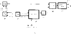
In Fig. 3, the information the location of pixels of relevant required pixel that is to say, the coordinate of the coordinate of the horizontal direction of required Pixel Information (X-axis) and vertical direction (Y-axis) offers end points 1X and 1Y.The information of relevant optical axis center position, that is to say that also the coordinate of the coordinate of horizontal direction (X-axis) and vertical direction (Y-axis) offers end points 2X and 2Y respectively.Also these positional informations are offered subtracter 3X and 3Y respectively, with offer absolute value (ABS) circuit 4X and 4Y subtracting each other the result so that obtain in distance value x on the X reference axis and the distance value y on the Y reference axis for the distance between arbitrary origin 0 and the required point.
The distance value x of ABS circuit 4X and 4Y output and distance value y are offered the adder 5 on first on right side obtaining [equation 2] that provide previously.Also distance value x and distance value y are offered subtracter 6 and offer absolute value (ABS) circuit 7 subtracting each other the result, thereby draw absolute value in second on the right side of [equation 2] that provide previously.This absolute value is offered multiplier 8, in multiplier 8 this value with multiply each other from the value b ' of end points 9 so that draw second on the right side of [equation 2].
Also the distance value x position that moves up.Should be noted that,, therefore, be equivalent to the value position that moves up make this value to double with in the present embodiment value binary representation.In the accompanying drawings, upward displacement is shown as [<<n], and wherein n represents the figure place that moves.The distance value x that has doubled is offered the subtracter 10 that therefrom deducts above-mentioned distance value y.Offer absolute value (ABS) circuit 11 subtracting each other the result, in ABS circuit 11, obtain first absolute value in the 3rd on the right side of above-mentioned [equation 2].
Also above-mentioned distance value x is offered subtracter 12, and the above-mentioned distance value y position that moves up, and also provide it to subtracter 12.From distance value x, deduct the distance value y that has doubled, and offer absolute value (ABS) circuit 13 subtracting each other the result.In ABS circuit 13, obtain second absolute value in the 3rd on the right side of above-mentioned [equation 2].These absolute values are added together by adder 14, offer multiplier 15 then, so that the value c ' of result and end points 16 supplies is multiplied each other, thus the 3rd on the right side that draws [equation 2].
The value that the right side of the value that the right side of above-mentioned [equation 2] obtained by multiplier 8 of adder 17 additions is second and [equation 2] obtained by multiplier 15 is the 3rd, and addition result and adder 5 are obtained first addition in right side of [equation 2] by adder 18.Like this, calculate the value d ' of counterfeit distance according to [equation 2] that provides above, and from this value of end points 19 outputs d '.Should be noted that, value d ' and a can be multiplied each other, draw that the usefulness of looking into that perhaps can utilize prior different value d ' for counterfeit distance to provide is shown apart from d.
Therefore, by means of present embodiment, the equation that utilizes polygonal approximation to calculate distance is used to calculate, so that the computational methods that can utilize simple hardware construction to realize.By utilizing calculated distance value like this, correcting lens shade etc. suitably in the equipment real-time treatment for correcting of needs, such as digital camera.
Like this, the invention solves when realizing the distance calculation device by hardware, traditional distance calculation needs very large circuit structure and can not calculate the problem of distance with simplification hardware accurately.
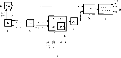
In addition, in the above among the embodiment, multiplier 8 and 15 be used to multiply each other b ' and value c ', but such multiplier does not always have little circuit structure.For this reason, the method for removing multiplier is described in following embodiment.That is to say that Fig. 4 has shown the calcspar of an embodiment of the distance calculation device that uses the method for having removed above-mentioned multiplier.Should be noted that, in the explanation of the calcspar of Fig. 4, give the identical label of the corresponding part of those parts with above-mentioned calcspar shown in Figure 3, and omit being repeated in this description them.
In Fig. 4, the absolute value from absolute value (ABS) circuit 7 is offered adder 20, with the results added of this absolute value with a position [<<1] gained that this absolute value is moved up.Like this, adder 20 has carried out input value be multiply by 3 calculating.Then, addition result is moved down 4 positions, and export it.To offer adder 21 from the absolute value of absolute value circuit 11 outputs and the absolute value of exporting from absolute value circuit 13, and then, addition result be moved down 3 positions, and export it.
Should be noted that,, therefore, move down 4 positions and be equivalent on duty with 1/16 with move down 3 positions and be equivalent on duty with 1/8 with in the present embodiment value binary representation.In addition, in the accompanying drawings, displacement downwards is shown as [>>m], and wherein m represents the figure place that moves.The value addition that adder 17 is obtained adder 20 and 21.The remainder of calcspar is identical with above-mentioned calcspar shown in Figure 3.
By means of current circuit, the input value of adder 20 experience with on duty with 3/16 processing.As top given,
And 3/16 ≈ 0.1875, these two value approximately equals.In addition, the input value of adder 20 also experiences on duty with 1/8 processing.As top given,
And 1/8 ≈ 0.125, these two value approximately equals.
Therefore, in the present embodiment, and need not to use multiplier, only utilize addition and displacement, just can be worth multiplying each other of b ' and value c '.In addition, the value that is used to be worth b ' and c ' is not limited to 3/16 and 1/8.For example, utilize approximation 5/32=0.15625, can be worth multiplying each other of c ' by addition and displacement.In addition, depend on the factor such as employed hardware, also can select other appropriate value.
In addition, among the embodiment, positive 16 limit shapes have been described in the above as approaching concentrically ringed polygonal situation, still, other polygon, for example, positive 8 limit shapes also can be used to approach concentric circles.That is to say, can utilize following formula to obtain the value d ' of counterfeit distance:
D '=(x+y)+k|x-y| ... [equation 3]
In [equation 3], value
Be approximately equal to 0.4142135, still,, can utilize the such circuit structure of all circuit structures as shown in Figure 5 by approximate as 1/2=0.5 this value k.That is to say that Fig. 5 has shown and utilizes an embodiment of distance calculation device who carries out the method for distance calculation by [equation 3] that provide above.Should be noted that, in the explanation of the calcspar of Fig. 5, give the identical label of the corresponding part of those parts with above-mentioned calcspar shown in Figure 3, and omit being repeated in this description them.
In Fig. 5, above-mentioned distance value x and distance value y from absolute value circuit 4X and 4Y offered adder 31, obtain first on the right side of [equation 3] that provide above.Also above-mentioned distance value x and distance value y from absolute value circuit 4X and 4Y offered subtracter 32, and offer absolute value (ABS) circuit 33 subtracting each other the result, thereby draw the absolute value on second on the right side of [equation 3] that provide above.Then, the absolute value of gained is moved down 1 position [>>1], and export it.
Should be noted that therefore the value binary representation with in the present embodiment, moves down 1 position with a value and be equivalent on duty with 1/2.Consequently, the right side of [equation 3] that provides above obtaining in absolute value circuit 33 is second.Then, the value obtained of adder 18 addition adders 31 and absolute value circuit 33.The other parts of calcspar are identical with appropriate section in the calcspar shown in Figure 3.By computing in this manner, can calculate the value d ' of counterfeit distance according to [equation 3] that provide above, and export it from end points 19.
Therefore, by means of present embodiment, the formula that utilizes polygonal approximation to calculate distance is used to calculate, so that the computational methods that can utilize simple hardware construction to realize.By utilizing calculated distance value like this, correcting lens shade etc. suitably in the equipment real-time treatment for correcting of needs, such as digital camera.
Like this, the invention solves when realizing the distance calculation device by hardware, traditional distance calculation needs very large circuit structure and can not calculate the problem of distance with simplification hardware accurately.
But, for top embodiment, when the size of image pickup units changes, perhaps when reading method changes, for example, when at charge transfer device when skipping pixel under the situation of image pickup units, can not correctly obtain distance apart from optical axis.That is to say, as described in background technology, when shown in Figure 18 A, skipping pixel like that, jump owing to skip or claim, originally the correction of carrying out like that shown in Figure 18 B becomes the correction of carrying out like that shown in Figure 18 C, so that can not utilize the calculating of being undertaken by mounting hardware correctly to proofread and correct.
For this reason, describe below having made the situation of such change, correct calculation is apart from the device of the distance of optical axis.That is to say that Fig. 6 to 11 has shown right, for example, skip the situation of scan line in vertical direction, correct calculation is apart from the device of the distance of optical axis.Should be noted that, in the explanation of the calcspar shown in Fig. 6 to 11, give the identical label of the corresponding part of those parts with calcspar shown in Figure 3, and omit being repeated in this description them.
At first, in Fig. 6, the value that the subtracter 3Y of the distance value y of obtaining vertical (Y-axis) direction is obtained offers transducer (conv) 40.According to, for example, skipping along vertical direction under the situation of scan line, from, for example, the information of skipping of end points 41 supplies, transducer 40 conversions are based on the value of skipping.The value of conversion is offered absolute value (ABS) circuit 4Y, and obtain from arbitrary origin 0 to required distance value y on the Y reference axis.
That is to say, provide relevant, for example, the information of the required location of pixels of vertical direction as the counting of number of scanning lines, still, is being carried out under the situation about skipping, and count value will reduce because of the line number of having skipped.Transducer 40 carries out the conversion based on the information of skipping of supplying from end points 41, count value is converted to the count value of situation about not skipping, so that can correctly obtain the distance apart from optical axis.
Should be noted that in fact top conversion is what to be undertaken by the inverse that multiply by skip rate.Therefore, can be configured to above-mentioned circuit structure shown in Figure 6, for example, as shown in Figure 7, have multiplier 42 and the inverse of skip rate offered its end points 43.For example, when shown in the A among above-mentioned Figure 18, skipping like that,, can not recover right value even a value multiply by the inverse of skip rate simply, but as shown in Figure 8, error is ± 1, this does not have big influence to correcting gain, therefore, can not cause what problem.
But, for example, as shown in Figure 9, after multiplier 42, be equipped with adder 44, with according to offering end points 45 and every line being identified into value of line ID signal (1) adding of odd lines or even lines as the device of further proofreading and correct this error.Therefore, for example, as shown in Figure 8, for such as value " 4 " or " 12 " such part after the conversion that is not equal to actual count value " 5 " and " 13 ", can eliminate error in the range correction by adding " 1 ".
In the numerical value conversion in the above, for example, as shown in figure 10, transducer 40 (or multiplier 42) can be positioned at after the absolute value circuit 4Y, and its conversion draws and former identical value.
In the numerical value conversion in the above, for example, as shown in figure 11, when except the line that carries out in vertical direction is skipped, when also skipping pixel in the horizontal direction, the value that the subtracter 3C of the distance value x of obtaining level (X-axis) direction is obtained offers transducer (conv) 46.According to, for example, skip information from the level of end points 47 supplies, transducer 46 conversions are based on the value of skipping.Conversion value is offered absolute value (ABS) circuit 4X, obtain the arbitrary origin 0 that provides from above to the distance value x of required pixel on the X reference axis.
That is to say that relevant, for example, the information of the required location of pixels of horizontal direction offers end points 1X,, still, carrying out under the situation about skipping that count value reduces according to the mode of skipping as the counting of pixel count.Transducer 46 carries out based on the conversion from the information of skipping of end points 47 supply, and count value is converted to the count value that does not have under the situation that pixel skips, so that can correctly obtain the distance apart from optical axis.
Should be noted that, can be applied to any embodiment shown in above-mentioned Fig. 6,7,8 and 9 conversion of also having carried out carrying out when situation that pixel skips is obtained distance value x in level (X-axis) direction.
Therefore, by means of present embodiment, the formula that utilizes polygonal approximation to calculate distance is used to calculate, even so that for the situation of all having carried out in vertical direction and/or horizontal direction skipping, the also computational methods that can utilize simple hardware construction to realize.By utilizing calculated distance value like this, correcting lens shade etc. suitably in the equipment real-time treatment for correcting of needs, such as digital camera.
Like this, the invention solves when realizing the distance calculation device by hardware, traditional distance calculation needs very large circuit structure and can not calculate the problem of distance with simplification hardware accurately.
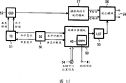
Describe below according to image pick up equipment of the present invention, the distance calculating method that this image pick up equipment is furnished with the invention described above utilized is proofreaied and correct the function of ambient light decay etc. in real time.Here, for example, Figure 12 has shown the signal processing structure of the digital camera of the function of being furnished with real-time correction ambient light decay etc.
In Figure 12,, for example, come the horizontal reset signal and the vertical reset signal of automatic signal generator (SG) 50 to offer timing generator (TG) 51, the signal that horizontal drive signals that timing generator 51 is generated and vertical driving signal offer semiconductor image pickup device (CCD) 52 and read each pixel of experience image pickup according to horizontal drive signals and vertical driving signal from timing generator 51.
Also leveler numerical value and vertimeter numerical value are fed to distance calculation module 53 from signal generator 50.Meanwhile, the optical axis center positional information is fed to distance calculation module 53 from end points 54, so that distance calculation module 53 is carried out distance calculation according to the distance calculating method of the invention described above.That is to say,, being fed to distance calculation module 53 from signal generator 50, and calculate distance apart from the optical axis center position with corresponding leveler numerical value of pixel and vertimeter numerical value for each pixel of from semiconductor image pickup device 52, reading.
The distance value from each pixel to the optical axis center distance from distance calculation module 53 be fed to look into the table (LUT) 55.From looking into the correction coefficient of finding range correction ambient light decay according to distance optical axis center position etc. the table 55, these correction coefficient are offered correction module 56, with distance, carry out the correction of ambient light decay etc. for the signal of each pixel of from semiconductor image pickup device 52, reading according to distance optical axis center position.
Should be noted that correction module 65 is made up of the multiplier that is used to multiply by correction coefficient usually, still, adder also can be used in by adding in the situation that deviant proofreaies and correct.Can also comprise the correction of carrying out except the ambient light correction for attenuation, such as the circuit of the correction of bleeding.Also correction module 56 calibrated signal offer camera signal processing module 57, in camera signal processing module 57, the picture signal of supply is carried out interpolation and synchronous etc., so that form from the output image signal (Y/C output signal) of end points 58 outputs.
Therefore, by means of present embodiment, the formula that utilizes polygonal approximation to calculate distance is used to calculate and calculated distance value like this is used for correcting lens shade etc.Like this, utilize simple hardware construction just can suitably calculate distance, and, the calculated distance value utilized, suitably correcting lens shade etc.
Like this, the invention solves when realizing the distance calculation device by hardware, the tradition distance calculation need very large circuit structure, can not be with oversimplifying that hardware calculates distance accurately and under the situation that size changes or reading method changes of image pickup units, for example, when skipping pixel, can not correctly obtain apart from the problem of the distance of optical axis.
Figure 13 has shown to be furnished with situation about skipping in the vertical/horizontal direction for as mentioned above, proofreaies and correct the signal processing structure of digital camera of the function of ambient light decay etc. in real time.
In this case, as shown in figure 13, transducer 40 (or multiplier 42) is installed in distance calculation module 53 inside, and according to changing from the information of skipping of the end points 41 supply inverse of the skip rate of end points 43 supplies (or from).Like this, count value is converted to the count value of situation about not skipping, can correctly obtain distance, thereby can suitably carry out the correction of lens shade etc. apart from optical axis.
Above-mentioned looking into table 55 also can have, and for example, obtains the structure of the correction coefficient that is used to proofread and correct ambient light decay etc. for the distance value of distance optical axis center.Configuration in this case is presented among Figure 14, wherein has been equipped with the computing module 59 that is used for correction coefficient f (d), replaces above-mentioned looking into table 55.In this case, also can utilize suitably correcting lens shade etc. of calculated distance value.
In the above among the embodiment, for example, as shown in figure 15, also can be provided in the correction module of changing 56 after the video camera information processing module 57.In this case, proofread and correct afterwards resolving into luminance signal (Y-signal) and color difference signal (Cb, Cr signal), so that can, for example, by luminance signal being carried out the ambient light correction for attenuation and color difference signal being carried out bleeding proofread and correct, respectively luminance signal and color difference signal are proofreaied and correct.
In addition, for example, as shown in figure 16, such correction module 56 can be provided in, for example, after the color interpolation processing module 60 in the camera signal processing module 57,, just can carry out the correction of lens shade so that in case obtained the color signal of three primary colors (R, G, B) for all pixels by interpolation.In being furnished with the equipment of several image pickup devices, for example, as shown in figure 17, can be provided as each correction module of proofreading and correct 61 of image pickup device 52R, 52G and 52B.
In aforesaid embodiment, look into table 55 in each case and all realize by individual module, but, look into also can store respectively and be used for three primary colors (R, G, B) or be the value of luminance signal (Y-signal) and color difference signal (Cb, Cr signal) with table 55.
Should be noted that image pick up equipment of the present invention is described as the digital static video camera that is applied to take usually rest image, still, by utilizing the ability of real-time calculating distance, the present invention also can be applied to the digital video camcorder of taking moving image.
The input of the XY coordinate of above-mentioned distance calculating method reception arbitrfary point and the XY coordinate of required point, and the distance between calculating arbitrfary point and the required point, and, by utilizing approaching of the arbitrary polygon on the meaning point in office of center calculated required point, can utilize the hardware simplicity structure to carry out the suitable calculating of distance.By utilizing calculated distance value in this manner, can be in the equipment real-time treatment for correcting of needs, such as digital camera correcting lens shade etc. suitably.
In addition, above-mentioned image pick up equipment comprises lens combination and according to the XY coordinate system image pickup units of output signal therefrom, and contain the distance calculation device, the input of the corresponding XY coordinate of optical axis of reception of distance calculation device and lens combination and the XY coordinate of required point, with utilize by the center with the corresponding point of optical axis on the arbitrary polygon approximate calculation to the computational methods of the distance of required point, calculate and corresponding point of optical axis and required point between distance.Be used for proofreading and correct at least because the shade relevant that lens combination causes by distance calculation device calculated distance value with ambient light decay, thereby except suitably calculate distance by simple hardware construction, can also utilize suitably correcting lens shade etc. of calculated distance value.
Should be noted that, the invention is not restricted to the foregoing description, under the situation that does not depart from scope of the present invention, can carry out various modifications the foregoing description.
That is to say, by means of distance calculating method of the present invention, by utilizing polygonal approximation to calculate the calculating of distance, calculate distance, thereby can utilize the hardware simplicity structure suitably to calculate distance, with by utilizing the calculated distance value, can in the equipment real-time treatment for correcting of needs, such as digital camera, suitably carry out the correction of lens shade etc.
According to the present invention, be set as x and the distance on the Y reference axis is set as y in the distance on the X reference axis between arbitrfary point and the required point, polygon is set as 16 limit shapes, with utilize approximate formula (x+y)+A|x-y|+B[|2x-y|+|x-2y|] carry out distance calculation, thereby can utilize simple hardware construction suitably to calculate distance.
In addition,, when polygonal approximation, any approximation is calculated distance as coefficient by means of the present invention, thus can utilize in addition more simple hardware construction suitably calculate distance.
In addition,, utilize the value of A=3/16 and B=1/8 to calculate distance, thereby can utilize the polarization simple hardware construction suitably to calculate distance as coefficient value by means of the present invention.
In addition, by means of the present invention, when compressing or expanding any processing of XY coordinate,, can utilize simple hardware construction suitably to calculate distance by according to compression ratio or ratio conversion input value x and y calculating distance.
In addition, by means of the present invention, be set as x and the distance on the Y reference axis is set as y in the distance on the X reference axis between arbitrfary point and the required point, polygon is set as 8 limit shapes, with utilize approximate formula (x+y)+C|x-y| to carry out distance calculation, thereby can utilize in addition more simple hardware construction suitably calculate distance.
In addition,, when polygonal approximation, any approximation is calculated distance as coefficient by means of the present invention, thus can utilize in addition more simple hardware construction suitably calculate distance.
In addition,, utilize the value of C=1/2 to calculate distance, thereby can utilize extremely simple hardware construction suitably to calculate distance as coefficient value by means of the present invention.
In addition, by means of the present invention, when compressing or expanding any processing of XY coordinate,,, also can utilize simple hardware construction suitably to calculate distance even skip coordinate by according to compression ratio or ratio conversion input value x and y calculating distance.
In addition, by means of image pick up equipment of the present invention, carry out distance calculation by utilizing polygon to calculate approximation, with the calculated distance value is used for correcting lens shade etc., thereby can utilize the hardware simplicity structure suitably to calculate distance, with by utilizing the calculated distance value, can suitably carry out the correction of lens shade etc.
In addition, by means of the present invention, be set as x and the distance on the Y reference axis is set as y in the distance on the X reference axis on the image pickup units and between corresponding point of the optical axis of lens combination and the required point, polygon is set as 16 limit shapes, with utilize approximate formula (x+y)+A|x-y|+B[|2x-y|+|x-2y|] carry out distance calculation, thereby utilize simple hardware construction suitably to calculate distance and can utilize suitably correcting lens shade etc. of calculated distance value.
In addition,, when polygonal approximation, any approximation is calculated distance as coefficient by means of the present invention, thus can utilize in addition more simple hardware construction suitably calculate distance and can utilize suitably correcting lens shade etc. of calculated distance value.
In addition,, utilize the value of A=3/16 and B=1/8 to calculate distance, thereby can utilize very simple hardware construction suitably to calculate distance and can utilize suitably correcting lens shade etc. of calculated distance value as coefficient value by means of the present invention.
In addition, by means of the present invention, when utilizing skipping arbitrarily on the XY reference axis to carry out signal reading from image pickup units, after presetting skip rate conversion input value x and y, calculating distance, even thereby under situation about skipping, also can utilize simple hardware construction suitably to calculate distance and can utilize suitably correcting lens shade etc. of calculated distance value.
In addition, by means of the present invention, be set as x and the distance on the Y reference axis is set as y in the distance on the X reference axis on the image pickup units and between corresponding point of the optical axis of lens combination and the required point, polygon is set as 8 limit shapes, with utilize approximate formula (x+y)+C|x-y| to carry out distance calculation, thereby can utilize in addition more simple hardware construction suitably calculate distance and can utilize suitably correcting lens shade etc. of calculated distance value.
In addition,, when polygonal approximation, any approximation is calculated distance as coefficient by means of the present invention, thus can utilize in addition more simple hardware construction suitably calculate distance and can utilize suitably correcting lens shade etc. of calculated distance value.
In addition,, utilize the value of C=1/2 to calculate distance, thereby can utilize extremely simple hardware construction suitably to calculate distance and can utilize suitably correcting lens shade etc. of calculated distance value as coefficient value by means of the present invention.
In addition, by means of the present invention, when utilizing skipping arbitrarily on the XY reference axis to carry out signal reading from image pickup units, after presetting skip rate conversion input value x and y, calculating distance, even thereby under situation about skipping, also can utilize simple hardware construction suitably to calculate distance and can utilize suitably correcting lens shade etc. of calculated distance value.
Like this, the invention solves by means of conventional method and equipment, when realizing the distance calculation device by hardware, distance calculation need very large circuit structure, can not be with oversimplifying that hardware calculates distance accurately and for the situation that size changes or reading method changes of image pickup units, for example, when skipping, can not correctly obtain apart from the problem of the distance of optical axis.
Claims (6)
1. one kind contains lens combination and therefrom obtains the image pick up equipment of the image pickup units of signal according to the XY coordinate, comprising:
The distance calculation device, be used to receive input with the XY coordinate of the XY coordinate of the corresponding point of the optical axis of lens combination and required point, with utilize by the center with the corresponding point of optical axis on the formula of the required point of arbitrary polygon approximate calculation, distance between calculating and corresponding point of optical axis and the required point
Wherein, on the image pickup units and between corresponding point of the optical axis of lens combination and the required point the distance value of the being set as x on the X reference axis and and the corresponding point of optical axis of lens combination and required point between the distance value of being set as y on the Y reference axis,
Polygon is 16 limit shapes,
And utilization
(x+y)+A|x-y|+B[|2x-y|+|x-2y|]
As approximate formula and utilize A=3/16 and B=1/8 carries out distance calculation as coefficient, and
At least be used to proofread and correct because the shade relevant that lens combination causes by distance calculation device calculated distance value with ambient light decay.
2. image pick up equipment according to claim 1,
Wherein, when polygonal approximation, any approximation is calculated distance as coefficient.
3. image pick up equipment according to claim 1,
Wherein, when skipping arbitrarily according to the XY coordinate when image pickup units is obtained Signal Processing, by changing input value x in advance according to skip rate and y carries out distance calculation.
4, a kind ofly contain lens combination and therefrom obtain the image pick up equipment of the image pickup units of signal according to the XY coordinate, comprising:
The distance calculation device, be used to receive input with the XY coordinate of the XY coordinate of the corresponding point of the optical axis of lens combination and required point, with utilize by the center with the corresponding point of optical axis on the formula of the required point of arbitrary polygon approximate calculation, distance between calculating and corresponding point of optical axis and the required point
Wherein, on the image pickup units and between corresponding point of the optical axis of lens combination and the required point the distance value of the being set as x on the X reference axis and and the corresponding point of optical axis of lens combination and required point between the distance value of being set as y on the Y reference axis,
Polygon is 8 limit shapes,
And utilization
(x+y)+C|x-y|
As approximate formula and utilize C=1/2 to carry out distance calculation as coefficient, and
At least be used to proofread and correct because the shade relevant that lens combination causes by distance calculation device calculated distance value with ambient light decay.
5. image pick up equipment according to claim 4,
Wherein, when polygonal approximation, any approximation is carried out distance calculation as coefficient.
6. image pick up equipment according to claim 4,
Wherein, when carrying out any bypass signal according to the XY coordinate during, by changing input value x in advance according to skip rate and y carries out distance calculation from the processing of obtaining of image pickup units.
Applications Claiming Priority (3)
| Application Number | Priority Date | Filing Date | Title |
|---|---|---|---|
| JP14852/01 | 2001-01-23 | ||
| JP2001014852A JP2002216136A (en) | 2001-01-23 | 2001-01-23 | Distance calculating method and imaging system |
| JP14852/2001 | 2001-01-23 |
Publications (2)
| Publication Number | Publication Date |
|---|---|
| CN1457472A CN1457472A (en) | 2003-11-19 |
| CN1244236C true CN1244236C (en) | 2006-03-01 |
Family
ID=18881490
Family Applications (1)
| Application Number | Title | Priority Date | Filing Date |
|---|---|---|---|
| CNB028004752A Expired - Fee Related CN1244236C (en) | 2001-01-23 | 2002-01-23 | Distance calculating method and imaging pick up device |
Country Status (7)
| Country | Link |
|---|---|
| US (1) | US7317482B2 (en) |
| EP (1) | EP1355272A4 (en) |
| JP (1) | JP2002216136A (en) |
| KR (1) | KR100852306B1 (en) |
| CN (1) | CN1244236C (en) |
| TW (1) | TW548992B (en) |
| WO (1) | WO2002059837A1 (en) |
Families Citing this family (16)
| Publication number | Priority date | Publication date | Assignee | Title |
|---|---|---|---|---|
| US7388610B2 (en) | 2002-08-16 | 2008-06-17 | Zoran Corporation | Techniques of modifying image field data by extrapolation |
| US7408576B2 (en) | 2002-08-16 | 2008-08-05 | Zoran Corporation | Techniques for modifying image field data as a function of radius across the image field |
| US7391450B2 (en) * | 2002-08-16 | 2008-06-24 | Zoran Corporation | Techniques for modifying image field data |
| WO2005043891A1 (en) * | 2003-10-31 | 2005-05-12 | Mitsubishi Denki Kabushiki Kaisha | Image correcting method and imaging apparatus |
| JP4104571B2 (en) * | 2004-03-29 | 2008-06-18 | 三洋電機株式会社 | Distortion correction apparatus and imaging apparatus provided with the distortion correction apparatus |
| KR100615277B1 (en) * | 2004-08-18 | 2006-08-25 | 엠텍비젼 주식회사 | Method and apparatus for compensating Image sensor lens shading |
| JP2006148213A (en) * | 2004-11-16 | 2006-06-08 | Matsushita Electric Ind Co Ltd | Video processing apparatus |
| US7580070B2 (en) * | 2005-03-31 | 2009-08-25 | Freescale Semiconductor, Inc. | System and method for roll-off correction in image processing |
| JP4571038B2 (en) * | 2005-07-27 | 2010-10-27 | 三菱電機株式会社 | Image correction device |
| KR100808493B1 (en) * | 2005-12-28 | 2008-03-03 | 엠텍비젼 주식회사 | Lens shading compensation apparatus and method, and image processor using it |
| JP4940661B2 (en) * | 2006-01-11 | 2012-05-30 | ソニー株式会社 | Image processing apparatus, image processing method, and imaging apparatus |
| JP4476955B2 (en) * | 2006-03-17 | 2010-06-09 | 富士通マイクロエレクトロニクス株式会社 | Shading correction circuit and control method thereof |
| US20070236594A1 (en) * | 2006-03-31 | 2007-10-11 | Zafar Hasan | Techniques for radial fall-off correction |
| JP2009049609A (en) * | 2007-08-16 | 2009-03-05 | Fujitsu Microelectronics Ltd | Correcting circuit, correcting method, and image pick-up device |
| JP5206174B2 (en) * | 2008-07-08 | 2013-06-12 | 株式会社リコー | Zoom lens, camera, and portable information terminal device |
| US20130027548A1 (en) * | 2011-07-28 | 2013-01-31 | Apple Inc. | Depth perception device and system |
Family Cites Families (14)
| Publication number | Priority date | Publication date | Assignee | Title |
|---|---|---|---|---|
| JPH07107710B2 (en) * | 1985-08-08 | 1995-11-15 | 富士通株式会社 | Two-dimensional distance calculation device for image processing device |
| US6201574B1 (en) * | 1991-05-13 | 2001-03-13 | Interactive Pictures Corporation | Motionless camera orientation system distortion correcting sensing element |
| JP3191354B2 (en) * | 1991-11-15 | 2001-07-23 | ソニー株式会社 | Shading correction circuit |
| US5566245A (en) * | 1993-03-09 | 1996-10-15 | United Parcel Service Of America, Inc. | The performance of a printer or an imaging system using transform-based quality measures |
| JPH07104287B2 (en) * | 1993-03-29 | 1995-11-13 | 東洋ガラス株式会社 | Inspection method for minute defects of transparent object with curved surface |
| JPH08256295A (en) * | 1994-12-21 | 1996-10-01 | Olympus Optical Co Ltd | Image processing unit |
| EP0720125B1 (en) * | 1994-12-29 | 2002-05-08 | Koninklijke Philips Electronics N.V. | Image forming apparatus and method for correcting optical geometrical distortions in an image |
| US5703604A (en) * | 1995-05-22 | 1997-12-30 | Dodeca Llc | Immersive dodecaherdral video viewing system |
| JP2000125174A (en) * | 1998-10-12 | 2000-04-28 | Fuji Photo Film Co Ltd | Method and system for correcting distortion in image information |
| US6747702B1 (en) * | 1998-12-23 | 2004-06-08 | Eastman Kodak Company | Apparatus and method for producing images without distortion and lateral color aberration |
| US6538691B1 (en) * | 1999-01-21 | 2003-03-25 | Intel Corporation | Software correction of image distortion in digital cameras |
| JP3126955B2 (en) * | 1999-02-12 | 2001-01-22 | 株式会社アドバネット | Arithmetic unit for image conversion |
| US6833862B1 (en) * | 1999-06-30 | 2004-12-21 | Logitech, Inc. | Image sensor based vignetting correction |
| JP3624288B2 (en) * | 2001-09-17 | 2005-03-02 | 株式会社日立製作所 | Store management system |
-
2001
- 2001-01-23 JP JP2001014852A patent/JP2002216136A/en not_active Abandoned
-
2002
- 2002-01-14 TW TW091100392A patent/TW548992B/en not_active IP Right Cessation
- 2002-01-23 CN CNB028004752A patent/CN1244236C/en not_active Expired - Fee Related
- 2002-01-23 KR KR1020027012415A patent/KR100852306B1/en not_active IP Right Cessation
- 2002-01-23 WO PCT/JP2002/000462 patent/WO2002059837A1/en active Application Filing
- 2002-01-23 US US10/239,137 patent/US7317482B2/en not_active Expired - Fee Related
- 2002-01-23 EP EP02711216A patent/EP1355272A4/en not_active Withdrawn
Also Published As
| Publication number | Publication date |
|---|---|
| US20030156190A1 (en) | 2003-08-21 |
| US7317482B2 (en) | 2008-01-08 |
| KR20020086666A (en) | 2002-11-18 |
| JP2002216136A (en) | 2002-08-02 |
| WO2002059837A1 (en) | 2002-08-01 |
| TW548992B (en) | 2003-08-21 |
| EP1355272A4 (en) | 2009-07-15 |
| KR100852306B1 (en) | 2008-08-18 |
| CN1457472A (en) | 2003-11-19 |
| EP1355272A1 (en) | 2003-10-22 |
Similar Documents
| Publication | Publication Date | Title |
|---|---|---|
| CN1244236C (en) | Distance calculating method and imaging pick up device | |
| CN1097381C (en) | Photoelectric converting apparatus | |
| CN1086534C (en) | Image pickup device | |
| CN1220365C (en) | Screen correcting method and imaging device | |
| CN1251485C (en) | Camera device | |
| CN1209909C (en) | Image taking device | |
| CN1678035A (en) | Distortion correction device and image sensing device provided therewith | |
| CN1171465C (en) | Single chip type color camera with function of eliminating prodn. of pseudo-color | |
| CN1668085A (en) | Solid state image sensor and method of driving the same | |
| CN1744673A (en) | Video electronic flutter-proof device | |
| CN101064788A (en) | Solid state imaging device, method of driving solid state imaging device and image pickup apparatus | |
| CN1917616A (en) | Photographing apparatus | |
| CN1744674A (en) | Video electronic flutter-proof method | |
| CN1527591A (en) | Camera apparatus | |
| CN1308891C (en) | Apparatus and method for intensifying edge in picture processing | |
| CN1933540A (en) | Image processing apparatus and method for image resizing matching data supply speed | |
| CN1773361A (en) | Method and apparatus for removing noise from a digital image | |
| CN1153449C (en) | Image pickup device | |
| CN1738357A (en) | Camera system | |
| CN1225918C (en) | Image signal processor and method | |
| CN1992823A (en) | Signal processing apparatus | |
| CN1532939A (en) | Solid photographic device and its driving method | |
| CN1501111A (en) | Camera accessory | |
| CN1921566A (en) | Image pickup apparatus and image pickup method | |
| CN1604613A (en) | Imaging device |
Legal Events
| Date | Code | Title | Description |
|---|---|---|---|
| C06 | Publication | ||
| PB01 | Publication | ||
| C10 | Entry into substantive examination | ||
| SE01 | Entry into force of request for substantive examination | ||
| C14 | Grant of patent or utility model | ||
| GR01 | Patent grant | ||
| C17 | Cessation of patent right | ||
| CF01 | Termination of patent right due to non-payment of annual fee |
Granted publication date: 20060301 Termination date: 20100123 |