CN1240887A - Bearing assembly for pump - Google Patents
Bearing assembly for pump Download PDFInfo
- Publication number
- CN1240887A CN1240887A CN99105190A CN99105190A CN1240887A CN 1240887 A CN1240887 A CN 1240887A CN 99105190 A CN99105190 A CN 99105190A CN 99105190 A CN99105190 A CN 99105190A CN 1240887 A CN1240887 A CN 1240887A
- Authority
- CN
- China
- Prior art keywords
- pump
- bearing
- motor
- load module
- bearing load
- Prior art date
- Legal status (The legal status is an assumption and is not a legal conclusion. Google has not performed a legal analysis and makes no representation as to the accuracy of the status listed.)
- Granted
Links
Images


Classifications
-
- F—MECHANICAL ENGINEERING; LIGHTING; HEATING; WEAPONS; BLASTING
- F04—POSITIVE - DISPLACEMENT MACHINES FOR LIQUIDS; PUMPS FOR LIQUIDS OR ELASTIC FLUIDS
- F04B—POSITIVE-DISPLACEMENT MACHINES FOR LIQUIDS; PUMPS
- F04B53/00—Component parts, details or accessories not provided for in, or of interest apart from, groups F04B1/00 - F04B23/00 or F04B39/00 - F04B47/00
-
- F—MECHANICAL ENGINEERING; LIGHTING; HEATING; WEAPONS; BLASTING
- F04—POSITIVE - DISPLACEMENT MACHINES FOR LIQUIDS; PUMPS FOR LIQUIDS OR ELASTIC FLUIDS
- F04D—NON-POSITIVE-DISPLACEMENT PUMPS
- F04D29/00—Details, component parts, or accessories
- F04D29/04—Shafts or bearings, or assemblies thereof
- F04D29/046—Bearings
- F04D29/047—Bearings hydrostatic; hydrodynamic
-
- F—MECHANICAL ENGINEERING; LIGHTING; HEATING; WEAPONS; BLASTING
- F04—POSITIVE - DISPLACEMENT MACHINES FOR LIQUIDS; PUMPS FOR LIQUIDS OR ELASTIC FLUIDS
- F04D—NON-POSITIVE-DISPLACEMENT PUMPS
- F04D29/00—Details, component parts, or accessories
- F04D29/04—Shafts or bearings, or assemblies thereof
- F04D29/046—Bearings
- F04D29/0462—Bearing cartridges
-
- F—MECHANICAL ENGINEERING; LIGHTING; HEATING; WEAPONS; BLASTING
- F04—POSITIVE - DISPLACEMENT MACHINES FOR LIQUIDS; PUMPS FOR LIQUIDS OR ELASTIC FLUIDS
- F04D—NON-POSITIVE-DISPLACEMENT PUMPS
- F04D29/00—Details, component parts, or accessories
- F04D29/06—Lubrication
- F04D29/061—Lubrication especially adapted for liquid pumps
-
- F—MECHANICAL ENGINEERING; LIGHTING; HEATING; WEAPONS; BLASTING
- F16—ENGINEERING ELEMENTS AND UNITS; GENERAL MEASURES FOR PRODUCING AND MAINTAINING EFFECTIVE FUNCTIONING OF MACHINES OR INSTALLATIONS; THERMAL INSULATION IN GENERAL
- F16C—SHAFTS; FLEXIBLE SHAFTS; ELEMENTS OR CRANKSHAFT MECHANISMS; ROTARY BODIES OTHER THAN GEARING ELEMENTS; BEARINGS
- F16C2300/00—Application independent of particular apparatuses
- F16C2300/30—Application independent of particular apparatuses related to direction with respect to gravity
- F16C2300/34—Vertical, e.g. bearings for supporting a vertical shaft
Landscapes
- Engineering & Computer Science (AREA)
- Mechanical Engineering (AREA)
- General Engineering & Computer Science (AREA)
- Physics & Mathematics (AREA)
- Fluid Mechanics (AREA)
- Structures Of Non-Positive Displacement Pumps (AREA)
- Motor Or Generator Frames (AREA)
- Sliding-Contact Bearings (AREA)
Abstract
本发明涉及用于具有至少三个径向轴承的泵,特别是主冷却泵的轴承组件。其主要特征在于具有轴向轴承6’和径向轴承8的轴承装配组件19设置在泵3和驱动电机2之间。
The invention relates to a bearing assembly for a pump having at least three radial bearings, in particular a main cooling pump. Its main feature is that a bearing assembly 19 with an axial bearing 6 ′ and a radial bearing 8 is arranged between the pump 3 and the drive motor 2 .
Description
The present invention relates to have the bearing unit of the pump of at least three radial bearings, particularly Main Condensate Pump.
Known have two kinds of main bearing uniies to design, and they are used for the interior Main Condensate Pump of reactor cooling system of pressurized water reactor.In a kind of design, pump and motor are two devices that separate, and they are connected by flexible shaft coupling.In this case, pump and motor have two radial bearings and a cod respectively.This is called as four design bearing.In three design bearing, pump and motor have an axle, and above-mentioned flexible shaft coupling is omitted.Entire equipment has the cod and three radial bearings that are contained in motor top.
Pump is sent to water (when the proper functioning with 16 million pascals (Mpa) and 290 ℃) core the reactor cooling system of pressurized water reactor from steam generator.Multipole Sealing on the axle overcome barometric pressure with high pressure sealing in reactor cooling system.The pump housing is by seal casinghousing, and pump housing cover and main connecting bolt seal.The motor on motor housing and top is positioned on the pump housing cover.Axle has removable section in motor housing, and if required, it allows faster near sealing.
Under the assembling situation, removable section is a rigid coupling.Cod, the radial bearing of upper and lower generally are oil lubrication, and bottom radial bearing water lubrication.Provide lubricated by external means to bearing, perhaps, oil supplying device and this design form whole.This oil supplying device also is applicable to lube oil cooler.
This design means that the device of entire pump and motor must use always.When pump is tested, particularly use under the situation of Main Condensate Pump, this will cause significant disadvantages and high cost.
Therefore, the objective of the invention is that motor and motor also can separate and rotation sequentially, single fluid supply apparatus can be used for all bearing portions.
The present invention is characterized in that the bearing load module with cod and radial bearing is arranged between pump and the drive motor.This bearing load module cooperates with pump in a side, perhaps cooperates with motor at opposite side.As a result, also rotation separably of motor and pump.
Another advantage of the present invention is that oil feeding device and bearing load module form integral body and oil is provided can for entire equipment (pump and motor).
Favourable configuration of the present invention is characterized in that as needs bearing load module can be separated from staying part with the pump part, or it is separated from staying part with the motor part.This means that motor can be tested with the bearing load module on for example being contained in motor MANUFACTURER institute test bench on the one hand; On the other hand, less motor can be used for the test run of pump, is used for like this that the expense of test run becomes very low on the test bench.
Another advantage of the present invention is that service pump that all are essential and lube oil cooler and bearing unit form integral body.
Favourable configuration of the present invention is characterized in that bearing unit is applicable to four design bearing devices if motor housing is made some little changes.
With reference to the accompanying drawings, existing with case description the present invention.
Fig. 1 represents according to the Main Condensate Pump in the device of three bearings of prior art;
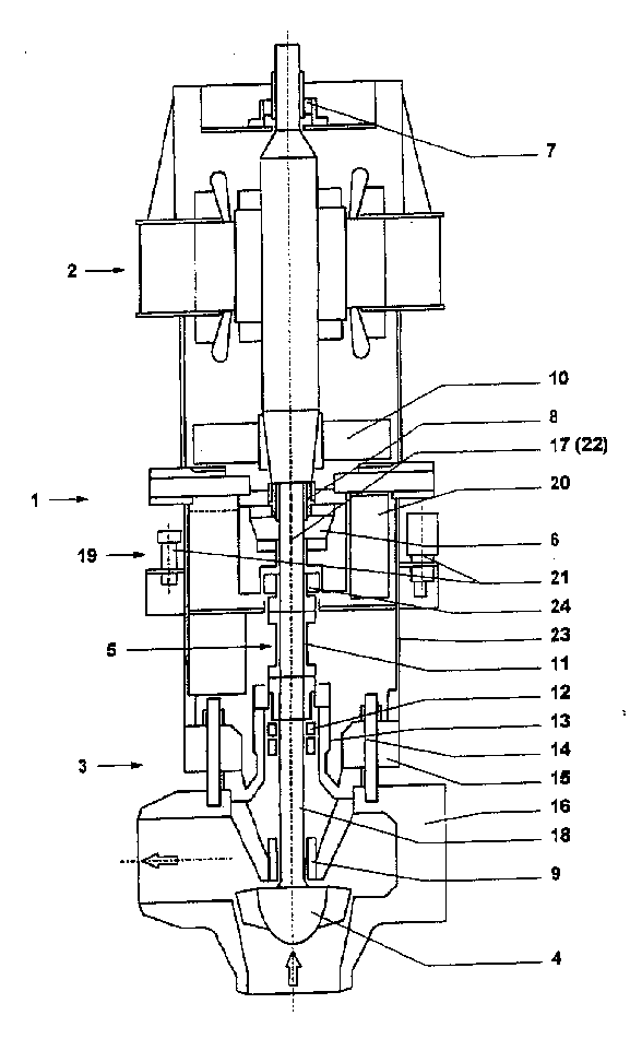
Fig. 2 represents according to Main Condensate Pump of the present invention;
Fig. 3 is the partial view according to bearing unit of the present invention;
Fig. 4 represents another kind of modified model of the present invention;
Fig. 5 represents a kind of four design bearing devices.
Fig. 1 represents the Main Condensate Pump according to prior art.Motor 2 is on top, and pump 3 is in the bottom.Pump impeller 4 is positioned on the single axle 5 of motor 2 and pump 3.Axle 5 is by 6 bearings of the cod in the motor zone.What be adjacent is top radial bearing 7.Middle part radial bearing 8 is positioned at the opposite side of motor 2.This bottom is by bottom radial bearing 9 supportings in pump zone.Flywheel 10 is positioned at the upper end of axle.For the ease of making motor break away from the pump housing 16 and can finishing pump 3 regular maintenances and repairing, axle 5 has detachable member 11, and detachable member 11 is actually the rigid coupling of 18 of a top 17 and axle bottoms; The axle top 17 pass motor 2 and the axle bottom 18 start from pump.Shaft seal 12 in the seal casinghousing 13 is used for sealing.Seal casinghousing 13 is fixed on the pump housing 16 by pump housing cover 15 and main connecting bolt 14.The drive motor 2 on motor housing 23 and top is positioned on the pump housing cover 15.Entire equipment 1 has single axial bearing 6 and three radial bearings 7,8,9 altogether on motor 2.Pump 3 is sent to water (when the proper functioning with 16 million pascals (Mpa) and 290 ℃) core the reactor cooling system of pressurized water reactor from steam generator.The multipole Sealing 12 of axle on 15 overcome barometric pressure with high pressure sealing in reactor cooling system.The pump housing 16 is by seal casinghousing 13, and pump housing cover 15 and main connecting bolt 14 seal.
Fig. 2 represents a kind of improvement of the present invention.Identical in this used reference number and Fig. 1.This figure also shows the device of three bearings and do not have shaft coupling between pump and motor.Different with Fig. 1, on the axle 5 between motor 2 and the pump 3, bearing load module 19 is set.This bearing load module 19 comprises middle part radial bearing 8 and cod 6 '.Cod 6 ' can be positioned at just in time under the middle part radial bearing 8 or be positioned at just in time on middle part radial bearing 8.In addition, lube oil cooler 20 and be contained in this bearing load module 19 to the service pump 21 of entire equipment fuel feeding.Between the middle part radial bearing 8 of flywheel 10 ' in motor 2 and motor zone.Use this design, when the motor that is connected with bearing load module 19 flanges 2 broke away from pumps zone 3, it can mechanically be detected.In this case, above-mentioned two zones are separated at detachable member 11 places.The combination of motor 2 and bearing load module 19 has two radial bearings 7,8 and a cod 6 ', and lubricated oil cooled all devices is also in aggregates.Pump part 3 can detect with bearing load module 19.Substituting part 22 is inserted in the bearing load module 19 to replace the suitable part on axle top 17.In addition, the combination of pump zone 3 and bearing load module 19 has two radial bearings 8,9 and a cod 6 '.Also can provide oil supplying device.Fig. 3 also shows bearing load module 19 and each member.The high axial force (normally pointing to down) of the rotor 4 that is produced by the pressure in the reactor cooling system (about 160 crust) is through cod 6 ' and motor housing 23, then in the pump housing 16 that turns to by pump housing cover 15 and main connecting bolt 14.The rotor and the stator that this means motor 2 no longer are subjected to strong axial force, and the distortion that axial force causes is less, and the distance that friction connects is shorter.
Owing to be transferred the elevated operating temperature (290 °) of water, also should consider thermal distortion.If the distance that friction connects is shorter, in the axial direction differential strain also is less between static and rotational parts.
As a result, the differential strain scope that forms in the axial direction between static and rotational parts keeps less at the thermal region of pump 3.Determined adjustment size when may not request assembly equipment.This helps interchangeability of parts.
The feedway 24 of oil is contained on the axle 15 at the minimum point place of the circulatory system of oil, and it supplies with all lubricated positions with new oil.This preferably obtains by boring.Under impossible or irrealizable situation, obtain (radial bearing that for example, is used for top) by oil pipe.
Like this, the motor 2 (axle 15 be separated in detachable member 11) that has bearing load module 19 can for example rotate on the test stand of motor MANUFACTURER individually.Usually, the MANUFACTURER of pump and motor is different.
Equally, replace at replaced 22 of the shaft portion of 11 of flywheel 10 ' and detachable member if bearing load module 19 is contained on the pump 3, pump 3 can rotate on test stand individually.This test bench running is not used for detecting hydraulic data but all mechanical properties of testing apparatus.In this case, the impeller of former impeller with lower-wattage input (in the scope of the 5-10% of former input) replaces.
As a result, less motor can be used for the laboratory of pump 3 and detects running, can make the test run expense of test bench keep lower like this.
Fig. 4 represents a kind of possible design of relevant bearing load module 19, and radial bearing 8 is positioned on the cod 6 '.The middle part radial bearing can be installed under cod 6 '.Therefore, the position of middle part radial bearing 8 can be used for influencing the intrinsic corner frequency of rotor.
Fig. 5 represents the design apparatus of four (radially) bearings.Different with Fig. 4, it has the additional space of flexible shaft coupling 25, and additional new oil is supplied with shaft coupling 25.
Claims (6)
1. the bearing unit of pump, particularly Main Condensate Pump, it has at least three radial bearings, it is characterized in that the bearing load module (19) that has cod (6 ') and radial bearing (8) is arranged between pump (3) and the drive motor (2).
2. according to the bearing unit of claim 1, it is whole to it is characterized in that oil feeding device (20,21) and bearing load module (19) form.
3. according to the bearing unit of claim 1 or 2, it is characterized in that oil feeding device (20,21) provides oil can for entire equipment (1) (pump (3) and motor (2)).
4. according to the bearing unit of claim 1 or 3, it is characterized in that bearing load module (19) on demand can with stay part discretely, and operate together together or with motor part (2,17) with pump part (3,15,16,18).
5. according to the bearing unit of claim 1 or 4, it is whole to it is characterized in that each essential service pump (21) and lube oil cooler (20) and this bearing load module (19) form.
6. according to the bearing unit of claim 1 or 5, it is characterized in that this bearing load module (19) is applicable to the device of four (radially) bearings.
Applications Claiming Priority (2)
| Application Number | Priority Date | Filing Date | Title |
|---|---|---|---|
| AT0069198A AT412664B (en) | 1998-04-27 | 1998-04-27 | STORAGE FOR A PUMP, ESPECIALLY MAIN COOLANT PUMP |
| ATA691/98 | 1998-04-27 |
Publications (2)
| Publication Number | Publication Date |
|---|---|
| CN1240887A true CN1240887A (en) | 2000-01-12 |
| CN1270100C CN1270100C (en) | 2006-08-16 |
Family
ID=3497287
Family Applications (1)
| Application Number | Title | Priority Date | Filing Date |
|---|---|---|---|
| CNB991051904A Expired - Lifetime CN1270100C (en) | 1998-04-27 | 1999-04-26 | Bearing assembly for pump |
Country Status (6)
| Country | Link |
|---|---|
| JP (1) | JP2000027855A (en) |
| KR (1) | KR100562093B1 (en) |
| CN (1) | CN1270100C (en) |
| AT (1) | AT412664B (en) |
| DE (1) | DE19916067B4 (en) |
| FR (1) | FR2777956B1 (en) |
Cited By (1)
| Publication number | Priority date | Publication date | Assignee | Title |
|---|---|---|---|---|
| CN104653508A (en) * | 2015-02-15 | 2015-05-27 | 沈阳耐蚀合金泵股份有限公司 | Pump with lubricating oil circular supply system |
Families Citing this family (4)
| Publication number | Priority date | Publication date | Assignee | Title |
|---|---|---|---|---|
| DE10314526B4 (en) * | 2003-03-31 | 2007-11-29 | Geräte- und Pumpenbau GmbH Dr. Eugen Schmidt | Coolant pump, in particular flow-cooled electric coolant pump with integrated directional control valve |
| DE102009005154A1 (en) * | 2009-01-15 | 2010-07-22 | Wilo Se | Device for connecting an electromotive drive unit with a pump unit |
| US8602753B2 (en) * | 2009-09-21 | 2013-12-10 | Flowserve Management Company | Radial bearings for deep well submersible pumps |
| KR101409881B1 (en) | 2011-12-30 | 2014-06-20 | 두산중공업 주식회사 | Coolant pump assembly |
Family Cites Families (10)
| Publication number | Priority date | Publication date | Assignee | Title |
|---|---|---|---|---|
| CH507452A (en) * | 1969-09-01 | 1971-05-15 | Rheinhuette Vorm Beck & Co | Vertical self-regulating centrifugal pump |
| DE2227357B2 (en) * | 1972-06-06 | 1976-07-01 | Klein, Schanziin & Becker AG, 6710 Frankenthal | REACTOR PUMP DRIVE |
| DE2301961A1 (en) * | 1973-01-16 | 1974-07-18 | Klein Schanzlin & Becker Ag | VERTICAL CENTRIFUGAL PUMP WITH SEPARABLE SHAFT |
| AT329972B (en) * | 1974-08-20 | 1976-06-10 | Andritz Ag Maschf | MAIN COOLANT PUMP |
| US3975117A (en) * | 1974-09-27 | 1976-08-17 | James Coolidge Carter | Pump and motor unit with inducer at one end and centrifugal impeller at opposite end of the motor |
| DE3108764C2 (en) * | 1981-03-07 | 1983-12-29 | Brown Boveri Reaktor GmbH, 6800 Mannheim | Safety device to avoid overspeeding of the drive motor of a primary coolant pump of a water-cooled nuclear reactor plant |
| US4913563A (en) * | 1988-11-07 | 1990-04-03 | Westinghouse Electric Corp. | Hydrodynamic pivoted pad bearing assembly for a reactor coolant pump |
| FR2649165B1 (en) * | 1989-06-29 | 1994-07-08 | Jeumont Schneider | WHEEL-SHAFT CONNECTION, IN PARTICULAR FOR A COOLING PUMP OF A NUCLEAR REACTOR |
| FR2660375B1 (en) * | 1990-03-30 | 1995-04-21 | Pecquet Tesson Soc Ind | CIRCULATION PUMP OF A CLOSED CIRCUIT HEAT LIQUID. |
| DE4011477C2 (en) * | 1990-04-09 | 1997-04-17 | Klein Schanzlin & Becker Ag | Lantern |
-
1998
- 1998-04-27 AT AT0069198A patent/AT412664B/en not_active IP Right Cessation
-
1999
- 1999-04-09 DE DE19916067A patent/DE19916067B4/en not_active Expired - Lifetime
- 1999-04-20 FR FR9904961A patent/FR2777956B1/en not_active Expired - Lifetime
- 1999-04-26 CN CNB991051904A patent/CN1270100C/en not_active Expired - Lifetime
- 1999-04-26 KR KR1019990014894A patent/KR100562093B1/en not_active Expired - Lifetime
- 1999-04-26 JP JP11117758A patent/JP2000027855A/en active Pending
Cited By (1)
| Publication number | Priority date | Publication date | Assignee | Title |
|---|---|---|---|---|
| CN104653508A (en) * | 2015-02-15 | 2015-05-27 | 沈阳耐蚀合金泵股份有限公司 | Pump with lubricating oil circular supply system |
Also Published As
| Publication number | Publication date |
|---|---|
| DE19916067B4 (en) | 2005-07-14 |
| FR2777956A1 (en) | 1999-10-29 |
| AT412664B (en) | 2005-05-25 |
| ATA69198A (en) | 2004-10-15 |
| CN1270100C (en) | 2006-08-16 |
| KR19990083485A (en) | 1999-11-25 |
| DE19916067A1 (en) | 1999-11-04 |
| FR2777956B1 (en) | 2005-09-02 |
| JP2000027855A (en) | 2000-01-25 |
| KR100562093B1 (en) | 2006-03-17 |
Similar Documents
| Publication | Publication Date | Title |
|---|---|---|
| Mayer | Mechanical seals | |
| Bloch et al. | Compressors and modern process applications | |
| US8579608B2 (en) | Fluid energy machine | |
| US7044217B2 (en) | Stuffing box for progressing cavity pump drive | |
| EP2279114B1 (en) | Propulsion and bearing arrangement for a ship and bearing arrangement | |
| US20040005228A1 (en) | Motor driven centrifugal compressor/blower | |
| US11415169B2 (en) | Multiphase pump | |
| US20080206076A1 (en) | Vertical Pump Arrangement | |
| CA2629278C (en) | Stuffing box for progressing cavity pump drive | |
| WO2008105831A2 (en) | Turbine engine, seal therefor and method of removing a seal from a turbine engine | |
| KR102193340B1 (en) | Primary circulating pump assembly | |
| CN1240887A (en) | Bearing assembly for pump | |
| Bloch et al. | Major process equipment maintenance and repair | |
| CN101666316B (en) | Auxiliary water supply electric pump in nuclear power plant | |
| RU2485352C1 (en) | Oil delivery rotary pump with rotor running in antifriction bearings and method of improving pump performances | |
| EP2742243B1 (en) | Pump shaft seal using sealing rings and a bellows for retention of bearing lubricant | |
| JP5246956B2 (en) | Vertical shaft pump | |
| US7318707B2 (en) | Support bearing for a vertically arranged centrifugal pump | |
| Kraevskii et al. | Procedures and Practice for Raising Reliability of Dynamic Equipment. | |
| Almasi | Optimizing Reciprocating Compressors for CPI Plants. | |
| Struck et al. | Ensuring integrally-geared compressor reliability with API 617 | |
| Leith et al. | Paper 4: Advanced-Class Boiler Feed Pumps for 660-Mw Generators | |
| Larralde et al. | Selection of gas compressors: part 4 | |
| Lorenzen et al. | Solid Couplings With Flexible Intermediate Shafts For High Speed Turbocompressor Trains. | |
| Sembler | The Design and Operation of Pumps Furnished for Marine Cargo Service: Part II |
Legal Events
| Date | Code | Title | Description |
|---|---|---|---|
| C06 | Publication | ||
| PB01 | Publication | ||
| C10 | Entry into substantive examination | ||
| SE01 | Entry into force of request for substantive examination | ||
| C14 | Grant of patent or utility model | ||
| GR01 | Patent grant | ||
| CX01 | Expiry of patent term | ||
| CX01 | Expiry of patent term |
Granted publication date: 20060816 |