CN1237737C - Transmission using antenna array in CDMA communication system - Google Patents
Transmission using antenna array in CDMA communication system Download PDFInfo
- Publication number
- CN1237737C CN1237737C CNB008126372A CN00812637A CN1237737C CN 1237737 C CN1237737 C CN 1237737C CN B008126372 A CNB008126372 A CN B008126372A CN 00812637 A CN00812637 A CN 00812637A CN 1237737 C CN1237737 C CN 1237737C
- Authority
- CN
- China
- Prior art keywords
- signal
- weighting
- pilot signal
- data
- version
- Prior art date
- Legal status (The legal status is an assumption and is not a legal conclusion. Google has not performed a legal analysis and makes no representation as to the accuracy of the status listed.)
- Expired - Fee Related
Links
Images


Classifications
-
- H—ELECTRICITY
- H04—ELECTRIC COMMUNICATION TECHNIQUE
- H04B—TRANSMISSION
- H04B1/00—Details of transmission systems, not covered by a single one of groups H04B3/00 - H04B13/00; Details of transmission systems not characterised by the medium used for transmission
- H04B1/69—Spread spectrum techniques
- H04B1/707—Spread spectrum techniques using direct sequence modulation
- H04B1/7097—Interference-related aspects
- H04B1/711—Interference-related aspects the interference being multi-path interference
- H04B1/7115—Constructive combining of multi-path signals, i.e. RAKE receivers
- H04B1/712—Weighting of fingers for combining, e.g. amplitude control or phase rotation using an inner loop
-
- H—ELECTRICITY
- H04—ELECTRIC COMMUNICATION TECHNIQUE
- H04B—TRANSMISSION
- H04B7/00—Radio transmission systems, i.e. using radiation field
- H04B7/02—Diversity systems; Multi-antenna system, i.e. transmission or reception using multiple antennas
- H04B7/04—Diversity systems; Multi-antenna system, i.e. transmission or reception using multiple antennas using two or more spaced independent antennas
- H04B7/06—Diversity systems; Multi-antenna system, i.e. transmission or reception using multiple antennas using two or more spaced independent antennas at the transmitting station
- H04B7/0613—Diversity systems; Multi-antenna system, i.e. transmission or reception using multiple antennas using two or more spaced independent antennas at the transmitting station using simultaneous transmission
- H04B7/0615—Diversity systems; Multi-antenna system, i.e. transmission or reception using multiple antennas using two or more spaced independent antennas at the transmitting station using simultaneous transmission of weighted versions of same signal
- H04B7/0619—Diversity systems; Multi-antenna system, i.e. transmission or reception using multiple antennas using two or more spaced independent antennas at the transmitting station using simultaneous transmission of weighted versions of same signal using feedback from receiving side
- H04B7/0621—Feedback content
- H04B7/0634—Antenna weights or vector/matrix coefficients
-
- H—ELECTRICITY
- H04—ELECTRIC COMMUNICATION TECHNIQUE
- H04B—TRANSMISSION
- H04B7/00—Radio transmission systems, i.e. using radiation field
- H04B7/02—Diversity systems; Multi-antenna system, i.e. transmission or reception using multiple antennas
- H04B7/04—Diversity systems; Multi-antenna system, i.e. transmission or reception using multiple antennas using two or more spaced independent antennas
- H04B7/06—Diversity systems; Multi-antenna system, i.e. transmission or reception using multiple antennas using two or more spaced independent antennas at the transmitting station
- H04B7/0613—Diversity systems; Multi-antenna system, i.e. transmission or reception using multiple antennas using two or more spaced independent antennas at the transmitting station using simultaneous transmission
- H04B7/0678—Diversity systems; Multi-antenna system, i.e. transmission or reception using multiple antennas using two or more spaced independent antennas at the transmitting station using simultaneous transmission using different spreading codes between antennas
-
- H—ELECTRICITY
- H04—ELECTRIC COMMUNICATION TECHNIQUE
- H04B—TRANSMISSION
- H04B7/00—Radio transmission systems, i.e. using radiation field
- H04B7/02—Diversity systems; Multi-antenna system, i.e. transmission or reception using multiple antennas
- H04B7/04—Diversity systems; Multi-antenna system, i.e. transmission or reception using multiple antennas using two or more spaced independent antennas
- H04B7/08—Diversity systems; Multi-antenna system, i.e. transmission or reception using multiple antennas using two or more spaced independent antennas at the receiving station
- H04B7/0837—Diversity systems; Multi-antenna system, i.e. transmission or reception using multiple antennas using two or more spaced independent antennas at the receiving station using pre-detection combining
- H04B7/0842—Weighted combining
- H04B7/0848—Joint weighting
- H04B7/0854—Joint weighting using error minimizing algorithms, e.g. minimum mean squared error [MMSE], "cross-correlation" or matrix inversion
-
- H—ELECTRICITY
- H04—ELECTRIC COMMUNICATION TECHNIQUE
- H04B—TRANSMISSION
- H04B7/00—Radio transmission systems, i.e. using radiation field
- H04B7/02—Diversity systems; Multi-antenna system, i.e. transmission or reception using multiple antennas
- H04B7/04—Diversity systems; Multi-antenna system, i.e. transmission or reception using multiple antennas using two or more spaced independent antennas
- H04B7/08—Diversity systems; Multi-antenna system, i.e. transmission or reception using multiple antennas using two or more spaced independent antennas at the receiving station
- H04B7/0837—Diversity systems; Multi-antenna system, i.e. transmission or reception using multiple antennas using two or more spaced independent antennas at the receiving station using pre-detection combining
- H04B7/0842—Weighted combining
- H04B7/0848—Joint weighting
- H04B7/0857—Joint weighting using maximum ratio combining techniques, e.g. signal-to- interference ratio [SIR], received signal strenght indication [RSS]
-
- H—ELECTRICITY
- H04—ELECTRIC COMMUNICATION TECHNIQUE
- H04B—TRANSMISSION
- H04B7/00—Radio transmission systems, i.e. using radiation field
- H04B7/02—Diversity systems; Multi-antenna system, i.e. transmission or reception using multiple antennas
- H04B7/04—Diversity systems; Multi-antenna system, i.e. transmission or reception using multiple antennas using two or more spaced independent antennas
- H04B7/08—Diversity systems; Multi-antenna system, i.e. transmission or reception using multiple antennas using two or more spaced independent antennas at the receiving station
- H04B7/0891—Space-time diversity
-
- H—ELECTRICITY
- H04—ELECTRIC COMMUNICATION TECHNIQUE
- H04J—MULTIPLEX COMMUNICATION
- H04J13/00—Code division multiplex systems
- H04J13/0003—Code application, i.e. aspects relating to how codes are applied to form multiplexed channels
-
- H—ELECTRICITY
- H04—ELECTRIC COMMUNICATION TECHNIQUE
- H04B—TRANSMISSION
- H04B2201/00—Indexing scheme relating to details of transmission systems not covered by a single group of H04B3/00 - H04B13/00
- H04B2201/69—Orthogonal indexing scheme relating to spread spectrum techniques in general
- H04B2201/707—Orthogonal indexing scheme relating to spread spectrum techniques in general relating to direct sequence modulation
- H04B2201/70701—Orthogonal indexing scheme relating to spread spectrum techniques in general relating to direct sequence modulation featuring pilot assisted reception
-
- H—ELECTRICITY
- H04—ELECTRIC COMMUNICATION TECHNIQUE
- H04B—TRANSMISSION
- H04B7/00—Radio transmission systems, i.e. using radiation field
- H04B7/02—Diversity systems; Multi-antenna system, i.e. transmission or reception using multiple antennas
- H04B7/04—Diversity systems; Multi-antenna system, i.e. transmission or reception using multiple antennas using two or more spaced independent antennas
- H04B7/08—Diversity systems; Multi-antenna system, i.e. transmission or reception using multiple antennas using two or more spaced independent antennas at the receiving station
- H04B7/0837—Diversity systems; Multi-antenna system, i.e. transmission or reception using multiple antennas using two or more spaced independent antennas at the receiving station using pre-detection combining
- H04B7/0842—Weighted combining
- H04B7/0845—Weighted combining per branch equalization, e.g. by an FIR-filter or RAKE receiver per antenna branch
Abstract
The invention provides for transmission and reception of a data signal using a plurality of transmitting antennas. Each antenna transmits a different pilot signal having a pseudo random chip code sequence. A receiver filters each transmitted pilot using that pilot's chip code. The filtered pilots are weighted and combined. Each pilot signal's weight is adaptively adjusted in part on a signal quality of the combined signal. A data signal is transmitted such that different spread spectrum versions of the data signal are transmitted from each transmitting antenna. Each version having a different chip code identifier. Upon reception, each version is filtered with its associated chip code. The filtered versions are weighted in accordance with the adjusted weights associated with the pilot signal of the respective antenna.
Description
Technical field
The present invention generally is about the transmission of the signal in the wireless stroke of sign indicating number access communication system (code division multiple access) and receives.Especially refer to a kind of system and method that uses aerial array to receive with the signal that improves in the radio CDMA communications system.
Background technology
Fig. 1 represents a kind of known cdma communication system.This communication system has a plurality of base station 20-32.Each communication base station 20 uses exhibition frequency (spread spectrum) CDMA and user's equipment (EUs) 34-38 to communicate in its operating area.20 communications to each UE 43-38 are regarded as down link (downlink) communication from the base station, and 20 communication is regarded as up link (uplink) communication to the base station from each UE 34-38.
Represented among Fig. 2 is a CDMA transmitter and a receiver of simplifying.One data-signal with predetermined frequency range is mixed with generation it by a blender 40 by a pseudo-random chip codeword sequence (pseudo random chip code sequence) of the numerical digit spread spectrum signal of antenna 42 transmission usefulness.When signal when antenna 44 is received, this data are through being replicated in blender 46 with in order to the pseudo-random chip codeword sequence relevant (correlation) of transmission data is later.By using different pseudo-random chip codeword sequences, many data-signals use identical Channel Bandwidth.Especially, base station 20 will communicate a plurality of UE2 34-38 on identical frequency range.
For and a receiver between clock pulse synchronous, one not the pilot signal of modulation be used.This pilot signal allows a corresponding receiver and a permission data-signal of being scheduled to be gone the transmitter of expansion (despreading) synchronous at receiver.In typical C DMA system, each base station 20 is transmitted a single pilot signal that is received by all Ues 34-38 in the communication range and is transmitted so that synchronous forward direction chains (forward link).On the contrary, in some cdma system, for example in B-CDMATM air interface, each UE 34-38 transmits a single designated pilot signal and transmits with synchronous reverse link (reverse link)
When a UE 34-38 or a base station 20-32 received a signal specific, all signals in identical frequency range were the signals about the similar noise of this signal specific.The power level that increases by a signal all other signals in the identical frequency range that will fail.Yet, the power level reduction can be produced undesired received signals quality too much.A kind of in order to the index of measuring received signals be signal to noise ratio (signal to noise ratio, SNR).At receiver end, the size of described received signals is compared by the size with the noise that is received.Received data are easy to be reduced at receiver to have high SNR in transmission signals.Low SNR causes the loss of data.
In order to keep the signal to noise ratio of wanting in the transmission power level of minimum, most cdma system uses some adaptive power control forms.By reducing through-put power, the noise in the identical frequency range between the signal is lowered.Make that the maximum number of the received signals that is positioned at desirable signal to noise ratio place in the identical frequency range obtains increasing.
Though adaptive power control reduces the interference of the signal in the identical frequency range, the interference of restriction system capacity still exists.Same radio frequency is used in a kind of increase, and (radio frequency, RF) technology of the signal of frequency spectrum just is to use fanization (sectorization).In fanization, base station user tropism's antenna is so that be divided into several sections with the operating area of this base station.Make that interference between signals is lowered in different sections.Yet, in the same sector of identical frequency range, produce mutually between the signal and disturb.In addition, specified different frequency ranges to give the adjacent sections of the spectrum efficiency that reduces a predetermined frequency range usually by the base station of fanning.
The U.S. the 5th, 652, No. 74 patent discloses a kind of transmitter array system.The data-signal of antenna transmission one expansion (spread) of each array.Each data is expanded with different orthogonal code (orthogonal code).One receiver receives this spread data signal that is transmitted.This received signal uses orthogonal code to consider the ripple device by coupling or correlator is gone expansion.Gone a plurality of data-signals of expanding combined or select wherein one to be gone spread signal as received signals
EPO 881 781 A2 disclose a kind of transmit diversity framework.From a plurality of antenna transmission one message signals that concerning each antenna, use different extended codes.
The U.S. the 5th, 812, No. 542 patents disclose a kind of soft interchange (softhandoff) system of cdma system.Each base station transmits one pilot signal and identical data-signal of a plurality of base stations.Mobile unit receives this pilot signal and uses from the weighting message of pilot signal decision and remove to expand this identical data-signal.The equalized data signal that this quilt goes to expand is combined into an outputting data signals
Make, exist the signal quality of further improvement received signals and do not reduce the demand of the system of through-put power.
Summary of the invention
The invention provides the transmission and the reception of the data-signal that uses a plurality of transmit antennas.Each antenna transmission has the different pilot signal of a pseudo-random chip codeword sequence.One receiver filters each pilot signal that is transmitted of using this pilot signal chip codeword.The pilot signal that is filtered is weighted (weighted) and is partly adjusted on the signal quality of combined signal adaptively in conjunction with the flexible strategy (weight) of each pilot signal.One data-signal is transmitted, and makes the difference exhibition frequency version (version) of this data-signal be transmitted from each antenna.The version that each version has has different chip codeword identifiers.When receiving, each version is filtered with its relevant chip codeword.This basis of edition that is filtered is relevant with the pilot signal that is received antenna is adjusted flexible strategy and is weighted.
Description of drawings
Fig. 1 is a kind of known wireless spread spectrum cdma communication system frequently.
Fig. 2 is known exhibition frequency CDMA transmitter and receiver.
Fig. 3 is a transmitter of the present invention.
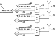
Fig. 4 is the transmitter of the present invention of transmission multiple data signal.
Fig. 5 is a pilot signal receiving circuit of the present invention.
Fig. 6 is a data-signal receiving circuit of the present invention.
Fig. 7 is an embodiment of pilot signal receiving circuit.
Fig. 8 is a minimum average B configuration square weighting circuit.
Fig. 9 is the data-signal receiving circuit that the pilot signal receiving circuit with Fig. 7 uses.
Figure 10 is an embodiment of the pilot signal receiving circuit that is weighted of the output of each RAKE.
Figure 11 is the data-signal receiving circuit that the pilot signal receiving circuit with Figure 10 uses.
Figure 12 is an embodiment of pilot signal receiving circuit, and wherein the antenna of transmission array is closely expansion
Figure 13 is to use the data receiver circuit of the pilot signal receiving circuit of Figure 12.
Figure 14 is the electric wave control in the cdma communication system.
Figure 15 is an electric wave control transmission device.
Figure 16 is the electric wave control transmission device of transmission multiple data signal.
Figure 17 is the data receiver circuit that the transmitter with Figure 14 uses.
Figure 18 is the pilot signal receiving circuit when up link and down link use same frequency
Figure 19 is the transmission circuit that uses with Figure 18.
Figure 20 is the data-signal receiver that the pilot signal receiving circuit with Figure 18 uses.
1: pilot signal
48-52,56-60: antenna
54: data processor
56-60: pilot signal generator
62-66,94,112,162-164,208-212,250-254,302,404,418: combiner
74-78: generator
82-86,100-104,406-410:RAKE88-92,106-110,324-340,344-348,398-402,412-416: weighting device
98,420: the error signal generator
106-110,318-322: flexible strategy device
114-124,178-188,292-294: deferred mount
126,144-160,190-206,214-230,256-260,274-290,304-306,378-382: blender
168,262-266: subtracter
170,268-272,422: flexible strategy adjusting device
174: amplifier 176: integrator
232-248,308-310,424-440: dump (sum and dump) circuit
312-316: electric wave
342: the data-signal generator
392-396: data RAKE weighting
Embodiment
Preferred embodiment is described with reference to the accompanying drawings, and the same numeral in is represented similar elements in full.Fig. 3 is a transmitter of the present invention.This transmitter has an aerial array 48-52, and the preferably is 3 or 4 antennas.For distinguishing the purposes of each antenna 48-52, a different signal produces relevant with each pilot signal generator 56-60.The better signal relevant with each antenna is a pilot signal as shown in figure 13.Each expansion pilot signal is by generation among the pilot signal generator 56-60 that uses a different pseudo-random chip codeword sequence, and by the growth data sequence number combination of combiner 62-66 with each.Each growth data all uses data processor 54 to produce by at blender 378-382 the data-signal that is produced being mixed with the different pseudo-random chip codeword sequence D 1-DN of each antenna 48-52.The signal that is combined is launched to the carrier frequency of wanting and via the antenna 48-52 of array by modulation.
By using array antenna, transmitter usage space difference.If separated must reaching far, the signal of being launched by each antenna 48-52 will be subjected to different multipath distortions when marching to a predetermined receiver.Because will be followed multipath (multipath) to a predetermined receiver by each signal that antenna 48-52 transmits, each received signals will have the multipath composition.These compositions produce the communication port between each antenna 48-52 of transmitter and the receiver.Preferably, when the signal that is transferred to a predetermined receiver by the antenna of 48-52 on an alias road is failed, be used to keep the high SNR of reception from the signal of other antenna of 48-52.This effect is by compatibly reaching at receiver combination received signals.
Fig. 4 is illustrated in and is used in the base station to transmit the transmitter of multiple data signal.Each growth data is by mixing with different pseudo-random chip codeword sequence D 11-DNM and produce from the relative signal of generator 74-78 one at blender 360-376.Make that each data-signal uses the different pseudo-random chip codeword sequence of each antenna 48-52, altogether N * M sign indicating number sequence.N is an antenna amount, and M is the quantity of data-signal.Then, each expanded data signal and the expansion pilot signal combination that is relevant to antenna 48-52.This signal that is combined is by modulation and by the antenna 48-52 of array emission.
The pilot signal receiving circuit is shown in Fig. 5.Each pilot signal that is transmitted is received by antenna 80.To each pilot signal, one removes expanding unit, and a RAKE 82-86 as shown in Figure 5 or a vector correlation device are used to use the duplicating of pseudo-random chip codeword sequence of relative pilot signal, thereby go to expand each pilot signal.This goes expanding unit also to compensate multipath in the communication port.Each pilot signal that is resumed is by a weighting device 88-92 weighting.Flexible strategy refer to the size and the phase place of signal.Be coupled to RAKE though weighting is represented as, weighting device preferably also each of weighting RAKE refer to (finger).After weighting, all pilot signals that are weighted recovery are combined in combiner 94.Use an error signal generator 98, be used to produce error signal by the estimation of the pilot signal that weighted array provided.Based on error signal, the algorithm that is fit to is used in the weighting of each weighting device 88-92, as minimum average B configuration square (least mean squared, LMS) or circulation least square (recursive leastsquares, RLS), be adjusted so that error signal is minimum.Make that the signal quality of the signal that is combined is for maximum.
Fig. 6 represents to use the data-signal receiving circuit of the flexible strategy that determined by the pilot signal restore circuit.The data-signal that is transmitted is recovered by antenna 80.Concerning each antenna 48-52 of transmission array, remove expanding unit from correspondence, as directed RAKE 82-86, be used to by using the employed data-signal of corresponding transmission antenna extended code duplicate the filtering data signal.Use the flexible strategy for each antenna pilot signal decision, each flexible strategy device 106-110 is with the spread signal that goes about the flexible strategy weighting RAKE of corresponding pilot tone.For example, the transmit antenna 48 of weighting device 88 corresponding pilot signals 1.Also be applied to the weighting device 106 of Fig. 6 for the flexible strategy of pilot signal 1 decision by pilot tone RAKE 82.In addition, if the finger of RAKE (finger) is adjusted by the RAKE82-86 of corresponding pilot signal, identical flexible strategy will be applied to the finger (finger) of the RAKE 100-104 of data-signal.After weighting, the signal that is weighted is made up to recover original data-signal by combiner 112.
By data-signal is used the flexible strategy identical with being used for each antenna pilot signal, each RAKE 82-86 compensates the channel distortion by each aerial signal experienced.Make that the data-signal receiving circuit makes the data-signal optimization on each tunnel.By making up the optimization signal of each tunnel best, can increase the signal quality of received signals.
Fig. 7 represents the embodiment of pilot signal restore circuit.Each pilot tone that is transmitted is recovered by receiver antenna 80.Be each pilot tone of de-spread, each RAKE 82-86 uses the pseudo-random chip codeword sequence of corresponding pilot tone, P1-PN.The delay version of each pilot signal is produced by deferred mount 114-124.Each postpones version and mixes with a received signals by a blender 126.This mixed signal passes sum total and dump (sum and dump) circuit 424-440 and uses blender 144-160 to be weighted the quantity that is determined by this flexible strategy adjusting device 170.The multipath composition that is weighted of each pilot tone device 162-164 that is combined makes up.The output of the combination of each pilot tone device 94 that is combined makes up.Because a pilot signal does not have data, the pilot signal that is combined should have a value and be 1+j0.The pilot signal that is combined compares with ideal value 1+j0 at subtracter 168.Based on the pilot signal that is combined, use the algorithm that is fit to adjust by flexible strategy adjusting device 170 from the flexible strategy of the skew weighting device 144-160 of ideal value.
The LMS algorithm that is used to produce flexible strategy is shown in Fig. 8.Thereby the output of subtracter 168 is multiplied by the extended delays version of corresponding pilot tone by using a blender 172.The product of gained will be amplified and be integrated device 176 integrations by an amplifier 174.The result of integration is used to weighting W1M, and RAKE refers to (finger).
The data receiver circuit that uses with the embodiment of Fig. 7 is a base station receiver shown in Figure 9.The signal that is received is transferred into relevant with the antenna 48-52 of each array respectively RAKE 100-104 set.Each RAKE100-104 uses deferred mount 178-188 to produce the employed delay version of received signals.The version that is delayed uses blender 190-206 to be based upon the flexible strategy that pilot tone determined of corresponding antenna and is weighted.The data-signal that is weighted that should be scheduled to RAKE 100-104 is made up by combiner 208-212.One combiner 208-212 is relevant with each N transmit antenna 48-52.Each signal that is combined by blender 214-230 with the signal of combination with mix in order to the extended code that produces M spread data signal D11-DNM at transmitter and quilt is gone to expand M time.Each goes spread data signal through sum total and unloading circuit 232-248.For each data-signal, the corresponding sum total and the result of unloading circuit by a combiner 250-254 combination to recover each data-signal.
Another pilot signal receiving circuit is shown in Figure 10.This receiving circuit go expanded circuit 82-86 identical with Fig. 7.The output of each RAKE 82-86 uses a blender 256-260 to be weighted before going to expand pilot signal in combination.After combination, the pilot signal of combination and ideal value compare, and its comparative result then is used to by using an algorithm that is fit to adjust the flexible strategy of each RAKE output.For adjusting the flexible strategy among each RAKE 82-86, the output of each RAKE 82-86 is used a subtracter 262-266 and an ideal value relatively.Result based on the comparison, the flexible strategy of each weighting device 144-160 are determined by flexible strategy adjusting device 268-272.
The data-signal receiving circuit that uses with the embodiment of Figure 10 is shown in Figure 11.This circuit is similar to the data-signal receiving circuit of Fig. 9 of the blender 274-290 of the output of having added each sum total of weighting and unloading circuit 232-248.The amount that each sum total and unloading circuit 232-248 are weighted is identical with the amount that corresponding pilot tone RAKE 82-86 is weighted.Preferably, the output of each RAKE combiner 208-212 can be weighted the amount of corresponding pilot tone RAKE 82-86 to replace mixed flexible strategy before mixed device 214-230 mixes.
If the interval of the antenna 48-52 in the transmission array is little, the signal of each antenna will experience similar multi-path environment.The pilot reception circuit of Figure 12 can be used in this case.The flexible strategy of selected pilot signal are determined in the mode that is similar to Figure 10.Yet because the transmission of each pilot tone through identical tunnel, is the simplification circuit, identical flexible strategy are used to expand other pilot signal.Deferred mount 292-294 produces the delay version of received signals.It is identical with the flexible strategy that version was weighted of the delay of corresponding selected pilot signal by a blender 296-230 weighting that each is delayed version.The output of weighting device is made up by a combiner 302.The signal that is combined uses the quilt that duplicates of the pseudo-random chip codeword sequence P2-Pn of pilot signal to be gone expansion by blender 304-306.The blender 304-306 of each pilot tone passes sum total and unloading circuit 308-310.Identical with the mode of Figure 10, each pilot tone of being gone to expand is weighted and makes up.
The data-signal restore circuit that uses with the embodiment of Figure 12 is shown in Figure 13.Deferred mount 178-180 produces the delay version of received signals.Each is delayed the mixed device 190-194 of version and is weighted in the employed identical flexible strategy of pilot signal among the 12 figure.The output of the blender device 208 that is combined makes up.The output of combiner 208 is transfused to each data-signal despreader of Figure 13.
The present invention also provides the technology of adaptability electric wave control as shown in figure 14.To in pattern, produce structural and destructive interference based on the flexible strategy of each the antenna 48-52 that is provided for array by each signal that aerial array transmitted.Make that by the flexible strategy of selecting to be fit to, the electric wave 312-316 of aerial array is directed to desirable direction.
Figure 15 represents electric wave control transfer circuit.The circuit with extra flexible strategy device 318-322 of this circuit and Fig. 3 is similar.The target receiver will receive the pilot signal of being transmitted by array.Use the pilot signal receiving circuit of Fig. 5, the flexible strategy of the RAKE output of each pilot tone are adjusted in the decision of target receiver.These flexible strategy also are sent to transmitter, as passing through to use signalling channel.These flexible strategy are transfused to spread data signal as shown in Figure 5.For each antenna, spread data signal gives flexible strategy by weighting device 318-322, and this weighting device correspondence is used to be adjusted at the flexible strategy of the antenna pilot signal on the target receiver that the expansion gain is provided.Make that the data-signal that is launched will be focused to this target receiver.Figure 16 represents electric wave control transmission device, is used to transmit the base station of multiple data signal to the different target receiver.The flexible strategy that received by the target receiver are applied to corresponding data-signal by weighting device 324-340.
Figure 17 represents the signal receiving circuit of the electric wave control transmission device of Figure 15 and Figure 16.Because the signal that is transmitted is weighted, the data-signal receiving circuit does not need the weighting device 106-110 of Fig. 6.
The advantage of electric wave control of the present invention is dual.The signal that is transmitted is assembled by the head for target receiver, has improved the quality of received signals.On the contrary, this signal departs from other receiver and is assembled, and has reduced the interference to other signal.Because this two factor uses the capacity of the system of electric wave control of the present invention to increase.Make that because the employed suitable algorithm of pilot signal receiving circuit, flexible strategy can be adjusted to dynamic.By adjusting flexible strategy, the electric wave of data-signal will dynamically respond mobile receiver or transmitter and the change of response in multi-path environment.
In the system of the same frequency that uses down link and uplink signal, (timedivision duplex, TDD), another embodiment is used duplex when for example drawing.Because toward renaturation, the down link signal experience is as the multipath of the uplink signal that transmits on same frequency.For obtaining reciprocal advantage, be used to the transmitter of base station by the flexible strategy that receiver determined of base station.In this system, the receiving circuit of Figure 18 base station is to put altogether with the transmission circuit of Figure 19, as in a base station.
In the receiving circuit of Figure 18, each antenna 48-52 receives each pilot signal by UE transmitted.Each pilot tone is filtered by RAKE 406-410 and by a weighting device 412-416 weighting.The pilot signal that is weighted and filters device 418 combination that is combined.Use error signal generator 420 and flexible strategy adjusting device 422, the flexible strategy relevant with flexible strategy device 412-416 are used the algorithm that is fit to and are adjusted.
The transmission circuit of Figure 19 has a data-signal generator 342 to produce a data-signal.Data-signal uses blender 384 to be expanded.The data-signal that is expanded is weighted device 344-348 weighting, as by the weighting for each tunnel decision of the receiving circuit of Figure 19.
The circuit of Figure 20 is in order to the data-signal receiving circuit as the base station.Data signals transmitted is received by multiple antenna 48-52.One data RAKE 392-396 is coupled to each antenna 48-52 with the filtering data signal.The data-signal that is filtered is weighted the flexible strategy that reception pilot tone that device 398-402 is weighted to corresponding antenna is determined, and is combined with the restore data signal at combiner 404.Because the data-signal that the transmission circuit of Figure 19 transmission has best flexible strategy, will be in the signal quality of the data-signal that is resumed of EU than the quality height of the signal that known technology provided.
Claims (19)
1. an exhibition that is used for having a plurality of transmit antennas (48-52) on the single position method of communication system frequently is characterized in that:
The pilot signal that has unique pseudo-random chip codeword sequence relevant from each transmit antenna (48-52) transmission with this antenna (48-52);
Receive whole described pilot signals that is transmitted at this receiver;
Use each this pilot signal that is transmitted of pseudo-random chip codeword sequence filter of this pilot signal;
With a flexible strategy weighting this pilot signal that is filtered respectively;
Making up the described pilot signal that is weighted is a composite signal;
Use the flexible strategy of adjusting each this pilot signal in the adaptive algorithm of signal quality of this composite signal one;
Transmit a data-signal, make the different exhibition frequency version of data-signal be transmitted from each antenna (48-52), each exhibition version frequently has different chip codewords with regard to the associated transport antenna; And
Each exhibition that has its relevant chip codeword via filtration is version and received signal and make up the described version that is filtered frequently, and wherein different exhibitions versions frequently are weighted by the use flexible strategy that are adjusted relevant with the pilot signal of each antenna (48-52).
2. the method for claim 1 is characterized in that, the exhibition of this difference frequently version before transmission by using controlled flexible strategy to be weighted.
3. the method for claim 1 is characterized in that, this difference exhibition version frequently receives afterwards by using controlled flexible strategy to be weighted.
4. the method for claim 1 is characterized in that, this adaptive algorithm is an a minimum average B configuration square algorithm.
5. the method for claim 1 is characterized in that, this adaptive algorithm is a circulation least square algorithm.
6 the method for claim 1 is characterized in that, this filtration and weighting step take place simultaneously.
7. the method for claim 1 is characterized in that, each this be transmitted pilot signal and this data-signal each exhibition filtration of version frequently (82-86 100-104) carries out by a RAKE.
8. the method for claim 1 is characterized in that, each this each exhibition filtration of version frequently that is transmitted pilot signal and this data-signal is carried out by the expansion of a vector correlation device.
9. method as claimed in claim 7, it is characterized in that, the weighting of each this pilot signal is by referring to (finger) (144-148 to each of the RAKE (82-86) of this pilot tone, 150-154,156-160) weighting one flexible strategy and getting, and each this exhibition of the RAKE of data-signal frequently each of version refer to (finger) (190-194,196-200,202-286, weighting 274-290) refers to (finger) (144-148 by using with each of this pilot signal RAKE (82-86) of the pilot signal of each antenna (48-52), 150-154, each 156-160) relevant flexible strategy are weighted and realize.
10. method as claimed in claim 7, it is characterized in that, each of the RAKE (82-86) of the weighting of each this pilot signal by this pilot tone of weighting refers to (finger) (144-148,150-154,156-160) and the RAKE of this pilot tone of weighting (82-86) one output, and each this exhibition of this data-signal weighting of version is frequently exported the relevant flexible strategy that are adjusted with one of the pilot signal RAKE (82-86) of each antenna (48-52) and is come weighting each refers to (finger) (190-194 by using, 196-200,202-286,274-290) and each this exhibition of data-signal RAKE (100-104) frequently version this output and realize.
11. an exhibition frequency communication system is characterized in that:
One at single locational transmitter, comprising:
A plurality of transmit antennas (48-52);
One pilot transmission device (56-60) is in order to have the pilot signal of unique pseudo-random chip codeword sequence relevant with this antenna (48-52) from each transmit antenna (48-52) transmission; And
(378-382 360-376), in order to transmit a data-signal, makes the difference exhibition frequency version of this data-signal be transmitted from each transmit antenna to one data device, and each exhibition version frequently has the different chip codewords that are used for each transmit antenna; And
One receiver comprises:
One reception antenna (80);
One filter (82-86 88-92), is coupled to this reception antenna each this signal that is transmitted of pseudo-random chip codeword sequence filter in order to use this pilot signal, and with each pilot signal that is filtered of a flexible strategy weighting;
One composite set (94) is a composite signal in order to make up the described pilot signal that is weighted;
One adjusting device (98) is in order to the specific flexible strategy of adjustment based on each this pilot signal of an adaptive algorithm of a signal quality of this composite signal of use; And
One receiving system (100-104,106-110,112), receive data-signal in order to each the exhibition frequency version that has its related chip sign indicating number via filtration, and make up the described version that is filtered, wherein different exhibition version frequently comes weighting by using controlled flexible strategy relevant with the pilot signal of each antenna (48-52).
12. system as claimed in claim 11 is characterized in that, this transmitter also comprises a weighting device, in order to the different exhibition frequency version of weighting by using these controlled flexible strategy.
13. system as claimed in claim 11 is characterized in that, this receiver also comprises a weighting device (82-86), in order to the different exhibition frequency version of weighting by using these controlled flexible strategy.
14. system as claimed in claim 11 is characterized in that, this adjusting device (98) uses a minimum average B configuration square algorithm to adjust the specific flexible strategy of each this pilot signal.
15. system as claimed in claim 11 is characterized in that, this adjusting device (98) uses a circulation least square algorithm to adjust the specific flexible strategy of this pilot signal.
16. system as claimed in claim 11, it is characterized in that, this filter (82-86,88-92) comprise a plurality of RAKE (82-86) so that filter each this pilot signal that is transmitted respectively, and this receiving system (100-104,106-110,112) comprise a plurality of RAKE (100-104) so that filter each exhibition frequency version of this data-signal respectively.
17. system as claimed in claim 11, it is characterized in that, this filter (82-86,88-92) comprise a plurality of vector correlation devices so that expand each this pilot signal that is transmitted respectively, and this receiving system (100-104,106-110,112) comprise a plurality of vector correlation devices so that expand each exhibition frequency version of this data-signal respectively.
18. system as claimed in claim 16, it is characterized in that, this filter (82-86,88-92) by referring to (finger) (144-148 with each of this pilot tone of flexible strategy weighting RAKE (82-86), 150-154,156-160) and this pilot signal of weighting, and each this exhibition of data-signal RAKE (100-104) frequently each of version refer to (finger) (190-194,196-200,202-286, each refers to that (finger) (156-160) the relevant flexible strategy that are adjusted are weighted and realize for 144-148,150-154 with this pilot signal RAKE (82-86) of the pilot signal of each antenna (48-52) by using in weighting 274-290).
19. system as claimed in claim 16, it is characterized in that, this filter (82-86) is by each specific finger (finger) (144-148 of this pilot tone of weighting RAKE (82-86), 150-154,156-160) and this pilot tone of weighting RAKE (82-86) one output and each pilot signal of weighting, and each this exhibition of this data-signal output and the finger (144-148 respectively of the RAKE (82-86) of the pilot signal of weighting by utilizing each antenna (48-52) of version frequently, 150-154,156-160) the relevant flexible strategy that are adjusted are come weighting each are referred to (finger) (190-194,196-200,202-286,274-290) and each exhibition of described data-signal RAKE (100-104) frequently version this output and realize.
Applications Claiming Priority (2)
| Application Number | Priority Date | Filing Date | Title |
|---|---|---|---|
| US09/394,452 | 1999-09-10 | ||
| US09/394,452 US6115406A (en) | 1999-09-10 | 1999-09-10 | Transmission using an antenna array in a CDMA communication system |
Related Child Applications (4)
| Application Number | Title | Priority Date | Filing Date |
|---|---|---|---|
| CN2006101007770A Division CN1897483B (en) | 1999-09-10 | 2000-08-17 | Transmission using an antenna array in a CDMA communication system |
| CN2006101007766A Division CN1897482B (en) | 1999-09-10 | 2000-08-17 | Transmission using an antenna array in a CDMA communication system |
| CN2006101003093A Division CN1881832B (en) | 1999-09-10 | 2000-08-17 | Transmission using an antenna array in a CDMA communication system |
| CNA2005101250062A Division CN1770657A (en) | 1999-09-10 | 2000-08-17 | Base station for use in a CDMA communication system using an antenna array |
Publications (2)
| Publication Number | Publication Date |
|---|---|
| CN1373941A CN1373941A (en) | 2002-10-09 |
| CN1237737C true CN1237737C (en) | 2006-01-18 |
Family
ID=23559015
Family Applications (5)
| Application Number | Title | Priority Date | Filing Date |
|---|---|---|---|
| CNB008126372A Expired - Fee Related CN1237737C (en) | 1999-09-10 | 2000-08-17 | Transmission using antenna array in CDMA communication system |
| CN2006101003093A Expired - Lifetime CN1881832B (en) | 1999-09-10 | 2000-08-17 | Transmission using an antenna array in a CDMA communication system |
| CNA2005101250062A Pending CN1770657A (en) | 1999-09-10 | 2000-08-17 | Base station for use in a CDMA communication system using an antenna array |
| CN2006101007766A Expired - Lifetime CN1897482B (en) | 1999-09-10 | 2000-08-17 | Transmission using an antenna array in a CDMA communication system |
| CN2006101007770A Expired - Lifetime CN1897483B (en) | 1999-09-10 | 2000-08-17 | Transmission using an antenna array in a CDMA communication system |
Family Applications After (4)
| Application Number | Title | Priority Date | Filing Date |
|---|---|---|---|
| CN2006101003093A Expired - Lifetime CN1881832B (en) | 1999-09-10 | 2000-08-17 | Transmission using an antenna array in a CDMA communication system |
| CNA2005101250062A Pending CN1770657A (en) | 1999-09-10 | 2000-08-17 | Base station for use in a CDMA communication system using an antenna array |
| CN2006101007766A Expired - Lifetime CN1897482B (en) | 1999-09-10 | 2000-08-17 | Transmission using an antenna array in a CDMA communication system |
| CN2006101007770A Expired - Lifetime CN1897483B (en) | 1999-09-10 | 2000-08-17 | Transmission using an antenna array in a CDMA communication system |
Country Status (18)
| Country | Link |
|---|---|
| US (8) | US6115406A (en) |
| EP (7) | EP1447924B1 (en) |
| JP (5) | JP3767893B2 (en) |
| KR (1) | KR100451807B1 (en) |
| CN (5) | CN1237737C (en) |
| AT (4) | ATE465561T1 (en) |
| AU (2) | AU761473B2 (en) |
| BR (1) | BR0013889A (en) |
| CA (3) | CA2498521C (en) |
| DE (6) | DE1210777T1 (en) |
| DK (4) | DK1447924T3 (en) |
| ES (4) | ES2225197T3 (en) |
| HK (7) | HK1045611B (en) |
| IL (4) | IL148412A0 (en) |
| MX (1) | MXPA02002522A (en) |
| NO (4) | NO327636B1 (en) |
| PT (1) | PT1210777E (en) |
| WO (2) | WO2001018993A1 (en) |
Families Citing this family (83)
| Publication number | Priority date | Publication date | Assignee | Title |
|---|---|---|---|---|
| US6792290B2 (en) * | 1998-09-21 | 2004-09-14 | Ipr Licensing, Inc. | Method and apparatus for performing directional re-scan of an adaptive antenna |
| US6128330A (en) | 1998-11-24 | 2000-10-03 | Linex Technology, Inc. | Efficient shadow reduction antenna system for spread spectrum |
| US6597669B1 (en) * | 1999-03-16 | 2003-07-22 | Northrop Grumman Corporation | Queue segmentation and addressing method and apparatus for a cell switch in a processing communications satellite |
| US6765969B1 (en) * | 1999-09-01 | 2004-07-20 | Motorola, Inc. | Method and device for multi-user channel estimation |
| US6278726B1 (en) * | 1999-09-10 | 2001-08-21 | Interdigital Technology Corporation | Interference cancellation in a spread spectrum communication system |
| US6115406A (en) * | 1999-09-10 | 2000-09-05 | Interdigital Technology Corporation | Transmission using an antenna array in a CDMA communication system |
| US6597730B1 (en) * | 1999-11-03 | 2003-07-22 | Northrop Grumman Corporation | Satellite communication array transceiver |
| US20010033600A1 (en) * | 2000-02-28 | 2001-10-25 | Golden Bridge Technology Inc. | Sectorized smart antenna system and method |
| US7965794B2 (en) * | 2000-05-05 | 2011-06-21 | Greenwich Technologies Associates | Method and apparatus for broadcasting with spatially diverse signals |
| US6434366B1 (en) * | 2000-05-31 | 2002-08-13 | Motorola, Inc. | Method and system for estimating adaptive array weights used to transmit a signal to a receiver in a wireless communication system |
| US8363744B2 (en) | 2001-06-10 | 2013-01-29 | Aloft Media, Llc | Method and system for robust, secure, and high-efficiency voice and packet transmission over ad-hoc, mesh, and MIMO communication networks |
| US6870825B1 (en) * | 2000-09-06 | 2005-03-22 | Lucent Technologies Inc. | Pilot signal transmission in a multi-transmit antenna wireless communication system |
| FR2814014B1 (en) * | 2000-09-14 | 2002-10-11 | Mitsubishi Electric Inf Tech | MULTI-USER DETECTION METHOD |
| WO2002032017A1 (en) * | 2000-10-11 | 2002-04-18 | Samsung Electronics Co., Ltd. | Apparatus and method for controlling transmit antenna array for physical downlink shared channel in a mobile communication system |
| US20020110108A1 (en) * | 2000-12-07 | 2002-08-15 | Younglok Kim | Simple block space time transmit diversity using multiple spreading codes |
| JP2002198875A (en) * | 2000-12-22 | 2002-07-12 | Nippon Soken Inc | Communication terminal of cdma system |
| US20020131386A1 (en) * | 2001-01-26 | 2002-09-19 | Docomo Communications Laboratories Usa, Inc. | Mobility prediction in wireless, mobile access digital networks |
| GB2398975B (en) * | 2001-02-01 | 2005-02-23 | Fujitsu Ltd | Communications systems |
| KR100424537B1 (en) * | 2001-04-18 | 2004-03-27 | 엘지전자 주식회사 | Method for beamforming using smart antenna array |
| US6810236B2 (en) | 2001-05-14 | 2004-10-26 | Interdigital Technology Corporation | Dynamic channel quality measurement procedure for adaptive modulation and coding techniques |
| US7170924B2 (en) * | 2001-05-17 | 2007-01-30 | Qualcomm, Inc. | System and method for adjusting combiner weights using an adaptive algorithm in wireless communications system |
| US6990137B2 (en) * | 2001-05-17 | 2006-01-24 | Qualcomm, Incorporated | System and method for received signal prediction in wireless communications systems |
| US7548506B2 (en) * | 2001-10-17 | 2009-06-16 | Nortel Networks Limited | System access and synchronization methods for MIMO OFDM communications systems and physical layer packet and preamble design |
| US7218684B2 (en) * | 2001-11-02 | 2007-05-15 | Interdigital Technology Corporation | Method and system for code reuse and capacity enhancement using null steering |
| US7099380B1 (en) | 2001-11-16 | 2006-08-29 | Marvell International Ltd. | Apparatus for antenna diversity for wireless communication and method thereof |
| US7133461B2 (en) * | 2001-12-14 | 2006-11-07 | Motorola, Inc. | Stream transmission method and device |
| JP3642483B2 (en) * | 2002-01-09 | 2005-04-27 | 日本電気株式会社 | Wireless mobile station and wireless communication system including the same |
| US20030171834A1 (en) * | 2002-03-07 | 2003-09-11 | Silvester Kelan C. | Method and apparatus for connecting a portable media player wirelessly to an automobile entertainment system |
| US8194770B2 (en) | 2002-08-27 | 2012-06-05 | Qualcomm Incorporated | Coded MIMO systems with selective channel inversion applied per eigenmode |
| US7292622B2 (en) * | 2002-10-08 | 2007-11-06 | Freescale Semiconductor, Inc. | Method and apparatus for raking in a wireless network |
| US7986742B2 (en) * | 2002-10-25 | 2011-07-26 | Qualcomm Incorporated | Pilots for MIMO communication system |
| US8169944B2 (en) | 2002-10-25 | 2012-05-01 | Qualcomm Incorporated | Random access for wireless multiple-access communication systems |
| US8170513B2 (en) | 2002-10-25 | 2012-05-01 | Qualcomm Incorporated | Data detection and demodulation for wireless communication systems |
| US7324429B2 (en) | 2002-10-25 | 2008-01-29 | Qualcomm, Incorporated | Multi-mode terminal in a wireless MIMO system |
| US8218609B2 (en) | 2002-10-25 | 2012-07-10 | Qualcomm Incorporated | Closed-loop rate control for a multi-channel communication system |
| US8134976B2 (en) | 2002-10-25 | 2012-03-13 | Qualcomm Incorporated | Channel calibration for a time division duplexed communication system |
| US8570988B2 (en) | 2002-10-25 | 2013-10-29 | Qualcomm Incorporated | Channel calibration for a time division duplexed communication system |
| US20040081131A1 (en) | 2002-10-25 | 2004-04-29 | Walton Jay Rod | OFDM communication system with multiple OFDM symbol sizes |
| CN101242214B (en) * | 2002-10-25 | 2012-09-05 | 高通股份有限公司 | Method for generating pilots for MIMO communication systems |
| US7002900B2 (en) | 2002-10-25 | 2006-02-21 | Qualcomm Incorporated | Transmit diversity processing for a multi-antenna communication system |
| US8320301B2 (en) | 2002-10-25 | 2012-11-27 | Qualcomm Incorporated | MIMO WLAN system |
| US8208364B2 (en) * | 2002-10-25 | 2012-06-26 | Qualcomm Incorporated | MIMO system with multiple spatial multiplexing modes |
| CN1717901A (en) * | 2002-10-25 | 2006-01-04 | 高通股份有限公司 | Random access for wireless multiple-access communication systems |
| JP4226442B2 (en) * | 2002-11-14 | 2009-02-18 | パナソニック株式会社 | Wireless communication device |
| JP3583414B2 (en) * | 2002-11-14 | 2004-11-04 | 松下電器産業株式会社 | CDMA transmitting apparatus and CDMA receiving apparatus |
| JP4090331B2 (en) * | 2002-11-20 | 2008-05-28 | 三洋電機株式会社 | Reception method and apparatus |
| JP4163971B2 (en) * | 2003-02-06 | 2008-10-08 | 松下電器産業株式会社 | Transmitting apparatus and transmitting method |
| US7155177B2 (en) * | 2003-02-10 | 2006-12-26 | Qualcomm Incorporated | Weight prediction for closed-loop mode transmit diversity |
| US7301990B2 (en) * | 2003-02-21 | 2007-11-27 | Qualcomm Incorporated | Equalization of multiple signals received for soft handoff in wireless communication systems |
| US7983355B2 (en) * | 2003-07-09 | 2011-07-19 | Broadcom Corporation | System and method for RF signal combining and adaptive bit loading for data rate maximization in multi-antenna communication systems |
| US8391322B2 (en) | 2003-07-09 | 2013-03-05 | Broadcom Corporation | Method and system for single weight (SW) antenna system for spatial multiplexing (SM) MIMO system for WCDMA/HSDPA |
| US9473269B2 (en) | 2003-12-01 | 2016-10-18 | Qualcomm Incorporated | Method and apparatus for providing an efficient control channel structure in a wireless communication system |
| DE10359268B4 (en) * | 2003-12-17 | 2011-05-19 | Infineon Technologies Ag | Device for generating transmission signals in a mobile radio station by means of a scrambling code generator for preambles and for transmission signals of dedicated physical channels |
| CA2558543A1 (en) * | 2004-03-05 | 2005-09-22 | Qualcomm Incorporated | Multi-antenna receive diversity control in wireless communications |
| CN1943134B (en) * | 2004-03-05 | 2011-08-24 | 高通股份有限公司 | Multi-antenna receive diversity control in wireless communications |
| CN1300949C (en) * | 2004-06-07 | 2007-02-14 | 东南大学 | Parallelling receiving method by chip balancer and rake receiver |
| US8503328B2 (en) | 2004-09-01 | 2013-08-06 | Qualcomm Incorporated | Methods and apparatus for transmission of configuration information in a wireless communication network |
| US7593493B2 (en) * | 2004-10-06 | 2009-09-22 | Broadcom Corporation | Method and system for pre-equalization in a single weight (SW) single channel (SC) multiple-input multiple-output (MIMO) system |
| US8009772B1 (en) | 2004-11-04 | 2011-08-30 | Sandia Corporation | Concurrent signal combining and channel estimation in digital communications |
| FR2877776B1 (en) * | 2004-11-05 | 2007-01-26 | Thales Sa | HIGH ENERGY LASER AMPLIFICATION DEVICE WITH HIGH BEAM QUALITY |
| DE602005013000D1 (en) * | 2005-02-07 | 2009-04-09 | Ericsson Telefon Ab L M | TRANSFER RATE MEASUREMENTS |
| US7610025B2 (en) | 2005-03-29 | 2009-10-27 | Qualcomm Incorporated | Antenna array pattern distortion mitigation |
| US7466749B2 (en) | 2005-05-12 | 2008-12-16 | Qualcomm Incorporated | Rate selection with margin sharing |
| US8358714B2 (en) | 2005-06-16 | 2013-01-22 | Qualcomm Incorporated | Coding and modulation for multiple data streams in a communication system |
| KR100981495B1 (en) * | 2005-10-12 | 2010-09-10 | 삼성전자주식회사 | Method and apparatus for transmitting data in a communication system |
| US8107549B2 (en) | 2005-11-30 | 2012-01-31 | Qualcomm, Incorporated | Multi-stage receiver for wireless communication |
| US20070297497A1 (en) * | 2006-06-21 | 2007-12-27 | Seibert Cristina A | Apparatus And Method For Interference Cancellation |
| CN101098218B (en) * | 2006-06-27 | 2011-11-30 | 中兴通讯股份有限公司 | Transmitter and receiver of arbitrary access front signal |
| JP2008085921A (en) * | 2006-09-28 | 2008-04-10 | Matsushita Electric Ind Co Ltd | Radio transmission apparatus and radio receiving apparatus |
| JP4936027B2 (en) * | 2007-04-05 | 2012-05-23 | 日本電気株式会社 | Time reference identification method |
| WO2008126516A1 (en) * | 2007-04-10 | 2008-10-23 | Naoki Suehiro | Transmitting method, transmitting device, receiving method, and receiving device |
| US8902831B2 (en) * | 2008-06-17 | 2014-12-02 | Centre Of Excellence In Wireless Technology | Methods and systems for interference mitigation |
| US8155138B2 (en) * | 2008-08-19 | 2012-04-10 | Qualcomm Incorporated | Training sequences for very high throughput wireless communication |
| US8767524B2 (en) * | 2008-08-19 | 2014-07-01 | Qualcomm Incorporated | Training sequences for very high throughput wireless communication |
| CN103004273A (en) * | 2010-07-16 | 2013-03-27 | 京瓷株式会社 | Wireless base station and communications control method |
| CN102412881B (en) * | 2010-09-26 | 2015-06-17 | 日电(中国)有限公司 | Wireless communication system and beamforming training method applied to wireless communication system |
| WO2012104828A1 (en) * | 2011-02-03 | 2012-08-09 | Dsp Group Ltd. | A method and apparatus for hierarchical adaptive filtering |
| US10285186B2 (en) | 2012-06-29 | 2019-05-07 | Huawei Technologies Co., Ltd. | System and method for grouping and selecting transmission points |
| KR20170113536A (en) | 2014-11-17 | 2017-10-12 | 혁 엠. 권 | Spreading sequence system for full connectivity relay network |
| US10601539B2 (en) | 2018-02-02 | 2020-03-24 | J3 Technology LLC | Multiple jamming signal transmit antennas with spatial diversity |
| CN108494459B (en) * | 2018-03-02 | 2021-10-26 | Oppo广东移动通信有限公司 | Antenna switching method, device, storage medium and mobile terminal |
| RU2688920C1 (en) * | 2018-08-28 | 2019-05-23 | Общество с ограниченной ответственностью "КАСКАД" | Apparatus and method for radio communication based on simo-ofdm technology |
| US20230093484A1 (en) * | 2021-09-23 | 2023-03-23 | Apple Inc. | Systems and methods for de-correlating coded signals in dual port transmissions |
Family Cites Families (111)
| Publication number | Priority date | Publication date | Assignee | Title |
|---|---|---|---|---|
| US3662268A (en) * | 1970-11-17 | 1972-05-09 | Bell Telephone Labor Inc | Diversity communication system using distinct spectral arrangements for each branch |
| US4901307A (en) * | 1986-10-17 | 1990-02-13 | Qualcomm, Inc. | Spread spectrum multiple access communication system using satellite or terrestrial repeaters |
| US4736460A (en) * | 1986-11-10 | 1988-04-05 | Kenneth Rilling | Multipath reduction system |
| JPH0758971B2 (en) * | 1989-09-07 | 1995-06-21 | 株式会社東芝 | Communication control device |
| JP2795935B2 (en) * | 1989-11-24 | 1998-09-10 | 三菱電機株式会社 | Maximum likelihood sequence estimator |
| US5381344A (en) * | 1992-04-06 | 1995-01-10 | Hewlett-Packard Company | Apparatus and method for obtaining a list of numbers of wafers for integrated circuit testing |
| US5319677A (en) * | 1992-05-12 | 1994-06-07 | Hughes Aircraft Company | Diversity combiner with MLSE for digital cellular radio |
| US5331666A (en) | 1992-06-08 | 1994-07-19 | Ericsson Ge Mobile Communications Inc. | Adaptive maximum likelihood demodulator |
| US5796779A (en) * | 1992-06-29 | 1998-08-18 | Raytheon Company | Adaptive signal processor for non-stationary environments and method |
| US5712868A (en) | 1992-06-30 | 1998-01-27 | Motorola, Inc. | Dual mode communication network |
| US5381443A (en) * | 1992-10-02 | 1995-01-10 | Motorola Inc. | Method and apparatus for frequency hopping a signalling channel in a communication system |
| US5812542A (en) | 1996-03-18 | 1998-09-22 | Motorola, Inc. | Method for determining weighting coefficients in a CDMA radio receiver |
| US5457704A (en) * | 1993-05-21 | 1995-10-10 | At&T Ipm Corp. | Post processing method and apparatus for symbol reliability generation |
| US5493563A (en) * | 1993-07-26 | 1996-02-20 | Motorola, Inc. | Method and apparatus for mobile assisted handoff in a communication system |
| GB9315845D0 (en) | 1993-07-30 | 1993-09-15 | Roke Manor Research | Apparatus for use in equipment providing a digital radio link between a fixed and a mobile radio unit |
| JP3560991B2 (en) * | 1993-09-20 | 2004-09-02 | 株式会社東芝 | Adaptive maximum likelihood sequence estimator |
| WO1995010924A1 (en) * | 1993-10-12 | 1995-04-20 | Ntt Mobile Communications Network Inc. | Multistation transmitting method and receiver therefor |
| US5790606A (en) * | 1994-01-11 | 1998-08-04 | Ericsson Inc. | Joint demodulation using spatial maximum likelihood |
| US5559789A (en) * | 1994-01-31 | 1996-09-24 | Matsushita Electric Industrial Co., Ltd. | CDMA/TDD Radio Communication System |
| US5455413A (en) | 1994-03-31 | 1995-10-03 | Thomson Consumer Electronics, Inc. | Mechanism for retaining an electronically readable card in an electronic device |
| WO1995034140A1 (en) | 1994-06-03 | 1995-12-14 | Motorola, Inc. | Method and apparatus for cancelling interference in signals having undergone multipath |
| WO1996000471A1 (en) * | 1994-06-23 | 1996-01-04 | Ntt Mobile Communications Network Inc. | Cdma demodulation circuit and demodulating method |
| US6081566A (en) * | 1994-08-02 | 2000-06-27 | Ericsson, Inc. | Method and apparatus for interference rejection with different beams, polarizations, and phase references |
| US5680419A (en) * | 1994-08-02 | 1997-10-21 | Ericsson Inc. | Method of and apparatus for interference rejection combining in multi-antenna digital cellular communications systems |
| US5623511A (en) | 1994-08-30 | 1997-04-22 | Lucent Technologies Inc. | Spread spectrum code pulse position modulated receiver having delay spread compensation |
| FI102797B (en) | 1994-10-07 | 1999-02-15 | Nokia Mobile Phones Ltd | A method of signal detection in a receiver of a TDMA mobile communication system, and a receiver implementing the method |
| US5574747A (en) * | 1995-01-04 | 1996-11-12 | Interdigital Technology Corporation | Spread spectrum adaptive power control system and method |
| JPH08195703A (en) * | 1995-01-17 | 1996-07-30 | Toshiba Corp | Radio communication equipment |
| US5822701A (en) * | 1995-02-27 | 1998-10-13 | Ntt Mobile Communications Network Inc. | High-speed radio communication system |
| ZA965340B (en) * | 1995-06-30 | 1997-01-27 | Interdigital Tech Corp | Code division multiple access (cdma) communication system |
| DE69637911D1 (en) * | 1995-07-19 | 2009-06-04 | Nec Corp | Code diversity diversity diversity transmission system |
| JP2762965B2 (en) * | 1995-09-04 | 1998-06-11 | 日本電気株式会社 | Base station transmission power control method |
| US5734646A (en) * | 1995-10-05 | 1998-03-31 | Lucent Technologies Inc. | Code division multiple access system providing load and interference based demand assignment service to users |
| US5903834A (en) * | 1995-10-06 | 1999-05-11 | Telefonaktiebolaget L/M Ericsson | Distributed indoor digital multiple-access cellular telephone system |
| US6069912A (en) * | 1995-11-29 | 2000-05-30 | Ntt Mobile Communications Network, Inc. | Diversity receiver and its control method |
| JP2934185B2 (en) * | 1996-03-15 | 1999-08-16 | 松下電器産業株式会社 | CDMA cellular radio base station apparatus, mobile station apparatus, and transmission method |
| US5809020A (en) | 1996-03-18 | 1998-09-15 | Motorola, Inc. | Method for adaptively adjusting weighting coefficients in a cDMA radio receiver |
| US5757791A (en) * | 1996-04-18 | 1998-05-26 | American Wireless Technology, Inc. | Multistage linear receiver for DS-CDMA systems |
| DE69705356T2 (en) * | 1996-05-17 | 2002-05-02 | Motorola Ltd | Method and device for weighting a transmission path |
| FR2751499B1 (en) * | 1996-07-16 | 1998-08-28 | Duponteil Daniel | DIGITAL DIFFERENTIAL DEMODULATION METHOD |
| JP2798127B2 (en) * | 1996-07-19 | 1998-09-17 | 日本電気株式会社 | Transmission device and communication device including the same |
| KR0173911B1 (en) * | 1996-07-25 | 1999-04-01 | 에스케이텔레콤주식회사 | Communication system using cdma modulating demodulating mathod reducing interference |
| US5822380A (en) * | 1996-08-12 | 1998-10-13 | Ericsson Inc. | Apparatus and method for joint channel estimation |
| JP3720141B2 (en) * | 1996-10-01 | 2005-11-24 | 松下電器産業株式会社 | Mobile communication method and apparatus |
| US5889827A (en) * | 1996-12-12 | 1999-03-30 | Ericsson Inc. | Method and apparatus for digital symbol detection using medium response estimates |
| US6335954B1 (en) * | 1996-12-27 | 2002-01-01 | Ericsson Inc. | Method and apparatus for joint synchronization of multiple receive channels |
| US6026130A (en) * | 1997-03-04 | 2000-02-15 | Advanced Micro Devices, Inc. | System and method for estimating a set of parameters for a transmission channel in a communication system |
| US6161209A (en) * | 1997-03-28 | 2000-12-12 | Her Majesty The Queen In Right Of Canada, As Represented By The Minister Of Industry Through The Communications Research Centre | Joint detector for multiple coded digital signals |
| US6044120A (en) * | 1997-05-01 | 2000-03-28 | Lucent Technologies Inc. | Time-varying weight estimation |
| US6147985A (en) * | 1997-05-01 | 2000-11-14 | Lucent Technologies Inc. | Subspace method for adaptive array weight tracking |
| JP3058261B2 (en) * | 1997-05-28 | 2000-07-04 | 日本電気株式会社 | CDMA handoff system, mobile communication cellular system using the same, and base station thereof |
| JPH10336144A (en) | 1997-05-29 | 1998-12-18 | Matsushita Electric Ind Co Ltd | Code division multiple access mobile communication device |
| JP3985299B2 (en) | 1997-07-14 | 2007-10-03 | 三菱電機株式会社 | Mobile communication system |
| US6333953B1 (en) | 1997-07-21 | 2001-12-25 | Ericsson Inc. | System and methods for selecting an appropriate detection technique in a radiocommunication system |
| US6215762B1 (en) * | 1997-07-22 | 2001-04-10 | Ericsson Inc. | Communication system and method with orthogonal block encoding |
| US6108517A (en) * | 1997-07-28 | 2000-08-22 | Ericsson Inc. | Methods and apparatus for joint demodulation of adjacent channel signals in digital communications systems |
| KR19990016606A (en) | 1997-08-18 | 1999-03-15 | 윤종용 | Spread Spectrum Signal Generator and Method using Pseudo-orthogonal Code of CDM Mobile Communication System |
| US6125148A (en) | 1997-08-29 | 2000-09-26 | Telefonaktiebolaget Lm Ericsson | Method for demodulating information in a communication system that supports multiple modulation schemes |
| KR100239177B1 (en) * | 1997-08-30 | 2000-01-15 | 윤종용 | Smart antenna receiving apparatus and method using pilot signal in cdma mobile communication system |
| US5952968A (en) * | 1997-09-15 | 1999-09-14 | Rockwell International Corporation | Method and apparatus for reducing jamming by beam forming using navigational data |
| BR9812816A (en) * | 1997-09-15 | 2000-08-08 | Adaptive Telecom Inc | Processes for wireless communication, and to efficiently determine a space channel of the mobile unit in a wireless communication system at the base station, and cdma base station |
| JPH1198574A (en) | 1997-09-24 | 1999-04-09 | Toyota Motor Corp | Mobile radio communication system and radio communication mobile station used for the system |
| US6501803B1 (en) * | 1998-10-05 | 2002-12-31 | At&T Wireless Services, Inc. | Low complexity maximum likelihood detecting of concatenated space codes for wireless applications |
| US6259687B1 (en) | 1997-10-31 | 2001-07-10 | Interdigital Technology Corporation | Communication station with multiple antennas |
| US6694154B1 (en) * | 1997-11-17 | 2004-02-17 | Ericsson Inc. | Method and apparatus for performing beam searching in a radio communication system |
| JP3305639B2 (en) | 1997-12-24 | 2002-07-24 | 株式会社エヌ・ティ・ティ・ドコモ | RAKE receiver in direct spread CDMA transmission system |
| US5982327A (en) * | 1998-01-12 | 1999-11-09 | Motorola, Inc. | Adaptive array method, device, base station and subscriber unit |
| JP3266091B2 (en) * | 1998-03-04 | 2002-03-18 | 日本電気株式会社 | Cellular system |
| JPH11266180A (en) * | 1998-03-18 | 1999-09-28 | Fujitsu Ltd | Array antenna system for radio base station |
| US20010016504A1 (en) | 1998-04-03 | 2001-08-23 | Henrik Dam | Method and system for handling radio signals in a radio base station |
| US6067324A (en) * | 1998-06-30 | 2000-05-23 | Motorola, Inc. | Method and system for transmitting and demodulating a communications signal using an adaptive antenna array in a wireless communication system |
| US6154443A (en) * | 1998-08-11 | 2000-11-28 | Industrial Technology Research Institute | FFT-based CDMA RAKE receiver system and method |
| US6647070B1 (en) * | 1998-09-10 | 2003-11-11 | Texas Instruments Incorporated | Method and apparatus for combating impulse noise in digital communications channels |
| US6459740B1 (en) * | 1998-09-17 | 2002-10-01 | At&T Wireless Services, Inc. | Maximum ratio transmission |
| US6693953B2 (en) * | 1998-09-30 | 2004-02-17 | Skyworks Solutions, Inc. | Adaptive wireless communication receiver |
| US6704370B1 (en) | 1998-10-09 | 2004-03-09 | Nortel Networks Limited | Interleaving methodology and apparatus for CDMA |
| US6154485A (en) * | 1998-10-19 | 2000-11-28 | Motorola, Inc. | Receiver in a wireless communications system for receiving signals having combined orthogonal transmit diversity and adaptive array techniques |
| US6522706B1 (en) | 1998-12-10 | 2003-02-18 | National Semiconductor Corporation | Delay spread estimation for multipath fading channels |
| US6501788B1 (en) * | 1999-01-22 | 2002-12-31 | Ericsson Inc. | Apparatus and methods for intereference cancellation in spread spectrum communications systems |
| US7099410B1 (en) | 1999-01-26 | 2006-08-29 | Ericsson Inc. | Reduced complexity MLSE equalizer for M-ary modulated signals |
| US6556634B1 (en) | 1999-02-10 | 2003-04-29 | Ericsson, Inc. | Maximum likelihood rake receiver for use in a code division, multiple access wireless communication system |
| US6791960B1 (en) | 1999-03-15 | 2004-09-14 | Lg Information And Communications, Ltd. | Pilot signals for synchronization and/or channel estimation |
| KR100743882B1 (en) | 1999-05-07 | 2007-07-30 | 모픽스 테크놀로지 아이엔씨 | Method of profiling disparate communications and signal processing standard and services |
| DE69901605T2 (en) * | 1999-06-24 | 2002-10-31 | Alcatel Sa | Diversity transmission in a mobile radio system |
| US7024168B1 (en) | 1999-07-07 | 2006-04-04 | Telefonaktiebolaget L M Ericsson (Publ) | Controlled antenna diversity |
| US6831943B1 (en) * | 1999-08-13 | 2004-12-14 | Texas Instruments Incorporated | Code division multiple access wireless system with closed loop mode using ninety degree phase rotation and beamformer verification |
| US6470192B1 (en) * | 1999-08-16 | 2002-10-22 | Telefonaktiebolaget Lm Ericcson (Publ) | Method of an apparatus for beam reduction and combining in a radio communications system |
| US6778507B1 (en) * | 1999-09-01 | 2004-08-17 | Qualcomm Incorporated | Method and apparatus for beamforming in a wireless communication system |
| US6115406A (en) * | 1999-09-10 | 2000-09-05 | Interdigital Technology Corporation | Transmission using an antenna array in a CDMA communication system |
| WO2001028174A1 (en) | 1999-10-14 | 2001-04-19 | Schatz, Yaakov | Reduced state sequence estimation signal detection method |
| US7016436B1 (en) | 1999-12-17 | 2006-03-21 | Ericsson, Inc. | Selective joint demodulation systems and methods for receiving a signal in the presence of noise and interference |
| US6484285B1 (en) * | 2000-02-07 | 2002-11-19 | Ericsson, Inc. | Tailbiting decoder and method |
| US6434366B1 (en) * | 2000-05-31 | 2002-08-13 | Motorola, Inc. | Method and system for estimating adaptive array weights used to transmit a signal to a receiver in a wireless communication system |
| US6697441B1 (en) * | 2000-06-06 | 2004-02-24 | Ericsson Inc. | Baseband processors and methods and systems for decoding a received signal having a transmitter or channel induced coupling between bits |
| US6798852B2 (en) * | 2000-06-06 | 2004-09-28 | Ericsson Inc. | Methods and systems for extracting a joint probability from a map decision device and processing a signal using the joint probability information |
| US6907092B1 (en) | 2000-07-14 | 2005-06-14 | Comsys Communication & Signal Processing Ltd. | Method of channel order selection and channel estimation in a wireless communication system |
| US6870825B1 (en) * | 2000-09-06 | 2005-03-22 | Lucent Technologies Inc. | Pilot signal transmission in a multi-transmit antenna wireless communication system |
| US20020044614A1 (en) | 2000-09-12 | 2002-04-18 | Molnar Karl James | Methods and systems for reducing interference using co-channel interference mapping |
| AU2002211213A1 (en) | 2000-09-12 | 2002-03-26 | Ericsson Inc. | Method and apparatus for soft information generation in joint demodulation of co-channel signals |
| US7010069B2 (en) * | 2000-12-04 | 2006-03-07 | Trellisware Technologies, Inc. | Method for co-channel interference identification and mitigation |
| US6731700B1 (en) * | 2001-01-04 | 2004-05-04 | Comsys Communication & Signal Processing Ltd. | Soft decision output generator |
| US6944242B2 (en) * | 2001-01-04 | 2005-09-13 | Comsys Communication & Signal Processing Ltd. | Apparatus for and method of converting soft symbol information to soft bit information |
| US6529559B2 (en) * | 2001-01-12 | 2003-03-04 | Comsys Communication & Signal Processing Ltd. | Reduced soft output information packet selection |
| US6920191B2 (en) | 2001-02-02 | 2005-07-19 | Telefonaktiebolaget Lm Ericsson (Publ) | Estimation and compensation of the pulse-shape response in wireless terminals |
| US6470047B1 (en) | 2001-02-20 | 2002-10-22 | Comsys Communications Signal Processing Ltd. | Apparatus for and method of reducing interference in a communications receiver |
| US7471734B2 (en) * | 2001-04-26 | 2008-12-30 | Motorola, Inc. | Space-time transmit diversity scheme for time-dispersive propagation media |
| GB0115937D0 (en) * | 2001-06-29 | 2001-08-22 | Koninkl Philips Electronics Nv | Radio communication system |
| US7209511B2 (en) * | 2001-08-31 | 2007-04-24 | Ericsson Inc. | Interference cancellation in a CDMA receiving system |
| US6996380B2 (en) | 2001-07-26 | 2006-02-07 | Ericsson Inc. | Communication system employing transmit macro-diversity |
| US6704376B2 (en) | 2002-01-23 | 2004-03-09 | Bae Systems Information And Electronic Systems Integration Inc. | Power and confidence ordered low complexity soft turbomud with voting system |
| KR100532311B1 (en) * | 2003-03-26 | 2005-11-29 | 삼성전자주식회사 | Apparatus for transmit diversity demodulation in mobile communication system and method thereof |
-
1999
- 1999-09-10 US US09/394,452 patent/US6115406A/en not_active Expired - Lifetime
-
2000
- 2000-06-23 US US09/602,963 patent/US6373877B1/en not_active Expired - Lifetime
- 2000-08-17 CN CNB008126372A patent/CN1237737C/en not_active Expired - Fee Related
- 2000-08-17 AU AU67806/00A patent/AU761473B2/en not_active Ceased
- 2000-08-17 EP EP04009581A patent/EP1447924B1/en not_active Expired - Lifetime
- 2000-08-17 DK DK04009581.2T patent/DK1447924T3/en active
- 2000-08-17 EP EP00955636A patent/EP1210777B1/en not_active Expired - Lifetime
- 2000-08-17 DE DE1210777T patent/DE1210777T1/en active Pending
- 2000-08-17 CN CN2006101003093A patent/CN1881832B/en not_active Expired - Lifetime
- 2000-08-17 DE DE60014935T patent/DE60014935T2/en not_active Expired - Lifetime
- 2000-08-17 AT AT04009581T patent/ATE465561T1/en not_active IP Right Cessation
- 2000-08-17 CN CNA2005101250062A patent/CN1770657A/en active Pending
- 2000-08-17 BR BR0013889-4A patent/BR0013889A/en not_active Application Discontinuation
- 2000-08-17 MX MXPA02002522A patent/MXPA02002522A/en active IP Right Grant
- 2000-08-17 PT PT00955636T patent/PT1210777E/en unknown
- 2000-08-17 CN CN2006101007766A patent/CN1897482B/en not_active Expired - Lifetime
- 2000-08-17 DK DK00955636T patent/DK1210777T3/en active
- 2000-08-17 CN CN2006101007770A patent/CN1897483B/en not_active Expired - Lifetime
- 2000-08-17 ES ES00955636T patent/ES2225197T3/en not_active Expired - Lifetime
- 2000-08-17 CA CA2498521A patent/CA2498521C/en not_active Expired - Lifetime
- 2000-08-17 WO PCT/US2000/022559 patent/WO2001018993A1/en active Application Filing
- 2000-08-17 EP EP10001677.3A patent/EP2267917B1/en not_active Expired - Lifetime
- 2000-08-17 KR KR10-2002-7003159A patent/KR100451807B1/en active IP Right Grant
- 2000-08-17 CA CA2833666A patent/CA2833666A1/en not_active Abandoned
- 2000-08-17 IL IL14841200A patent/IL148412A0/en active IP Right Grant
- 2000-08-17 EP EP17161789.7A patent/EP3206308A1/en not_active Withdrawn
- 2000-08-17 JP JP2001522694A patent/JP3767893B2/en not_active Expired - Fee Related
- 2000-08-17 DE DE60044265T patent/DE60044265D1/en not_active Expired - Lifetime
- 2000-08-17 ES ES04009581T patent/ES2345332T3/en not_active Expired - Lifetime
- 2000-08-17 AT AT00955636T patent/ATE279818T1/en not_active IP Right Cessation
- 2000-08-17 CA CA002383178A patent/CA2383178C/en not_active Expired - Fee Related
- 2000-09-11 ES ES04018949T patent/ES2342062T3/en not_active Expired - Lifetime
- 2000-09-11 DE DE60043903T patent/DE60043903D1/en not_active Expired - Lifetime
- 2000-09-11 EP EP00963356A patent/EP1210775B1/en not_active Expired - Lifetime
- 2000-09-11 EP EP10001772A patent/EP2230772A3/en not_active Withdrawn
- 2000-09-11 EP EP04018949A patent/EP1475900B1/en not_active Expired - Lifetime
- 2000-09-11 DE DE60012944T patent/DE60012944T2/en not_active Expired - Lifetime
- 2000-09-11 ES ES00963356T patent/ES2223579T3/en not_active Expired - Lifetime
- 2000-09-11 AU AU74783/00A patent/AU7478300A/en not_active Abandoned
- 2000-09-11 DK DK04018949.0T patent/DK1475900T3/en active
- 2000-09-11 JP JP2001522687A patent/JP3987723B2/en not_active Expired - Fee Related
- 2000-09-11 AT AT00963356T patent/ATE273587T1/en not_active IP Right Cessation
- 2000-09-11 AT AT04018949T patent/ATE459138T1/en not_active IP Right Cessation
- 2000-09-11 DK DK00963356T patent/DK1210775T3/en active
- 2000-09-11 DE DE1210775T patent/DE1210775T1/en active Pending
- 2000-09-11 WO PCT/US2000/024875 patent/WO2001018986A1/en active IP Right Grant
-
2002
- 2002-02-06 US US10/068,668 patent/US6560300B2/en not_active Expired - Lifetime
- 2002-02-06 US US10/068,718 patent/US6983008B2/en not_active Expired - Lifetime
- 2002-02-06 US US10/068,659 patent/US6574265B2/en not_active Expired - Lifetime
- 2002-02-27 IL IL148412A patent/IL148412A/en not_active IP Right Cessation
- 2002-03-07 NO NO20021148A patent/NO327636B1/en not_active IP Right Cessation
- 2002-03-08 NO NO20021177A patent/NO326753B1/en not_active IP Right Cessation
- 2002-09-24 HK HK02106955.8A patent/HK1045611B/en not_active IP Right Cessation
- 2002-09-24 HK HK02106957.6A patent/HK1045613B/en not_active IP Right Cessation
-
2005
- 2005-02-17 HK HK05101337.5A patent/HK1067916A1/en not_active IP Right Cessation
- 2005-03-14 JP JP2005070660A patent/JP3992240B2/en not_active Expired - Lifetime
- 2005-05-06 HK HK05103838.5A patent/HK1072838A1/en not_active IP Right Cessation
- 2005-12-22 US US11/315,795 patent/US7813413B2/en not_active Expired - Fee Related
-
2006
- 2006-07-31 JP JP2006207835A patent/JP2006311611A/en active Pending
- 2006-12-06 US US11/567,498 patent/US7684469B2/en not_active Expired - Fee Related
-
2007
- 2007-02-15 IL IL181375A patent/IL181375A/en not_active IP Right Cessation
- 2007-05-04 HK HK07104741.7A patent/HK1097362A1/en not_active IP Right Cessation
- 2007-06-18 HK HK07106550.2A patent/HK1103317A1/en not_active IP Right Cessation
- 2007-06-29 HK HK07107008.8A patent/HK1102652A1/en not_active IP Right Cessation
-
2008
- 2008-10-13 NO NO20084277A patent/NO20084277L/en not_active Application Discontinuation
-
2009
- 2009-01-09 NO NO20090123A patent/NO335958B1/en not_active IP Right Cessation
-
2010
- 2010-08-12 IL IL207566A patent/IL207566A/en active IP Right Grant
- 2010-10-11 US US12/901,616 patent/US9219522B2/en not_active Expired - Fee Related
- 2010-11-15 JP JP2010255111A patent/JP5175324B2/en not_active Expired - Fee Related
Also Published As
Similar Documents
| Publication | Publication Date | Title |
|---|---|---|
| CN1237737C (en) | Transmission using antenna array in CDMA communication system | |
| CN1174562C (en) | Method and system using transmit diversity techniques | |
| US9036680B2 (en) | Interference cancellation in a spread spectrum communication system | |
| CN1771667A (en) | Iterative multi-stage detection technique for a diversity receiver having multiple antenna elements | |
| CN1520644A (en) | Radio communication system | |
| Jalloul et al. | Performance analysis of CDMA transmit diversity methods | |
| CN1941663A (en) | Multi-antenna channel duplicating wavebeam shaping method | |
| CN1643819A (en) | Transmit processing using receiver functions | |
| AU2003249166A1 (en) | Method and apparatus for diversity searching and demodulator assignment in a wireless communication system | |
| CN1947371A (en) | Adaptive MIMO wireless communication system |
Legal Events
| Date | Code | Title | Description |
|---|---|---|---|
| C10 | Entry into substantive examination | ||
| SE01 | Entry into force of request for substantive examination | ||
| C06 | Publication | ||
| PB01 | Publication | ||
| C10 | Entry into substantive examination | ||
| SE01 | Entry into force of request for substantive examination | ||
| C14 | Grant of patent or utility model | ||
| GR01 | Patent grant | ||
| CF01 | Termination of patent right due to non-payment of annual fee | ||
| CF01 | Termination of patent right due to non-payment of annual fee |
Granted publication date: 20060118 Termination date: 20180817 |