CN1237338C - Refractometer and method for qualitative and quantitative measurements - Google Patents
Refractometer and method for qualitative and quantitative measurements Download PDFInfo
- Publication number
- CN1237338C CN1237338C CNB99803956XA CN99803956A CN1237338C CN 1237338 C CN1237338 C CN 1237338C CN B99803956X A CNB99803956X A CN B99803956XA CN 99803956 A CN99803956 A CN 99803956A CN 1237338 C CN1237338 C CN 1237338C
- Authority
- CN
- China
- Prior art keywords
- bonding coat
- light
- interface
- analyte
- translucent element
- Prior art date
- Legal status (The legal status is an assumption and is not a legal conclusion. Google has not performed a legal analysis and makes no representation as to the accuracy of the status listed.)
- Expired - Fee Related
Links
Images


Classifications
-
- G—PHYSICS
- G01—MEASURING; TESTING
- G01N—INVESTIGATING OR ANALYSING MATERIALS BY DETERMINING THEIR CHEMICAL OR PHYSICAL PROPERTIES
- G01N21/00—Investigating or analysing materials by the use of optical means, i.e. using sub-millimetre waves, infrared, visible or ultraviolet light
- G01N21/17—Systems in which incident light is modified in accordance with the properties of the material investigated
- G01N21/41—Refractivity; Phase-affecting properties, e.g. optical path length
- G01N21/43—Refractivity; Phase-affecting properties, e.g. optical path length by measuring critical angle
-
- B—PERFORMING OPERATIONS; TRANSPORTING
- B82—NANOTECHNOLOGY
- B82Y—SPECIFIC USES OR APPLICATIONS OF NANOSTRUCTURES; MEASUREMENT OR ANALYSIS OF NANOSTRUCTURES; MANUFACTURE OR TREATMENT OF NANOSTRUCTURES
- B82Y30/00—Nanotechnology for materials or surface science, e.g. nanocomposites
-
- G—PHYSICS
- G01—MEASURING; TESTING
- G01N—INVESTIGATING OR ANALYSING MATERIALS BY DETERMINING THEIR CHEMICAL OR PHYSICAL PROPERTIES
- G01N33/00—Investigating or analysing materials by specific methods not covered by groups G01N1/00 - G01N31/00
- G01N33/48—Biological material, e.g. blood, urine; Haemocytometers
- G01N33/50—Chemical analysis of biological material, e.g. blood, urine; Testing involving biospecific ligand binding methods; Immunological testing
- G01N33/53—Immunoassay; Biospecific binding assay; Materials therefor
- G01N33/543—Immunoassay; Biospecific binding assay; Materials therefor with an insoluble carrier for immobilising immunochemicals
- G01N33/54366—Apparatus specially adapted for solid-phase testing
- G01N33/54373—Apparatus specially adapted for solid-phase testing involving physiochemical end-point determination, e.g. wave-guides, FETS, gratings
-
- G—PHYSICS
- G01—MEASURING; TESTING
- G01N—INVESTIGATING OR ANALYSING MATERIALS BY DETERMINING THEIR CHEMICAL OR PHYSICAL PROPERTIES
- G01N33/00—Investigating or analysing materials by specific methods not covered by groups G01N1/00 - G01N31/00
- G01N33/48—Biological material, e.g. blood, urine; Haemocytometers
- G01N33/50—Chemical analysis of biological material, e.g. blood, urine; Testing involving biospecific ligand binding methods; Immunological testing
- G01N33/53—Immunoassay; Biospecific binding assay; Materials therefor
- G01N33/543—Immunoassay; Biospecific binding assay; Materials therefor with an insoluble carrier for immobilising immunochemicals
- G01N33/544—Immunoassay; Biospecific binding assay; Materials therefor with an insoluble carrier for immobilising immunochemicals the carrier being organic
-
- G—PHYSICS
- G01—MEASURING; TESTING
- G01N—INVESTIGATING OR ANALYSING MATERIALS BY DETERMINING THEIR CHEMICAL OR PHYSICAL PROPERTIES
- G01N33/00—Investigating or analysing materials by specific methods not covered by groups G01N1/00 - G01N31/00
- G01N33/48—Biological material, e.g. blood, urine; Haemocytometers
- G01N33/50—Chemical analysis of biological material, e.g. blood, urine; Testing involving biospecific ligand binding methods; Immunological testing
- G01N33/53—Immunoassay; Biospecific binding assay; Materials therefor
- G01N33/543—Immunoassay; Biospecific binding assay; Materials therefor with an insoluble carrier for immobilising immunochemicals
- G01N33/551—Immunoassay; Biospecific binding assay; Materials therefor with an insoluble carrier for immobilising immunochemicals the carrier being inorganic
-
- G—PHYSICS
- G01—MEASURING; TESTING
- G01N—INVESTIGATING OR ANALYSING MATERIALS BY DETERMINING THEIR CHEMICAL OR PHYSICAL PROPERTIES
- G01N21/00—Investigating or analysing materials by the use of optical means, i.e. using sub-millimetre waves, infrared, visible or ultraviolet light
- G01N21/01—Arrangements or apparatus for facilitating the optical investigation
- G01N21/03—Cuvette constructions
- G01N21/05—Flow-through cuvettes
-
- Y—GENERAL TAGGING OF NEW TECHNOLOGICAL DEVELOPMENTS; GENERAL TAGGING OF CROSS-SECTIONAL TECHNOLOGIES SPANNING OVER SEVERAL SECTIONS OF THE IPC; TECHNICAL SUBJECTS COVERED BY FORMER USPC CROSS-REFERENCE ART COLLECTIONS [XRACs] AND DIGESTS
- Y02—TECHNOLOGIES OR APPLICATIONS FOR MITIGATION OR ADAPTATION AGAINST CLIMATE CHANGE
- Y02A—TECHNOLOGIES FOR ADAPTATION TO CLIMATE CHANGE
- Y02A90/00—Technologies having an indirect contribution to adaptation to climate change
- Y02A90/10—Information and communication technologies [ICT] supporting adaptation to climate change, e.g. for weather forecasting or climate simulation
Landscapes
- Health & Medical Sciences (AREA)
- Life Sciences & Earth Sciences (AREA)
- Immunology (AREA)
- Engineering & Computer Science (AREA)
- Chemical & Material Sciences (AREA)
- Urology & Nephrology (AREA)
- Hematology (AREA)
- Biomedical Technology (AREA)
- Molecular Biology (AREA)
- Physics & Mathematics (AREA)
- General Physics & Mathematics (AREA)
- General Health & Medical Sciences (AREA)
- Pathology (AREA)
- Biochemistry (AREA)
- Analytical Chemistry (AREA)
- Microbiology (AREA)
- Medicinal Chemistry (AREA)
- Food Science & Technology (AREA)
- Biotechnology (AREA)
- Cell Biology (AREA)
- Nanotechnology (AREA)
- Crystallography & Structural Chemistry (AREA)
- Materials Engineering (AREA)
- Condensed Matter Physics & Semiconductors (AREA)
- Composite Materials (AREA)
- Inorganic Chemistry (AREA)
- Investigating Or Analysing Materials By Optical Means (AREA)
- Investigating Or Analysing Biological Materials (AREA)
- Spectrometry And Color Measurement (AREA)
- Investigating, Analyzing Materials By Fluorescence Or Luminescence (AREA)
- Analysing Materials By The Use Of Radiation (AREA)
Abstract
Description
相关申请的交叉参者 Cross entrants to related applications
本申请要求于1998年11约3日提交的美国临时专利申请60/108414和1999年7月2日提交的美国临时专利申请60/142207领域的优先权。This application claims priority to the field of US
发明的领域 field of invention
本发明一般来说涉及基于折射率的检测器件领域。具体来说,本发明涉及一种临界角折射计和用于检测和监视分析物和粘合层之间的相互作用的方法。The present invention relates generally to the field of refractive index based detection devices. In particular, the present invention relates to a critical angle refractometer and method for detecting and monitoring the interaction between an analyte and an adhesive layer.
发明的背景 background of the invention
在各种类型的粘合层和分析物之间的相互作用的定性和定量分析对于范围宽大的科学和工业应用来说是很重要的。因此,已经开发出一些传感器,它们可以监测一个样品分析物具体粘合到固定在检测表面上的特定类型配位体的情况。这里的术语“配位体“意指一种类型的分子,这种分子对于另一种类型的分子表现出特定的粘合亲合力。这里的术语“固定的粘合层“、“粘合层“、或“检测层“意指由固定在一个检测表面上的配位体形成的一个层。术语“检测表面“意指在两种介质之间的界面,其中的一种介质就是粘合层。这里的术语“接触相“意指与粘合层接触的流体相。这里的术语“分析物“或“样品分析物“意指包含在接触相中的配位体。接触相中的分析物可能有、或可能没有对于特定粘合层的粘合亲合力。Qualitative and quantitative analysis of the interaction between various types of bonding layers and analytes is important for a wide range of scientific and industrial applications. Accordingly, sensors have been developed that can monitor the specific binding of a sample analyte to a specific type of ligand immobilized on a detection surface. As used herein, the term "ligand" means a type of molecule that exhibits a specific binding affinity for another type of molecule. The term "immobilized adhesive layer", "adhesive layer", or "detection layer" herein means a layer formed of ligands immobilized on a detection surface. The term "detection surface" means an interface between two media, one of which is the adhesive layer. Herein the term "contacting phase" means the fluid phase which is in contact with the adhesive layer. Herein the term "analyte" or "sample analyte" means a ligand contained in the contacting phase. Analytes in the contact phase may or may not have binding affinity for a particular binding layer.
例如,基于表面等离子体共振(SPR)现象的传感器是已知的,用来检测和测量包含检测层的样品分析物的折射率变化。SPR传感器经常用在下面的应用场合:表面和界面效应的研究、光谱学、差分反射率、免疫测定。SPR传感器基于如以下所述的原理:当用入射光束照射薄的金属层时,在某些情况下,光束能量可能激发金属膜的受照射表面上的自由电子。具体来说,光束将与表面电子共振,这种共振将导致产生大约在200纳米范围内延伸的电场。这种共振只在入射光束的一定入射角下发生,并且取决于定位在由所产生的电场影响的范围内的物质的折射率。分析物的粘合或离解、以及在传感器表面的固定的粘合层将改变表面的局部折射率,并且产生共振入射角的移动,这个移动与粘合到固定的粘合层上的配位体的浓度(最大浓度为一个预定的限制浓度)成一定的比例关系。通过使用SPR对于检测表面的折射率变化进行电-光监测,有可能定性检测配位体以及各种粘合动力学和平衡状态的定量特征。For example, sensors based on the phenomenon of surface plasmon resonance (SPR) are known for detecting and measuring changes in the refractive index of a sample analyte comprising a detection layer. SPR sensors are often used in the following applications: studies of surface and interface effects, spectroscopy, differential reflectivity, immunoassays. SPR sensors are based on the principle as follows: when a thin metal layer is illuminated with an incident beam, in some cases the energy of the beam may excite free electrons on the illuminated surface of the metal film. Specifically, the beam of light will resonate with surface electrons, and this resonance will result in an electric field that extends approximately in the range of 200 nanometers. This resonance occurs only at certain angles of incidence of the incident beam and depends on the refractive index of the substances located within the range affected by the generated electric field. Binding or dissociation of the analyte, and the immobilization of the adhesive layer on the sensor surface will change the local refractive index of the surface and produce a shift in the resonant incident angle, which is compatible with the ligands bound to the immobilized adhesive layer. The concentration (the maximum concentration is a predetermined limit concentration) has a certain proportional relationship. By electro-optical monitoring of the refractive index change of the detection surface using SPR, it is possible to detect ligands qualitatively as well as quantitative features of various binding kinetics and equilibrium states.
在图1中示意地表示SPR生物传感器的例子。SPR生物传感器2包括棱镜4,棱镜4有测试表面,表面上涂有薄的金属膜6。将第一种类型的配位体8固定到金属膜6上,并且将分析物10引入在测试表面上方的接触相中。具有预定波长的光源12将入射光束14引向金属膜6,并且安排光敏检测器16以监测反射光束14′的强度。在入射光束14的一定入射角α下,金属膜6内的电子(表面等离子体)的共振激发导致入射光束14的吸收,因此导致反射光束14′的能量损耗,这种情况可以在实验上观察到,如图2所示的,在由检测器16接收的光强中展现出一个尖锐的最小值。An example of an SPR biosensor is schematically shown in FIG. 1 . The
虽然SPR传感器对于折射率变化表现出高的灵敏度,这使它们成为一个很有用的研究工具,但在一个金属层上固定一个粘合层却很困难并且受到限制。之所以困难是因为:固定技术必须把天然构象中的有均匀反应性和可利用取向的配位体结合到不允许有明显量的非特异性结合的金属表面上。在本领域中已经描述了一系列各种各样的固定技术,技术的选择取决于所涉及的特定的配位体。由于这些困难以及和SPR传感器的制造有关的其它困难,使这种传感器很昂贵。因此,期望提供一种能够测量由各种配位体之间的相互作用引起的折射率变化的较便宜的器件。While SPR sensors exhibit high sensitivity to refractive index changes, making them a useful research tool, immobilizing an adhesive layer on a metal layer is difficult and limited. This is difficult because immobilization techniques must bind ligands in their native conformation with uniform reactivity and available orientation to metal surfaces that do not allow appreciable amounts of non-specific binding. A wide variety of immobilization techniques have been described in the art, the choice of technique being dependent on the particular ligands involved. These and other difficulties associated with the manufacture of SPR sensors make such sensors expensive. Therefore, it would be desirable to provide a less expensive device capable of measuring changes in the refractive index caused by interactions between various ligands.
用于与折射率变化有关的灵敏定性测量的一种适宜的器件的一个例子是临界角折射计。临界角折射计的操作基于下面的原理。当光入射到分开两种介质的表面上时,光在两种介质之间的界面上折射,服从斯涅耳(Snell)定律:An example of a suitable device for sensitive qualitative measurements related to changes in refractive index is a critical angle refractometer. The operation of the critical angle refractometer is based on the following principle. When light is incident on a surface separating two media, the light is refracted at the interface between the two media, obeying Snell's law:
nSinI=n′SinI′nSinI=n′SinI′
其中:n和n′是两种介质的折射率,I和I′分别是入射角和折射角。光可能总是从一种折射率较低的介质传送到折射率较高的介质,因为在这种情况下角度I′小于角度I。然而,在光束从光密介质(具有较高的折射率n)传送到光疏介质(具有较低的折射率n′)时,折射角I′总是大于入射角I。随着入射角I的增加,折射角I′以较快的速率增加。当SinI=n′/n时,SinI′=1.0,折射角I′=90度。这样的入射角叫作临界角。当满足临界角条件时,没有任何一点光会传播到光疏介质中。当入射角大于临界角时,光反射回到光密介质中,这种现象称之为全内反射(T.I.R)。如果两种介质的分开的边界是光滑的和干净的,则100%的入射光反射回去。可以使用这种临界角现象测量各种流体或固体材料的折射率。Where: n and n' are the refractive indices of the two media, I and I' are the angle of incidence and the angle of refraction, respectively. Light may always travel from a medium with a lower index of refraction to a medium with a higher index of refraction, since in this case angle I' is smaller than angle I. However, when a light beam travels from an optically denser medium (with a higher refractive index n) to an optically rarer medium (with a lower refractive index n'), the angle of refraction I' is always greater than the angle of incidence I. As the incident angle I increases, the refracted angle I' increases at a faster rate. When SinI=n'/n, SinI'=1.0, refraction angle I'=90 degrees. Such an angle of incidence is called the critical angle. When the critical angle condition is satisfied, no point of light will propagate into the optically rarefied medium. When the incident angle is greater than the critical angle, light is reflected back into the optically dense medium, a phenomenon called total internal reflection (T.I.R). If the boundary separating the two media is smooth and clean, 100% of the incident light is reflected back. This critical angle phenomenon can be used to measure the refractive index of various fluid or solid materials.
图3a描述了一种临界角折射计,它由标号22总体表示之。所示的折射率计22包括外壳32,所说的外壳32有倾斜的上表面部分34和与其邻接的水平的上表面部分36,所示的折射率计22还包括位于倾斜的上表面部分34的LCD显示器38和键盘输入40。测试装置24定位在水平的上表面部分36上。折射率计22类似于可以从Leica MicrosystemsInc得到的Leica AR600自动折射率计。Leica AR600自动折射率计大体上是按照公有的美国专利No.4640616(1987年2月3日,题目为“自动折射率计“)的公开内容制造的。这里参照引用了美国专利No.4640616的全部公开内容。Figure 3a depicts a critical angle refractometer, generally designated 22. The illustrated
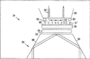
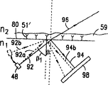
图4的示意图表示的是折射率计22的光电测量系统,它是基于上述的临界角折射计的原理。这个系统包括光敏线性扫描阵列(LSA)44,用于提供随入射在它上面的光的数量和位置而变化的输出信号。线性扫描阵列44包括多个相互靠的很近的并且相互排齐的光电管46。这个测量系统包括光学系统,用于把光引向线性扫描阵列44,其中的照射LSA的光的数量和位置取决于测试样品51的折射率。如图4所示,光学系统包括光源48和棱镜50,以接受从光源48沿光路57来的光。棱镜50包括用于接纳测试样品51的上表面54和与上表面54平行的下表面56,通过下表面54光可以进、出棱镜,并且包括一对内反射侧表面58和60,所说的侧表面58和60与所说的下表面56一起界定了锐角的夹角。在上表面54上设有温度传感器52以读出样品温度,用于温度补偿目的。The schematic diagram of FIG. 4 shows the photoelectric measurement system of the
来自于光源48的光依次经过漫射体62、偏振片64、和准直透镜66。离开准直透镜66的平行光进入干涉滤光片68,干涉滤光片68发出波长为589nm的基本上的单色光。安排会聚透镜70,以接收干涉滤光片68发出的光并且将光集中在反光镜72的方向。反光镜72的取向应使反射光通过棱镜50的下表面56。所说的光再经侧表面58全内反射,以击中上表面54。以小于临界角的角度入射在上表面54上的光的第一部分(未示出)被折射进样品51内。以大于临界角的角度入射在上表面54上的光的第二部分55从上表面54全内反射。光的第二部分55然后通过侧表面60内反射,并经下表面56离开棱镜50。光的第二部分55在通过透镜73后,经反光镜74改变方向,沿线性扫描阵列44的方向前进。因此,在LSA44上光的分布由照射区47和非照射区47a组成,其中所说的照射区47是由光的第二部分55形成的。在两个区47和47a之间的边界称之为阴影线,它在线性扫描阵列44上的位置取决于测试样品51的折射率。Light from
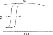
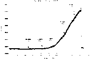
在Leica AR600自动折射率计中,LSA包含接近2600个单个的电荷耦合器件(CCD)元件,每个元件是一个11μm2的正方形。每个CCD(每个像素)都能够把击中它的光的强度转换成电压,随后再通过支持电路将此电压转换成在0和255之间的一个数字的数。每个CCD都产生一个数字强度数值,以此作为输出读数。在图5a中表示的是一个典型的曲线,说明来自裸棱镜的照射强度(空气的基准读数)随单元号的变化。通过按压键盘输入40的“启动”键,可以得到图5a中的空气的基准读数,从而得到基准曲线100,它相当于在没有样品放在棱镜50的上表面54上的条件下线性扫描阵列44的照射分布。当把样品放在棱镜上时,通过样品发出的光的第一部分,光的第二部分55被反射到LSA,照射它的一部分,于是在LSA上形成一个阴影线,如以上参照附图4所述的。通过存储在折射率计22的可编程存储器中的软件程序来确定阴影线位置,将这个位置表示为交叉单元号。在一次读数期间,按基准曲线100的94%制图,制图的结果由图5b中基准曲线100下边的虚线曲线表示,从而形成经过标度的基准曲线120。标度的参数并非一定是94%,它是可以改变的(例如,80%、85%),其目的是在连续的读数期间可实现最佳的精度。然后通过程序寻找交叉单元号,这个程序应能识别样品曲线110与标度的基准曲线120相交的单元或单元的一部分。然后,根据已知折射率的一种物质的校准读数把交叉单元号转换成折射率值。In a Leica AR600 automatic refractometer, the LSA contains approximately 2600 individual charge-coupled device (CCD) elements, each element being an 11 μm square . Each CCD (each pixel) is capable of converting the intensity of the light hitting it into a voltage, which is then converted by supporting circuitry into a digital number between 0 and 255. Each CCD produces a digital intensity value as the output reading. Shown in Figure 5a is a typical curve illustrating the variation of illumination intensity from a bare prism (baseline reading for air) as a function of unit number. A reference reading for air in FIG. 5a can be obtained by pressing the "Start" key of
尽管临界角反射现象过去是已知的,但使临界角折射计作为传感器进入分析领域使之能够检测和监视分析物和对于分析物具有特殊亲合力的粘合层之间的粘合的努力一直都没有成功过。由于和市场上销售的SPA传感器相比,临界角折射计(例如上述的Leica AR600自动折射率计)是很便宜的,因此期望使用临界角折射计来检测和监视粘合现象。因此,需要提供一种利用临界角折射测量原理的方法和器件,以便能够通过测量由于分析物特殊地粘合到在检测表面上固定的粘合层上而产生的折射率变化来检测和监视特定分析物的存在和量。Although the phenomenon of critical angle reflection was known in the past, efforts to bring critical angle refractometers into the analytical field as sensors capable of detecting and monitoring the adhesion between an analyte and an adhesive layer with a specific affinity for the analyte have been Neither worked. Since critical angle refractometers, such as the aforementioned Leica AR600 Automatic Refractometer, are inexpensive compared to commercially available SPA sensors, it is desirable to use a critical angle refractometer to detect and monitor adhesion phenomena. Therefore, there is a need to provide a method and device utilizing the principle of critical angle refractometry in order to be able to detect and monitor specific Presence and amount of analyte.
发明的概述 Overview of the invention
因此,本发明的一个目的是提供一种利用临界角折射测量方法检测和监视在样品分析物和粘合层之间的粘合相互作用的检测器件和方法。It is therefore an object of the present invention to provide a detection device and method for detecting and monitoring adhesive interactions between a sample analyte and an adhesive layer using critical angle refractometry.
本发明的另一个目的是提供一种检测器件,它不用通过利用表面等离子体共振现象测量折射率变化,因此不再需要将粘合层固定在薄金属层上的严格的实验步骤。本发明的相关的目的是避免和金属层的氧化有关的一些问题,以及避免在传统的SPR传感器中必须提供在金属层和玻璃表面之间的中间层。Another object of the present invention is to provide a detecting device which does not require the measurement of the change in the refractive index by using the phenomenon of surface plasmon resonance, thereby eliminating the need for a rigorous experimental procedure of fixing an adhesive layer on a thin metal layer. A related object of the present invention is to avoid some of the problems associated with the oxidation of the metal layer and to avoid having to provide an intermediate layer between the metal layer and the glass surface in conventional SPR sensors.
本发明的下一个目的是提供一种基于临界角的传感器器件,这种器件能被制造并且操作简单。A further object of the present invention is to provide a critical angle based sensor device which can be fabricated and is simple to operate.
本发明的下一个目的是提供一种临界角折射测量方法和设备,用于测量在检测层处的折射率变化,它是让光穿过透光的设计,使光在检测层发生全内反射。The next object of the present invention is to provide a critical angle refraction measurement method and device for measuring the refractive index change at the detection layer, which is designed to allow light to pass through the light transmission, so that the total internal reflection of light occurs at the detection layer .
本发明的下一个目的是提供一种通过测量光在检测层处全反射的临界角、利用临界角折射测量原理检测在接触相中是否存在样品分析物的方法和器件。The next object of the present invention is to provide a method and device for detecting the presence or absence of a sample analyte in a contact phase by measuring the critical angle of total reflection of light at the detection layer, using the principle of critical angle refraction measurement.
本发明的下一个目的是提供一种临界角折射计和方法,用于测量在粘合层和样品分析物之间的粘合反应的速率。A further object of the present invention is to provide a critical angle refractometer and method for measuring the rate of a binding reaction between a binding layer and a sample analyte.
鉴于这些目的和其它目的,通过使用临界角折射计提供一种用于检测接触相中分析物的存在和数量的设备和方法,以检测在样品分析物和固定的粘合层之间的相互作用随着时间的进展发生的检测层的折射率变化。按照本发明的一个实施方案,该设备包括:自动临界角折射计,用于获得样品分析物的折射率数据,所说样品分析物按可操作方式与折射率计的一个光电测量系统相关联;和计算机,对所说计算机进行连接,以便可以与折射率计进行数据通信,用于处理数据和报告折射率随时间的变化而发生的变化。In view of these objects and others, there is provided an apparatus and method for detecting the presence and amount of an analyte in a contact phase by using a critical angle refractometer to detect the interaction between a sample analyte and an immobilized adhesive layer Changes in the refractive index of the detection layer that occur over time. According to one embodiment of the present invention, the apparatus comprises: an automated critical angle refractometer for obtaining refractive index data of a sample analyte operably associated with an optoelectronic measurement system of the refractometer; and a computer coupled for data communication with the refractometer for processing data and reporting changes in refractive index as a function of time.
折射率计测量系统包括由光电管组成的线性扫描阵列和用于引导光朝向LSA的光学系统。击中LSA的光形成一个阴影线,将LSA分成照射部分和暗的非照射部分。阴影线的位置取决于固定在检测表面上的粘合层的折射率。阴影线的位置根据样品分析物是否已经与粘合层粘合而变。因此可以建立阴影线的位置和随折射率的变化而变化的值(样品分析物在接触相中的浓度)之间的相互关系。这个相互关系是通过存储在折射率计的可编程存储器中的软件程序实现的。The refractometer measurement system consists of a linear scanning array of photocells and an optical system for directing light towards the LSA. Light hitting the LSA forms a shadow line that divides the LSA into an illuminated portion and a dark, non-illuminated portion. The position of the hatching depends on the refractive index of the adhesive layer fixed on the detection surface. The position of the hatching varies depending on whether or not the sample analyte has bound to the adhesive layer. A correlation can thus be established between the position of the hatching and the value (concentration of the sample analyte in the contact phase) as a function of the refractive index. This correlation is accomplished by a software program stored in the programmable memory of the refractometer.
按照本发明,提供一种使用临界角折射率计检测和监视分析物和粘合层之间的相互作用的方法。光学系统引导光通过一个或多个透光元件,击中粘合层和透光元件之一之间的界面。在样品分析物和粘合层之间的粘合存在与否将改变粘合层的折射率。粘合层的折射率又影响全反射的临界角。从界面以特定角度反射的光击中LSA,形成阴影线,阴影线的位置可能和粘合到固定的粘合层分析物的量相关联。相同的原理使本发明的方法和设备能够检测和监视折射率变化的速率,折射率变化速率与接触相中分析物的浓度以及分析物和粘合层之间亲合的强度有比例关系。According to the present invention, there is provided a method of detecting and monitoring the interaction between an analyte and an adhesive layer using a critical angle refractometer. The optical system directs light through the one or more light-transmitting elements, hitting the interface between the adhesive layer and one of the light-transmitting elements. The presence or absence of a bond between the sample analyte and the binding layer will change the refractive index of the binding layer. The refractive index of the bonding layer in turn affects the critical angle for total reflection. Light reflected from the interface at a specific angle hits the LSA, forming a shadow line whose position may correlate with the amount of analyte bound to the immobilized adhesive layer. The same principle enables the methods and devices of the present invention to detect and monitor the rate of change in refractive index that is proportional to the concentration of the analyte in the contact phase and the strength of the affinity between the analyte and the binding layer.
本发明还提供一种用于通过测量在粘合层的折射率变化检测对于粘合层有特定亲合力的特定分析物是否存在的设备和方法。这样的检测可以在实验室测试中和家用测试箱中实施。该方法包括以特定的入射角引导准直光束穿过一个或多个透光元件,击中粘合层和透光元件之一之间的界面。根据是否存在对于粘合层有特定亲合力的特定分析物,光的入射角将满足或不满足全内反射的条件。如果满足全内反射条件,则反射光将击中沿反射光的光路设置的LSA或其它能够检测光的检测器。因此,根据检测器是否由全内反射的光照射,就可确定分析物的存在与否。还设想,可设置LSA,以便可以根据是否满足全内反射条件检测照射到LSA的透射光。实施上述方法的一种设备包括以特定的入射角在界面上引导一个准直光束。为了检测全反射的临界角,提供能够移动和改变入射角的单个光源。在该设备的一个可替换实施方案中,利用在界面上以不同的角度引导光束的多个光源检测分析物的存在与否。根据在分析物和固定的粘合层之间是否已经发生粘合,来自于光源之一的光在界面上发生全内反射,因而照射光传感器并指示分析物存在与否。The present invention also provides an apparatus and method for detecting the presence of a specific analyte having a specific affinity for the bonding layer by measuring a change in the refractive index of the bonding layer. Such detection can be performed in laboratory tests and in home test kits. The method includes directing a collimated light beam through one or more light-transmitting elements at a specific angle of incidence, hitting an interface between the adhesive layer and one of the light-transmitting elements. Depending on the presence or absence of a particular analyte with a particular affinity for the binding layer, the angle of incidence of the light will satisfy or fail the condition for total internal reflection. If the condition of total internal reflection is met, the reflected light will hit an LSA or other detector capable of detecting light positioned along the optical path of the reflected light. Thus, depending on whether the detector is illuminated by total internally reflected light, the presence or absence of the analyte can be determined. It is also contemplated that the LSA can be arranged so that transmitted light hitting the LSA can be detected based on whether the condition of total internal reflection is satisfied. An apparatus for carrying out the method described above includes directing a collimated light beam at an interface at a specified angle of incidence. In order to detect the critical angle for total reflection, a single light source capable of moving and changing the angle of incidence is provided. In an alternative embodiment of the device, the presence or absence of the analyte is detected using multiple light sources directing light beams at different angles at the interface. Depending on whether adhesion has occurred between the analyte and the immobilized adhesive layer, light from one of the light sources is totally internally reflected at the interface, thus illuminating the light sensor and indicating the presence or absence of the analyte.
在本发明的实施方案之一中,一种专用的测试设备允许在接触相中的分析物和固定的粘合层之间按可操作方式发生关联。在优选实施方案中,该设备包括薄的透光元件,在其上表面上固定所选类型的配位体,形成粘合层。在透光元件上方封闭地安排一个流动室,用于提供包含样品分析物的接触相的缓冲流动,该样品分析物与固定的粘合层有特定粘合相互作用。确定安排在盘的上表面的O形圈或垫的大小,以便在该元件的上表面的粘合层和流体室之间提供不透流体的周边密封。在透光元件的下表面和折射率计棱镜的上表面之间提供高折射率耦合液体。透光元件,例如盘,最好由玻璃、聚苯乙烯、聚碳酸酯、或其它具有合适的折射率的透光材料形成。特定的固定技术通常部分取决于形成盘所用的材料。例如,可以将一种抗体,例如抗-链亲合素抗体固定在透光盘的上表面,并且在缓冲流中引入它的抗原链亲合素,以便分析粘合相互作用。另一个例子是关于DNA粘合蛋白质/DNA配位体相互作用,0ccR蛋白质可以固定在透光盘的上表面,它的寡核苷酸靶在接触相中引入,以便分析粘合相互作用。In one of the embodiments of the present invention, a dedicated testing device allows an operative correlation between the analyte in the contacting phase and the immobilized adhesive layer. In a preferred embodiment, the device comprises a thin light transmissive member on the upper surface of which a selected type of ligand is immobilized, forming an adhesive layer. A flow chamber is hermetically arranged above the light-transmissive element for providing a buffered flow of a contact phase containing sample analytes having specific adhesive interactions with the immobilized adhesive layer. An O-ring or pad disposed on the upper surface of the disc is sized to provide a fluid-tight peripheral seal between the adhesive layer and the fluid chamber on the upper surface of the element. A high refractive index coupling liquid is provided between the lower surface of the light transmissive element and the upper surface of the refractometer prism. The light transmissive element, such as the disc, is preferably formed of glass, polystyrene, polycarbonate, or other light transmissive material with a suitable refractive index. The particular fixation technique will generally depend in part on the material used to form the disc. For example, an antibody, such as an anti-streptavidin antibody, can be immobilized on the upper surface of a translucent disk and its antigenic streptavidin introduced in a buffered flow for analysis of adhesive interactions. As another example regarding DNA-binding protein/DNA ligand interactions, the OccR protein can be immobilized on the upper surface of a transparent disc and its oligonucleotide target introduced in the contact phase to analyze the binding interaction.
本发明还可包括一种在涉及分析物的特定反应期间监测特定粘合的方法,该方法包括:在透光元件上固定一粘合层;使透明元件按可操作方式与一个自动临界角折射率计的光电测量系统发生关联,引入包含分析物的接触相以接触粘合层,使用临界角折射率计产生测量数据,其中包括的数据是以规律的时间间隔的粘合层折射率的函数,并且处理测量数据以便可以分析所说的分析物粘合到粘合层的进展情况。The present invention may also include a method of monitoring a specific adhesion during a specific reaction involving an analyte, the method comprising: securing an adhesive layer on a light transmissive element; operatively aligning the transparent element with an automatic critical angle refraction The photoelectric measurement system of the index meter is correlated, the contact phase containing the analyte is introduced into contact with the bonding layer, and the critical angle refractometer is used to generate measurement data, which includes data as a function of the refractive index of the bonding layer at regular time intervals , and the measured data are processed so that the progress of the binding of the analyte to the adhesive layer can be analyzed.
附图的简要说明 Brief description of the drawings
在下面结合附图的各个实施方案的详细描述中将要更加全面地描述本发明的操作方式和本质。The operation and nature of the present invention will be more fully described in the following detailed description of various embodiments taken in conjunction with the accompanying drawings.
图1是SPR检测器的示意图;Fig. 1 is the schematic diagram of SPR detector;
图2是SPR检测器的强度随入射角变化的曲线;Fig. 2 is the curve that the intensity of SPR detector changes with incident angle;
图3a是临界角折射计示意图;Figure 3a is a schematic diagram of a critical angle refractometer;
图3b是按照本发明的传感器设备的透视图,其中包括自动临界角折射计;Figure 3b is a perspective view of a sensor device according to the present invention including an automatic critical angle refractometer;
图4是图3a所示的自动折射率计的光电测量系统的示意图;Figure 4 is a schematic diagram of the photoelectric measurement system of the automatic refractometer shown in Figure 3a;
图5a是表示在空气中启动的折射计的基准曲线的曲线图;Figure 5a is a graph showing a reference curve for a refractometer activated in air;
图5b是表示照射强度随阵列单元数变化的曲线;Figure 5b is a curve representing the variation of irradiation intensity with the number of array elements;
图6是表示本发明的校准曲线的示意图;Figure 6 is a schematic diagram representing a calibration curve of the present invention;
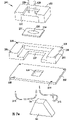
图7是本发明的优选测试装置的分解示意图;Figure 7 is an exploded schematic view of a preferred testing device of the present invention;
图7a是本发明的一个实施方案的基座和平板的透视图;Figure 7a is a perspective view of the base and plate of one embodiment of the present invention;
图7b是基座和带有滑块的平板的透视图;Figure 7b is a perspective view of the base and the plate with the slider;
图7c是流动室盖的透视图;Figure 7c is a perspective view of the flow chamber cover;
图7d是装配好的流动室/滑块和透视图;Figure 7d is a perspective view of the assembled flow chamber/slider;
图7e是图7a-7d中所示的实施方案的分解图;Figure 7e is an exploded view of the embodiment shown in Figures 7a-7d;
图8是表示加入蔗糖对于折射率的影响的曲线图;Figure 8 is a graph showing the effect of adding sucrose on the refractive index;
图9是表示加入牛血清清蛋白对折射率的影响的曲线图;Figure 9 is a graph showing the effect of adding bovine serum albumin on the refractive index;
图10a是表示通过测量临界角检测到的折射率随里间的变化曲线图,这种变化来自于固定在Xenobind玻璃滑块上的兔的抗羊抗体和接触溶液中羊的IgG抗原之间的粘合;Fig. 10a is a graph showing the variation of the refractive index detected by measuring the critical angle, which comes from the adhesion between the rabbit anti-goat antibody immobilized on the Xenobind glass slide and the goat IgG antigen in the contact solution. combine;
图10b是包含和图10a对应的拟合数据的一系列曲线;Figure 10b is a series of curves containing the fitted data corresponding to Figure 10a;
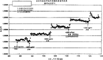
图11a是表示通过测量临界角检测到的折射率随里间的变化的曲线图,这种变化来自于固定在Xenobind玻璃滑块上的山羊的抗鼠抗体和接触溶液中鼠的IgG抗原之间的粘合;Figure 11a is a graph showing the change in refractive index as a function of time, detected by measuring the critical angle, resulting from the interaction between goat anti-mouse antibody immobilized on a Xenobind glass slide and mouse IgG antigen in the contact solution. bonding;
图11b是包含和图11a对应的拟合数据的一系列曲线;Figure 11b is a series of curves containing the fitted data corresponding to Figure 11a;
图12是表示生物素化玻璃和中性抗生物素蛋白结合的山羊的抗鼠抗体之间的粘合对于折射率的影响的曲线图;Figure 12 is a graph showing the effect of adhesion between biotinylated glass and neutravidin-conjugated goat anti-mouse antibody on the refractive index;
图13a是表示非粘合的和粘合的配位体对于折射率的影响;Figure 13a is a graph showing the effect of non-binding and binding ligands on the refractive index;
图13b是包含和图13a对应的拟合数据的一系列曲线;Figure 13b is a series of curves containing the fitted data corresponding to Figure 13a;
图14是用来限制在支撑固定的反应物的透明圆盘只有一侧产生化学激活的一种安排的剖面图;Figure 14 is a cross-sectional view of an arrangement for limiting chemical activation to only one side of a transparent disc supporting immobilized reactants;
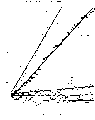
图15a是本发明的一个实施方案的光学系统的示意图;Figure 15a is a schematic diagram of the optical system of one embodiment of the present invention;
图15b是本发明的另一个实施方案的光学系统的示意图;Figure 15b is a schematic diagram of an optical system according to another embodiment of the present invention;
图15c是本发明的另一个实施方案的光学系统的示意图;Figure 15c is a schematic diagram of an optical system according to another embodiment of the present invention;
图16a是表示通过测量临界角检测到的折射率随里间的变化的曲线图,这种变化来自于生物素化玻璃和中性抗生物素蛋白结合的山羊的抗鼠IgG抗体之间的粘合对于折射率的影响的曲线图;Figure 16a is a graph showing the change in refractive index as a function of time detected by measuring the critical angle resulting from the adhesion between biotinylated glass and neutravidin-conjugated goat anti-mouse IgG antibody A graph of the effect on the refractive index;
图16b是表示和图16a对应的试验中光强度变化的曲线图;Figure 16b is a graph showing the change in light intensity in the test corresponding to Figure 16a;
图16c是表示和图16a对应的试验中阴影线变化的曲线图;Figure 16c is a graph representing the change in hatching in the test corresponding to Figure 16a;
图16d是表示和图16a对应的试验在开始时的阴影线位置的曲线图;Figure 16d is a graph representing the position of the hatched line at the beginning of the test corresponding to Figure 16a;
图17a是本发明的载玻片的透视顶视图;Figure 17a is a perspective top view of a glass slide of the present invention;
图17b是图17a所示的载玻片的透视底视图;Figure 17b is a perspective bottom view of the slide shown in Figure 17a;
图17c是载玻片的底视图;Figure 17c is a bottom view of a glass slide;
图17d是载玻片的顶视图;Figure 17d is a top view of a glass slide;
图17e是图17a-d所示的载玻片的剖面图。Figure 17e is a cross-sectional view of the slide shown in Figures 17a-d.
发明的详细描述 Detailed description of the invention
在下面的对于本发明的详细描述中,参照构成本发明的一部分的附图,在附图中,借助于图示表示出实施本发明的优选实施方案。对于这些实施方案的描述足够细致,以使本领域的普遍技术人员能够实施本发明,并且可以理解,还可以利用其它的实施方案,并且在不偏离本发明的构思和范围的条件下,还可以进行其它的逻辑上的、机械的、化学的、和电学的变化。因此,下面的描述不是限制性的,本发明的范围仅由所附的权利要求书确定。In the following detailed description of the invention, reference is made to the accompanying drawings which form a part hereof, and in which is shown by way of illustrations preferred embodiments for practicing the invention. These embodiments have been described in sufficient detail to enable those of ordinary skill in the art to practice the invention, and it will be appreciated that other embodiments can be utilized and that other embodiments can be used without departing from the spirit and scope of the invention. Other logical, mechanical, chemical, and electrical changes are made. Therefore, the following description is not limiting, and the scope of the present invention is determined only by the appended claims.
为了实现本发明的目的和原理,使用自动临界角折射计检测光检测器(如,LSA)上的阴影线,并因此分辨接触相的全反射临界角,所说的接触相设置在透光元件上,且该透光元件具有粘合层。粘合层,其包括对接触相中的分析物有特殊的亲合力的配位体。(在本说明书中,术语“样品“和“接触相“可互换使用)。当分析物粘合到粘合层上,粘合层的光学密度发生了变化。在下面描述的几个实验性的试验中,使用临界角折射计检测粘合层的光学密度由于粘合现象引起的变化。下面描述的实验结果表明,使用当前有的Leica AR600自动折射率计的光电配置,能够检测到由于粘合层和样品分析物之间的粘合引起的很小折射率变化,所说的这种自动折射率计能够在相当宽的折射率范围进行折射率测量。试验结果证实,使用临界角折射测量方法检测和监视粘合层的光学密度变化是成功的,粘合层的光学密度变化是由分析物和粘合层之间的粘合相互作用引起的。In order to realize the purpose and principle of the present invention, an automatic critical angle refractometer is used to detect the shadow line on the photodetector (eg, LSA), and thus distinguish the critical angle of total reflection of the contact phase, which is arranged on the light-transmitting element on, and the light-transmitting element has an adhesive layer. A binding layer that includes ligands with specific affinity for analytes in the contact phase. (In this specification, the terms "sample" and "contact phase" are used interchangeably). When analytes bind to the adhesive layer, the optical density of the adhesive layer changes. In several experimental tests described below, a critical angle refractometer was used to detect changes in the optical density of the adhesive layer due to the adhesion phenomenon. The experimental results described below demonstrate that, using the optoelectronic configuration of the currently available Leica AR600 automatic refractometer, it is possible to detect very small changes in the refractive index due to binding between the adhesive layer and the sample analyte, the so-called Automatic refractometers are capable of making refractive index measurements over a fairly wide range of refractive indices. The experimental results confirmed the success of using critical angle refractometry to detect and monitor the change in optical density of the adhesive layer, which is caused by the adhesive interaction between the analyte and the adhesive layer.
图7表示一个测试装置24,用于完成本发明的优选实施方案的折射测量。在图7所示的测试装置中,细节处略微分解。测试装置24包括高折射率耦合液体76,它直接引入到临界角折射计22(未示出)的棱镜50的上表面54,还包括带有粘合层51′的透光元件,例如盘78,粘合层51′淀积在盘78和粘合层之间的界面80上,在流动室28和界面80之间插入密封O形圈82。在此实施方案中,棱镜50是折射率约为1.7的蓝宝石棱镜。Fig. 7 shows a
粘合层51′包括固定在界面80上的配位体53。配位体53对于包含在接触相59中的样品分析物可以有或者可以没有特殊的亲合力。在本发明的优选实施方案中,接触相59是通过流动室28传递到接触粘合层51′的液相。接触之后,接触相59中的样品分析物接触配位体53,并且,如果分析物和配位体相互之间具有特殊的亲合力,则所说的样品分析物粘合到配位体53上,允许粘合现象发生。粘合层51′的一个例子是固定在界面80上的一种抗体基质。接触相59例如是用于与粘合层51′的抗体基质相互作用的一种抗原溶液,通过流动室28传递这种接触相59,并且借助于临界角折射计监视这种相互作用。
流动室28可以是一个常规的流动室。在本发明的一个实施方案中,能够提供约为1ml/分钟流速的流动室,例如可从Leica Microsystem Inc.得到的Catalog No.10610型流动室覆盖界面80的绝大部分。适当的耦合液体是高折射率油,最好是折射率为1.63的油。透明盘78可以由对于入射光是透明的材料构成,例如玻璃、塑料、或其它折射率适宜的透光材料构成。在所述的实施方案中,入射光的波长是589nm。在优选实施方案中,盘78在20℃的折射率大于1.52。这种材料例如是玻璃、聚苯乙烯、聚碳酸酯。试验中所用的适宜的盘厚度为0.17nm。
在图7a-7e中表示出流动室/透明盘试验装置的另一个实施方案。在该实施方案中,流动室的基座200放置在平板202上,平板202有一个开口204,可以露出棱镜50(棱镜未示出)的上表面54,如图7a所示的。可以通过任何常规方式将基座200附着到平板202上,其中包括简单地将基座放在平板上,或使用螺丝或其它等效方式穿过开口206将基座紧固到平板上,如图7a所示。一滴耦合液体76(如图7所示)滴到上表面54,或者是手动地滴上,或者是先通过将耦合液体76滴入第一板开口208再使其带到上表面54。这溶液流过和板开口208相连的第一管210,并到达上表面54。如果有过多的耦合液体76流到上表面54,则第二管212从上表面54向第二板开口214排放过多的耦合液体,如图7e所示。Another embodiment of the flow cell/transparent disc test device is shown in Figures 7a-7e. In this embodiment, the
图7b示出基座200和平板202,在板202上放置透光的载玻片218(类似于上述的透光盘78)。载玻片218设在棱镜的上表面54的上方,并且设在适于容纳载玻片的位于基座200内的框架207内。框架207界定了载玻片218相对于棱镜的上表面54的位置。在图7b中,框架207是长方形形状,可以容纳长方形的载玻片218并且部分地包围载玻片218。如图7e所示,在一个实施方案中,载玻片218包括一个透光区236和一个磨砂区237,透光区236上固定粘合层,磨砂区237用于俘获和漫射照射区域237的光。可以对区237进行蚀刻,或用机械方法使其磨薄,以产生磨砂效果。Figure 7b shows a
图7c表示流动室的盖240,具有管226和228用于通过流动室循环接触相。盖240包括具有孔222的盖框架230。从基座200伸出的一个或多个带有螺纹的短柱216穿过盖框架230中的孔222,然后最好通过滚花螺母234固定就位,如图7d所示。管226和228经过装配到盖框架230中的上部232耦合到流动室,如图7c、7d、7e所示。上部232附着到盖框架230上的方式可以是永久性的,或者是可拆卸的。管226和228向载玻片218传递接触相59(如图7所示)。接触相通过管226或228之一进入流动室,流过载玻片并且通过另一个管离开流动室。期望是,上部232可以包括温度传感器或用于测量在流动室中循环的流体的各种性质的任何其它传感器。这样一种传感器可以放置在上部232的表面上,在折射计操作期间通常与接触相接触。Figure 7c shows the
现在参照附图17a-17e更加详细地描述参照附图7a-7e描述的流动室装置中使用的载玻片218的特定几何形状和设计。所示的载玻片218有上表面250,上表面250有第一抬高部分252(图17a)。上表面250有磨砂面层,用于漫射或俘获不期望出现的光,防止不期望出现的光进入检测系统被光检测器检测到。磨砂面层可以通过化学的或机械的蚀刻或任何其它的以特定应用所设想的方法实现。第一抬高部分252不经蚀刻,保持透光状态。在图17e中表示出载玻片218的侧视剖面图,表示出抬高部分252,抬高部分252有附着粘合层51′的检测表面253。在图17a-d所示的实施方案之一中,第一抬高部分252的形状类似于椭圆形,有长轴X。在图7b中表示的垫圈220通常放在第一抬高部分252上,以便密封测量期间接触相的循环区。图7b中的垫圈220也作成椭圆形的,以便和图17a的第一抬高部分252的形状平行。The specific geometry and design of the
图17b中的载玻片218的下表面254类似于上表面250,下表面253的磨砂面层可以防止不期望的光进入折射计的检测系统。第二抬高部分256不蚀刻,保持透光。在一个实施方案中的第二抬高部分呈泪珠形状,其长轴Y垂直于轴X。第三抬高部分也是透光的,并且包括垫环258,当将载玻片放在平板上时,垫环258接触平板202(如图7a所示)。传递到垫环258的上表面54的耦合液体76接触第二抬高部分256,并且把载玻片218耦合到上表面54,如图7a所示。The
如图17c-17d所示,由抬高部分252和256界定的透明重叠区260将是穿过载玻片218和照射表面253的光发生反射或透射的区域,表示出在粘合层51′和接触相中的分析物之间的粘合相互作用是否存在。如图17d所示,椭圆形部分252从第一端262到第二端264的延伸部分超过了重叠区260。流动室中的接触相首先接触载玻片218的第一端262或第二端264。在接触相从第一端262或第二端264流到重叠区260时,接触相中的任何涡流都将减小,接触相的流动变为层流,从而改善了在检测表面上的粘合反应的测量精度。As shown in Figures 17c-17d, the
如图17a和17d所示,本发明的企图是使载玻片218的表面250包括代码区270,代码区270包含标记或嵌入的芯片。包含在代码区270中的标记可以是可读的光学图案,可以接任何期望的方式提供有关附着到载玻片的特定粘合层、载玻片材料的折射率、或者特定的载玻片的信息。标记还可以用来辨认载玻片是否在测量阶段开始之前正确地插入流动室。如果代码区270包含芯片,则这个芯片可能会以不同的代码信号响应于某种能量(如射频能量)。响应于不同的代码信号,该芯片将提供有关特定载玻片、固定到检测表面的粘合层、载玻片的取向的信息或其它期望的信息。代码区270可以定位在载玻片的任何表面上或者定位在载玻片的里面,这取决于载玻片、流动室、和折射计的特定设计。As shown in Figures 17a and 17d, it is contemplated by the present invention that the
应该注意的是,在不偏离本发明的权利要求书的范围的条件下,还可以使用在上边具有粘合层的载玻片218的其它几何形状和设计。It should be noted that other geometries and designs of the
需要说明的是,使用盘78支撑粘合层是优选的作法,但不是在实施本发明的所有的方案中必须的。之所以如此,是因为例如粘合层51′可在没有盘78的情况下直接固定在棱镜50上。在这种情况下,接触相59中的样品分析物接触直接固定在棱镜50上的配位体53。在这种设计中,以及在其它可能的设计中,只要满足全内反射的条件,就可以实现粘合现象的折射测量。It should be noted that the use of
的确,可以使用各种设计以在界面80满足全内反射条件从而确定临界角。例如,可以定位光检测器,以检测在界面全内反射的光部分(如在本发明的优选实施方案中那样),或者检测透过界面进入粘合层中的光部分。在这两种情况下,在传感器上的阴影线的位置都代表粘合层的折射率,因此,代表在粘合层中发生的粘合现象。此外,界面80或者可由透射光照射,或者可由反射光照射。当通过任何光学系统(不一定是包括用于引导光进入界面的棱镜的光学系统)照射界面时,也可以满足全内反射条件。在本发明中成功地使用了这样的光学系统,例如将光引向界面的透镜或反光镜的设计。只要在界面80上入射的光以满足全内反射的角度照射界面,就可以进行粘合现象的折射测量。Indeed, various designs can be used to satisfy the condition of total internal reflection at
例如(但并非限制),适合于和本发明的临界角折射计一道使用的各种粘合层可以包括固定在透明盘上的下述配位体。第一个例子是涂有羧基葡聚糖的玻璃盘。在这个例子中,首先将一层葡聚糖化学结合到透明的玻璃盘78的表面上。在将葡聚糖固定在盘78上后,用包含羧基作为葡聚糖分子的端基的几种不同的化学试剂之一使葡聚糖改性。这个改性的步骤提供了羧甲基,通过众所周知的EDC/NHS化学方法,使用羧甲基去结合这种如蛋白质的配位体。在这个改性步骤使用的化学试剂的例子包括:氯乙酸、溴乙酸、6-溴己酸。在葡聚糖改性后,可以实现如蛋白质的粘合层到羧基的直接固定,可进行葡聚糖的进一步的改性,以便可以使用公知的EDC(1-乙基-3-(3-二甲胺丙基)碳二亚胺)化学方法将一个端胺基固定到这个葡聚糖上。For example, and without limitation, various adhesive layers suitable for use with the critical angle refractometer of the present invention may include the ligands described below immobilized on a transparent disc. The first example is a glass dish coated with carboxydextran. In this example, a layer of dextran is first chemically bonded to the surface of a
粘合层的另一个例子包括硅烷分子,硅烷分子共价结合到由硅石制成的盘78的表面上的-Si-OH基上。根据定位在结合的硅烷分子的端基处的官能团,可以实现蛋白质的直接固定。按另一种方式,进一步地表面改性,即将分子附着到硅烷分子上,可以得到用于蛋白质(配位体)固定的另一些官能基。在市场上可以得到的硅烷分子的例子是:γ-环氧丙氧丙基三乙氧基硅烷,和3-氨基丙基三乙氧硅烷。这些硅烷分子的端基处(粘合层固定发生的端基处)的官能团分别是羟基和胺基。按另一种方式,可以向硅烷附着双官能团,例如戊二醛,然后将配位体附着到这个官能团上。双官能团用作间隔基的臂,可以使位阻效应最小并提供至配位体的活性位置的通路。Another example of an adhesive layer includes silane molecules covalently bonded to -Si-OH groups on the surface of the
为了获得涂有抗生物素蛋白/链亲和素的玻璃盘,使用类似于在硅烷化过程中描述的化学方法,将抗生物素蛋白和链亲和素结合到盘78的玻璃表面上。一旦硅烷结合到玻璃表面上,抗生物素蛋白/链亲和素就固定到双官能间隔基的臂上。由于生物素-抗生物素蛋白相互作用的特征是可以得到最高的亲合力,具有已附着的抗生物素蛋白/链亲和素的表面对于生物素具有极高的亲合力。只通过使生物素化蛋白质与抗生物素蛋白接触,就能够很容易地把生物素化蛋白质结合到涂敷的玻璃上。To obtain avidin/streptavidin-coated glass discs, avidin and streptavidin were bound to the glass surface of the
在粘合化学方法的另一个例子中,生物素分子结合到由玻璃制成的盘78的表面上,从而产生初始的生物素化玻璃表面。通过使用类似于在硅烷化过程中描述的化学方法可以实现粘合,产生生物素化玻璃。然后,在生物素化玻璃表面上有选择地吸收抗生物素蛋白/链亲和素分子,于是产生了对于生物素分子有高亲合力的表面,这个表面类似于涂有抗生物素蛋白的表面。然后将生物素化蛋白质附着到这个表面上。在此例中,在不破坏初始的生物素化玻璃表面的条件下再生这个表面。按另一种方式,可以将抗生物素蛋白/链亲和素/中性抗生物素蛋白结合的蛋白质直接耦合到生物素化玻璃上。In another example of adhesion chemistry, biotin molecules are bound to the surface of a
当透明盘78由塑料制成时,可以利用好几种化学技术将各种配位体固定到塑料表面上。其中的一种技术是在不改性或激活蛋白质的条件下,被动吸收蛋白质到一种疏水的塑料材料上。优选的疏水材料是聚苯乙烯。在这种技术中,静电吸引使得在蛋白质上的正电荷“粘结“到带负电的塑料上。通过控制诸如pH、离子强度、和培育周期之类的参数,可实现配位体(蛋白质)的粘合。这里的培育周期是让包含蛋白质的溶液与盘表面接触的时间长度。When the
另一种可以利用的技术在其初始步骤涉及到粘合戊二醛到塑料表面上,使醛基留在末端。然后利用醛基去固定蛋白质。这样一种技术通常导致所固定的蛋白质的数量的增加。涉及塑料表面的其它技术是利用光激活的交联剂。在这种技术中,固定的酶与交联剂分子结合,然后,通过紫外光曝光将其结合到塑料表面上。Another technique that can be used involves in its initial step the binding of glutaraldehyde to the plastic surface, leaving the aldehyde groups at the ends. The aldehyde group is then used to immobilize the protein. Such a technique generally results in an increase in the amount of protein immobilized. Other techniques involving plastic surfaces utilize light-activated crosslinkers. In this technique, immobilized enzymes are combined with crosslinker molecules, which are then bound to plastic surfaces by exposure to UV light.
本发明还设想,利用在透明玻璃或塑料表面上的自动成型的类脂单层来固定膜结合的蛋白质或对于疏水表面有亲合力的其它配位体。总括起来,适宜的粘合层可以是;羧甲基化葡聚糖、醛激活葡聚糖、酰肼激活葡聚糖、硅烷表面、硅烷化表面、硅烷、抗生物素蛋白、链亲和素、中性抗生物素蛋白、生物素基、双官能间隔基的臂、自动成型的单层、类脂、和无改变的或非涂敷的玻璃或塑料表面。适宜的分析物可以是抗原、蛋白质、糖蛋白、维生素、微生物、包括细菌和细菌碎片的微生物块、病毒、病毒物质块、类脂、碳水化合物、毒素、DNA、RNA、DNA和RNA的类似物、致病的有机分子、抗细菌和抗病毒的有机分子以及它们的类似物、治疗用的试剂和药品。The present invention also contemplates the use of self-forming lipid monolayers on clear glass or plastic surfaces to immobilize membrane-bound proteins or other ligands that have an affinity for hydrophobic surfaces. In summary, suitable adhesive layers can be; carboxymethylated dextran, aldehyde-activated dextran, hydrazide-activated dextran, silane surface, silanized surface, silane, avidin, streptavidin , neutravidin, biotin-based, bifunctional spacer arms, autoformed monolayers, lipids, and unaltered or uncoated glass or plastic surfaces. Suitable analytes may be antigens, proteins, glycoproteins, vitamins, microorganisms, microbial clumps including bacteria and bacterial fragments, viruses, clumps of viral material, lipids, carbohydrates, toxins, DNA, RNA, analogs of DNA and RNA , pathogenic organic molecules, antibacterial and antiviral organic molecules and their analogs, therapeutic agents and pharmaceuticals.
在下面详细描述的实验性试验中,在图3b所示的实验设备中使用折射计22。图3b中所示的是按照本发明形成的实验设备,用标号20泛指这个设备。设备20一般说来包括:具有试验装置24用于测量折射率的自动折射率计22、用于存贮流体接触相的贮罐26、界定靠近试验装置24的一个井29(见图7)的流动室28、用于传递接触相从贮罐26到流动室28的泵25和软管27、为与折射计22进行串行通信而进行连接的个人计算机30,用于控制折射计的测量功能,并且用于处理和存储从折射计接收的测量数据。In the experimental experiments described in detail below, a
折射计22进一步包括一个RS-232串行端口(未示出),用于借助于标准串接电缆42和外围设备进行数据连接,大部分通用的个人计算机30都有它自已的串行通信端口(COM1或COM2)。可以通过在计算机上运行的任何终端通信软件程序控制折射计22和计算机30之间的通信。然而,随Mirosoft Windows3.11的终端程序以及随MirosoftWindows95的超级终端程序都是公知的,能够在折射计22和计算机30之间进行数据通信以便按照本发明的方法提取实时测量数据。对于终端程序推荐的通信端口设备是:波特率-19200,数据位-8,停止位-1,奇偶校验-无,流动控制-XON/XOFF。在菜单下,选项5“设置“,然后,选项“文本传送“,应该选择“标准流量控制“。保留这些选项以备将来使用是有益的。如通过参照Leica AR600自动折射率计的用户手册和支持文件可以更加全面理解地那样,通过用户输入和发送各种控制码,可以从计算机30遥控折射计。虽然这里概述的本发明的设备包括链接到个人计算机30的自动折射率计22,当然还有可能在在折射计22本身内部提供可编程软件和存储器,这将使仪器在各种检测应用中能够连续操作并在选定的规则间隔记录读数。The
重要的是要记住,在市场上可以得到的Leica AR600自动折射率计中,LSA的#100单元的交叉点对应于在20℃约为1.3的折射率,LSA的#2450单元的交叉点对应于在同一温度下约为1.52的折射率。由于大部分粘合现象引起的折射率变化范围从约1.3到约1.4,所以可以成功地使用Leica AR600自动折射率计结构的折射率测量的这个宽的变化范围。It is important to remember that in the commercially available Leica AR600 automatic refractometer, the intersection of
总括起来,这里描述的7个实验涉及到两个大的阶段:第一,制备支撑表面,并且在支撑表面上固定粘合层;第二,通过临界角折射测量方法连续测量玻璃和粘合层之间的界面的折射率变化。在向接触相添加非粘合溶液后并且在样品分析物和粘合层之间发生粘合反应期间进行这种测量。In summary, the seven experiments described here involved two large phases: first, the preparation of the support surface and the fixation of the adhesive layer on the support surface; second, the continuous measurement of the glass and the adhesive layer by critical angle refractometry The refractive index changes at the interface between them. This measurement is performed after the addition of the non-binding solution to the contact phase and during the binding reaction between the sample analyte and the binding layer.
在试验1和2中,通过添加蔗糖和牛血清清蛋白来改变流动的接触相的质量。添加的目的是为了确定在耦合到Leica AR600临界角折射率计上的玻璃载玻片的表面上测量折射率变化的实际可行性。In
在试验3和4中,通过共价结合到硅烷化玻璃盘上固定抗体,它包含终止在醛基中的专用的间隔基的臂。在每个试验中,对于随时间添加的抗原的5个连续增加的浓度进行测量。In experiments 3 and 4, antibodies were immobilized by covalent binding to silanized glass discs containing arms with proprietary spacers terminated in aldehyde groups. In each experiment, measurements were made for 5 successively increasing concentrations of antigen added over time.
在试验5中,在一个生物素化玻璃表面上吸附中性抗生物素蛋白结合的羊抗鼠IgG抗体。在试验6和7中,实验包括固定的羊抗鼠IgG抗体与羊IgG的反应,所说的羊IgG是一种控制溶液和特殊粘合的抗原鼠IgG。在相应的附图中给出从试验1-7记录的测量数据。In
透明盘78的制备涉及到硅烷化和随后盘的高碘酸盐氧化。虽然在市场上可以得到硅烷化的盘并且可以用来实施本发明,但是完成折射率合适的平-平玻璃板(该板的折射率大于接触相的期望折射率)的硅烷化是为了保证在试验1和2中有高的质量。在试验中使用的透明盘78通过相继浸入浓硫酸、蒸馏水、乙醇、和丙酮中进行初始的清洁和羟基化。从Sigma-Aldrich Chemicals公司获得500克硫酸,产品型号为S-126,ACS试剂级,纯度为95.7%。将透明盘78浸入硫酸中一次,10分钟,然后浸入蒸馏水中3次,每次10分钟。从Sigma-AldrichChemicals公司获得乙醇,产品型号为27074-1,试剂、变性、HPLC级。将透明盘78浸入乙醇两次,每次浸入10分钟。。从Sigma-AldrichChemicals公司获得丙酮,纯度为99.9%,ACS试剂级。将透明盘78浸入丙酮中两次,每次10分钟的周期。将透明盘78支撑在由单股铜线形成的线支撑钩上,就可实现各个浸入。从横跨一个试剂室顶部的杆架吊下几个这样的钩,每个钩上都通过在盘周围弯曲线的方式安装一个透明盘。作为单个浸入钩的替换,为了进行浸入,可以专门加工一个或多个支架,支架上有一排按规则的间隔分开的用于保持透明盘78和空间。Preparation of the
一旦透明盘78已经清洁,必须用3-氨基丙基三乙氧基硅烷(以下称APTS)激活这些透明盘。一个APTS分子包含一个硅烷原子,硅烷原子经一个氧原子结合到3个乙基上(三乙氧基硅烷)。在涉及界面80上的羟基的凝聚反应期间,分子的这个部分直接接合到透明盘78的界面80上,在水环境中的自由质子亦是如此。为了完成一批20个盘的该反应,将2.5ml的APTS与25ml的蒸馏水混合,产生10%wt/vol的新鲜的APTS水溶液。使用冰醋酸(从Sigma-Aldrich Chemicals公司获得,产品号为A-0808)和一台电子pH测量仪将这种溶液滴定成5.0的pH值。透明盘78与耦合试剂APTS的反应控制在80℃,历时3个小时。Once the
图14表示用来限制化学活化仅在每个透明盘78的一侧的一种设计。透明盘78放在一个窄的坚固的表面上,如一个透明载玻片84的表面上,要活化的样品表面向上,如图所示。在透明盘78的顶部放置一个橡胶的O形环86,环86的内径为8-9mm。对于这个O形环86的大小进行选择,使其和实际折射读数期间放在流动室28和透明盘78之间的O形圈86的大小相同,或者略大一点,以保证在折射测量期间暴露到样品分析物的所有样品表面被活化。在O形环86的顶部放置一段管88,管88的内径对应于O形环的内径,管88的高度不大于25mm。可以理解,O形环86将在透明盘78和管88之间产生流体密封。管88在其升高的部分包括一对直径方向相对的通孔,用于接纳一个结实的插杆90,插杆90有露出端90a和90b。用一根连续的绕在插杆90的一个外露端90a或90b上的然后经过载玻片84的下方绕在插杆90的另一个外露端上的弹性松紧带92按可拆卸方式将组装部分保持在一起。FIG. 14 shows a design used to limit chemical activation to only one side of each
在APTS溶液与透明盘78的样品表面80的反应完成后,拆开图14所示的装置,将透明圆盘78在120℃下加热2小时,随后再冷却到室温。让冷却的透明盘78在5%wt/vol戊二醛溶液和磷酸盐缓冲剂中浸渍。磷酸盐缓冲剂的pH值是6.8。对于一批20-30个透明盘,将10克戊二醛与200ml的磷酸盐缓冲剂混合起来,就可提供足够数量的溶液。透明盘78在室温(22℃)下的浸渍90分钟,接下来两次浸入蒸馏水中,每次10分钟。水浸后,重新装配图14所示的单侧活化设备,并向管内空间吸移少量抗体,并且使其在40℃反应24小时,以测试涂敷效率。在抗体反应后,用磷酸盐缓冲剂清洗透明盘78,并且将透明盘78在4℃下存放在等渗压硅烷中。硅烷化方法是众所周知的,可以参照出版物“固定的亲合配位体技术“,Greg T.Hermanson,A,KrishnaMallia,Paul K.Smith,科学出版社,1992年,12-14页。After the reaction of the APTS solution with the
为了实现高碘酸盐氧化步骤,提取600微升的至少1mg/ml抗体溶液,并将其放入一个标记管形瓶中,在10ml蒸馏水中溶解0.06克偏高碘酸钠。然后,通过在标记管形瓶中混合300微升高碘酸溶液与抗体溶液,并且使这种混合物在黑暗中反应30分钟以便从碳水化合物产生醛基,从而使高碘酸溶液与抗体溶液结合。上述出版物“固定的亲合配位体技术“在其第75页上给出一种支撑基质的高碘酸盐氧化的草案。下一个步骤是耦合抗体到硅烷化盘78的界面80。在“固定的亲合配位体技术“中从第223页开始可以找到对于这一步骤的草案。To achieve the periodate oxidation step, extract 600 µl of at least 1 mg/ml antibody solution and place it in a labeled vial with 0.06 g of sodium metaperiodate dissolved in 10 ml of distilled water. The periodate solution was then combined with the antibody solution by mixing 300 µl of the periodate solution with the antibody solution in a labeled vial and reacting this mixture for 30 minutes in the dark to generate aldehyde groups from carbohydrates . The aforementioned publication "Immobilized Affinity Ligand Technology" gives on page 75 a protocol for periodate oxidation of a support matrix. The next step is to couple the antibody to the
在标准的折射测量过程,在空气中启动折射计22,在棱镜50上部什么都没有。在这种情况下,棱镜和空气之间的界面上入射的所有的光都被反射,因为棱镜的折射率通常比空气的折射率大得多。因此,当在空气中启动折射计时,传感器检测到所有的光,因此在传感器上不会形成任何阴影线。因而,折射计产生的读数看起来像是图5和6中的基准曲线100。还有,在标准操作情况下,样品通常放在棱镜的顶部,在棱镜的顶部没有固定任何配位体。由于样品放在棱镜的顶部,满足临界角条件,在界面上入射的光变为部分反射和部分透射,在传感器上形成阴影线。因此,折射计产生的读数看起来像是图5中的样品曲线110。In a standard refractometry procedure, the
由于在本发明的优选实施方案中,使用折射计检测和监视随透明盘78放在棱镜上的各种配位体和在盘上固定的粘合层51′之间的相互作用,所以不期望在空气中启动折射计。因此,在本发明的优选实施方案中,不是在空气中完成启动过程,而是在水中完成启动过程。为了在水中启动折射计,在棱镜50的顶部沉积一滴耦合液体,如油,然后在棱镜的顶部放置透明盘。水流流过盘,使折射计可以在水中启动,从而产生读数,如图6中所示的水的基准曲线130。应该注意的是,还可能通过在盘上流过低浓度的PBS(生理缓冲盐水)来代替流过水,以便启动在棱镜上有盘的折射计。合适的PBS的pH约为7.4,并且包括例如0.14摩尔的NaCl,其中含有0.01摩尔或0.1摩尔的pH约为7.4磷酸盐缓冲剂。Since, in the preferred embodiment of the invention, a refractometer is used to detect and monitor the interaction between the various ligands placed on the prism with the
如果如以上所述的用水或稀释的PBS启动折射计,那么,折射计的校准过程不可能用水完成。在这种情况下,要使用一个标准的PBS流动来校准仪器,产生一个读数,看起来像是图6中的PBS校准曲线140。折射计一旦按以上所述的过程启动并校准,这个折射计就为操作作好了准备。If the refractometer is started with water or diluted PBS as described above, then the calibration process of the refractometer cannot be done with water. In this case, a standard flow of PBS is used to calibrate the instrument, producing a reading that looks like the
在试验的准备阶段,从Fisher Scientific购买标准硅石玻璃显微镜载玻片。从Xenobind X公司,NJ,USA购买Xenobind玻璃载玻片。Xenobind载玻片由硅烷化玻璃制成,它的一个专用的间隔基的臂共价结合到玻璃上,并且一个醛基位于末端。按照Swaisgood等人在1997年的方法制备生物素化玻璃载玻片:在1∶4v/v硝酸(可从Sigma,St.Louis,Missouri公司得到)中并在95℃下清洁玻璃载玻片1个小时,接下来,用蒸馏水清洗。然后,把载玻片浸入10%v/v3-氨基丙基三乙氧基硅烷-HCl(pH4.0)中,在70℃培育3个小时,并在110℃干燥过夜,在4℃下浸入含5mg/nl NHS-LC-生物素(磺基琥珀基亚酰6-(生物素胺)已酸酯(可从Pierce,Rocord,IL得到))的50mm碳酸氢钠(pH8.5)中2小时,清洗,并在包含0.02%NaN3的50mm磷酸钠缓冲剂(pH6.0)中存放。在开始试验之前,将载玻片切成100mm2的方块。在上述所有的试验中为了进行校准用作控制溶液的PBS包含10mm磷酸钠,0.138m氯化钠,2.7mm氯化钾,和0.02%特威恩-20(去污剂)。加入去污剂的目的是将非特定粘合减至最小。In the run-up to the assay, standard silica glass microscope slides were purchased from Fisher Scientific. Xenobind glass slides were purchased from Xenobind X Company, NJ, USA. Xenobind slides are made of silanized glass with a proprietary spacer arm covalently bonded to the glass and an aldehyde group at the end. Biotinylated glass slides were prepared following the method of Swaisgood et al., 1997: Glass slides were cleaned in 1:4 v/v nitric acid (available from Sigma, St. Louis, Missouri) at 95°C1 hours, next, wash with distilled water. Then, immerse the slide in 10% v/v 3-aminopropyltriethoxysilane-HCl (pH 4.0), incubate at 70°C for 3 hours, dry at 110°C overnight, and immerse at 4°C In 50 mM sodium bicarbonate (pH 8.5) containing 5 mg/nl NHS-LC-biotin (sulfosuccinimidyl 6-(biotinylamine) hexanoate (available from Pierce, Rocord, IL)) hours, washed, and stored in 50 mm sodium phosphate buffer (pH 6.0) containing 0.02% NaN 3 . The slides were cut into 100 mm2 squares before starting the experiment. PBS used as a control solution for calibration purposes in all of the above experiments contained 10 mM sodium phosphate, 0.138 mM sodium chloride, 2.7 mM potassium chloride, and 0.02% Tween-20 (detergent). The purpose of adding detergent is to minimize non-specific adhesion.
然后,将兔抗羊抗体和羊抗鼠抗体中的每一种抗体按以下所述都固定到Xenobind载玻片上:用400ml的0.15M(摩尔)的NaCl、0.1M碳酸氢钠(pH9.1)稀释40ml的1mg/ml抗体。在Xenobind载玻片的表面上分布稀释的抗体。然后,把具有已固定的抗体的载玻片放在一个密封潮气的容器内,在黑暗中放置过夜。在此之后,用蒸馏水冲洗载玻片,在氮气流下干燥,并且立即用于实验。Then, each antibody in the rabbit anti-goat antibody and the goat anti-mouse antibody was immobilized on the Xenobind slide as follows: with 400 ml of 0.15M (molar) NaCl, 0.1M sodium bicarbonate (pH 9.1 ) to dilute 40 ml of 1 mg/ml antibody. Distribute the diluted antibody on the surface of the Xenobind slide. The slides with the immobilized antibodies were then placed in a moisture-tight container overnight in the dark. After this, slides were rinsed with distilled water, dried under nitrogen flow, and used immediately for experiments.
对于用中性抗生物素蛋白结合的抗体的试验,按以下所述将抗体固定在一个生物素化玻璃载玻片上:用400ml的含有0.02%特威恩的PBS稀释40ml的1mg/ml抗体。载玻片上涂抹稀释的抗体,然后放在一个密封潮气的容器内在室温下保温3小时。在此之后,用蒸馏水冲洗载玻片,在氮气流下干燥,并且立即用于实验。按另一种方式,通过在试验期间向流动相添加抗体将中性抗生物素蛋白结合的抗体将其固定在玻璃载玻片上。For assays with neutravidin-conjugated antibodies, antibodies were immobilized on a biotinylated glass slide as follows: 40 ml of 1 mg/ml antibody was diluted with 400 ml of PBS containing 0.02% Tween. The diluted antibody was applied to slides and incubated in a moisture-tight container for 3 hours at room temperature. After this, slides were rinsed with distilled water, dried under nitrogen flow, and used immediately for experiments. Alternatively, neutravidin-conjugated antibodies were immobilized on glass slides by adding the antibodies to the mobile phase during the assay.
所有的试验都是按照以下的优选过程进行的,其中参照图7所示的试验设备。在棱镜50的项部放置一小滴折射率为1.63的耦合油(对应于图7中的耦合液体76)。将玻璃载玻片(对应于图7中的标号78)仔细地放在这滴油的上部,避免在载玻片和棱镜50之间产生气泡。要特别当心,保证油不会接触到与粘合层51′交界的界面80,粘合层51′包含有固定的抗体(图7中的配位体53)。流动室装置按图7所述完成。然后在这个载玻片上以1-2ml/分钟的速度循环包含特威恩的PBS共计30分钟,然后再开始每个试验。在载玻片上流动去离子蒸馏水3分钟后再启动Leica AR600折射率计。用去离子蒸馏水启动折射率计可以给出线性扫描阵列的一个基准线。这个基准线以后可由软件利用,以便确定代表全反射临界角的阴影线。然后,将这个溶液接通到带有特威恩的PBS历时5分钟,以校准这个折射计。一旦校准,折射计就可以在一系列预先设定的间隔读出折射率。对于下面描述的试验,对于每个读数,线性扫描阵列扫描124次。All tests were carried out according to the following preferred procedures, with reference to the test equipment shown in Figure 7. A small drop of coupling oil with a refractive index of 1.63 (corresponding to the
一般来说,PBS在载玻片表面上流动,直到出现一个稳定的基准线时为止。然后,将包含控制蛋白质或抗原作为样品分析物的接触相59加到贮罐(图3b中的标号26),并且监视粘合层51′的折射率约10-30分钟。然后操作控制溶液,以区分非特定粘合与真正的抗原/抗体粘合相互作用。此外,增加贮罐中抗原浓度,将能提供有关粘合相互作用的速率依赖于流速和抗原浓度的关联性的信息。Generally, PBS is flowed over the slide surface until a stable baseline occurs. Then, a
进行第一个试验是为了表明:如图7所示的具有优选的测试设备的临界角折射计能够检测与玻璃载玻片78接触的本体溶液的折射率变化,所说的玻璃载玻片78上没有粘合层51′。在试验开始时,用去离子蒸馏水启动折射计,并且用PBS校准,如以上所述。在第一试验期间,向重复循环的PBS缓冲剂相继添加蔗糖,借此监测折射率随时间的变化。观察到的如图8所示的折射率变化是从蔗糖浓度和折射率之间的众所周知的关系期望产生的变化。还应该注意的是,折射率变化是立即产生的,这也是期望的观察结果,这是因为接触相流速高(>1.0ml/分钟)而流动室的体积小(<30ml)因而稀释效果最小造成的。The first experiment was performed to show that the critical angle refractometer with the preferred test setup as shown in Figure 7 is capable of detecting changes in the refractive index of a bulk solution in contact with a
第二试验类似于第一试验,只是使用大质量的添加的蛋白质牛血清清蛋白(BSA)来观察折射率变化。和第一试验类似,如图9所示的折射率变化是立即得到的,并且对于所添加的BSA的质量得到了期望的大小。BSA试验还证实,粘合到粘合层的非特定粘合的效果是最小的。The second experiment was similar to the first experiment except that a large mass of added protein bovine serum albumin (BSA) was used to observe the refractive index change. Similar to the first experiment, the refractive index change shown in Figure 9 was obtained immediately and to the expected magnitude for the mass of BSA added. The BSA test also confirmed that the effect of non-specific adhesion to the adhesive layer was minimal.
第一和第二试验证实,AR600折射计的所述的结构能够检测流过玻璃载玻片的接触相中的折射率变化,所说的玻璃载玻片是通过高折射率油耦合到AR600的棱镜上的。The first and second experiments confirmed that the described configuration of the AR600 refractometer is capable of detecting changes in the refractive index in the contacting phase flowing through a glass slide coupled to the AR600 by a high refractive index oil on the prism.
进行下面的4个试验(第三到第七试验)的目的是为了表明:临界角折射计的相同结构能够检测淀积在载玻片上的粘合层的折射率变化,所说的粘合层与接触相的样品分析物接触。在这些试验中,粘合层中的配位体是固定的抗体,接触相是PBS,样品分析物是和抗体有特定亲合力的抗原。也使用包含具有非特定抗原或蛋白质的PBS的控制溶液,如BSA,以保证随后观察到的折射率变化是由于特定的抗原/抗体粘合相互作用引起的,而不是由于非特定的抗原/抗体粘合相互作用引起的。The following 4 tests (3rd to 7th tests) were performed in order to show that the same configuration of the critical angle refractometer is capable of detecting changes in the refractive index of an adhesive layer deposited on a glass slide, said adhesive layer Contacted with the sample analyte of the contacting phase. In these assays, the ligand in the adhesive layer is an immobilized antibody, the contact phase is PBS, and the sample analyte is an antigen with specific affinity for the antibody. Also use a control solution containing PBS with non-specific antigen or protein, such as BSA, to ensure that the subsequently observed changes in refractive index are due to specific antigen/antibody binding interactions and not due to non-specific antigen/antibody caused by adhesive interactions.
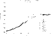
在第三试验期间取得的如图10a的所示的测量值代表固定在Xenobind玻璃载玻片上的兔的抗羊抗体的粘合层的折射率变化。如图10a所示,当建立了稳定的基准线时,将鼠IgG作为控制溶液加到贮器上,在此之后,监测折射率45分钟。和第一及第二试验的观察结果类似,添加非粘合鼠IgG控制溶液将导致折射率的立即变化,这是由于在包含鼠IgG的缓冲剂中的高盐浓度引起的。在折射率的立即变化后,折射率保持几乎不变历时45分钟。每45分钟向贮器相继添加对于抗体有特定亲合力的一定体积的50g/ml羊的IgG抗原。没有观察到折射率的立即阶跃,这是因为包含羊IgG抗原的缓冲剂等同于循环的接触溶液的缘故引起的。如图10a所示,一旦一定量的抗原加到接触相,就可检测到折射率的一个逐渐的变化,这表明抗原和固定的抗体之间的一种特定的粘合。通过使用线性回归拟合的图10b所示的数据还表明,折射率变化的速率随着抗原浓度的增加而增加。The measurements taken during the third experiment as shown in Figure 10a represent the change in the refractive index of the adhesive layer of rabbit anti-sheep antibody immobilized on a Xenobind glass slide. As shown in Figure 10a, when a stable baseline had been established, murine IgG was added to the reservoir as a control solution, after which the refractive index was monitored for 45 minutes. Similar to the observations of the first and second experiments, the addition of the non-binding mouse IgG control solution resulted in an immediate change in the refractive index due to the high salt concentration in the buffer containing the mouse IgG. After the immediate change in the refractive index, the refractive index remained almost unchanged for 45 minutes. A volume of 50 g/ml sheep IgG antigen having a specific affinity for the antibody was added sequentially to the reservoir every 45 minutes. No immediate step in the refractive index was observed because the buffer containing the sheep IgG antigen was equivalent to the circulating contact solution. As shown in Figure 10a, once a certain amount of antigen was added to the contact phase, a gradual change in the refractive index was detected, indicating a specific binding between the antigen and the immobilized antibody. The data shown in Figure 10b by fitting using linear regression also indicated that the rate of refractive index change increased with increasing antigen concentration.
在第四试验中,如以上所述,在一个Xenobind玻璃载玻片上固定羊的抗鼠IgG抗体。和第三实施例的结果类似,每当添加一定量的抗原时,折射计检测折射率变化。如图11a所示,在建立基准线后,将50g/ml的非粘合的羊IgG作为控制溶液加到贮器中。在添加了非抗原性的非粘合的羊IgG分子的情况下,没有观察到折射率的任何变化。还有,在大量添加牛血清清蛋白的情况下(没有表示出BSA数据)也没有观察到折射率的任何变化。然后,以大约25分钟的时间间隔并按10g/ml的增量向贮器添加鼠IgG抗原,所说的鼠IgG抗原对于抗鼠IgG抗体具有特定的亲合力。如图11a所示,折射率变化是相当大的并且是逐渐发生的,这和质量添加到接触相引起的折射率的立即变化的情况相反。和图10b中的数据类似,图11b中的用线性回归拟合的数据代表在基准线、控制溶液、和抗原添加物的测量期间由折射计检测到的折射率变化。就第三试验中羊IgG抗原的添加而论,在图11b中的折射率变化的速率随鼠IgG抗原的浓度的增加而增加。显然,这种逐渐增加是由粘合引起的,而不是由质量添加到接触相引起的。这种增加的幅度比由质量添加产生的增加幅度大得多。因此,图14a和14b中所示的由折射计检测到的折射率变化是由抗原/抗体粘合相互作用引起的。In a fourth experiment, goat anti-mouse IgG antibodies were immobilized on a Xenobind glass slide as described above. Similar to the results of the third example, the refractometer detected changes in the refractive index every time a certain amount of antigen was added. As shown in Figure 11a, after establishing the baseline, 50 g/ml of non-binding sheep IgG was added to the reservoir as a control solution. With the addition of non-antigenic, non-binding sheep IgG molecules, no change in the refractive index was observed. Also, no change in the refractive index was observed in the case of a large amount of bovine serum albumin added (BSA data not shown). Mouse IgG antigen, which has a specific affinity for anti-mouse IgG antibodies, is then added to the reservoir in increments of 10 g/ml at approximately 25 minute intervals. As shown in Figure 11a, the refractive index change is substantial and occurs gradually, as opposed to the immediate change in refractive index caused by mass addition to the contact phase. Similar to the data in Figure 10b, the data in Figure 11b fitted with a linear regression represent the changes in refractive index detected by the refractometer during the measurements of baseline, control solution, and antigen addition. Regarding the addition of goat IgG antigen in the third experiment, the rate of change of the refractive index in Figure lib increased with increasing concentration of murine IgG antigen. Apparently, this gradual increase is caused by adhesion, not by the addition of mass to the contacting phase. The magnitude of this increase is much greater than that produced by mass addition. Therefore, the refractive index changes detected by the refractometer shown in Figures 14a and 14b are caused by antigen/antibody binding interactions.
进行第五试验的目的是为了证实折射计检测和监视中性抗生物素蛋白结合的羊抗鼠抗体对于生物素化玻璃载玻片的粘合的能力。如图12所示,在基准线建立后,将15g/ml的中性抗生物素蛋白结合的羊抗鼠抗体加到贮器。在约40分钟并且折射率变化了0.002以后,折射率停止改变,这表明抗原/抗体粘合反应的饱和。由于折射率变化0.001对应于约1ng/mm2的固定的抗体,所以结合到载玻片表面的总的抗原/抗体是2ng/mm2或200ng/cm2。这样的结果完全在对于这种类型的实验所期望的范围之内。The purpose of the fifth experiment was to demonstrate the ability of the refractometer to detect and monitor the adhesion of neutravidin-conjugated goat anti-mouse antibody to biotinylated glass slides. As shown in Figure 12, after the baseline was established, 15 g/ml of neutravidin-conjugated goat anti-mouse antibody was added to the reservoir. After about 40 minutes and a change of 0.002 in the refractive index, the refractive index stopped changing, indicating saturation of the antigen/antibody binding reaction. Since a change in refractive index of 0.001 corresponds to about 1 ng/mm 2 of immobilized antibody, the total antigen/antibody bound to the slide surface is 2 ng/mm 2 or 200 ng/cm 2 . Such results are well within what would be expected for an experiment of this type.
在第六试验中,在一个生物素化玻璃载玻片上固定中性抗生物素蛋白结合的羊抗鼠抗体。其固定步骤以在载玻片的表面上涂抹稀释的抗体溶液并且培育3个小时,然后再将载玻片安装到折射计内而进行,从而可以防止中性抗生物素蛋白结合的羊抗鼠抗体非特定粘合到管道和贮器内。(当整个流动室设备未预先暴露到中性抗生物素蛋白结合的抗体时,随后的有关抗原的试验更加容易再现重复)。图13a表示的是在这个试验期间固定在载玻片上的中性抗生物素蛋白结合的羊抗鼠抗体的粘合层上的折射率变化。和以前的试验类似,使PBS基准线稳定,并且过量添加非粘合羊IgG控制溶液。如图13a所示,两次添加10g/ml的羊IgG控制溶液并没有使折射率产生任何变化。按另一种方式,添加一种BSA控制溶液(没有表示出BSA数据)。使控制溶液循环以保证随后观察到的折射率变化都是由于特定的抗原/抗体粘合相互作用引起的,而不是由于非特定的抗原/抗体粘合相互作用引起的。在IgG或BSA或两者组合的控制溶液存在的情况下,向贮器添加鼠IgG抗原。在PBS中还存在0.02%特威恩-20去污剂以便将非特定粘合减至最小。如图13a所示,在接触相中存在控制溶液与否,对于折射率几乎没有或根本没有影响。仅在先向贮器添加10g/ml而后添加20g/ml鼠IgG抗原时,折射率只发生逐渐的变化。由折射计检测和监视的这些变化再一次归因于特定的抗原/抗体粘合。图13b给出了代表折射率变化的拟合数据,它们对应于向贮器添加羊IgG控制溶液和两次添加抗原。再一次地,观察到的变化是由于抗原/抗体粘合相互作用引起的。In a sixth experiment, neutravidin-conjugated goat anti-mouse antibody was immobilized on a biotinylated glass slide. The fixation step is to apply a diluted antibody solution on the surface of the slide and incubate for 3 hours, and then install the slide into the refractometer, so as to prevent neutravidin-bound goat anti-mouse Antibodies bind non-specifically to tubing and reservoirs. (Subsequent assays with respect to antigen are more easily reproducible when the entire flow cell setup is not pre-exposed to neutravidin-conjugated antibody). Figure 13a shows the change in the refractive index of the adhesive layer of neutravidin-conjugated goat anti-mouse antibody immobilized on glass slides during this experiment. Similar to previous experiments, the PBS baseline was allowed to stabilize and a non-binding sheep IgG control solution was added in excess. As shown in Figure 13a, two additions of the 10 g/ml goat IgG control solution did not produce any change in the refractive index. Alternatively, a BSA control solution was added (BSA data not shown). The control solution was circulated to ensure that subsequently observed changes in refractive index were due to specific antigen/antibody binding interactions and not due to non-specific antigen/antibody binding interactions. Murine IgG antigen was added to the reservoir in the presence of a control solution of IgG or BSA or a combination of both. 0.02% Tween-20 detergent was also present in PBS to minimize non-specific binding. As shown in Figure 13a, the presence or absence of the control solution in the contact phase has little or no effect on the refractive index. Only gradual changes in the refractive index occurred when 10 g/ml and then 20 g/ml of murine IgG antigen were added to the reservoir. These changes detected and monitored by the refractometer were again attributed to specific antigen/antibody binding. Figure 13b presents the fitted data representing the change in refractive index corresponding to the addition of a goat IgG control solution to the reservoir and two additions of antigen. Again, the observed changes were due to antigen/antibody binding interactions.
第七试验的结果表示在图16a-16d中,第七试验与第六试验相同,只是100g/ml鼠IgG抗原添加到溶液以诱发响应。图16a表示在添加抗原之后接触相的折射率的变化。图16b说明第七试验期间强度随时间的变化。如图16b所示,阴影线的位置相对于仪器启地期间的阴影线位置(在图16b中分别为“G“和“B“)有所改变。图16c表示:在试验期间,响应于鼠IgG的添加,不仅阴影线的位置发生了改变,而且响应的强度也发生了改变。图16d表示出阴影线在试验开始时的位置(B)和在试验结束时的位置(G)。这些曲线表示:阴影线的位置和强度随鼠IgG向接触相的添加是如何变化的,以及在鼠IgG和固定在载玻片上的粘合层之间的粘合反应期间是如何变化的。The results of the seventh experiment are shown in Figures 16a-16d. The seventh experiment was identical to the sixth experiment except that 100 g/ml of murine IgG antigen was added to the solution to elicit a response. Figure 16a shows the change in the refractive index of the contacted phase after the addition of antigen. Figure 16b illustrates the change in intensity over time during the seventh trial. As shown in Figure 16b, the positions of the hatched lines are changed relative to the position of the hatched lines during the grounding of the instrument (respectively "G" and "B" in Figure 16b). Figure 16c shows that not only the position of the hatching changed but also the magnitude of the response in response to the addition of murine IgG during the test period. Figure 16d shows the positions of the hatched lines at the beginning of the test (B) and at the end of the test (G). These curves show how the position and intensity of the hatching changes with the addition of mouse IgG to the contact phase and how it changes during the adhesive reaction between the mouse IgG and the adhesive layer immobilized on the glass slide.
上述的试验表明,通过测量粘合层的折射率变化,就可以成功地使用临界角折射测量原理来检测和监视样品分析物和粘合层之间的粘合相互作用。下面根据这些试验结果,借助于例子描述本发明的方法和设备的几个实施例,这些例子不是对本发明的限制。我们的意图是,利用检测和监视各种配位体之间的粘合相互作用的临界角折射测量原理实施的其它实施方案都落在本发明的范围和构思之中。The experiments described above demonstrate that the principle of critical angle refractometry can be successfully used to detect and monitor the adhesive interaction between a sample analyte and the adhesive layer by measuring the change in the refractive index of the adhesive layer. Based on these test results, several embodiments of the method and apparatus of the present invention are described below by way of examples, which do not limit the invention. It is our intention that other embodiments implemented using the principle of critical angle refractometry to detect and monitor adhesive interactions between various ligands are within the scope and spirit of the present invention.
如以上所述,在自动折射率计Leica AR600的光学测量系统的示意图中(图4),来自光源48和光沿光路57行进,并以各种入射角照射棱镜50的上表面54。以大于临界角的角度入射在表面54上的光的一部分被反射回去,并且由LSA44检测。入射在表面54上的小于临界角的光的部分传送进样品51内并逸出LSA。可以使用相同的原理检测该设备的不同实施方案中的粘合相互作用,在所说的设备中光源48产生准直光束,这个准直光束以一个预定的入射角α入射在棱镜50的上表面54或其它任何检测表面上。例如,如果粘合层是直接淀积在棱镜50的表面54上,那么界面80将是表面54和粘合层之间的界面。按另一种方式,如果粘合层51′是淀积在透明盘78上,则界面80将是这个盘和粘合层之间的分界面。As described above, in the schematic diagram of the optical measurement system of the automatic refractometer Leica AR600 ( FIG. 4 ), light from the
例如,在图15a中示意表示的是由光源48产生的光束92,光束92以角度β1入射到界面80上。在该实施方案中光源48和传感器98的位置是预先确定的。如果在接触相59中存在对于粘合层51′具有特定亲合力的特定分析物,则要发生粘合,粘合层的折射率n2将要增加,而n1保持不变。由于n2增加,按照斯涅耳定律,全反射的临界角将增加。由于在所述的实施方案中入射角β1是固定的,选择入射角β1使其大于或等于在没有分析物结合到粘合层时的临界角,但小于当有分析物结合到粘合层时的临界角,这种选择将使光束92在无分析物结合的界面80上全反射,但在有分析物结合到这个粘合层时将使光束92穿过接触相透射出去。因此,当无分析物结合时,反射光束94将照射传感器98。一旦分析物结合到粘合层上,传感器98将检测不到反射光束94。如果实施方案的特定的方法和设计要求检测透射光,则可以定位另一个传感器(在图15a中用虚线表示)来检测透射光束96。通过用传感器98检测反射光束的存在,或者通过用其位置适合于检测透射光束的传感器(在图15a中用虚线表示)检测透射光束的存在,可以确定在粘合层和接触相中的分析物之间粘合相互作用存在与否。如果该实施方案使用了一个传感器,则在检测到光和检测不到光之间的过渡状态表示粘合。传感器98可以是一个简单的光检测器件,表示光束94(或光束96)是否照射到这个检测器件,传感器98或者可以是一个LSA,或者是任何其它的能够检测光的传感器。在本发明的这个实施方案中,在检测设备中用检测粘合相互作用来探测样品中是否存在特定物质。这种设备的一个例子是一种“是/否”测试设备,它能够指示在样品中是否存在特定类型的配位体(蛋白质、抗原、等)。例如,通过使用上述的测试设备实施方案,在家里的用户或实验室的工作人可分析血和尿的样品,看其中是否存在特殊物质。For example, shown schematically in FIG. 15a is a
在图15b中描述的本发明的另一个实施方案中,允许单个光源48移动,或者转动或者平动(在图15b中用箭头表示),从而改变了入射的准直光束92的轨迹,或者变为光束92a或者变为光束92b,借此改变了准直光束92的入射角(在图15b中用虚线表示)。和在图15a中描述的基础理论类似,当在分析物和粘合层51′之间的粘合发生时,n2增加,增加了全反射的临界角。如果初始的入射角大于或等于当没有分析物结合到粘合层时的全反射的临界角,则传感器98检测到反射光束94。当接触相59包含与粘合层反应的分析物时,则当粘合发生时,入射角不再满足全反射条件。通过移动或转动光源48,选择大于临界角的不同的角度(如β1),因而传感器98检测到反射光束94b。在这个实施方案中,传感器可以是LSA,但这不是必须的。像在图15a中所示的实施方案那样,或者检测反射光束94,或者检测透射光束96,都可以检测到粘合。光源可以是LED。In another embodiment of the invention depicted in FIG. 15b, a single
按另一种方式,代替移动或转动一个光源(图15a中的光源48),可使用多个固定的或可移动的光源49(图15c)引导光束以不同的入射角入射在界面80上。当由于分析物和粘合层51′之间的粘合使临界角增加时,可以引导来自于不同的光源48′的光束以较大的入射角β1入射到界面80上。如果入射角β1大于当分析物结合到粘合层时的全反射临界角,传感器98将通过检测反射光束94′来检测粘合。传感器98可以包括一个传感器,如LSA,或者包括多个传感器,如图15c中虚线所示的。Alternatively, instead of moving or rotating one light source (
还有一个设想是,当准直光束照射界面80时,如图18b和18c所示,代替移动或转动光源,可通过移动或转动其上固定有粘合层的透光元件来改变入射角以满足全内反射条件。Another idea is that when the collimated light beam irradiates the
可以理解,本发明包括用于检测和监视在各个配位体之间的粘合相互作用的设备和方法,为此要观察由于粘合引起的折射率随时间的变化。通过利用阴影线分析测量粘合层的全反射临界角的变化,可以观测到折射率变化。因此,使用非金属的透光元件来固定粘合层,借此可明显简化固定过程。况且,可以用相当低成本的仪器代替成本昂贵得多的SPR生物检测设备。因而,本发明可以节省技术人员的时间和设备投资。It will be appreciated that the present invention includes apparatus and methods for detecting and monitoring binding interactions between individual ligands by observing changes in refractive index over time due to binding. The change in refractive index can be observed by measuring the change in the critical angle of total reflection of the bonding layer using hatching analysis. Therefore, a non-metallic, light-transmitting element is used to fasten the adhesive layer, whereby the fastening process can be considerably simplified. Moreover, much more expensive SPR bioassay equipment can be replaced by a considerably lower cost instrument. Thus, the present invention can save technicians' time and equipment investment.
期望使用本发明来检测和监视各种各样的粘合相互作用,其中包括(但不限于);抗原/抗体、药物/受体、多核苷酸单链/互补的多核苷酸单链、抗生物素蛋白/生物素、免疫球蛋白/蛋白质A、酶/培养基、特定的碳水化合物/外源凝聚素等相互作用。测量输出可以是一个GO/NO GO报告的形式,例如通过LCD显示器38输出,这种测量输出在测试大肠杆菌或食物中含有的其它病原体的存在方面可能是有益的。本发明还可以提供诊断信息,诊断信息是通过酶连接的免疫吸附测定(ELISA)和放射免疫测定实时获得的。本发明的方法和设备可以在各种大小的设备中实施,其范围可以从手持式传感器到较大的工业用传感器系统。本发明的方法和设备的应用还包括检测和监视环境污染、农药、和代谢物,水质控制,药物的发现、研究、和制造,诊断化学物质的滥用,食品和饮料的加工。It is contemplated that the present invention can be used to detect and monitor a wide variety of adhesive interactions, including but not limited to; antigen/antibody, drug/receptor, polynucleotide single strand/complementary polynucleotide single strand, anti Biotin/Biotin, Immunoglobulin/Protein A, Enzyme/Medium, Specific Carbohydrate/Legrin, etc. interactions. The measurement output may be in the form of a GO/NO GO report, such as output via the
虽然这里已经说明并描述了特定的实施方案,但本领域的普遍技术人员应该理解,打算实现相同目的的任何设计都可以代替这里所示的特定实施方案。本申请旨在覆盖对于本发明的任何修改或变化。因此,明确表示希望:本发明只由下述的权利要求书限制。Although specific embodiments have been illustrated and described herein, it will be understood by those of ordinary skill in the art that any design which is intended to achieve the same purpose may be substituted for the specific embodiments shown. This application is intended to cover any adaptations or variations of the present invention. Accordingly, it is expressly intended that this invention be limited only by the following claims.
Claims (68)
Applications Claiming Priority (4)
| Application Number | Priority Date | Filing Date | Title |
|---|---|---|---|
| US10841498P | 1998-11-13 | 1998-11-13 | |
| US60/108414 | 1998-11-13 | ||
| US14220799P | 1999-07-02 | 1999-07-02 | |
| US60/142207 | 1999-07-02 |
Publications (2)
| Publication Number | Publication Date |
|---|---|
| CN1293757A CN1293757A (en) | 2001-05-02 |
| CN1237338C true CN1237338C (en) | 2006-01-18 |
Family
ID=26805867
Family Applications (1)
| Application Number | Title | Priority Date | Filing Date |
|---|---|---|---|
| CNB99803956XA Expired - Fee Related CN1237338C (en) | 1998-11-13 | 1999-11-12 | Refractometer and method for qualitative and quantitative measurements |
Country Status (8)
| Country | Link |
|---|---|
| US (2) | US6462809B1 (en) |
| EP (1) | EP1047929B1 (en) |
| JP (1) | JP3537767B2 (en) |
| CN (1) | CN1237338C (en) |
| AT (1) | ATE366414T1 (en) |
| AU (1) | AU1524500A (en) |
| DE (1) | DE69936442T2 (en) |
| WO (1) | WO2000029830A1 (en) |
Families Citing this family (79)
| Publication number | Priority date | Publication date | Assignee | Title |
|---|---|---|---|---|
| US8111401B2 (en) | 1999-11-05 | 2012-02-07 | Robert Magnusson | Guided-mode resonance sensors employing angular, spectral, modal, and polarization diversity for high-precision sensing in compact formats |
| US7167615B1 (en) | 1999-11-05 | 2007-01-23 | Board Of Regents, The University Of Texas System | Resonant waveguide-grating filters and sensors and methods for making and using same |
| US6594018B1 (en) * | 2000-02-01 | 2003-07-15 | Texas Instruments Incorporated | Miniature integrated multiple channel surface plasmon resonance liquid sensor |
| US7264973B2 (en) | 2000-10-30 | 2007-09-04 | Sru Biosystems, Inc. | Label-free methods for performing assays using a colorimetric resonant optical biosensor |
| US7118710B2 (en) | 2000-10-30 | 2006-10-10 | Sru Biosystems, Inc. | Label-free high-throughput optical technique for detecting biomolecular interactions |
| US7615339B2 (en) | 2000-10-30 | 2009-11-10 | Sru Biosystems, Inc. | Method for producing a colorimetric resonant reflection biosensor on rigid surfaces |
| US7023544B2 (en) | 2000-10-30 | 2006-04-04 | Sru Biosystems, Inc. | Method and instrument for detecting biomolecular interactions |
| US7575939B2 (en) | 2000-10-30 | 2009-08-18 | Sru Biosystems, Inc. | Optical detection of label-free biomolecular interactions using microreplicated plastic sensor elements |
| US7153702B2 (en) | 2000-10-30 | 2006-12-26 | Sru Biosystems, Inc. | Label-free methods for performing assays using a colorimetric resonant reflectance optical biosensor |
| US7142296B2 (en) | 2000-10-30 | 2006-11-28 | Sru Biosystems, Inc. | Method and apparatus for detecting biomolecular interactions |
| US7070987B2 (en) | 2000-10-30 | 2006-07-04 | Sru Biosystems, Inc. | Guided mode resonant filter biosensor using a linear grating surface structure |
| US7300803B2 (en) | 2000-10-30 | 2007-11-27 | Sru Biosystems, Inc. | Label-free methods for performing assays using a colorimetric resonant reflectance optical biosensor |
| US7306827B2 (en) | 2000-10-30 | 2007-12-11 | Sru Biosystems, Inc. | Method and machine for replicating holographic gratings on a substrate |
| US7217574B2 (en) | 2000-10-30 | 2007-05-15 | Sru Biosystems, Inc. | Method and apparatus for biosensor spectral shift detection |
| US7101660B2 (en) | 2000-10-30 | 2006-09-05 | Sru Biosystems, Inc. | Method for producing a colorimetric resonant reflection biosensor on rigid surfaces |
| US7175980B2 (en) | 2000-10-30 | 2007-02-13 | Sru Biosystems, Inc. | Method of making a plastic colorimetric resonant biosensor device with liquid handling capabilities |
| US6951715B2 (en) | 2000-10-30 | 2005-10-04 | Sru Biosystems, Inc. | Optical detection of label-free biomolecular interactions using microreplicated plastic sensor elements |
| US7202076B2 (en) | 2000-10-30 | 2007-04-10 | Sru Biosystems, Inc. | Label-free high-throughput optical technique for detecting biomolecular interactions |
| US7371562B2 (en) | 2000-10-30 | 2008-05-13 | Sru Biosystems, Inc. | Guided mode resonant filter biosensor using a linear grating surface structure |
| US6816248B2 (en) * | 2001-04-26 | 2004-11-09 | Reichert, Inc. | Hand-held automatic refractometer |
| US6710877B2 (en) * | 2001-07-23 | 2004-03-23 | Corning Incorporated | Apparatus and methods for determining biomolecular interactions |
| WO2003019182A1 (en) * | 2001-08-10 | 2003-03-06 | Roche Diagnostics Gmbh | Method for producing microparticles loaded with proteins |
| US7187444B2 (en) | 2001-11-12 | 2007-03-06 | Fuji Photo Film Co., Ltd. | Measuring method and apparatus using attenuation in total internal reflection |
| US20050003459A1 (en) * | 2002-01-30 | 2005-01-06 | Krutzik Siegfried Richard | Multi-purpose optical analysis disc for conducting assays and related methods for attaching capture agents |
| US6734956B2 (en) * | 2002-05-06 | 2004-05-11 | Reichert, Inc. | Optical configuration and method for differential refractive index measurements |
| US6816254B2 (en) | 2002-07-29 | 2004-11-09 | Richert, Inc. | Flow cell clamp |
| US7429492B2 (en) | 2002-09-09 | 2008-09-30 | Sru Biosystems, Inc. | Multiwell plates with integrated biosensors and membranes |
| US6885455B2 (en) * | 2002-11-22 | 2005-04-26 | Dwight U. Bartholomew | Self-calibration of an optical-based sensor using a total internal reflection (TIR) signature |
| US20040228766A1 (en) * | 2003-05-14 | 2004-11-18 | Witty Thomas R. | Point of care diagnostic platform |
| WO2004104554A2 (en) * | 2003-05-20 | 2004-12-02 | Technology Innovations, Llc | Organic analysis module |
| US20050118728A1 (en) * | 2003-07-02 | 2005-06-02 | Caldwell Kevin K. | Two-layer antibody capture system |
| US20050046848A1 (en) * | 2003-08-26 | 2005-03-03 | Blueshift Biotechnologies, Inc. | Time dependent fluorescence measurements |
| WO2005052644A2 (en) * | 2003-11-21 | 2005-06-09 | Perkinelmer Las, Inc. | Optical device integrated with well |
| JP2005156415A (en) * | 2003-11-27 | 2005-06-16 | Aisin Seiki Co Ltd | Surface plasmon resonance sensor |
| WO2005065157A2 (en) * | 2003-12-23 | 2005-07-21 | Fastraq, Inc. | Point of care diagnostic platform |
| US20050148063A1 (en) * | 2003-12-24 | 2005-07-07 | Cracauer Raymond F. | Disposable reaction vessel with integrated optical elements |
| WO2005067651A2 (en) * | 2004-01-08 | 2005-07-28 | Cappo Anthony P | Surface plasmon resonance based nanoliter tear osmometer |
| US20050267346A1 (en) * | 2004-01-30 | 2005-12-01 | 3Wave Optics, Llc | Non-invasive blood component measurement system |
| US20050264805A1 (en) * | 2004-02-09 | 2005-12-01 | Blueshift Biotechnologies, Inc. | Methods and apparatus for scanning small sample volumes |
| US7271885B2 (en) * | 2004-03-25 | 2007-09-18 | Perkinelmer Las, Inc. | Plasmon resonance measuring method and apparatus |
| EP1774024A4 (en) | 2004-07-02 | 2012-04-04 | Blueshift Biotechnologies Inc | Exploring fluorophore microenvironments |
| WO2006022277A1 (en) * | 2004-08-24 | 2006-03-02 | Fujifilm Corporation | Method for calculating dissociation constant in surface plasmon resonance analysis |
| KR20070107759A (en) * | 2005-02-11 | 2007-11-07 | 스와겔로크 컴패니 | Fluid concentration sensing device |
| US8094314B2 (en) * | 2005-10-21 | 2012-01-10 | The Regents Of The University Of California | Optical sensing based on surface plasmon resonances in nanostructures |
| US7445934B2 (en) * | 2006-04-10 | 2008-11-04 | Baker Hughes Incorporated | System and method for estimating filtrate contamination in formation fluid samples using refractive index |
| US8431088B2 (en) | 2006-09-25 | 2013-04-30 | Covidien Lp | Carbon dioxide detector having borosilicate substrate |
| US8128574B2 (en) | 2006-09-25 | 2012-03-06 | Nellcor Puritan Bennett Llc | Carbon dioxide-sensing airway products and technique for using the same |
| US8431087B2 (en) | 2006-09-25 | 2013-04-30 | Covidien Lp | Carbon dioxide detector having borosilicate substrate |
| US8420405B2 (en) | 2006-09-25 | 2013-04-16 | Covidien Lp | Carbon dioxide detector having borosilicate substrate |
| US8449834B2 (en) | 2006-09-25 | 2013-05-28 | Covidien Lp | Carbon dioxide detector having borosilicate substrate |
| US8396524B2 (en) | 2006-09-27 | 2013-03-12 | Covidien Lp | Medical sensor and technique for using the same |
| US9134307B2 (en) | 2007-07-11 | 2015-09-15 | X-Body, Inc. | Method for determining ion channel modulating properties of a test reagent |
| CN101802611A (en) | 2007-07-11 | 2010-08-11 | Sru生物系统公司 | Methods of identifying modulators of ion channels |
| DE102007033124B4 (en) * | 2007-07-16 | 2012-12-06 | Fraunhofer-Gesellschaft zur Förderung der angewandten Forschung e.V. | Device for the optical detection of substances in a liquid or gaseous medium |
| CN101836102B (en) * | 2007-10-25 | 2012-02-29 | 皇家飞利浦电子股份有限公司 | Sensor device for target particles in a sample |
| WO2009137122A2 (en) * | 2008-02-01 | 2009-11-12 | Rare Light, Inc. | Methods, devices and kits for peri-critical reflectance spectroscopy |
| US20090279076A1 (en) * | 2008-05-09 | 2009-11-12 | Board Of Regents, The University Of Texas System | Self calibrated measurement of index of refraction changes to ultra-fast phenomena |
| US20090323073A1 (en) * | 2008-06-30 | 2009-12-31 | Reichert, Inc. | Analytical Instrument Having Internal Reference Channel |
| TW201009316A (en) * | 2008-08-29 | 2010-03-01 | Univ Nat Taiwan | Surface plasmon resonance meter |
| CA2758113A1 (en) | 2009-04-07 | 2010-10-14 | Rare Light, Inc. | Peri-critical reflection spectroscopy devices, systems, and methods |
| WO2010135417A2 (en) | 2009-05-22 | 2010-11-25 | 3M Innovative Properties Company | Multilayer colorimetric sensor arrays |
| JP5669449B2 (en) * | 2009-06-26 | 2015-02-12 | メトラー−トレド アクチェンゲゼルシャフト | Refractometer |
| CN102253005A (en) * | 2011-04-15 | 2011-11-23 | 深圳大学 | Surface plasmon resonance sensing detection system and method |
| US8970838B2 (en) | 2011-04-29 | 2015-03-03 | Avolonte Health LLC | Method and apparatus for evaluating a sample through variable angle Raman spectroscopy |
| US8989232B2 (en) | 2012-08-23 | 2015-03-24 | The Regents Of The University Of California | Nanoscale coaxial lasers |
| CN102944537B (en) * | 2012-10-23 | 2016-04-06 | 深圳大学 | A kind of detection system based on SPR and detection method thereof |
| EP2966482B1 (en) * | 2013-03-08 | 2023-03-01 | National Yang-Ming University | Prism and optical detection system applying same |
| US10281553B2 (en) | 2013-03-15 | 2019-05-07 | Leap Motion, Inc. | Determining the orientation of objects in space |
| RU2563543C2 (en) * | 2014-01-31 | 2015-09-20 | Акционерное общество "Швабе - Технологическая лаборатория" (АО "Швабе-Технологическая лаборатория") | Method and device to measure refraction index |
| JP6683126B2 (en) * | 2014-06-02 | 2020-04-15 | コニカミノルタ株式会社 | Method of manufacturing detection chip |
| CN104792733B (en) * | 2015-04-04 | 2017-05-17 | 华中科技大学 | Quick calibration module and application |
| CN109073539A (en) * | 2016-05-03 | 2018-12-21 | 文塔纳医疗系统公司 | System and method for monitoring reagent concentration |
| CN106404719B (en) * | 2016-08-25 | 2018-07-10 | 安阳师范学院 | Method based on surface plasmon resonance detection protein kinase |
| WO2019176157A1 (en) * | 2018-03-15 | 2019-09-19 | 三菱電機株式会社 | Biological material measurement device |
| CN108489936B (en) * | 2018-04-08 | 2024-03-19 | 吉林省富生医疗器械有限公司 | Household cystatin C concentration rapid tester and testing method thereof |
| FI20205546A1 (en) * | 2020-05-27 | 2021-11-28 | Kxs Tech Oy | An optically transparent window assembly for detachable connection to a refractometer |
| US20240118200A1 (en) * | 2020-12-08 | 2024-04-11 | Arizona Board Of Regents On Behalf Of Arizona State University | Critical angle reflection imaging for quantification of molecular interactions |
| US20230129832A1 (en) * | 2021-10-22 | 2023-04-27 | Terumo Bct, Inc. | Method And System For Determining Plasma Protein Content Of Whole Blood Using Refractometry |
| US11486825B1 (en) * | 2022-06-07 | 2022-11-01 | The Florida International University Board Of Trustees | Devices and methods for analysis of biological matter using plasmon resonance |
Family Cites Families (38)
| Publication number | Priority date | Publication date | Assignee | Title |
|---|---|---|---|---|
| US3612696A (en) | 1969-01-21 | 1971-10-12 | Phillips Petroleum Co | Refractometer |
| US3778165A (en) | 1971-05-24 | 1973-12-11 | Hamilton Co | Portable flow-through dispensing refractometer apparatus |
| US4286873A (en) | 1979-06-25 | 1981-09-01 | Waters Associates, Inc. | Refractometer cell with integral lens |
| US4381895A (en) | 1980-02-28 | 1983-05-03 | Biovation, Inc. | Method and apparatus for automatic flow-through digital refractometer |
| US4640616A (en) | 1984-12-06 | 1987-02-03 | The Cambridge Instrument Company Plc | Automatic refractometer |
| WO1986007149A1 (en) | 1985-05-29 | 1986-12-04 | Kurt Tiefenthaler | Optical sensor for selectively determining the presence of substances and the variation of the refraction index in the measured substances |
| US4844869A (en) * | 1985-09-09 | 1989-07-04 | Ord, Inc. | Immunoassay apparatus |
| US4909990A (en) | 1987-09-02 | 1990-03-20 | Myron J. Block | Immunoassay apparatus |
| US5478755A (en) | 1988-07-25 | 1995-12-26 | Ares Serono Research & Development Ltd. | Long range surface plasma resonance immunoassay |
| SE462408B (en) | 1988-11-10 | 1990-06-18 | Pharmacia Ab | OPTICAL BIOSENSOR SYSTEM USING SURFACE MONITORING RESONSE FOR THE DETECTION OF A SPECIFIC BIOMOLIC CYCLE, TO CALIBRATE THE SENSOR DEVICE AND TO CORRECT FOUND BASELINE OPERATION IN THE SYSTEM |
| GB8827853D0 (en) * | 1988-11-29 | 1988-12-29 | Ares Serono Res & Dev Ltd | Sensor for optical assay |
| GB8913474D0 (en) | 1989-06-12 | 1989-08-02 | Amersham Int Plc | Assay method |
| WO1992003720A1 (en) | 1990-08-17 | 1992-03-05 | Fisons Plc | Analytical device |
| US5167149A (en) | 1990-08-28 | 1992-12-01 | Schlumberger Technology Corporation | Apparatus and method for detecting the presence of gas in a borehole flow stream |
| US5377008A (en) | 1990-09-20 | 1994-12-27 | Battelle Memorial Institute | Integrated optical compensating refractometer apparatus |
| US5192510A (en) | 1991-01-30 | 1993-03-09 | E. I. Du Pont De Nemours And Company | Apparatus for performing fluorescent assays which separates bulk and evanescent fluorescence |
| GB9102646D0 (en) | 1991-02-07 | 1991-03-27 | Fisons Plc | Analytical device |
| GB9111912D0 (en) | 1991-06-04 | 1991-07-24 | Fisons Plc | Analytical methods |
| EP0517930B1 (en) | 1991-06-08 | 1995-05-24 | Hewlett-Packard GmbH | Method and apparatus for detecting the presence and/or concentration of biomolecules |
| SE9201984D0 (en) | 1992-06-29 | 1992-06-29 | Pharmacia Biosensor Ab | IMPROVEMENT IN OPTICAL ASSAYS |
| US5494829A (en) | 1992-07-31 | 1996-02-27 | Biostar, Inc. | Devices and methods for detection of an analyte based upon light interference |
| US5680209A (en) | 1992-08-13 | 1997-10-21 | Maechler; Meinrad | Spectroscopic systems for the analysis of small and very small quantities of substances |
| DE4227813A1 (en) | 1992-08-21 | 1994-02-24 | Kim Yoon Ok | Device for the qualitative and / or quantitative determination of a sample to be analyzed |
| DE69321191T2 (en) | 1992-11-17 | 1999-04-29 | Hoechst Ag, 65929 Frankfurt | Optical sensor for the detection of chemical species |
| DE59410197D1 (en) | 1993-03-26 | 2002-11-21 | Hoffmann La Roche | Optical method and device for analyzing substances on sensor surfaces |
| SE501108C2 (en) | 1993-04-08 | 1994-11-14 | Pharmacia Lkb Biotech | Method and apparatus for determining refractive index |
| JP3157952B2 (en) | 1993-06-02 | 2001-04-23 | アヴェンティス・リサーチ・ウント・テクノロジーズ・ゲーエムベーハー・ウント・コー・カーゲー | Optical sensor for chemical substance detection |
| US5422714A (en) | 1993-06-07 | 1995-06-06 | Corning Incorporated | Device for comparing the refractive indices of an optical immersion liquid and a reference glass |
| FI933830A0 (en) * | 1993-09-01 | 1993-09-01 | Janesko Oy | REFRACTORY MEASUREMENT |
| US5712705A (en) | 1993-11-15 | 1998-01-27 | Carl Zeiss Jena Gmbh | Arrangement for analysis of substances at the surface of an optical sensor |
| US5538850A (en) | 1994-04-15 | 1996-07-23 | Hewlett-Packard Company | Apparatus and method for intracavity sensing of microscopic properties of chemicals |
| US5485277A (en) * | 1994-07-26 | 1996-01-16 | Physical Optics Corporation | Surface plasmon resonance sensor and methods for the utilization thereof |
| US5633724A (en) * | 1995-08-29 | 1997-05-27 | Hewlett-Packard Company | Evanescent scanning of biochemical array |
| US5639668A (en) | 1995-09-14 | 1997-06-17 | Boehringer Mannheim Corporation | Optical apparatus for performing an immunoassay |
| AU7598996A (en) | 1995-10-25 | 1997-05-15 | University Of Washington | Surface plasmon resonance probe systems based on a folded planar lightpipe |
| US5854863A (en) | 1996-03-15 | 1998-12-29 | Erb; Judith | Surface treatment and light injection method and apparatus |
| US6097479A (en) | 1996-10-01 | 2000-08-01 | Texas Instruments Incorporated | Critical angle sensor |
| DE69830529T2 (en) | 1997-02-07 | 2006-05-11 | Fuji Photo Film Co., Ltd., Minami-Ashigara | Surface plasmon sensor |
-
1999
- 1999-11-12 DE DE69936442T patent/DE69936442T2/en not_active Expired - Fee Related
- 1999-11-12 EP EP99957564A patent/EP1047929B1/en not_active Expired - Lifetime
- 1999-11-12 CN CNB99803956XA patent/CN1237338C/en not_active Expired - Fee Related
- 1999-11-12 AT AT99957564T patent/ATE366414T1/en not_active IP Right Cessation
- 1999-11-12 US US09/439,876 patent/US6462809B1/en not_active Expired - Fee Related
- 1999-11-12 AU AU15245/00A patent/AU1524500A/en not_active Abandoned
- 1999-11-12 JP JP2000582784A patent/JP3537767B2/en not_active Expired - Fee Related
- 1999-11-12 WO PCT/US1999/026981 patent/WO2000029830A1/en not_active Ceased
-
2002
- 2002-10-07 US US10/266,170 patent/US20030112427A1/en not_active Abandoned
Also Published As
| Publication number | Publication date |
|---|---|
| US20030112427A1 (en) | 2003-06-19 |
| EP1047929B1 (en) | 2007-07-04 |
| DE69936442D1 (en) | 2007-08-16 |
| JP2002530643A (en) | 2002-09-17 |
| EP1047929A4 (en) | 2004-12-15 |
| EP1047929A1 (en) | 2000-11-02 |
| CN1293757A (en) | 2001-05-02 |
| JP3537767B2 (en) | 2004-06-14 |
| DE69936442T2 (en) | 2008-04-17 |
| WO2000029830A1 (en) | 2000-05-25 |
| US6462809B1 (en) | 2002-10-08 |
| AU1524500A (en) | 2000-06-05 |
| WO2000029830A9 (en) | 2000-11-09 |
| ATE366414T1 (en) | 2007-07-15 |
Similar Documents
| Publication | Publication Date | Title |
|---|---|---|
| CN1237338C (en) | Refractometer and method for qualitative and quantitative measurements | |
| US9829434B2 (en) | Optical detection system for liquid samples | |
| Beusink et al. | Angle-scanning SPR imaging for detection of biomolecular interactions on microarrays | |
| EP0519622A2 (en) | Evanescent wave sensor shell and apparatus | |
| CN108474741A (en) | The optical detection of particle in fluid | |
| JP2007501403A (en) | Optical fiber array biochip based on spectral change rule of white light reflection interference | |
| JP2005509158A (en) | Microchip type enzyme-linked immunosorbent assay (ELISA) concentration measuring apparatus and concentration measuring method | |
| US7470549B2 (en) | Measurement method using biosensor | |
| JP2004125748A (en) | Sensor | |
| US7563624B2 (en) | Measurement method using biosensor | |
| EP1628126A2 (en) | Method for measuring reaction rate coefficient by surface plasmon resonance | |
| JP7362336B2 (en) | Methods for detecting or quantifying analytes in specimens, methods for stirring reaction mixtures, methods for causing flow in liquid media, additives, reagents, and automated analytical equipment. | |
| JP4292043B2 (en) | Measuring chip used for surface plasmon resonance measuring device | |
| JP4369295B2 (en) | Measuring method using biosensor | |
| US20200057056A1 (en) | Method of detecting or quantifying detection target in specimen, method of agitating reaction mixture, method of causing flow of liquid medium, additive, reagent, and automatic analyzing apparatus | |
| JP2005164371A (en) | Method of measuring surface plasmon resonance | |
| WO2024187107A1 (en) | Instruments and methods for performing optical assays | |
| WO2025015033A1 (en) | Reflection-reducing well plate | |
| WO2006028174A1 (en) | Measuring equipment and measuring method | |
| JP2005164372A (en) | Method of measuring surface plasmon resonance | |
| JP2006078212A (en) | Surface plasmon resonance measuring method | |
| JP2006234706A (en) | Biosensor | |
| JP2006058037A (en) | Measuring method of rate coefficient of desorption in surface plasmon resonance analysis | |
| Salina | Development of fluoropolymer based biosensor for the optical detection of biomolecular interactions | |
| WO2005001476A1 (en) | Method of preparing array |
Legal Events
| Date | Code | Title | Description |
|---|---|---|---|
| C06 | Publication | ||
| PB01 | Publication | ||
| C10 | Entry into substantive examination | ||
| SE01 | Entry into force of request for substantive examination | ||
| C14 | Grant of patent or utility model | ||
| GR01 | Patent grant | ||
| ASS | Succession or assignment of patent right |
Owner name: RIKET CO., LTD. Free format text: FORMER OWNER: LEICA MICROSYSTEMS INC. Effective date: 20060317 |
|
| C41 | Transfer of patent application or patent right or utility model | ||
| TR01 | Transfer of patent right |
Effective date of registration: 20060317 Address after: American New York Patentee after: Reichert Inc. Address before: American New York Patentee before: Leka Microsystem Co. |
|
| C19 | Lapse of patent right due to non-payment of the annual fee | ||
| CF01 | Termination of patent right due to non-payment of annual fee |