CN1232718C - Electrical heater - Google Patents
Electrical heater Download PDFInfo
- Publication number
- CN1232718C CN1232718C CN 99102078 CN99102078A CN1232718C CN 1232718 C CN1232718 C CN 1232718C CN 99102078 CN99102078 CN 99102078 CN 99102078 A CN99102078 A CN 99102078A CN 1232718 C CN1232718 C CN 1232718C
- Authority
- CN
- China
- Prior art keywords
- heating element
- heater
- well
- element structure
- heating
- Prior art date
- Legal status (The legal status is an assumption and is not a legal conclusion. Google has not performed a legal analysis and makes no representation as to the accuracy of the status listed.)
- Expired - Fee Related
Links
Images


Classifications
-
- E—FIXED CONSTRUCTIONS
- E21—EARTH DRILLING; MINING
- E21B—EARTH DRILLING, e.g. DEEP DRILLING; OBTAINING OIL, GAS, WATER, SOLUBLE OR MELTABLE MATERIALS OR A SLURRY OF MINERALS FROM WELLS
- E21B36/00—Heating, cooling, insulating arrangements for boreholes or wells, e.g. for use in permafrost zones
- E21B36/04—Heating, cooling, insulating arrangements for boreholes or wells, e.g. for use in permafrost zones using electrical heaters
Abstract
A heater is disclosed which comprises an electrical insulating material surrounding an annular heating element configuration; wherein there is no casing surrounding an annular heating element configuration.
Description
Technical field
The present invention relates to a kind of electrical heating method and device that is applicable to well (Borehole).
Background of invention
United States Patent (USP) N0.4640352 and No.4886118 disclose that low-permeable subsurface structure to oil-containing carries out conductive heater so that recovered oil therefrom.The low-permeable structure comprises kieselguhr, lipoid coal and oil shale.The low-permeable structure is for example used steam, carbon dioxide or fiery overflow (Flooding) and bad for the secondary oil absorption method.Overflow material preferentially penetrates from the fracture with low-permeable structure.The material that injects is walked around most hydrocarbons.In contrast, conductive heater does not need fluid input structure.Therefore oil in the structure needn't be walked around in flooding process.Heat is injected well and then is used for providing heat energy in this process.
Heat is injected well and also be can be used for purifying soil.For example U.S. Patent No. 5318116 and No.5244310 disclose the certain methods that purifies soil, wherein, heat energy are injected under the soil surface so that make the pollutant evaporation.The heater of patent ' 310 uses resistor rod, and electric current imports soil into by resistor rod.Patent ' 116 disclose delivers to the bottom that is heated structure with heating element through well.Well around heater comprises a catalyst bed (Catalyst bed), and this catalyst bed is heated the element heating.Conduction of heat is radiated soil on every side by cover again through the cover (Casing) of catalyst bed arrival around catalyst bed.Typical alum clay base catalyst bed has very low heat conductivity, and has great temperature gradient in catalyst bed.This huge temperature gradient will cause at limited temp of heating element, reduce being heated the heat transmission of soil.
U.S. Patent No. 5065818 discloses a kind of heater well, and this heater well has sheath and ore insulation (" MI ") heating cable, and this cable directly is bonded in the well.The MI cable comprises heating element, and this heating element is by for example magnesia encirclement of insulating layer, and the sheath that has one deck to approach is enclosed within outside the insulating layer.The external diameter of heating cable is in typical case less than half inch (1.25cm).Heater well is provided with a passage alternatively, is used for putting next thermocouple through the well of cementing, with the Temperature Distribution of record heated well.Owing to be directly to cement, no longer need to add cover (not being meant the sheath of cable outside), but the external diameter of cable is less in well.The less external diameter of heating cable has limited and can pass to heat in the structure by cable, because must be restricted through its cable area that transmits heat.The cement well has lower heat conductivity, therefore, in the bigger heat flux of cable surface, can make that the temperature of heater cable is too high and can not accept.A plurality of heater cables can be bonded in the well with increase to above-mentioned can only be with the heat transmission of the structure of a cable, but, this will be desirable for the heat that further increase can be delivered in the heater surrounding soil.
U.S. Patent No. 2732195 discloses a kind of electric heater well, and wherein, with a kind of " resistance powder " material, preferably the quartz of quartz sand or pulverizing is placed on the outer and both sides of well heaters set, and is looped around the electrical heating elements in the cover.
Summary of the invention
Therefore, one object of the present invention is to provide a kind of well heater, and wherein, heater has surface area bigger than prior art under serviceability temperature, and, no longer need cover in essence.This heater is useful as a kind of well heater that is used for such as hydrocarbon heat utilization or soil transformation.
These purposes and other purposes realize that by a kind of well heater it comprises: an annular heating element structure; With an insulating material, it is around annular heating element structure; Wherein, around the sleeve pipe of annular heating element structure, not it is characterized in that: annular heating element structure comprises a plate that extends at least, and this buttress curves circular arc according to the part of well bore wall.
Nothing cover heater design of the present invention greatly reduces the cost that heat is injected well, and this is for using hot injection method, and is from such as the application of reclaiming hydrocarbon oil shale, Tar sands or the kieselguhr, significant.Heat is injected and also can be used to remove many pollutants.
Best annular heating element structure is to select from a kind of assembly, and this assembly comprises an annular expanded metal, the metal sheet of one or more extensions, and one or more gauzes are with the band that is linked to each other by division board, rod or filament.
According to a further aspect in the invention, provide a kind of method that is used to heat a part of stratum, this method comprises the steps:
In the stratum of preparing heating, a well is set;
In well, place an annular heating element structure; With
In well, support heating element structure with electric insulation element, wherein, do not place metallic sheath at heating element structure with between the soil of preparing to heat.
Brief description of drawings
Fig. 1 shows according to the first embodiment of the present invention, the heater in well.
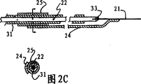
Fig. 2 A, 2B and 2C show the details that is installed in the cable at heater top according to the present invention.
Fig. 3 shows according to another embodiment of the present invention, the heater in well.
Fig. 4 shows the drawing in side sectional elevation of the heater in well shown in Figure 3.
Fig. 5 shows the device that is used to install according to heater of the present invention.
Detailed description of preferred embodiment
The ring heater that the present invention can select has a kind of grid heating element, can be made into to make its shape that is suitable for well bore wall, and the surface of the feasible heating element that is provided heat flux big as far as possible and that leave from well is big as far as possible.A kind of electrical insulation filler around placement, has been eliminated heating element in essence and has been heated electric short circuit between the structure in heating element.This insulating material can wet in its original state, therefore conducts electricity before its drying.Drying stage can be finished by switching on to wet stock through heating element, and the heat that electric energy produced can heat soil gradually and finally make unborn aqueous water evaporation.Remaining dry sand is a kind of acceptable electrical insulation.The suction of cement has reduced the aqueous water of free state, and the cement after the maintenance can be a kind of acceptable electrical insulators.Some other material can be used as isolator.Preferably place easily and not expensive material.Desirable material both can be or become non-conducting material easily.A kind of material, sand for example can pneumatically spurts or places as a kind of mud.
Preferably a plurality of electrical heating elements are placed in the well to form heater, this element is connected the bottom of well, and the not homophase of AC power is connected with each element.Two to three elements preferably.
Heating element can be the metal that extends, perhaps other porous metals element line screen (Wirescreen) or gauze for example.Porosity (Porosity) is preferably in 80 40 percent to percent; Here, porosity is defined as, the shared percentage of being seen on metal sheet of empty area.By this empty area is provided, increase the gross area that contacts with heating element greatly.Thicker element provides bigger corrosion allowance.The selection of the thickness of heating element is a target with the too high or too low voltage requirements of the unlikely proposition of heat flux.For example, in well, about 120 volts to about 960 volts of the AC voltage difference between two heating elements upper ends and its lower end that is connected.Generally, for long distance (100 to 700 meters), voltage difference is recommended as 480 to 960 volts, and for than short distance (2 to 200 meters), voltage difference is recommended as 120 to 480 volts.The heating element that be to adapt to big thickness can be with a plurality of heaters series connection, but its aperture ranges is subjected to being connected to the restriction of the cable expense of heating element.Preferably power supply being received the clean voltage difference that makes on the symmetrical heating element therebetween is zero.Like this, at a time being applied to the voltage on the electrode, is negative with respect to the ground wire that is applied to other heating element voltages.
Heating element is preferably made curve shape, perhaps the surface or in well to adapt to the wall of well.Curve shape can obtain on the surface by the pattern tool, passes through this mould when the metal of making heating element is put into well.Curve shape also can use an axle to obtain by this element in well.This axle for example can be used as an a kind of part of device, this device with each element separately, and with the electrical insulation material around each element, and between each element.When heating element is made curve shape on its surface, can add centralizer and division board at heating element, in well so that each element is separated.It is best using above-mentioned axle, because no longer need division board and centering device, has reduced Master Cost.Plain net lattice element also may adopt.Adopt the advantage of shaped form element to be, heat can be from the almost whole circumference transmission of well, and uses two plate-shaped elements, can have only about twice of borehole diameter from the area of its heat transfer, but, plate-shaped element being installed may be simple than semi-circle shaped elements is installed.
Generally, use stainless steel, for example 304 or 316, the heating element of making is best.INCLOY600 also can use (INCLOY is a kind of trade mark).When heating element will be exposed in the salt solution, preferably use 316 stainless steels, because 316 stainless steels have the ability of resisting chlorides corrosion preferably.Stainless steel is also not really expensive, and can stand the sort ofly from starting to the long-time exposure that element is reached a high temperature, and under most borehole environments, has enough low rate of corrosion during hot soak condition.Generally make heating element without stainless steel, because its resistance to high temperature corrosion is limited in one's ability, still, because the surface area that heater of the present invention conducts heat is bigger, the temperature of heater surfaces can be suitable for stainless steel.Carbon steel also can be used for not requiring the heating element that the high level heating is provided for a long time.
Though a preferred embodiment of the present invention comprises uses stainless steel as the heating element material, high alloy material may use in some application of the present invention.For example, when heater is used for darker well, the cost that provides the cost of deep-well to be much higher than the heating element material, and high alloy material is owing to allow in higher temperature work, thereby reduce for the needed well number of same heat requirement, this just might reduce total cost.
In addition, heating element can cover the more erosion-resisting metal surface of one deck, or one deck refractive surface is to provide extra electrical insulation and protection.
The thermocouple of control heater can be arranged in the well, or within the shaped form heating element, or outside heating element, or attached to (connecting by a kind of electrical insulation) on the heater.Thermocouple can monitor operation, or the power supply of control heater element.When thermocouple is used to control power supply, can use a plurality of thermocouples, the control temperature is selected from thermocouple.The selection of temperature can be based on maximum temperature, two to three kinds of temperature that average temperature or a kind of integrated temperature are for example the highest average.
Heating element of the present invention can be made into has wide length range, and this is owing to select the different voltage and the multifarious cause of the porous combination of heating element.The heater that is short to two to six meters may use, and the heater that reaches 200 to 700 meters also can provide.
In well, wherein placed heater of the present invention, on heater, at least and the part of eye may tubing and cement, to guarantee to be heated the insulation of structure.In shallow well, well may filling with sand until the surface.
Referring now to Fig. 1,, the figure shows the schematic diagram of ring heater of the present invention.A kind of grid type heating element 1 as shown is the semicircle metal sheet that extends, in well 2, electrical insulation filler 3, sand for example, as shown in the figure around and between heating element.Well is positioned at and is heated among the soil 4, and this soil may be kieselguhr oil-bearing structure, Tar sands or oil shale.In addition, this soil that will heat 4 may be to analyse contaminated soil in the transformation process in pyrolysis.Electric wire 5 extends to each heating element, is electrically connected in the heater bottom with connecting line 6 between the heating element.Each heating element all can be borehole bottom ground connection in addition.Electric wire passes the table soil covering layer 7 that is not subjected to heat and extends, and is by sheath cable 8, and the sheath cable is separated by division board 9.The transition part of well will be heated by the heater element, but can not reach that part of temperature that contains heating element in the well.The transition part of this well is added sleeve pipe with sleeve pipe 10 as shown in the figure, and this sleeve pipe available metal for example stainless steel is made, and it will have acceptable long-term useful life longevity under the condition of high temperature.Environmental corrosion in this transition part may be than more serious near the environmental corrosion at heater place, because dewpoint temperature is in this zone.On transition region, sleeve pipe may be with carbon steel sleeve pipe 11.At transition region and the native covering layer 7 of table, can fill in the sleeve pipe with filler 12 for example sand, cement, or still empty.
Referring now to Fig. 2 A,, 2B and 2C, the build-up member that the view of three band partial cutaway has been represented cable of the present invention with being connected of heating element.The top 21 of heating element is connected with high-temperature cable 22 by pad 33.Waterproof interface between cable and heater A is in the transition region.Can use for example copper electric wire of polyethylene covering of a kind of not expensive cable on the transition region.The high-temperature portion B of electrical insulation extends to heating element from anti-water termination.Bracing piece 24 provides the support between electric connecting point and heating element.Bracing piece is to be installed on the cable by the collar 25.The collar is a kind of electrical insulation collar.Anti-water termination comprises connector 26, is looped around a soft soldering tie point 27 outsides, and this soft soldering tie point provides the continuity between high-temperature cable 22 and the cryocable 28.Connector is to be screwed into union assembly 30 with spiral, and this assembly can be the brass assembly, and provides a kind of frictional fit to high-temperature cable sheath 31 and cryocable sheath 23.Cable 23 from the surface up to the heater top, the mining insulated cable of available copper core-copper sheathing.This class cable is best, because the very big electric current of its available conductive, and be waterproof.Though cable can stand high temperature, owing to consider rate of corrosion, the following temperature of the boiling point of Ying Zaishui is used.Waterproof connects the termination that (A) is connected on mining insulated cable 23, and nickel jacketed electrode 22 transition of formation and nickel or nichrome, and this electrode is to weld at pad 33 places with the top of heater 21.Nickel thermode 22 can corrode to avoid the nickel thermode, and provide a kind of waterproof sealing (TEFLON is a kind of trade mark) in cable transition part 30 lower ends with 31 insulation of TEFLON sheath.Strengthening arm 24 provides support the nickel electrode that TEFLON overlapped when being installed into heater in the well.Waterproof connects A can be on heating element about two to 20 feet.Waterproof connects enough far away from heater, so waterproof connects the low temperature of still keeping the boiling point that is lower than water.The high temperature electric wire that TEFLON covers is exposed to the boiling point of water at this, can easily handle the environment here.Melt the most at last the bottom of high temperature electric wire sheath 31 (hotter part), the remaining high temperature electric wire that exposes.Provide TEFLON to cover in this part, guarantee that TEFLON extends through the position that is in the water boiling point temperature.
The high temperature electric wire sheath can be any at water boiling temperature or be lower than the covering layer that this temperature can be avoided the high temperature electric wire corrosion, and can stand higher temperature and can melt again, but do not cause any corrosion at high temperature.The thermal resistance resin is best, because they can provide protected high temperature electric wire with bigger length, if this situation about moving for the position that is in the water boiling point temperature is helpful.The acceptable high-temperature resin comprises poly-imines, polyamide-imide and polyethers ether ketone.
The high temperature electric wire sheath is by mining insulation, and for example magnesia separates itself and high temperature electric wire.The copper electric wire is can accept with effective as the low temperature electric wire, but for high temperature electric wire, preferably uses nickel or nichrome nickel plating.
Another kind method is, a plurality of elongated electrical heating elements are placed in the well to constitute heater, and the element of heater is connected the bottom of well, and each of AC power is connected with each element respectively mutually.Preferably at least six elements are so that supply with heat in the whole circumference of well.
Heating element can be, for example, and stainless steel wire, nichrome wire or carbon fiber element.The diameter of silk is more recommended with the about 0.3mm's of diameter preferably from about 0.2mm to 0.8mm.Thicker element provides bigger corrosion allowance, but need expend bigger electric current and more Master Cost.The selection of the thickness of heating element is a target with the too high or too low voltage requirements of the unlikely proposition of heat flux.For example, about 60 volts to about 960 volts of the AC voltage difference between two heating elements upper ends and its lower end that is connected in well.Be recommended as 60 to 480 volts for short distance (2 to 200 meters) AC voltage difference, and be recommended as 480 to 960 volts for long distance (100 to 700 meters) AC voltage difference.For adapting to the heating element of big thickness, a plurality of heaters can be connected, but its feasible region is subjected to leading to the restriction of heating element cable expense.
Generally, make heating element, preferably use the stainless steel of the trades mark such as 304,316 or 310 with stainless steel.Stainless steel is also not really expensive, and can stand the sort ofly from starting to the long-time exposure that element is reached a high temperature, and under most borehole environments, has enough low rate of corrosion during hot soak condition.Carbon steel can be used as the heating element of the application scenario that does not need to provide for a long time heat.For the application examples such as the soil transformation of thin layer, the most handy nichrome 80.
The thermocouple of control heater can be arranged in the well, or within the heater ring-type element, or outside heating element, or attached on the heater.Thermocouple for example, can be fixed on one of electrical insulation division board.Thermocouple can move in order to monitor, or the power supply of control heater element.When thermocouple is used to control power supply, can use a plurality of thermocouples, the control temperature is selected from thermocouple.The selection of temperature can be based on maximum temperature, two to three kinds of temperature that average temperature or a kind of integrated temperature are for example the highest average.
Heating element of the present invention can be made into has wide length range, and this is owing to select the different voltage and the multifarious cause of the porous combination of heating element.The heater that is short to two meters may use, and the heater that reaches 700 meters also can provide.
In well, wherein placed heater of the present invention, on heater, at least may tubing and cement in the part of well, to guarantee to be heated the insulation of structure.In shallow well, the filling of well possibility is with sand, or a kind of bentonite slurry is until the surface.The anti-sealing of bentonite slurry is from top intrusion.
Referring now to Fig. 3,, the figure shows the schematic diagram of heater of the present invention.Heating element 101 (showing two) is provided with lead and is connected to element 102, and the diameter of this element is greater than the diameter of heating element, but is commaterial.The quantity of heating element is preferably in two to six scopes.Lead is connected as shown in the figure with heating element respectively, but a division board can be set, and wherein each of power supply only is provided with a lead mutually, and power supply is in parallel or is connected in series to different heating elements.The diameter preferably about 5 of the well of placement heater is to 20cm, and heating element is preferably placed apart from well bore wall about 0.5 to 1cm.Each heating element preferably is separated from each other with about distance of 4 to 8cm.Less heating element generally can reduce the heater cost, and the heating element of a greater number, allowing provides bigger heat flux from limited heating element temperature to structure.Heating element is not single insulation, but relies on the electrical insulative property that is surrounded on heating element electrical insulation filler on every side.Sleeve pipe 103 is arranged on external surface as insulation, but had better not extend to heated soil, and only through the native covering layer 106 of table.Sand, or a kind of water cement or ceramic cement 105 are looped around around the heating element as shown in the figure.When preparing that soil is heated to the surface, a short tube can be set, so that mounting flange, be used for fixing the top of heating element.
Electrical insulation division board 111 is separated the electrical equipment in the well.There is shown an electric insulation element, but can be provided with a plurality ofly, and be preferably in and be provided with one every three to ten meters in the well.In addition, the electrical insulation division board is arranged on the heater place as shown in the figure, but also can be provided with one or more in heater electrical wire introducing portion.The inexpensive plastics of electrical insulation division board available rates are made, and there is no need to stand high operating temperature.Division board only is when filler being filled in around the heating element, makes heating element keep the tram.Division board useful ceramics alumina for example, or processable ceramic in addition is MACOR (MACOR is a kind of trade mark) for example.
The lower end of heating element can connect with Elecrical connector 112.Elecrical connector can connect whole heating elements or a set of pieces, thereby each heating element has electric current by needed electrical continuity.Elecrical connector can select to be provided with a cup 113, is used for connector is fixed on a pipe, and this pipe is used for heating element, connector and division board are transferred to the down-hole.A kind of pipeline laying device, a kind of pipeline laying device of coiling for example, can be placed in the cup 113, the combination of cup on the pipeline laying device of coiling, it both can be frictional fit, this cooperation can be thrown off by the pressure of the pipeline laying device of coiling, and in the time of also can transferring in the well by connector, the pulling force that is formed by heating element makes the pipeline laying device and glass combines.
Electrical cnnector is the bottom that is positioned at well as shown in the figure, and its each heating element evenly extends being heated the position.But, the quantity of heating element and/or heat requirement can change along the length direction of heater.The diameter of heating element can change so that thermal dissociation (Heat deposition) is modified to the contour shape of hope along the length direction of heater.
Selection is referring to Fig. 4, and the vertical view of electrical insulation division board as shown in the figure.Heating element 101 (being illustrated as six elements) is insulated division board 111 to be separated, and is for example sand or cement of electrical insulation filler 105 around insulation division board and heating element.Heated soil is around heater.Electrical insulation division board 111 is two parts as shown in the figure, utilizes joint tongue or groove that division board is unclamped in heating element inside, when using pipe to transfer to heating element in the well, can be looped around on the pipe.Tether 201 can be in order to be fixed on heating element in the groove of division board.Division board can vertically be fixed on the heating element by friction, maybe can use the vertically side of being placed on it of clamping device (not shown), or be placed on the division board of one or more heating elements or under.
Referring now to Fig. 5,, the device of a kind of heater that can be used for placing native system in the well as shown in the figure.Heating element 101 (only illustrating two among the figure) lays around pulley 301, and pulley is installed on the support 302, and pulley is installed on the flange 303, and flange 303 is installed on the sleeve pipe 103 that is provided with a mounting flange.Heating element 101 is that roll off becomes the reel (not shown), and can keep slight stretching and twine in well to avoid heating element.A kind of pipeline laying device 304 of coiling (Coiled tubing) extends in the well as shown in the figure.The coiling the pipeline laying device can be used for heating element and electrical wire are put into well, then, when it is withdrawn with its filling electrical insulation filler in well.
Thereby heating element can have multiple length can be assigned to multiple borehole depth.For example, for heating oil shale structure, 400 meters long of heater possibilities.For the transformation of contaminated soil, the length of heater may have only two to three meters long, although longer heating element provided by the invention is more favourable.Heater can be arranged on next section of well extended distance.For example, the oil shale that can heat be positioned at the table native covering layer under 400 meters.Because heater and electrical wire become very long, heating element and/or electrical wire may need bigger diameter, perhaps the higher material of working strength oneself is supported oneself because these elements are necessary, till the electrical insulation filler is filled to around the heating element.Under running temperature, heating element no longer needs self-supporting because and the friction between the electrical insulation filler provide vertical support to element.
Claims (14)
1. well heater comprises:
One annular heating element structure; With
One insulating material, it is around annular heating element structure;
Wherein, around the sleeve pipe of annular heating element structure, it is characterized in that: annular heating element structure does not comprise the plate of at least one extension, and this buttress curves circular arc according to the part of well bore wall.
2. heater as claimed in claim 1, wherein, annular heating element structure is selected from assembly, and this assembly comprises metal sheet, gauze and the band that is linked to each other by division board, rod or the filament of annular expanded metal, one or more extensions.
3. heater as claimed in claim 2 wherein, is provided with the slotted metal sheet heating element of several extensions, and the slotted metal sheet of each extension separates mutually with the slotted metal sheet of other extensions.
4. heater as claimed in claim 3, wherein, the sheet metal of several extensions is electrically connected each other in the lower end.
5. heater as claimed in claim 4, the upper end that also is included in the sheet metal of each extension connects a power line, and its each power line is a different phase of power supply.
6. heater as claimed in claim 1, wherein, insulating material comprises sand.
7. heater as claimed in claim 1, wherein, insulating material comprises cement.
8. heater as claimed in claim 1 wherein, is provided with the metallic heating element of several extensions, and these several heating elements all are electrically connected with the out of phase power end of AC power, and are electrically connected at its earth terminal and a common ground.
9. heater as claimed in claim 2, wherein, heater comprises metal tape or rod, this metal tape or rod are separated by at least one electrical insulation division board, make keeping separating between the element and between element and the well bore wall.
10. heater as claimed in claim 9 also is included in the lower end electrical cnnector of metal tape or metal bar, and this electrical cnnector provides electrical continuity between band or rod.
11. the method to the part heating on stratum, this method comprises the following steps:
In that part of stratum of preparing heating, a well is set;
An annular heating element structure is put into this well; With
In this well, support heating element structure with insulating material,
Wherein, at heating element structure and be heated sleeve pipe is not set between the stratum.
12. method as claimed in claim 11, also comprise the step of initial current by heating element structure, this step is led to that part of stratum of preparing heating with electric current from heating element by means of in the electric current effective range, and its electric current can be removed moisture from insulating material; Increase with resistance, increase the voltage that imposes on heating element structure along with the heating element structure that passes through.
13. method as claimed in claim 11 wherein, is provided with several heating elements, these heating elements all are electrically connected in its lower end; Each of power supply is connected on the heating element in the upper end of heating element.
14. method as claimed in claim 13, wherein, heating element is selected from and comprises stainless steel wire, the combination of nickel-chromium alloy silk and carbon fiber wire.
Applications Claiming Priority (4)
| Application Number | Priority Date | Filing Date | Title |
|---|---|---|---|
| US7702298P | 1998-03-06 | 1998-03-06 | |
| US7716098P | 1998-03-06 | 1998-03-06 | |
| US077160 | 1998-03-06 | ||
| US077022 | 1998-03-06 |
Publications (2)
| Publication Number | Publication Date |
|---|---|
| CN1236858A CN1236858A (en) | 1999-12-01 |
| CN1232718C true CN1232718C (en) | 2005-12-21 |
Family
ID=26758783
Family Applications (1)
| Application Number | Title | Priority Date | Filing Date |
|---|---|---|---|
| CN 99102078 Expired - Fee Related CN1232718C (en) | 1998-03-06 | 1999-03-05 | Electrical heater |
Country Status (7)
| Country | Link |
|---|---|
| EP (1) | EP0940558B1 (en) |
| CN (1) | CN1232718C (en) |
| AU (1) | AU746983B2 (en) |
| CA (1) | CA2264354C (en) |
| DE (1) | DE69923247T2 (en) |
| JO (1) | JO2077B1 (en) |
| MA (1) | MA24902A1 (en) |
Families Citing this family (29)
| Publication number | Priority date | Publication date | Assignee | Title |
|---|---|---|---|---|
| DE60116077T2 (en) * | 2000-04-24 | 2006-07-13 | Shell Internationale Research Maatschappij B.V. | ELECTRIC BORING HEATING DEVICE AND METHOD |
| US20020038069A1 (en) * | 2000-04-24 | 2002-03-28 | Wellington Scott Lee | In situ thermal processing of a coal formation to produce a mixture of olefins, oxygenated hydrocarbons, and aromatic hydrocarbons |
| US6994169B2 (en) | 2001-04-24 | 2006-02-07 | Shell Oil Company | In situ thermal processing of an oil shale formation with a selected property |
| AU2002363073A1 (en) | 2001-10-24 | 2003-05-06 | Shell Internationale Research Maatschappij B.V. | Method and system for in situ heating a hydrocarbon containing formation by a u-shaped opening |
| AU2004235350B8 (en) | 2003-04-24 | 2013-03-07 | Shell Internationale Research Maatschappij B.V. | Thermal processes for subsurface formations |
| JP4794550B2 (en) | 2004-04-23 | 2011-10-19 | シエル・インターナシヨナル・リサーチ・マートスハツペイ・ベー・ヴエー | Temperature limited heater used to heat underground formations |
| US7568526B2 (en) * | 2004-07-29 | 2009-08-04 | Tyco Thermal Controls Llc | Subterranean electro-thermal heating system and method |
| NZ562249A (en) | 2005-04-22 | 2010-11-26 | Shell Int Research | Double barrier system with fluid head monitored in inter-barrier and outer zones |
| US7942197B2 (en) | 2005-04-22 | 2011-05-17 | Shell Oil Company | Methods and systems for producing fluid from an in situ conversion process |
| US7559367B2 (en) | 2005-10-24 | 2009-07-14 | Shell Oil Company | Temperature limited heater with a conduit substantially electrically isolated from the formation |
| EP2010755A4 (en) | 2006-04-21 | 2016-02-24 | Shell Int Research | Time sequenced heating of multiple layers in a hydrocarbon containing formation |
| WO2008051834A2 (en) | 2006-10-20 | 2008-05-02 | Shell Oil Company | Heating hydrocarbon containing formations in a spiral startup staged sequence |
| AU2008242808B2 (en) | 2007-04-20 | 2011-09-22 | Shell Internationale Research Maatschappij B.V. | Varying properties of in situ heat treatment of a tar sands formation based on assessed viscosities |
| WO2009052042A1 (en) | 2007-10-19 | 2009-04-23 | Shell Oil Company | Cryogenic treatment of gas |
| EA019751B1 (en) | 2008-04-18 | 2014-06-30 | Шелл Интернэшнл Рисерч Маатсхаппий Б.В. | Method and system for treating a subsurface hydrocarbon containing formation |
| US8261832B2 (en) | 2008-10-13 | 2012-09-11 | Shell Oil Company | Heating subsurface formations with fluids |
| US8448707B2 (en) | 2009-04-10 | 2013-05-28 | Shell Oil Company | Non-conducting heater casings |
| JP5948245B2 (en) * | 2009-10-09 | 2016-07-06 | シエル・インターナシヨナル・リサーチ・マートスハツペイ・ベー・ヴエー | Compression connection joint for connection of insulated conductors |
| US8631866B2 (en) | 2010-04-09 | 2014-01-21 | Shell Oil Company | Leak detection in circulated fluid systems for heating subsurface formations |
| US8833453B2 (en) | 2010-04-09 | 2014-09-16 | Shell Oil Company | Electrodes for electrical current flow heating of subsurface formations with tapered copper thickness |
| US9033042B2 (en) | 2010-04-09 | 2015-05-19 | Shell Oil Company | Forming bitumen barriers in subsurface hydrocarbon formations |
| US8739874B2 (en) | 2010-04-09 | 2014-06-03 | Shell Oil Company | Methods for heating with slots in hydrocarbon formations |
| US9016370B2 (en) | 2011-04-08 | 2015-04-28 | Shell Oil Company | Partial solution mining of hydrocarbon containing layers prior to in situ heat treatment |
| CN103958824B (en) | 2011-10-07 | 2016-10-26 | 国际壳牌研究有限公司 | Regulate for heating the thermal expansion of the circulation of fluid system of subsurface formations |
| CN104684120A (en) * | 2015-01-11 | 2015-06-03 | 淄博蜀东有机玻璃有限公司 | Nanometer heating sheet |
| CN105010002A (en) * | 2015-07-10 | 2015-11-04 | 重庆天开园林股份有限公司 | Heating device and method |
| CN106761636B (en) * | 2016-12-03 | 2023-05-05 | 吉林大学 | Vortex heater for deep oil shale in-situ exploitation |
| CN110863808B (en) * | 2019-11-21 | 2021-09-07 | 西南石油大学 | Thickened oil exploitation method for enhancing water drive efficiency through electric heating |
| NO20220612A1 (en) * | 2020-01-17 | 2022-05-24 | Halliburton Energy Services Inc | Voltage to accelerate/decelerate expandable metal |
Family Cites Families (5)
| Publication number | Priority date | Publication date | Assignee | Title |
|---|---|---|---|---|
| US2208087A (en) * | 1939-11-06 | 1940-07-16 | Carlton J Somers | Electric heater |
| US2350429A (en) * | 1941-05-17 | 1944-06-06 | Donald F Troupe | Electrohydrothermic oil-well processor |
| US2362680A (en) * | 1941-05-17 | 1944-11-14 | Donald F Troupe | Electrothermic oil well processor |
| US2500513A (en) * | 1946-03-22 | 1950-03-14 | Hyman D Bowman | Well heater |
| US5065818A (en) * | 1991-01-07 | 1991-11-19 | Shell Oil Company | Subterranean heaters |
-
1999
- 1999-03-01 MA MA25478A patent/MA24902A1/en unknown
- 1999-03-03 AU AU18573/99A patent/AU746983B2/en not_active Ceased
- 1999-03-04 JO JO19992077A patent/JO2077B1/en active
- 1999-03-04 CA CA 2264354 patent/CA2264354C/en not_active Expired - Fee Related
- 1999-03-05 CN CN 99102078 patent/CN1232718C/en not_active Expired - Fee Related
- 1999-03-05 EP EP19990200644 patent/EP0940558B1/en not_active Expired - Lifetime
- 1999-03-05 DE DE69923247T patent/DE69923247T2/en not_active Expired - Lifetime
Also Published As
| Publication number | Publication date |
|---|---|
| JO2077B1 (en) | 2000-05-21 |
| EP0940558B1 (en) | 2005-01-19 |
| CN1236858A (en) | 1999-12-01 |
| CA2264354A1 (en) | 1999-09-06 |
| DE69923247T2 (en) | 2006-01-12 |
| AU1857399A (en) | 1999-09-23 |
| CA2264354C (en) | 2007-11-06 |
| MA24902A1 (en) | 2000-04-01 |
| EP0940558A1 (en) | 1999-09-08 |
| DE69923247D1 (en) | 2005-02-24 |
| AU746983B2 (en) | 2002-05-09 |
Similar Documents
| Publication | Publication Date | Title |
|---|---|---|
| CN1232718C (en) | Electrical heater | |
| US6540018B1 (en) | Method and apparatus for heating a wellbore | |
| US6269876B1 (en) | Electrical heater | |
| CN1283893C (en) | Electrical well heating system and method | |
| US5065818A (en) | Subterranean heaters | |
| CN101048571B (en) | Subterranean electro-thermal heating system and method | |
| RU2587459C2 (en) | Systems for joining insulated conductors | |
| CA2850737C (en) | Integral splice for insulated conductors | |
| CN1271312C (en) | Electrical well heating system and method | |
| CA2777119C (en) | Press-fit coupling joint for joining insulated conductors | |
| RU2570508C2 (en) | Insulating blocks and methods of their installation in heaters with insulated conductor | |
| CN1009670B (en) | Method and device for heating underground region of long distance up to high temp. | |
| JP5938347B2 (en) | Press-fit connection joint for joining insulated conductors | |
| SU802686A1 (en) | Electrically heated pipeline |
Legal Events
| Date | Code | Title | Description |
|---|---|---|---|
| C06 | Publication | ||
| PB01 | Publication | ||
| C10 | Entry into substantive examination | ||
| SE01 | Entry into force of request for substantive examination | ||
| C14 | Grant of patent or utility model | ||
| GR01 | Patent grant | ||
| REG | Reference to a national code |
Ref country code: HK Ref legal event code: GR Ref document number: 1066186 Country of ref document: HK |
|
| CF01 | Termination of patent right due to non-payment of annual fee |
Granted publication date: 20051221 Termination date: 20180305 |
|
| CF01 | Termination of patent right due to non-payment of annual fee |