CN1227940C - Utilization of plural multiple access types for mobile telecommunications - Google Patents
Utilization of plural multiple access types for mobile telecommunications Download PDFInfo
- Publication number
- CN1227940C CN1227940C CNB008063052A CN00806305A CN1227940C CN 1227940 C CN1227940 C CN 1227940C CN B008063052 A CNB008063052 A CN B008063052A CN 00806305 A CN00806305 A CN 00806305A CN 1227940 C CN1227940 C CN 1227940C
- Authority
- CN
- China
- Prior art keywords
- time slot
- station
- base station
- channel
- carrier wave
- Prior art date
- Legal status (The legal status is an assumption and is not a legal conclusion. Google has not performed a legal analysis and makes no representation as to the accuracy of the status listed.)
- Expired - Fee Related
Links
- 230000005540 biological transmission Effects 0.000 claims abstract description 40
- 230000004044 response Effects 0.000 claims abstract description 21
- 238000009432 framing Methods 0.000 claims abstract description 7
- 238000000034 method Methods 0.000 claims description 44
- 230000007480 spreading Effects 0.000 claims description 37
- 238000010187 selection method Methods 0.000 abstract 1
- 238000010295 mobile communication Methods 0.000 description 59
- 238000005516 engineering process Methods 0.000 description 14
- 238000001228 spectrum Methods 0.000 description 14
- 238000010586 diagram Methods 0.000 description 12
- 238000012545 processing Methods 0.000 description 8
- 230000008901 benefit Effects 0.000 description 7
- 238000004891 communication Methods 0.000 description 7
- 230000001360 synchronised effect Effects 0.000 description 4
- 239000000969 carrier Substances 0.000 description 3
- 230000006870 function Effects 0.000 description 3
- 238000007689 inspection Methods 0.000 description 3
- 238000013507 mapping Methods 0.000 description 3
- 230000008569 process Effects 0.000 description 3
- 238000001514 detection method Methods 0.000 description 2
- 238000005259 measurement Methods 0.000 description 2
- 230000007246 mechanism Effects 0.000 description 2
- 238000012797 qualification Methods 0.000 description 2
- 108010003272 Hyaluronate lyase Proteins 0.000 description 1
- 230000000903 blocking effect Effects 0.000 description 1
- 230000008859 change Effects 0.000 description 1
- 238000006243 chemical reaction Methods 0.000 description 1
- 230000002596 correlated effect Effects 0.000 description 1
- 230000000875 corresponding effect Effects 0.000 description 1
- 238000011161 development Methods 0.000 description 1
- 230000018109 developmental process Effects 0.000 description 1
- 230000002349 favourable effect Effects 0.000 description 1
- 238000002955 isolation Methods 0.000 description 1
- 238000012423 maintenance Methods 0.000 description 1
- 238000012986 modification Methods 0.000 description 1
- 230000004048 modification Effects 0.000 description 1
- 238000012544 monitoring process Methods 0.000 description 1
- 230000002093 peripheral effect Effects 0.000 description 1
- 230000003068 static effect Effects 0.000 description 1
- 238000012546 transfer Methods 0.000 description 1
- 230000001052 transient effect Effects 0.000 description 1
Images


Classifications
-
- H—ELECTRICITY
- H04—ELECTRIC COMMUNICATION TECHNIQUE
- H04W—WIRELESS COMMUNICATION NETWORKS
- H04W48/00—Access restriction; Network selection; Access point selection
- H04W48/08—Access restriction or access information delivery, e.g. discovery data delivery
- H04W48/12—Access restriction or access information delivery, e.g. discovery data delivery using downlink control channel
-
- H—ELECTRICITY
- H04—ELECTRIC COMMUNICATION TECHNIQUE
- H04B—TRANSMISSION
- H04B1/00—Details of transmission systems, not covered by a single one of groups H04B3/00 - H04B13/00; Details of transmission systems not characterised by the medium used for transmission
- H04B1/69—Spread spectrum techniques
- H04B1/707—Spread spectrum techniques using direct sequence modulation
-
- H—ELECTRICITY
- H04—ELECTRIC COMMUNICATION TECHNIQUE
- H04W—WIRELESS COMMUNICATION NETWORKS
- H04W68/00—User notification, e.g. alerting and paging, for incoming communication, change of service or the like
-
- H—ELECTRICITY
- H04—ELECTRIC COMMUNICATION TECHNIQUE
- H04W—WIRELESS COMMUNICATION NETWORKS
- H04W74/00—Wireless channel access
- H04W74/08—Non-scheduled access, e.g. ALOHA
- H04W74/0866—Non-scheduled access, e.g. ALOHA using a dedicated channel for access
Landscapes
- Engineering & Computer Science (AREA)
- Computer Security & Cryptography (AREA)
- Computer Networks & Wireless Communication (AREA)
- Signal Processing (AREA)
- Mobile Radio Communication Systems (AREA)
- Small-Scale Networks (AREA)
Abstract
A first telecommunications system (20<1>), with radio transmission access utilizing code division multiple access (CDMA) with a time division multiple access (TDMA) component, has at least partially geographically overlapping coverage with a second telecommunications system (20<2>), base station (BS) of the first system communicates over an air interface with a subscriber station (SS) and broadcasts a common broadcast physical channel (BPCH) including broadcast system identity information on at least an active carrier/timeslot combination (C/TS). The subscriber station uses the broadcast system identity information to distinguish between transmissions of the two telecommunications systems, and for framing transmissions in the first system. The base station of the first system broadcasts at least two common broadcast physical channels active on different timeslots. Preferably, a fixed direct sequence CDMA code is employed for the common broadcast physical channel. In accordance with an instant dynamic channel selection procedure of the present invention, the subscriber station selects a carrier/timeslot for sending an access request to the first system base station. The carrier/timeslot selected is also used for a traffic channel and is preferably a least interfered carrier/timeslot. In response to the access request, the first system base station sends an answer on a next down-link carrier/timeslot included in a duplex pair with the selected carrier/timeslot. At any given moment a connection between the first system base station and the subscriber station is borne on a physical channel of the first telecommunications system, the physical channel being defined by a code, timeslot, and frequency.
Description
Technical field
The present invention relates to use the wireless or mobile communication system of multiple access types technology, specifically, it relates to for example channel selection scheme of the multi-technology access type system of CDMA/TDMA system.
Background technology
In wireless or mobile communication system, the subscriber equipment of travelling carriage form (for example mobile phone) carries out radio communication by air interface and base station usually.A large amount of technology can provide the access of mobile communication system for the multi-user of for example many travelling carriages.A technology commonly used (being called frequency division multiple access [FDMA]) is used a plurality of carrier radio frequencies, distributes to the different radio frequency of each user.But,, provide professional flexibility (use or use with FDMA) separately so use other technology to reduce cost usually and increase institute because each wireless radio frequency transmissions simultaneously needs an air station.
A kind of like this technology in addition is time division multiple access [TDMA], and wherein each carrier frequency is conceptualized as the load carrying frame of information, and each frame is divided into time slot or channel, and different users has different time slots.Usually (for duplex) need be used for sending professional " up " time slot or channel and be used for sending professional " descending " time slot or channel from the base station to the travelling carriage from the travelling carriage to the base station.
In Europe, the example technique that combines FDMA and TDMA (multicarrier TDMA[MC/TDMA]) works in 1880 to the 1900MHz frequency ranges, and its title is DECT.In ETR 310 (the 69-74 page or leaf of " the instant dynamic channel of DECT is selected (DCS) process " appendix E, in August, 1996), DECT has been described.DECT equipment mainly is intra-company's mobile communication system, and this system is subjected to the restriction of geographic range usually.In DECT, travelling carriage always locks onto the base station of (the strongest) recently.After oneself was locked onto base station the strongest in the base station, travelling carriage was listed the least interference channel of its regular update.When the user of travelling carriage will call out, the channel that mobile station in selecting is best, and send access request (RACH) message to the strongest base station.This request and base station receiver RF carrier scanning sequence synchronization.If on relevant duplex response time slot, receive response, then set up duplex channel.In DECT, travelling carriage control is switched.In case another base station becomes when stronger, makes automatic or seamless (" carrying out before interrupting ") and switches.DECT provides paging and system information on each downlink channel.
The multiple access technology that can also use another kind to be called code division multiple access (CDMA) provides the mobile communication business.In code division multiple access (CDMA) mobile communication system, information transmitted is used the information of other travelling carriage of same radio frequency simultaneously with difference by mathematical codes modulation (such as spreading code) between base station and specific travelling carriage.Thereby in CDMA, each Radio Link is distinguished according to sign indicating number.In addition, in cdma mobile communication, usually, the same base band signal of the spread spectrum that process is suitable sends from several base stations of overlapping covering.Portable terminal thereby can receive simultaneously and use comes from several signal of base station.And because wireless environment variation is very fast, travelling carriage has the wireless channel that arrives several base stations at synchronization, so travelling carriage can be selected best channel, in case of necessity, in order to keep wireless low interference and high power capacity, travelling carriage uses the signal of different base station to travelling carriage.Travelling carriage mails to a plurality of base stations and from the use of the wireless channel of a plurality of base stations, such as occurring in the CDMA scheme, is called " soft handover " or " grand diversity " this.In some geographic area, FDMA/CDMA or MC/CDMA are used in the frequency spectrum that 1920MHz begins.The various aspects of CDMA illustrate in the document of people such as Vijay K " application of CDMA in wireless/personal communication " (PrenticeHall 1997) at Garg.
Traditional direct sequence CDMA (DS-CDMA) mobile radio system need use the careful coordination of the system of same frequency spectrum.DS-CDMA needs the quick and accurate up-link power control of all travelling carriages in the sub-district.Accordingly, the operation of overlapping DS-CDMA system is problematic on the geography.Thereby DS-CDMA can not have the system more than a control travelling carriage transmitted power usually in supposition sub-district and same frequency spectrum.
At above-mentioned concern, if overlapping DS-CDMA system is set up and distinguishes according to spreading code, then system may not have sufficient capacity.In this, when a DS-CDMA system is assigned with first subclass of spreading code and the 2nd DS-CDMA system when being assigned with second subclass of spreading code, should be noted that the number of available codes is less usually (for example, about 50 to 100).And, if the DS-CDMA system above two overlaps each other, in the time of perhaps in same geographic area, will further expanding the DS-CDMA system, the special effort of this constraint.Because different system (not having between them to switch) can not be operated in the identical geographic area, so traditional DS-CDMA mobile radio system need use the careful coordination of all systems of same frequency spectrum.Reason is that the key function of DS-CDMA all has the quick and accurate uplink power control of all mobile phones in identical descending power and the sub-district based on all connections.Thereby, do not allow (under identical frequency) in identical sub-district, to have one or more transmitting powers not to be subjected to the mobile phone of system's control.Thereby, in order to hold a large amount of travelling carriages, in bigger geographic area, be not enough only for example according to the spreading code compartment system.
Chance is to develop other frequency range, and for example 1900 of Europe to 1920MHz.Special hope obtains the system of a plurality of inharmonic similar DECT of overlapping work, for example system of working in greater than traditional DECT geographic range.The technology of looking to the future can be used the combination of TDMA, FDMA, three kinds of technology of CDMA.Than the MC/TDMA system, a major advantage of DS-CDMA system is that it can be traded off between scope and volume of business.How not clear these three kinds of technology are effectively coordinated mutually at present, only on frequency domain and time domain possible (but because above-mentioned closely/far problem, not shared resource on the sign indicating number territory) because of the sharing frequency spectrum resource between the inharmonic system that is installed in the same geographic area especially.
Because different system (not having between them to switch) can not be operated in the identical geographic area, so traditional direct sequence DS-CDMA mobile radio system need use the careful coordination of all systems of same frequency spectrum.Reason is that the key function of DS-CDMA all has the quick and accurate uplink power control of all mobile phones in identical descending power and the sub-district based on all connections.Thereby, do not allow (under identical frequency) in identical sub-district, to have one or more transmitting powers not to be subjected to the mobile phone of system's control.
The application of known different types of instant dynamic channel selection course (channel select make) here according to per call, the MC/TDMA system of similar DECT for example, it provides inharmonic system and device under the same frequency spectrum.But, need special solution to solve owing to CDMA adds the new problem that causes at the IDCS of DS-CDMA.Than the MC/TDMA system, a major advantage of DS-CDMA system is that it can be traded off between scope and volume of business.
Summary of the invention
Thereby that want and purpose required for the present invention are to use the channel selection scheme of the inharmonious system of multi-technology access type in same geographical area.
An advantage in the many advantages of the present invention is: it can also be applied to cdma system, makes that processing gain is so low so that can not use the common factor 1 of using again.For this situation, can carry out the needed heavy channel plan of different districts automatically.
First telecommunication system and second telecommunication system have to manage at least in part goes up overlapping coverage, and the wireless transmission in first telecommunication system inserts uses the code division multiple access (CDMA) with time division multiple access (TDMA) composition.The base station of first telecommunication system communicates by air interface and subscriber station, and broadcasts the common broadcast physical channel at least one effective carrier wave/time slot combination.The common broadcast physical channel comprises the broadcast system identity information.Subscriber station uses the broadcast system identity information to distinguish the transmission of first telecommunication system and the transmission of second telecommunication system.And subscriber station uses the broadcast system identity information to be used for the transmission of the first telecommunication system framing.
The broadcasting of first system base-station is effective two common broadcast physical channels on different time-gap at least.Best, using fixedly, direct sequence CDMA is used for common broadcast physical channel sign indicating number.
According to instant dynamic channel selection course of the present invention, subscriber station selects to be used for sending to first system base-station carrier wave/time slot of the request of access.The first system user station also can be used for Traffic Channel for inserting the carrier wave/time slot of asking to select to the transmission of first system base-station.Best, the first system user station selects the carrier wave/time slot of least interference as the carrier wave/time slot that is used for sending to first system base-station request of access.Response inserts request, and first system base-station is replied being included in to send on the next downlink carrier/time slot of duplexing centering, and described duplex is selected to be used for to send to first system base-station and inserted the carrier wave/time slot of asking having first system user.
At given time, the connection between first system base-station and the subscriber station is carried on the physical channel of first telecommunication system, and described physical channel is defined by coding, time slot and frequency.
By following description more specifically to most preferred embodiment shown in the accompanying drawing, above-mentioned purpose, feature and advantage with other of the present invention will become obviously, and identical label is meant identical parts among each figure.Accompanying drawing needn't meet ratio, focuses on illustrating principle of the present invention.
Description of drawings
Fig. 1 is the schematic diagram of mobile communication system.
Fig. 2 is the schematic diagram with a plurality of telecommunication systems of partly overlapping at least geographical coverage.
Fig. 3 is a plurality of mobile communication systems that explanation is operated according to the embodiment of the invention, and a plurality of mobile communication systems operate on a plurality of carrier waves, and each of a plurality of carrier waves all has a plurality of carrier waves/time slot channel.
Fig. 3 A is the schematic diagram of carrier wave/time slot channel of being used to illustrate the DS-CDMA composition.
Fig. 4 is the schematic diagram of explanation channel used according to the invention.
Fig. 4 A is the schematic diagram of example that is used for the bit architecture of physical channel BPCH, DPCH, RAPCH and FAPCH.
Fig. 4 B is the schematic diagram of information type mapping on 64 data bits of each BPCH frame of explanation.
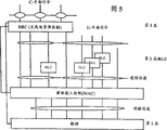
Fig. 5 is the schematic diagram with wave point structure general scheme of three protocol layers.
Fig. 6 is the schematic diagram of example of the e1 multiframe format E1 of common broadcast physical channel (BPCH) used according to the invention.
Fig. 7 A and Fig. 7 B illustrate many exchange point configurations that are used for duplexing carrier wave and the schematic diagram that is used for single exchange point configuration of duplexing carrier wave respectively.
Fig. 8 A and Fig. 8 B are the schematic diagrames that following two kinds of situations are described respectively: (A) be used to carry the use of the active downlink DPCH (DPCH) of common broadcast physical channel (BPCH); (B) generation of mute common broadcast physical channel (BPCH) when not having active downlink DPCH (DPCH).
Fig. 9 is the schematic diagram according to the subscriber station of the embodiment of the invention.
Figure 10 is the flow chart of explanation according to the general step that comprises in the subscriber station channel region offshoot program of the present invention.
Figure 11 is the flow chart of explanation according to the general step that comprises in the subscriber station channel selection scheme of the present invention.
Figure 12 is a schematic diagram how to avoid the example of blind spot when seamless the switching is described.
Embodiment
In the following description, for explain rather than limit for the purpose of, illustrate specific details, so that complete understanding of the present invention is provided such as ad hoc structure, interface, technology etc.But, to one skilled in the art, obviously can in other embodiment that breaks away from these specific detail, put into practice the present invention.In other example, save detailed description, so that do not allow unnecessary details make explanation of the present invention not obvious to well-known equipment, circuit and method.
Fig. 1 illustrates mobile communication system 20
1, it comprises a plurality of base station BSs
1,1To BS
1,5, they serve sub-district C separately respectively
1,1To C
1,5Each base station BS has one or more antennas, and one or more subscriber stations of sub-district C communicate with being positioned at separately by the air interface such as wireless channel for they.Accordingly, each base station BS has at least one radio frequency sending set and at least one radio-frequency transmitter.
Mobile communication system 20
1Base station BS
1,1To BS
1,5By land line or for example microwave link be connected to radio network controller (RNC) 22
1, this controller is called base station controller again.Radio network controller (RNC) 22
1Carry out various function well known by persons skilled in the art, comprise that (for example) is at mobile subscriber station needed handover operation when a sub-district moves to another sub-district.And Fig. 1 shows the mobile communication system 20 of example among Fig. 1
1Five sub-districts all by radio network controller (RNC) 22
1Control, mobile communication system of the present invention obviously can with cell operation more or less.And, one or more radio network controllers (RNC) can be included in the mobile communication system of the present invention, wherein the base station number of radio network controller (RNC) control has no particular limits, and all radio network controllers (RNC) also needn't be controlled the base station of similar number.
Radio network controller (RNC) 22
1Be connected to mobile switching centre (MSC) 24 by for example land line
1By mobile switching centre (MSC) 24
1, mobile communication system 20
1Be connected to other mobile communication system and fixing or line telecommunications system.Following U.S. Patent application provides base station, radio network controller (RNC), the structure of mobile switching centre (MSC) node and the example of operation of explanation mobile communication system, by reference all these United States Patent (USP)s is combined in this: the U.S. Patent application SN09/188102 that is entitled as " asynchronous transfer mode system "; The U.S. Patent application SN09/035821 that is entitled as " conversion of telecommunications exchange measurements "; The U.S. Patent application SN09/035788 that is entitled as " congested control between the telecommunications exchange "; And be entitled as the U.S. Patent application SN09/071866 of " paging between exchange ".
The situation that a plurality of mobile communication systems of special concern of the present invention are operated in inharmonic mode in having partly overlapping geographic area at least.In this, Fig. 2 illustrates mobile communication system 20
1Base station BS
1,1To BS
1,5Sub-district C separately
1,1To C
1,5(drawing), and mobile communication system 20 by solid line
2Base station and sub-district, mobile communication system 20
3Base station and sub-district.
Mobile communication system 20
2Comprise base station BS
2,1To BS
2,5Sub-district C separately
2,1To C
2,5(with dashed lines draws in Fig. 2); Mobile communication system 20
3Comprise base station BS
3,1To BS
3,5Sub-district C separately
3,1To C
3,5(in Fig. 2, drawing) with point-line.Thereby can determine from subscript: target first element is determined its mobile communication system under base station or the sub-district, and second subscript of base station or sub-district is determined special base station or sub-district in that system.
At least to a certain extent, each mobile communication system 20
1, 20
2With 20
3The overlay area of service has geographical overlapping.For example, subscriber station SS
1aAnd SS
1bBelong to mobile communication system 20
1, its position as shown in Figure 2.Subscriber station SS
1aBe arranged in the geographic area of all three mobile communication systems.In this, from Fig. 2 as seen, subscriber station SS
1aBe positioned at mobile communication system 20
1Sub-district C
1,1, mobile communication system 20
2Sub-district C
2,3In, mobile communication system 20
3Sub-district C
3,2In.Subscriber station SS
1bAt base station BS
1,3Scope restriction in, it is with maximum power work, if use identical carrier wave simultaneously, it will hinder BS
3,3The present invention is subscriber station SS
1aThe transmission that provides a kind of method to distinguish its three affiliated mobile communication system is used for determining to subscriber station SS
1aTransmission, and be used for Dynamic Selection and comprise subscriber station SS
1aRadio communication in the channel used.Below for the sake of simplicity, all references to subscriber station SS can be used as example subscriber station SS
1aUnderstand.
As mentioned above, the present invention also solve when the channel between the system cell again with 1 be impossible the time single system problem.For this situation, select suitable carrier wave/time slot channel (referring to following) automatically, so that the connection in the adjacent cell can not interfere with each other.Modern cdma system has the ability of compromise gain and instant user's bit rate.Thereby, in certain restriction, when increasing used bit rate, use again 1 no longer may, this can cause different districts heavy " craft " channel arrangement suddenly.The present invention can also avoid the needs of this arrangement.
Each mobile communication system shown in Fig. 2 has a plurality of radio-frequency carriers, and uses the code division multiple access (CDMA) with time division multiple access (TDMA) composition, as shown in Figure 3.For example, each mobile communication system uses four identical radio-frequency carrier F
1To F
4Each radio-frequency carrier F is divided into a plurality of time slots.In specific example shown in Figure 3, each radio-frequency carrier is divided into 16 time slots.Here, each combination of carrier wave and time slot is called carrier wave/time slot channel, is abbreviated as " C/TS " and " CH ".For example, for radio-frequency carrier F
1, mobile communication system 20
1Carrier wave/time slot channel CH is arranged
1,1,1To CH
1,1,16, and for radio-frequency carrier F
2, mobile communication system 20
1Has carrier wave/time slot channel CH
1,2,1To CH
1,2,16Similarly, for given radio-frequency carrier F
x, mobile communication system 20
2Has carrier wave/time slot channel CH
2, x, 1To CH
2, x, 16, and mobile communication system 20
3Has carrier wave/time slot channel CH
3, x, 1To CH
3, x, 16Therefore, can see that first element of target refers to the number of mobile communication system (for example mobile communication system 20 under carrier wave/time slot channel
1, 20
2Or 20
3); Second element refers to radio-frequency carrier (F for example
1, F
2, F
3Or F
4); Element refers to time slot (for example in the time slot 1 to 16).
The example of duplexing carrier wave/time slot channel is provided among Fig. 7 A and Fig. 7 B.With here the time, term " duplex " means a pair of uplink carrier/time slot channel and the downlink carrier/time slot channel in same frame and the same carrier wave.The time width of each frame among Fig. 7 A and the 7B all is 10 milliseconds.Each frame has 16 time slots (each time slot 625 microsecond).Fig. 7 A illustrates many exchange point configurations, and wherein downlink carrier/time slot channel back is followed by the uplink carrier/time slot channel of its pairing.As an example, the downlink carrier of shade/time slot channel CH
1,1,3The back followed by with downlink carrier/time slot channel CH
1,1,3Uplink carrier/time slot channel the CH of the shade of pairing
1,1,4On the other hand, Fig. 7 B illustrates the single exchange point configuration that is used for duplex, and wherein eight carrier waves/the time slot channel is used for down link in the front, and eight carrier waves in back/time slot channel is used for up link.For example in Fig. 7 B, the downlink carrier of shade/time slot channel CH
1,1,2Uplink carrier/time slot channel CH with shade
1,1,10Pairing.
Get back to Fig. 3, FDMA of the present invention inserts composition thereby ascribes the use of a plurality of radio frequencies to.TDMA inserts the time slot that composition ascribes each radio-frequency carrier to.CDMA access composition of the present invention ascribes each carrier wave/time slot channel to and holds the fact of a plurality of physical channel PCH.When being used for here, physical channel PCH is the combination of a sign indicating number, a time slot and a frequency.Physical channel (PCH) on each carrier wave/time slot channel (C/TS) is distinguished according to direct sequence (DS) CDMA spreading code.This is shown in Fig. 3 A, and Fig. 3 illustrates a representational carrier wave/time slot channel CH
1,1,6Has physical channel PCH
1,1,6,1To PCH
1,1,6, nThree elements in target front thereby corresponding to its 3rd element of following target of carrier wave/time slot channel under the physical channel PCH.The 4th element correspondence of target can be used for the specific DS-CDMA spreading code that telecommunications connects (for example calling out) under the physical channel PCH.Thereby, on each carrier wave/time slot channel, nearly n physical channel PCH being arranged, each is separated by the DS-CDMA sign indicating number.The transmission direction of all physical channels all is identical on the same carrier wave/time slot channel of same carrier wave.The same time of base station that has been equipped with a radio receiving-transmitting unit can only be operated a time slot of a carrier wave.For simplicity, the physical channel PCH of other carrier wave/time slot channel is not shown among Fig. 3, but will be appreciated that each carrier wave/time slot channel CH has and carrier wave shown in Fig. 3 A/time slot channel CH
1,1,6A plurality of physical channel PCH of same way as.
Subscriber station SS no matter be idle condition or communications status, can lock onto the base station of nearest (the strongest) in its system, uses as common DS-CDMA.In case automatically switch when another base station in the same system becomes stronger.Lock onto strong basis station and use with the link robustness all importantly for effective access channel again, this causes high capacity.Switching should be " seamless ", this means " carrying out before the interruption ", and this is important for high quality services.
Fig. 5 shows the general scheme of the wave point structure of three protocol layers: L1 (physical layer); L2 (data link layer); And L3 (network layer).Data link layer (L2) comprises Radio Link control (RLC) and medium access control (MAC).Network layer (L3) is divided into control plane (C-plane) and user plane (U-plane).TDD and FDD the 1st layer is very different, for the present invention of this reason makes the layers 2 and 3 of TDD and FDD identical as far as possible.Physical layer (PHL) is discerned according to transmission channel the service of medium access control (MAC).In the transmission channel some are common channels that a plurality of mobile subscriber stations use, and comprise Random Access Channel (RACH), forward access channel (FACH), broadcast channel (BCH) and paging channel (PaCH).Other of transmission channel are dedicated channel (DCH), for example are exclusively used in the specific channel that is connected of user data and control information between base station and the subscriber station.
The present invention uses four types physical channel-common broadcast physical channel (BPCH), DPCH (DPCH); Physical Random Access Channel (RAPCH); Insert physical channel (FAPCH) with forward direction.For each physical channel type, Fig. 4 shows: (1) is included in the one or more transmission channels in the physical channel, the type of the spread spectrum that uses on the direction of (2) physical channel (for example descending, up) and (3) physical channel.
As shown in Figure 4, DPCH (DPCH) comprises dedicated transmission channel (DCH), and can appear in the uplink and downlink link.DPCH (DPCH) goes up and allows fixing and variable spread spectrum.
When subscriber station will obtain wireless access, for example when carrying out connecting, use Physical Random Access Channel (RAPCH) such as the telecommunications of calling out.Physical Random Access Channel (RAPCH) thereby at uplink direction, and comprise the RACH transmission channel.In the embodiment that is exemplified, Physical Random Access Channel (RAPCH) has fixedly spreading code.As following described, in the present invention, Physical Random Access Channel (RAPCH) all is available on each potential up-link carrier/time slot channel.And subscriber station SS Dynamic Selection carrier wave/time slot channel is to be used for Physical Random Access Channel (RAPCH), and after the base station received, identical carrier wave/time slot channel was used as the DPCH (DPCH) that is used to connect.
Forward direction insert physical channel (FAPCH) be for example the base station to inserting request at random or the request of packet communication being responded and the channel of the down link direction used.Forward direction inserts physical channel (FAPCH) thereby comprises that forward direction inserts transmission channel (FACH).In the embodiment that is exemplified, forward direction inserts physical channel (FAPCH) fixedly spreading code.
As shown in Figure 4, common broadcast physical channel (BPCH) comprises broadcasting (BCH) and paging (PaCH) common transport channels.Thereby common broadcast physical channel (BPCH) has carried broadcast system identity and the capacity and the downlink synchronization information of giving subscriber station, also has the down link paging channel (PaCH) to subscriber station in addition.In the embodiment that is exemplified, common broadcast physical channel (BPCH) has fixedly spreading code.
Fig. 4 A illustrates how to make up physical channel, comprises that common broadcast physical channel (BPCH), Physical Random Access Channel (RAPCH), forward direction insert physical channel (FAPCH) and DPCH (DPCH).A time slot has comprised the midamble of 512 chips, and every end all has 1024 data chips.The protection clearance G S that before next time slot begins, also has 96 chips.Midamble is used to derive time slot and bit synchronous, need not carry out system identification.Certainly, also can use the preamble at time slot top to replace midamble.Midamble is identical for all systems, but is not to do like this.In another embodiment, each base station in system, can be specific on the midamble geography, or each C/TS is gone up CH simultaneously be specific.If realize being called the specific decoding technique of joint-detection, then back one type is useful.Thereby the specific spread spectrum code of the different physical channels of difference (PCH) only is used for a remaining 1024+1024=2048 chip among Fig. 4.They will carry the information content of physical channel.Use variable bandspread factor (SF) from 1 to 32, have 64 to 2048 bits to can be used for beared information on each physical channel.Suppose that frame rate is 100Hz (a 10ms frame length), original bit rate is 6.4kbps (SF=32) and 204.8kbps (SF=1).If 16 time slots are arranged, then whole chip-rate is 16 * (512+2048+96) * 100=4249600 chips/sec.This can realize that this depends primarily on the type of modulation on the wide frequency carrier of 5MHz.
In most preferred embodiment, RAPCH, FAPCH and DPCH adopt SF=16.This provides 12.8kbps (128 bits/time slot).This suitable DPCH speech business and RACH and FACH transmission fast.How forming RACH or FACH message is common knowledge, there is no need further explanation here.The example of the mapping of BCH on the BPCH and PaCH information is provided here.
In most preferred embodiment, extremely important because all free subscriber station SS receive BPCH information, so BPCH is used SF=32 or higher spreading factor.FS=32 will provide 6.4kbps or every time slot 64 bits.All BPCH information can not be filled in the time slot, but that is optional.Thereby, having defined the multiframe that comprises 16 frames among Fig. 6, each frame comprises 16 carrier waves/time slot channel (seeing Fig. 7 B) CH
X, x, 1And CH
X, x, 1616 carrier waves/time slot channel only is shown in Fig. 6 is used for first frame, should be appreciated that 16 all frames all have 16 carrier waves/time slot channel.Making the information of all dissimilar BPCH is possible in the different frame of two or more multiframes.In order to accomplish this point and the BPCH information that can receive correlation type, even imprecisely know which frame it comes from, 64 data bits in frame are divided into two parts, 4 bit descriptive information types, the remaining 60 bits information needed (shown in Fig. 4 B) that is used to encode.
For mobile system, the type of required information is a general knowledge among BCH and the PaCH, but table 1 provides the example of information needed type and how they are identified and are mapped in the different frame of multiframe.Different information types in the table 1 are mapped to multiframe with different priority.Paging information has the highest priority, and can send in all odd-numbered frame.The subscriber station that is in the current energy-saving mode of idle locking is as long as monitor frame 1.All paging frames have a bit to tell whether next odd-numbered frame comprises any paging content in the multiframe.Thereby frame 1 will notify in current multiframe paging information whether occurs in any odd-numbered frame subsequently.If the paging information that will not send in the odd-numbered frame, then subscriber station can return sleep state up to occurring paging frame again.
The example of the sign of information type and mapping on the different frame in table 1 multiframe
| Information type | Content in the message segment (60 bits that comprise detection bits) | In frame number, to send | |
| The type of information | Coding (4 bit) | ||
| PaCH. paging | 0000 | Global or temporary transient mobile subscriber identifier | 1,3,5,7,9,11,1 3,15 |
| BCH part 1 system identity | 0001 | System identity and transmitting base station identity | 2 |
| BCH part 2 is synchronous | 0010 | Timeslot number in the frame of the time slot that receives and the frame number in the multiframe (noticing that chip, bit and slot synchronization provide by midamble) | 4 |
| BCH part 3 power system capacities | 0011 | Coded message in the power system capacity | 6 |
| Be preserved for the information of other type | 0100-1111 | Any out of Memory type | 8,10,12,14,16 |
Number of C DMA system definition the certain synchronization channel, they may comprise or may not comprise some system identity information.Do not require among the present invention like this, because the midamble of common broadcast physical channel (BPCH) (other PCH with all) provides synchronous [the seeing Fig. 4 A] of chip, bit and time slot in common structure, remaining synchronously and system identity information provide (seeing Table 1) by BCH.
Common broadcast physical channel (BPCH) is dispensed on each active downlink carrier wave/time slot channel, and for example those have the carrier wave/time slot channel of effective DPCH (DPCH).Fig. 8 A illustrates mobile communication system 20
1Middle radio-frequency carrier F
1The single exchange point configuration of duplex channel, carrier wave/time slot channel CH wherein
1,1,1, CH
1,1,4, CH
1,1,5And CH
1,1,8Has effective traffic (shadow representation).Thereby, each carrier wave/time slot channel CH
1,1,1, CH
1,1,4, CH
1,1,5And CH
1,1,8Carrying common broadcast physical channel (BPCH).
If be less than two active downlink DPCH (DPCH), the base station produces one or two mute common broadcast physical channel (BPCH) on demand on different carrier/time slot channel.When the base station did not have other physical channel on the employed specific carriers of BPCH/time slot channel, BPCH was called mute BPCH.Under situation shown in Fig. 8 B, the active downlink DPCH of not sending from the base station (DPCH) this means that the base station must produce two mute common broadcast physical channels (BPCH) on different carrier/time slot channel, such as CH
1,1,4And CH
1,1,8Thereby such as CH
1,1,4And CH
1,1,8Two mute common broadcast physical channels (BPCH) each can carry common broadcast physical channel (BPCH).If have only an active downlink DPCH (DPCH) of sending from the base station, the base station must produce a mute common broadcast physical channel (BPCH).The subscriber station that has been equipped with a radio receiving-transmitting unit can only be operated the time slot (can operate on the different carrier at different time-gap under the multicarrier situation) on the carrier wave at one time.By always having effective BPCH at least two different time slots, subscriber station can communicate on a time slot, and still can detect peripheral cell in the same system, in case it is stronger than this sub-district that these sub-districts become, just carry out quick switching (because mobility of subscriber station) to these sub-districts.
Foundation and the mute common broadcast physical channel (BPCH) of maintenance on minimum carrier wave/time slot channel are being disturbed in the base station.In order to do like this, base station periodically (for example per second) is checked and the interference power of each carrier wave/time slot channel if desired, mute common broadcast physical channel (BPCH) is moved to new best carrier/time slot channel.When doing like this, when the free time locks mobile phone at sleep state, can produce short the pause certain image duration.Be activated because common broadcast physical channel (BPCH) has on professional descending carrier/time slot channel (for example DPCH) at each, when two carrier waves/time slot channel bearing was professional, mute common broadcast physical channel (BPCH) was released.When needs, mute common broadcast physical channel (BPCH) is activated again, so that at least two downlink carrier/time slot channels always have mute common broadcast physical channel (BPCH) on the same carrier wave.In order to avoid blind time slot when the seamless switching, different time slots can be selected in the base station, the time slot of being separated by at least between these time slots.Figure 12 provides from the sub-district 1 example how to avoid blind time slot to the sub-district during 2 seamless switchings.If do not have business in the sub-district 2, then the service bearer on the carrier wave 2 has been the second mute BPCH.
Thereby, according to the present invention, from carrier wave/time slot channel that send each base station, have at least two to have common broadcast physical channel (BPCH).All carrier waves/time slot channel with active downlink DPCH (DPCH) also carries common broadcast physical channel (BPCH) in mode shown in Fig. 8 A.
Fig. 9 illustrates the composition of example subscriber station SS.Subscriber station SS described here can be the mobile communication unit of any kind, comprises (for example) mobile phone or laptop computer.Subscriber station SS has its antenna 9-10, and they are connected to receiver and demodulator 9-12 and transmitter and modulator 9-14 suitably by switch 9-13.The whole operation control of subscriber station and the applied logic of subscriber station SS reside among processor and the control/applied logic 9-15.After this, for the sake of simplicity, processor and control/applied logic 9-15 are called processor 9-15 simply.
At the receiving unit of subscriber station, receiver and demodulator 9-12 demodulated information offer frame and time slot synchronization unit 9-16 and DS-sign indicating number and remove unit 9-18.Processor 9-15 receiver control and demodulator 9-12 and frame and time slot synchronization unit 9-16 are shown in the control line that processor 9-15 sends.Subscriber station uses one or more spreading codes to operate, and comprises fixedly spreading code of direct sequence predetermined or this machine (DS) spreading code and (among the embodiment that is exemplified), some physical channel that illustrates with reference to figure 4 above fixedly spreading code is used for.The spreading code that subscriber station SS uses is stored among the processor 9-15.Processor 9-15 removes unit 9-18 by line 9-20 to the DS-sign indicating number spreading code parameter is provided.The spreading code parameter of utilizing processor 9-15 to provide, DS-sign indicating number are removed unit 9-18 and determined: whether the input transmission has the spreading code identical with this machine of subscriber station, perhaps the input transmission whether have with subscriber station SS under mobile communication system 20
1The identical spreading code of fixedly spreading code that uses of public physical channel.If the DS-sign indicating number is removed unit 9-18 and detected this machine or fixing spreading code, it is decoded to the input transmission.The decoded data of acquisition offers multiplexing and divides with unit (multiplexing and branch 9-22) from the input transmission.By data/address bus 9-24, data multiplexing and divide with 9-22 and processor 9-15 between carry out two-way communication; By control bus 9-26, control information multiplexing and divide with 9-22 and processor 9-15 between carry out two-way communication.
The control and the applied logic that are included among the processor 9-15 of subscriber station SS can be various types of.The typical case who further specifies processor 9-15 execution below moves the example of the content of control and applied logic.And processor 9-15 communicates by interface bus 9-32 and user interface 9-30.For example, for typical mobile phone, user interface 9-30 can comprise telephone keypad.
At radiating portion, by multiplexing and divide with 9-22 and offer DS-sign indicating number adding device 9-40 from the data of processor 9-15 gating.DS-sign indicating number adding device 9-40 utilize this machine of receiving from processor 9-15 by circuit 9-42 or fixedly the DS code parameters data are encoded.Then, the data behind the coding are launched machine and modulator 9-14 modulation, and add correct frame by frame and time slot synchronization unit 9-16 to carrier wave/time slot channel.Then, by transmitter and modulator 9-14 to antenna 9-10 transmit frame information.For example in order to control purpose, transmitter and modulator 9-14 are connected to processor 9-15.Switch 9-13 controls by frame and time slot synchronization unit 9-16, and during transmission time slot antenna 9-10 is connected to transmitter 9-14, during receiving slot antenna 9-10 is connected to receiver 9-12.
The subscriber station SS that after physical channel and subscriber station SS have been described, can know (for example with reference to Figure 10 general step) position shown in Figure 2 now how with its mobile communication system 20
1Communicate (at mobile communication system 20
2With mobile communication system 20
3External transmission in).For example, if suppose subscriber station SS powers on shown in the step 10-1 among Figure 10.After starting, the receiver of subscriber station SS and demodulator 9-12 monitor its local frequency, i.e. Yu Ding one or more radio-frequency carrier F
1To F
4In, shown in figure step 10-1.Step 10-2 is illustrated in the information that receives on the local frequency and is removed unit 9-18 decoding by the DS-sign indicating number, and its attempt detects and is used for mobile communication system 20
1The spreading code of common broadcast physical channel (BPCH).In the embodiment that is exemplified, the spreading code that is used for common broadcast physical channel (BPCH) is fixing spreading code, this means that all (a plurality of at least) subscriber stations use the spreading code of common broadcast physical channels (BPCH) to be used to detect common broadcast physical channel (BpCH).When detecting, DS-sign indicating number removal unit 9-18 is used for its mobile communication system 20
1The spreading code of common broadcast physical channel (BPCH) time, multiplexing and divide with 9-22 and send BPCH information to processor 9-15, it checks the information content of common broadcast physical channel (BPCH) in step 10-3.Specifically, at step 10-3, check the system identifier (seeing Table the system identity in 1) that is included in the common broadcast physical channel (BPCH).Then, at step 10-4, whether the system identifier of carrying is identical with system identifier in the applied logic of the processor 9-15 that is pre-stored in subscriber station SS in the processor 9-15 check common broadcast physical channel (BPCH).In this, should be noted that other mobile communication system can use identical spreading code with going up at their common broadcast physical channel (BPCH), so the inspection of step 10-3 and step 10-4 is necessary.
In a further embodiment, the DS-sign indicating number is removed unit 9-18 from processor 9-15 Load System identifier, and step 10-3 and 10-4 remove among the unit 9-18 by hardware encoding at the DS-sign indicating number.If processor 9-15 is executive system identification promptly inadequately, then above-mentioned processing is useful.
In fact, if in decoded common broadcast physical channel (BPCH), determine the mobile communication system 20 that subscriber station SS is predetermined
1, then obtain number of frames, carrier wave/time slot channel number and synchronizing information (seeing Table 1) from common broadcast physical channel (BPCH), and they be stored among the processor 9-15 at step 10-5 subscriber station SS.Number of frames, the carrier wave/time slot channel number and the synchronizing information of collecting like this from common broadcast physical channel (BPCH) have been arranged, and subscriber station SS can lock onto its mobile communication system 20
1Framing, distinguish mobile communication system 20 thus
1The transmission and the transmission of other mobile communication system.
The above-mentioned explanation of the step among Figure 10 relates to and is used to detect common broadcast physical channel (BPCH) and to the monitoring of local frequency, locks onto the mobile communication system under the subscriber station SS thus.The present invention also provides the dynamic channel selection course of describing below in conjunction with basic step shown in Figure 11.
The processor 9-15 of the step 11-0 explanation subscriber station SS of Figure 11 receives the user's request that requires wireless access from user interface 9-30.User's request that this requirement inserts can take the user to dial the form of being callee's number, or starts the form that sends key on user interface 9-30.User request can also be the startup that sends key, as to the response from the bell signal of paged subscriber station.On this binding site, subscriber station is according to the said process and its mobile communication system 20 of Figure 10 explanation
1Carry out synchronously.Such being the case, at step 11-1, the processor 9-15 of subscriber station SS monitors each time slot of frame.If determine that at step 11-2 this frame has a mute common broadcast physical channel (BPCH) [seeing Fig. 8 B] of time slot carrying, then at step 11-3, whether the selected time slot of subscriber station SS determining step 11-2 has the predetermined minimum threshold T that needs above subscriber station SS
SSSignal to noise ratio (SIR).Signal to noise ratio (SIR) is measured in receiver and demodulator 9-12.If do not surpass minimum threshold T
SS, the program execution is returned step 11-2 and whether is carried mute common broadcast physical channel (BPCH) with definite another carrier wave/time slot channel, if, the inspection of repeating step 11-3.If determine minimum threshold T at step 11-3
SSCarrier wave/time slot channel by the mute common broadcast physical channel (BPCH) of carrying surpasses, and then at step 11-4, subscriber station SS sets up the wireless access request to the base station.The wireless access request is carried on the Physical Random Access Channel (RAPCH), and this channel is the duplexing centering of the carrier wave/time slot channel with the mute common broadcast physical channel (BPCH) of carrying.For example, if subscriber station SS selects the carrier wave/time slot channel CH of the mute common broadcast physical channel (BPCH) of carrying among Fig. 8 B
1,1,4, then at carrier wave/time slot channel CH
1,1,12Physical Random Access Channel on the access request of forwarding step 11-4.
After the access request of forwarding step 11-4, at step 11-5, the processor 9-15 of subscriber station SS checks whether the positive response to inserting request is received, and this FAPCH is on the right first available downlink carrier wave/time slot channel of duplex channel on forward direction access physical channel (FAPCH).In the above-mentioned explanation that relates to Fig. 8 B, the access request that wherein appears at step 11-4 occurs in carrier wave/time slot channel CH
1,1,12On, insert the carrier wave/time slot channel CH of physical channel (FAPCH) at step 11-5 expection forward direction at next frame
1,1,4On.If the positive response to the access request that comes from the base station is provided on suitable carrier wave/time slot channel, as step 11-5 was determined, then at step 11-6, subscriber station SS set up duplexing carrier wave/time slot channel application.
Duplex that step 11-6 sets up should in, carrying inserts the up-link carrier/time slot channel (carrier wave among Fig. 8 B/time slot channel CH for example of request
1,1,12) be used for uplink special physical channel (DPCH) connecting, and still the mute common broadcast physical channel (BPCH) of carrying and forward direction descending carrier/time slot channel of inserting physical channel (FAPCH) is used as downward special physical channel (DPCH) to be connected.In the embodiment that is exemplified, the message that (before promptly setting up duplexing carrier wave/time slot channel application) sends before the step 11-6 spreading code coding that is fixed, but after this use the spreading code of this machine of subscriber station SS, so that connect one that obtains in the physical channel shown in Figure 3.For example, in up link, connection can be used physical channel PCH
1,1,12,1(for example physical channel PCH uses carrier wave/time slot channel CH
1,1,12First spreading code), on down link, connection can be used physical channel PCH
1,1,4,1(for example physical channel PCH uses carrier wave/time slot channel CH
1,1,4First spreading code).
Contact step 11-5, after positive response is sent to the access request of step 11-4 in the base station, the descending carrier that is used for the request that is included in/time slot channel that the base station must at first be determined to measure in the base station (carrier wave/time slot channel CH for example
1,1,12) signal to noise ratio (SIR) whether surpassed minimum threshold T
BSIf surpassed minimum threshold T
BS, the base station can be inserted physical channel (FAPCH) at forward direction and go up the transmission positive response to subscriber station SS.If do not surpass lowest threshold, the base station does not respond the request of access.When subscriber station SS does not receive when response at step 11-5, subscriber station SS returns step 11-2 to search another mute common broadcast physical channel (BPCH).
If there is no mute common broadcast physical channel (BPCH), if the carrier wave of existing mute common broadcast physical channel (BPCH)/time slot channel is unavailable, then at step 11-10, subscriber station SS determines whether that from any effective DPCH (DPCH) of current base station of subscriber station SS being handled, wherein the SIR of correlated carrier wave/time slot channel surpasses the lowest threshold T of subscriber station SS
SSIf, there is such carrier wave/time slot channel, at step 11-11, the processor 9-15 of subscriber station SS selects the carrier wave/time slot channel of SIR maximum.Thereafter, subscriber station sends its access request (at step 11-12), and checks response (at step 11-13) before setting up new duplexing DPCH (step 11-14) with carrier wave/time slot channel of maximum SIR.Will be appreciated that step 11-12 discussed above, 11-13 are identical with step 11-4,11-5 and 11-6 respectively basically with 11-14, but comprised the carrier wave/time slot channel of the DPCH (DPCH) that maximum SIR is arranged, rather than the carrier wave/time slot channel of mute common broadcast physical channel (BPCH) has been arranged.
In step 11-13, if subscriber station SS does not receive from the base station inserting request responding, subscriber station SS turns back to step 11-10 to determine whether to have the minimum threshold T above subscriber station in its base station
SSAny other have the carrier wave/time slot channel of DPCH (DPCH).If there is such other carrier wave/time slot channel, with respect to the carrier wave/time slot channel of the DPCH with next maximum SIR (DPCH), execution in step 11-12, step 11-13 and step 11-14.
If base station for subscriber station, not as the determined carrier wave that DPCH (DPCH) is arranged/time slot channel that conforms with qualification of step 11-10, then at step 11-20, whether any carrier wave/time slot channel that definite the having from neighbor base station of subscriber station SS can be detected DPCH (DPCH) surpasses the minimum threshold T of subscriber station SS
SSIf deposit the one or more such DPCH (DPCH) that comes from neighbor base station, with respect to the carrier wave time slot channel of these DPCH (DPCH), execution in step 11-21 to 11-24.Step 11-21 to 11-24 is substantially the same in step 11-12, step 11-13 and step 11-14, and step 11-21 to 11-24 relates to the carrier wave with DPCH (DPCH)/time slot channel of coming from the base station of neighbor base station rather than subscriber station SS oneself (subscriber station synchronously and the base station that locks onto).
11-10 is determined as step, if do not conform with the carrier wave with DPCH (the DPCH)/time slot channel of qualification for the contiguous own system base-station of subscriber station SS, then at step 11-30, if more than one carrier wave is supported in the base station that subscriber station locks onto, subscriber station SS utilizes the carrier wave (F that selects at random
1To F
4) go up least interference carrier wave/time slot channel and set up new duplexing DPCH and connect.Understand new duplexing DPCH establishment of connection from above-mentioned correlation step 22-21 to 11-24.
The minimum threshold T of subscriber station SS
SSMinimum threshold T with the base station
BSDepend on Several Factors.These factors comprise the amount of processing gain, use the linking number of carrier wave/time slot channel and detecting and the performance of the concrete grammar of difference sign indicating number on same carrier wave/time slot channel.Can be different for different professional optimal thresholds, and can adjust optimal threshold from calling out to call out with type of call.
Thereby, for call setup or switching, subscriber station SS selects the duplexing carrier wave/time slot channel of least interference, and carries out direct DPCH foundation (20ms) by Physical Random Access Channel (RAPCH) and forward direction access physical channel (FAPCH) on the duplexing carrier wave/time slot channel that arrives strong basis station.This provides quick DPCH to insert.Subscriber station SS disperses and control is switched.This has been avoided cooperation complicated on the static infrastructure and thorny channel to select demand.The fact that DPCH selects to be undertaken by subscriber station SS basically can't prevent the supplementary that is similar to blind spot information or the control of bringing in from system.
Therefore the present invention provides instant dynamic channel option program for the direct sequence CDMA mobile radio system with TDMA composition and/or multicarrier (as FDMA)." immediately " means that making channel according to the demand of base station selects, and for example makes according to each calling or each connection.Preferably, promptly select by subscriber station SS by mobile phone.
Instant dynamic channel of the present invention is selected based on definition least interference channel (LIC).For duplexing Traffic Channel, least interference channel (LIC) is that duplexing carrier wave/time slot channel is right, wherein measures the down link as the right minimum wireless signal strength designator (RSSI) of all carrier waves/time slot channel at subscriber station SS place.For common broadcast physical channel (BPCH), or down link list industry affair channel, least interference channel (LIC) is duplexing carrier wave/right down link of time slot channel, and wherein the highest any one RSSI in right two time slots of carrier wave/time slot channel has all carrier waves/right minimum of time slot channel of measuring at the place, base station.Right time slot also is possible as belonging to duplexing carrier wave/time slot channel with definition least interference C/TS channel to replace duplex (or up single worker) Traffic Channel, and wherein the highest any one RSSI in right two time slots of carrier wave/time slot channel has all carrier waves/right minimum of time slot channel in the measurement of subscriber station place.
Effectively instant dynamic channel is selected based on a large amount of statistical rules.This means to have selection as much as possible to be used to select good channels so.Good channels so is the channel that has higher enough good signal to noise ratio (SIR) probability and have the existing low probability of interference that connects in identical systems or other any system.Effective application that instant dynamic channel is selected means that sometimes setting up new calling will disturb existing calling, will be forced to move to (for example switching) another carrier wave/time slot channel then.If not only Traffic Channel but also broadcasting, synchronously, paging and access channel all dynamically selected, this is with regard to no problem (this occurs in the present invention).
Therefore, in the present invention, do not have particular carrier wave or carrier wave/time slot channel to be used for BPCH, RAPCH or FAPCH, in the case, those may be to disturb, so whole base station may can not be operated.The plan, and expensive and do not conform to actual time synchronized between all systems is forced in the fixed position of these channels.
The present invention preferably makes instant dynamic channel option program be independent of the processing gain amount that the DS-CDMA cataloged procedure uses.Bigger processing gain means in identical time slot and has more calling.The present invention is therefore relevant with the processing gain different and that change that is connected realization with different channels.For make this feature be reduced to low-down processing gain (as in addition drop to 1), may need partial common broadcast physical channel (BPCH) to go up by time-multiplexed in DPCH (DPCH).Can in each time slot, carry out this time-multiplexedly, perhaps suitable, in several time slots, carry out.Processing gain is being hanged down on some or all of carrier waves/time slot channel so that under the situation of an only superfluous physical channel perhaps, whole common broadcast physical channel (BPCH) must be gone up by time-multiplexed in the DPCH (DPCH) of these carrier waves/time slot channel.This allows common broadcast physical channel (BPCH) available on each effective carrier wave/time slot channel.In this case, simplify the program of Figure 11 by the inspection of bypass 11-10 and 11-20.In this, forward direction access physical channel (FAPCH) also must be similarly by time-multiplexed.
The present invention preferably also allows the coexistence of inharmonic device of DS-CDMA mobile radio system on the public spectrum allocation may.The present invention is mainly used in but is not limited to be applied to many dwellings and offices system in the same geographical area.For example, mobile communication system 20 shown in Figure 2
1To 20
3Can all be positioned at Office Area or Technology Park on these companies or the mechanism's geography by different companies or mechanism's operation.The present invention also is applied to distribute to a public operator's frequency spectrum exclusively or is used for public (for example unwarranted) distribution of a plurality of operators.
The present invention is therefore by allowing the connection of different system utilize different carrier waves/time slot channel to allow effectively to adopt different geographical overlapping DS-CDMA systems.Different carrier waves/time slot channel provides necessary isolation between the wireless connections of different system, instant dynamic channel option program of the present invention is used to select suitable carrier wave/time slot channel.
Another advantage of the present invention is to coexist with multicarrier (MC) tdma system of the suitable species that uses instant dynamic channel to select.
In a specific example implementation, in frequency range 1900 to 1920MHz, provide four radio-frequency carrier F
1To F
4The invention is not restricted to use four radio-frequency carriers, also be not limited to each radio-frequency carrier 16 time slots are provided.Will know, and can use radio-frequency carrier more or less, and each radio-frequency carrier can provide time slot more or less.In fact, even mobile communication system only uses a radio-frequency carrier also can put into practice the present invention.
Here the embodiment that is exemplified inserts physical channel (FAPCH) for common broadcast physical channel (BPCH), Physical Random Access Channel (RAPCH) and forward direction fixedly spreading code.Fixedly spreading code is the predetermined DS-CDMA sign indicating number that can be directly used in these physical channel decodings and coding, and some advantage is provided thus.But, should be understood that to present invention includes the embodiment that on these physical channels, also allows the variable spread spectrum sign indicating number.
And Fig. 9 has represented the composition of subscriber station SS, in order to understand the present invention, should be understood that similar composition can be in the embodiment of base station.In such base station embodiment, processor control base station and execution are suitable for the applied logic of base station, and are connected to the base station user interface.
Described embodiment has illustrated the CDMA mobile communication system with TDMA composition at this.But, it will also be appreciated that the TDMA composition is optional, principle of the present invention also can be used for having only the CDMA of FDMA composition.Just, though instant dynamic channel selection described here is generally used for frequency domain and time domain, yet if having only a territory to use in these territories, the present invention is suitable equally.
As mentioned above, instant dynamic channel selection is a favorable characteristics of the present invention.For identical specific blocking probability, on an average, instant dynamic channel selection of the present invention makes than fixed channel assignment (FCA) and realize channel usefulness again on shorter geographic distance, thus, compare fixed channel assignment (FCA), local available interference restricted service capacity increases.But, should be understood that aspect of the present invention can replace fixed channel assignment (FCA) and realize.Therefore, the present invention can not be construed to than the feature that requires instant dynamic channel to select needs instant dynamic channel to select.
Although various duplexing schemes have been described, according to the present invention, each time slot on the carrier wave, for example each carrier wave/time slot channel can be distributed to down link or up link.Such flexibility has been arranged, and tdd mode can be adapted to different environment and different developments.In any configuration, at least one time slot must be allocated for down link on the carrier wave, and at least one time slot must be allocated for up link on this carrier wave.
Although with illustrated embodiments the present invention is described in conjunction with being considered to most realistic at present, yet know, the present invention is not limited to the disclosed embodiments, and on the contrary, the present invention covers various modifications and the equivalents in the spirit and scope that are included in the appended claim book.
Claims (66)
1. telecommunication system, it comprises the base station that at least one communicates by air interface and subscriber station, wherein: the wireless radio transmission in the described telecommunication system inserts uses the code division multiple access (CDMA) with time division multiple access (TDMA) composition; At least make up from described base station broadcast common broadcast physical channel by a plurality of effective traffic carrier waves/time slot; The CDMA coding is used for described common broadcast physical channel; And described common broadcast physical channel comprises (1) broadcast system identity information and (2) paging information.
2. the system of claim 1 is characterized in that: for described base station, two effective common broadcast physical channels on different time-gap are always arranged at least.
3. the system of claim 1, it is characterized in that: described two or more common broadcast physical channels are placed in described base station on the effective traffic time slot, if but were less than two effective traffic time slots, then described base station would produce mute common broadcast physical channel on the non-business time-slot of least interference.
4. the system of claim 3 is characterized in that: described base station monitors guaranteeing that described mute common broadcast physical channel remains on the least interference time slot, and whether described mute common broadcast physical channel is not reoriented to described least interference time slot.
5. the system of claim 2 is characterized in that: described base station produces mute common broadcast physical channel on the least interference time slot.
6. the system of claim 1, it is characterized in that: fixedly direct sequence CDMA sign indicating number is used for described common broadcast physical channel.
7. the system of claim 1 is characterized in that: described subscriber station selects to be used for sending to described base station the carrier wave/time slot of the request of access.
8. the system of claim 7 is characterized in that: described carrier wave/time slot that described subscriber station selects to be used for to send to described base station the request of access also is used for Traffic Channel.
9. the system of claim 7 is characterized in that: described subscriber station selects least interference carrier wave/time slot as the described carrier wave/time slot that is used for sending to described base station the request of access.
10. the system of claim 7, it is characterized in that: one receives described access request, for accepting to insert request, described base station just sends by the next downlink carrier/time slot that is included in duplexing centering and replys, and described duplex selects to be used for sending to described base station the described carrier wave/time slot of described access request to comprising described subscriber station.
11. the system of claim 7, it is characterized in that: described subscriber station selects least interference uplink carrier/time slot as the described carrier wave/time slot that sends the request of access to described base station, carrier wave/the time slot of described selection must surpass first predetermined threshold, and the duplex of locating uplink carrier/time slot that measure, described selection in described base station must surpass second threshold value to downlink carrier/time slot.
12. the system of claim 11 is characterized in that: selecting described least interference carrier wave/time slot as the described carrier wave/time slot that is used for sending to described base station the request of access, described subscriber station uses following order of priority:
(1) has the duplexing carrier wave/time slot channel of mute common broadcast channel;
(2) has the most duplexing carrier wave/time slot channel of the effective traffic channel of the described base station of close described subscriber station;
(3) has the duplexing carrier wave/time slot channel of the effective traffic channel of neighbor base station;
Least interference on carrier wave duplex carrier wave/time slot channel at random.
13. the system of claim 1 is characterized in that: at given time, in the connection between described base station of carrying and the described subscriber station on the physical channel of described system, described physical channel is by coding, time slot and frequency definition.
14. the system of claim 1, it is characterized in that: described broadcast system identity comprises and is used for making described subscriber station can distinguish the information of telecommunication system and other any telecommunication system that moves under the described user in same geographic area, and described subscriber station is used for described broadcast system identity the framing transmission from the telecommunication system under the described user thus.
15. the system of claim 9 is characterized in that: described broadcast system identity also comprises the sign of the base station of the telecommunication system under the described user.
16. one kind is carried out method of operation to the telecommunication system that comprises the base station that at least one communicates by air interface and subscriber station, said method comprising the steps of:
Use has the code division multiple access (CDMA) of time division multiple access (TDMA) composition, and the wireless radio transmission that is used for described telecommunication system inserts;
At least make up from described base station broadcast common broadcast physical channel by a plurality of effective traffic carrier waves/time slot, the CDMA coding is used for described common broadcast physical channel; And
In described common broadcast physical channel, comprise (1) broadcast system identity information and (2) paging information.
17. the method for claim 16 is characterized in that also comprising:, keep at least two effective common broadcast physical channels on different time-gap for described base station.
18. the method for claim 17, it is characterized in that also comprising: described base station is placed on described two common broadcast physical channels on the effective traffic time slot, if yet being less than two effective traffic time slots, described base station produces mute common broadcast physical channel on the non-business time-slot of least interference.
19. the method for claim 18, it is characterized in that also comprising: described base station monitors guaranteeing that described mute common broadcast physical channel still remains on the least interference time slot, and whether not the reorientation of described mute common broadcast physical channel at the least interference time slot.
20. the method for claim 16 is characterized in that also comprising: described base station produces mute common broadcast physical channel on the least interference time slot.
21. the method for claim 16 is characterized in that also comprising: described common broadcast physical channel is used fixing direct sequence CDMA sign indicating number.
22. the method for claim 16 is characterized in that also comprising: described subscriber station selects to be used for sending to the base station carrier wave/time slot of the request of access.
23. the method for claim 22 is characterized in that also comprising:, also use the described carrier wave/time slot of selecting by described subscriber station that is used for sending the request of access to described base station for Traffic Channel.
24. the method for claim 22 is characterized in that also comprising: described subscriber station selects least interference carrier wave/time slot as the described carrier wave/time slot that sends the request of access to described base station.
25. the method for claim 22, it is characterized in that also comprising: one receives that described acceptance inserts request, just send response by the next downlink carrier/time slot that is included in duplexing centering from described base station, described duplex selects to be used for sending to described base station the described carrier wave/time slot of described access request to comprising described subscriber station.
26. the method for claim 24, it is characterized in that: described subscriber station selects carrier wave/time slot that least interference uplink carrier/time slot comprises the described selection of requirement as the described carrier wave/time slot that sends from the request of access to described base station greater than first predetermined threshold, must be higher than second predetermined threshold in the duplex of place, described base station uplink carrier/time slot that measure, described selection to downlink carrier/time slot.
27. the method for claim 26 is characterized in that: in step from the request of access to described base station that select described least interference uplink carrier/time slot as the described carrier wave/time slot that sends, described subscriber station uses following priority:
(1) has the duplexing carrier wave/time slot channel of mute common broadcast channel;
(2) has the most duplexing carrier wave/time slot channel of the effective traffic channel of the described base station of close described subscriber station;
(3) has the duplexing carrier wave/time slot channel of the effective traffic channel of neighbor base station;
Least interference on carrier wave duplex carrier wave/time slot channel at random.
28. the method for claim 16 is characterized in that: at given time, in the connection between described base station of carrying and the described subscriber station on the physical channel of described system, described physical channel is by coding, time slot and frequency definition.
29. the method for claim 16 is characterized in that also comprising: described subscriber station uses described broadcast system identity information to distinguish other any telecommunication system of operation in affiliated telecommunication system of described user and the same geographic area.
30. the method for claim 29 is characterized in that also comprising: described subscriber station uses described broadcast system identity information, is used for the framing transmission of the affiliated telecommunication system of described user.
31. one kind to second telecommunication system manage at least in part overlapping covering first telecommunication system carry out method of operating, described first telecommunication system has at least one first system base-station that communicates by the air interface and the first system user station, and the wireless radio transmission in wherein said first telecommunication system inserts uses the code division multiple access (CDMA) with time division multiple access (TDMA) composition; Said method comprising the steps of:
Use the CDMA sign indicating number to come to broadcast the common broadcast physical channel by a plurality of effective traffic carrier waves/time slot combination from described first system base-station at least, described common broadcast physical channel comprises the broadcast system identity information; And
In the described first system user station, use described broadcast system identity information to distinguish the transmission of described first telecommunication system and described second telecommunication system.
32. the method for claim 31 is characterized in that also comprising: in the described first system user station, use described broadcast system identity information, be used for the framing transmission of described first telecommunication system.
33. the method for claim 31 is characterized in that also comprising: in described common broadcast physical channel, also comprise paging information.
34. the method for claim 31 is characterized in that also comprising:, keep at least two effective common broadcast physical channels on different time-gap for described first system base-station.
35. the method for claim 34, it is characterized in that also comprising: described first system base-station is placed on described two common broadcast physical channels on the effective traffic time slot, if but were less than two effective traffic time slots, then described base station would produce mute common broadcast physical channel on the non-business time-slot of least interference.
36. the method for claim 35, it is characterized in that also comprising: described first system base-station monitors guaranteeing that described mute common broadcast physical channel remains on the least interference time slot, and whether not the reorientation of described mute common broadcast physical channel on described least interference time slot.
37. the method for claim 33 is characterized in that also comprising: described first system base-station produces mute common broadcast physical channel on the least interference time slot.
38. the method for claim 31 is characterized in that also comprising: described common broadcast physical channel is used fixedly direct sequence CDMA sign indicating number.
39. the method for claim 31 is characterized in that also comprising: the carrier wave/time slot of the request of access is selected to be used for sending to described first system base-station in the described first system user station.
40. the method for claim 31 is characterized in that also comprising: for Traffic Channel, the described carrier wave/time slot that is used for sending the request of access that also uses the described first system user station to select to described first system base-station.
41. the method for claim 31 is characterized in that also comprising: the described first system user station selects least interference carrier wave/time slot as the described carrier wave/time slot that is used for sending to described first system base-station request of access.
42. the method for claim 40, it is characterized in that also comprising: one receives described acceptance inserts request, just send response being included on the next downlink carrier/time slot of duplexing centering from described first system base-station, described duplex selects to be used for sending to described first system base-station described carrier wave/time slot of described access request to comprising the described first system user station.
43. the method for claim 31, it is characterized in that: at given time, in the connection between described first system base-station of carrying and the described first system user station on the physical channel of described first telecommunication system, described physical channel is by coding, time slot and frequency definition.
44. manage first telecommunication system of overlapping covering at least in part with second telecommunication system for one kind, the wireless radio transmission in wherein said first telecommunication system inserts uses the code division multiple access (CDMA) with time division multiple access (TDMA) composition; Described first telecommunication system comprises:
Described first telecommunication system has at least one first system base-station that communicates by the air interface and the first system user station, described first system base-station utilizes CDMA sign indicating number broadcasting common broadcast physical channel by a plurality of at least effective traffic carrier waves/time slot combination, and described common broadcast physical channel comprises the broadcast system identity information; With
The first system user station, it uses described broadcasting identity information to distinguish the transmission of described telecommunication system and described second telecommunication system.
45. the equipment of claim 44 is characterized in that: the framing transmission in described first telecommunication system of described broadcast system identity information is used at the described first system user station.
46. the equipment of claim 44 is characterized in that: described first system base-station also comprises paging information in described common broadcast physical channel.
47. the equipment of claim 44 is characterized in that: at least two effective common broadcast physical channels on different time-gap of described first system base-station broadcasting.
48. the equipment of claim 47, it is characterized in that: described first system base-station is placed on described two or more common broadcast physical channels on the effective traffic time slot, if but were less than two effective traffic time slots, then described base station would produce mute common broadcast physical channel on the non-business time-slot of least interference.
49. the equipment of claim 48, it is characterized in that: described first system base-station monitors guaranteeing that described mute common broadcast physical channel remains on the least interference time slot, and whether not the reorientation of described mute common broadcast physical channel on described least interference time slot.
50. the equipment of claim 44 is characterized in that: described first system base-station produces mute common broadcast physical channel on the least interference time slot.
51. the equipment of claim 44 is characterized in that: described common broadcast physical channel is used fixedly direct sequence CDMA sign indicating number.
52. the equipment of claim 44 is characterized in that: the carrier wave/time slot of the request of access is selected to be used for sending to described first system base-station in the described first system user station.
53. the equipment of claim 52 is characterized in that: described carrier wave/time slot that the described first system user station is selected is used for sending to described first system base-station request of access also is used for Traffic Channel.
54. the equipment of claim 52 is characterized in that: the described first system user station selects least interference carrier wave/time slot as the described carrier wave/time slot that is used for sending to described first system base-station request of access.
55. the equipment of claim 52, it is characterized in that: one receives that described acceptance inserts request, described first system base-station just sends response by the next downlink carrier/time slot that is included in duplexing centering, and described duplex selects to be used for sending to described first system base-station carrier wave/time slot of described access request to comprising the described first system user station.
56. the equipment of claim 52, it is characterized in that: at given time, in the connection between described first system base-station of carrying and the described first system user station on the physical channel of described first telecommunication system, described physical channel is by coding, time slot and frequency definition.
57. a telecommunication system, it comprises the base station that at least one communicates by air interface and subscriber station, and wherein: the wireless radio transmission in the described telecommunication system inserts uses the code division multiple access (CDMA) that time division multiple access (TDMA) composition is arranged;
Duplex channel comprise have a stipulated time relation be combined into right uplink carrier/time slot combination with downlink carrier/time slot, the described carrier wave that is used for described access request response of the carrier wave that is used to the request that inserts of described subscriber station/time slot combination and described base station/time slot combination, with the up link subsequently and the downlink dedicated physical channels that are used for being connected between described subscriber station and the described base station, use identical duplex channel;
The CDMA sign indicating number is used for described DPCH.
58. the system of claim 57 is characterized in that: described access request and described access request response are encoded with fixing spreading code.
59. the system of claim 57 is characterized in that: the spreading code with described this machine of subscriber station is encoded to described DPCH.
60. the system of claim 57, it is characterized in that: described base station be used to insert the request response described carrier wave/the common broadcast physical channel is also carried in time slot combination, and described common broadcast physical channel comprises (1) broadcast system identity information and (2) paging information.
61. the system of claim 60 is characterized in that: the CDMA sign indicating number is used for described common broadcast physical channel.
62. one kind is carried out method of operation to first telecommunication system that comprises the base station that at least one communicates by air interface and subscriber station, said method comprising the steps of:
Described subscriber station sends the request of access to described base station;
Described base station sends to described subscriber station and inserts the request response;
Use has the code division multiple access (CDMA) of time division multiple access (TDMA) composition, is used for the wireless radio transmission of described telecommunication system;
The carrier wave that is used for described access request response of the carrier wave that is used for described access request of wherein said subscriber station/time slot combination and described base station/time slot combination also is used as up link and downlink dedicated physical channels respectively, is used for the connection between described subscriber station and the described base station;
And the CDMA sign indicating number is used for described DPCH.
63. the method for claim 62 is characterized in that also comprising with fixing spreading code described access request and described access request response is encoded.
64. the method for claim 62 is characterized in that also comprising: the spreading code with described this machine of subscriber station is encoded to described DPCH.
65. the method for claim 54, it is characterized in that also comprising: the described carrier wave/time slot that is used to insert the request response in described base station makes up carrying common broadcast physical channel, and described common broadcast physical channel comprises (1) broadcast system identity information and (2) paging information.
66. the method for claim 65 is characterized in that the CDMA sign indicating number is used for described common broadcast physical channel.
Applications Claiming Priority (3)
| Application Number | Priority Date | Filing Date | Title |
|---|---|---|---|
| US09/252990 | 1999-02-19 | ||
| US09/252,990 US6483826B1 (en) | 1999-02-19 | 1999-02-19 | Utilization of plural multiple access types for mobile telecommunications |
| US09/252,990 | 1999-02-19 |
Publications (2)
| Publication Number | Publication Date |
|---|---|
| CN1347627A CN1347627A (en) | 2002-05-01 |
| CN1227940C true CN1227940C (en) | 2005-11-16 |
Family
ID=22958389
Family Applications (1)
| Application Number | Title | Priority Date | Filing Date |
|---|---|---|---|
| CNB008063052A Expired - Fee Related CN1227940C (en) | 1999-02-19 | 2000-02-15 | Utilization of plural multiple access types for mobile telecommunications |
Country Status (10)
| Country | Link |
|---|---|
| US (1) | US6483826B1 (en) |
| EP (1) | EP1153521A1 (en) |
| JP (1) | JP4523171B2 (en) |
| CN (1) | CN1227940C (en) |
| AR (1) | AR022635A1 (en) |
| AU (1) | AU3203000A (en) |
| CA (1) | CA2364320C (en) |
| MY (1) | MY124200A (en) |
| TW (1) | TW492262B (en) |
| WO (1) | WO2000049828A1 (en) |
Families Citing this family (52)
| Publication number | Priority date | Publication date | Assignee | Title |
|---|---|---|---|---|
| DE59903475D1 (en) * | 1998-06-23 | 2003-01-02 | Siemens Ag | METHOD FOR CONTROLLING THE PERFORMANCE OF POINT TO MULTI-POINT CONNECTIONS IN WIRELESS TELECOMMUNICATION SYSTEMS IN UNCOORDINATED UNLICENSED SYSTEM OPERATION |
| KR100304648B1 (en) * | 1998-12-31 | 2001-09-29 | 윤종용 | Method for allocating resoures wireless in wireless communication system |
| US6775260B1 (en) * | 1999-02-25 | 2004-08-10 | Texas Instruments Incorporated | Space time transmit diversity for TDD/WCDMA systems |
| GB9906198D0 (en) * | 1999-03-18 | 1999-05-12 | Lucent Technologies Inc | Improved random access channel |
| DE60044928D1 (en) * | 1999-04-29 | 2010-10-21 | Samsung Electronics Co Ltd | DEVICE AND METHOD FOR SYNCRONIZING CHANNELS IN A BROADBAND W-CDMA COMMUNICATION SYSTEM |
| US6674787B1 (en) * | 1999-05-19 | 2004-01-06 | Interdigital Technology Corporation | Raising random access channel packet payload |
| US6917597B1 (en) * | 1999-07-30 | 2005-07-12 | Texas Instruments Incorporated | System and method of communication using transmit antenna diversity based upon uplink measurement for the TDD mode of WCDMA |
| US7023833B1 (en) | 1999-09-10 | 2006-04-04 | Pulse-Link, Inc. | Baseband wireless network for isochronous communication |
| US6526034B1 (en) * | 1999-09-21 | 2003-02-25 | Tantivy Communications, Inc. | Dual mode subscriber unit for short range, high rate and long range, lower rate data communications |
| FI109568B (en) * | 2000-01-13 | 2002-08-30 | Nokia Corp | Optimized sleep mode |
| US6778835B2 (en) * | 2000-03-18 | 2004-08-17 | Lg Electronics Inc. | Method for allocating physical channel of mobile communication system and communication method using the same |
| DE10054193A1 (en) * | 2000-11-02 | 2002-05-08 | Siemens Ag | Improvements to or relating to mobile telecommunications systems |
| SE0004326D0 (en) * | 2000-11-24 | 2000-11-24 | Ericsson Telefon Ab L M | Base station identification |
| US6996082B2 (en) | 2001-05-14 | 2006-02-07 | Interdigital Technology Corporation | Method and apparatus for minimizing the amount of data necessary to signal code and timeslot assignments |
| US7912014B2 (en) * | 2001-09-28 | 2011-03-22 | At&T Intellectual Property Ii, Lp | Method and apparatus for reducing interference in multiple-input-multiple-output (MIMO) systems |
| US20030166404A1 (en) * | 2001-11-15 | 2003-09-04 | Chuang Justin Che-I | Progressive reuse partitioning for improved interference rejection in wireless packet networks |
| WO2003047174A1 (en) * | 2001-11-27 | 2003-06-05 | Sharp Kabushiki Kaisha | Radio communication system |
| JP4002242B2 (en) * | 2002-03-25 | 2007-10-31 | インターデイジタル テクノロジー コーポレーション | Blind code detection method and apparatus |
| US7177658B2 (en) | 2002-05-06 | 2007-02-13 | Qualcomm, Incorporated | Multi-media broadcast and multicast service (MBMS) in a wireless communications system |
| US6631269B1 (en) * | 2002-05-23 | 2003-10-07 | Interdigital Technology Corporation | Signaling connection admission control in a wireless network |
| US7433347B1 (en) * | 2002-06-28 | 2008-10-07 | Arraycomm, Llc | Broadcast superframe with variable reuse and interference levels for a radio communications system |
| CN101035374A (en) | 2002-08-01 | 2007-09-12 | 美商内数位科技公司 | Method for coodinating paging occasions on a common paging channel |
| US7016327B2 (en) | 2002-08-21 | 2006-03-21 | Qualcomm Incorporated | Method and system for communicating content on a broadcast services communication system |
| JP3971984B2 (en) * | 2002-10-15 | 2007-09-05 | 松下電器産業株式会社 | Communication apparatus and communication method |
| US7586874B2 (en) * | 2003-01-06 | 2009-09-08 | Interdigital Technology Corporation | Wireless communication method and apparatus for providing multimedia broadcast services |
| KR101022066B1 (en) * | 2003-05-17 | 2011-03-17 | 엘지전자 주식회사 | Structure uplink control challel structure and time-code allocationg method the same |
| US7318187B2 (en) | 2003-08-21 | 2008-01-08 | Qualcomm Incorporated | Outer coding methods for broadcast/multicast content and related apparatus |
| US8694869B2 (en) | 2003-08-21 | 2014-04-08 | QUALCIMM Incorporated | Methods for forward error correction coding above a radio link control layer and related apparatus |
| US8804761B2 (en) | 2003-08-21 | 2014-08-12 | Qualcomm Incorporated | Methods for seamless delivery of broadcast and multicast content across cell borders and/or between different transmission schemes and related apparatus |
| US7181220B2 (en) * | 2003-09-24 | 2007-02-20 | Intel Corporation | Seamless roaming apparatus, systems, and methods |
| US7848305B2 (en) * | 2005-02-03 | 2010-12-07 | Qualcomm Incorporated | Techniques for accessing a wireless communication system with tune-away capability |
| US7742444B2 (en) | 2005-03-15 | 2010-06-22 | Qualcomm Incorporated | Multiple other sector information combining for power control in a wireless communication system |
| US8750908B2 (en) | 2005-06-16 | 2014-06-10 | Qualcomm Incorporated | Quick paging channel with reduced probability of missed page |
| US9055552B2 (en) | 2005-06-16 | 2015-06-09 | Qualcomm Incorporated | Quick paging channel with reduced probability of missed page |
| US20090207790A1 (en) | 2005-10-27 | 2009-08-20 | Qualcomm Incorporated | Method and apparatus for settingtuneawaystatus in an open state in wireless communication system |
| WO2007050911A1 (en) | 2005-10-27 | 2007-05-03 | Qualcomm Incorporated | A method and apparatus for transmitting and receiving access grant block over f-ssch in wireless communication system |
| US8266535B2 (en) | 2006-09-11 | 2012-09-11 | Broadnet Teleservices, Llc | Teleforum apparatus and method |
| US9215669B2 (en) * | 2007-11-16 | 2015-12-15 | Qualcomm Incorporated | Preamble design for a wireless signal |
| US8918112B2 (en) * | 2007-11-16 | 2014-12-23 | Qualcomm Incorporated | Preamble design for a wireless signal |
| US9264976B2 (en) | 2007-11-16 | 2016-02-16 | Qualcomm Incorporated | Preamble design for a wireless signal |
| US20090129333A1 (en) * | 2007-11-16 | 2009-05-21 | Qualcomm Incorporated | Preamble design for a wireless signal |
| US9801188B2 (en) * | 2008-02-01 | 2017-10-24 | Qualcomm Incorporated | Backhaul signaling for interference avoidance |
| US8768372B2 (en) * | 2008-02-13 | 2014-07-01 | Qualcomm Incorporated | Sector interference management based on inter-sector performance |
| JP4531825B2 (en) * | 2008-03-28 | 2010-08-25 | 京セラ株式会社 | Wireless terminal device |
| PL2289271T3 (en) * | 2008-06-06 | 2014-01-31 | Hmd Global Oy | Cell-selective network access |
| EP2180748B1 (en) * | 2008-10-21 | 2017-04-05 | Fujitsu Limited | Inter-cell interference mitigation signalling methods |
| JP5245761B2 (en) * | 2008-11-26 | 2013-07-24 | 富士通株式会社 | Transmission device, reception device, transmission method, and reception method |
| CN101998680B (en) * | 2009-08-24 | 2016-01-13 | 中兴通讯股份有限公司 | The sending method of number of frames and Node B and service wireless network controller |
| JP4728434B1 (en) * | 2010-02-15 | 2011-07-20 | 株式会社エヌ・ティ・ティ・ドコモ | Mobile station and radio base station |
| US8495199B2 (en) * | 2011-12-22 | 2013-07-23 | Amazon Technologies, Inc. | Interfaces to manage service marketplaces accessible via direct network peerings |
| US9226292B2 (en) * | 2013-07-17 | 2015-12-29 | Cisco Technology, Inc. | Resilient forwarding of packets in an ARC chain topology network |
| CN109818704B (en) | 2017-11-21 | 2020-05-19 | 华为技术有限公司 | Data transmission method and device |
Family Cites Families (10)
| Publication number | Priority date | Publication date | Assignee | Title |
|---|---|---|---|---|
| US5603081A (en) | 1993-11-01 | 1997-02-11 | Telefonaktiebolaget Lm Ericsson | Method for communicating in a wireless communication system |
| FI925472A (en) * | 1992-12-01 | 1994-06-02 | Nokia Mobile Phones Ltd | Data transfer procedure and system |
| JP2636712B2 (en) * | 1993-12-08 | 1997-07-30 | 日本電気株式会社 | Mobile communication device |
| US5481533A (en) * | 1994-05-12 | 1996-01-02 | Bell Communications Research, Inc. | Hybrid intra-cell TDMA/inter-cell CDMA for wireless networks |
| JP3566435B2 (en) * | 1995-12-19 | 2004-09-15 | キヤノン株式会社 | Wireless switching system |
| US5894473A (en) * | 1996-02-29 | 1999-04-13 | Ericsson Inc. | Multiple access communications system and method using code and time division |
| US6085085A (en) | 1996-03-27 | 2000-07-04 | Qualcomm Incorporated | Method and apparatus for performing preferred system selection |
| EP0942615A4 (en) * | 1997-08-08 | 2006-03-22 | Mitsubishi Electric Corp | Mobile communication system |
| DE19734935A1 (en) * | 1997-08-12 | 1999-03-04 | Siemens Ag | Method, mobile station and base station for packet-oriented transmission of information |
| DE19746894C2 (en) * | 1997-10-23 | 1999-10-28 | Siemens Ag | Method and radio communication system for data transmission |
-
1999
- 1999-02-19 US US09/252,990 patent/US6483826B1/en not_active Expired - Lifetime
-
2000
- 2000-02-15 CA CA2364320A patent/CA2364320C/en not_active Expired - Lifetime
- 2000-02-15 AU AU32030/00A patent/AU3203000A/en not_active Abandoned
- 2000-02-15 JP JP2000600446A patent/JP4523171B2/en not_active Expired - Fee Related
- 2000-02-15 WO PCT/SE2000/000295 patent/WO2000049828A1/en active Application Filing
- 2000-02-15 TW TW089102514A patent/TW492262B/en not_active IP Right Cessation
- 2000-02-15 EP EP00909851A patent/EP1153521A1/en not_active Withdrawn
- 2000-02-15 CN CNB008063052A patent/CN1227940C/en not_active Expired - Fee Related
- 2000-02-17 MY MYPI20000571A patent/MY124200A/en unknown
- 2000-02-18 AR ARP000100705A patent/AR022635A1/en unknown
Also Published As
| Publication number | Publication date |
|---|---|
| AR022635A1 (en) | 2002-09-04 |
| JP2002537740A (en) | 2002-11-05 |
| US6483826B1 (en) | 2002-11-19 |
| EP1153521A1 (en) | 2001-11-14 |
| MY124200A (en) | 2006-06-30 |
| JP4523171B2 (en) | 2010-08-11 |
| AU3203000A (en) | 2000-09-04 |
| TW492262B (en) | 2002-06-21 |
| CA2364320A1 (en) | 2000-08-24 |
| WO2000049828A1 (en) | 2000-08-24 |
| CN1347627A (en) | 2002-05-01 |
| CA2364320C (en) | 2010-09-28 |
Similar Documents
| Publication | Publication Date | Title |
|---|---|---|
| CN1227940C (en) | Utilization of plural multiple access types for mobile telecommunications | |
| CN101395939B (en) | Efficient utilization of transmission gaps for cell measurements | |
| RU2513705C2 (en) | Multi-carrier wireless communication device and method | |
| CN1166085C (en) | Radio communication system selectively using multicast with variable offset time | |
| US8180354B2 (en) | Method for allocating radio resource in multi-carrier time division duplex mobile communication system | |
| US7904098B2 (en) | Method of assigning transmission channels in a telecommunications network and user station | |
| US6414947B1 (en) | Communication network and method of allocating resource therefor | |
| KR100995050B1 (en) | A method of configuring wireless resource for effective and efficient transmission in a wireless communication system | |
| EP1099357B1 (en) | Method and system for providing personal base station communications | |
| EP0529859B1 (en) | Radio link architecture for wireless communications systems | |
| EP1532744B1 (en) | Method and system for improved beacon acquisition performance with time slot and antenna sector reuse | |
| JPH11298954A (en) | Method and system for radio communication | |
| CN101043693A (en) | Method and system for inter-cell eliminating interference | |
| CN101283619A (en) | Efficient cell measurements during transmission gaps in a compressed mode | |
| CN1338192A (en) | Method for establishing a communication between a user equipment and a radio network | |
| US20030148767A1 (en) | Radio communication system, control station, communication apparatus, communication control method, radio communciation method, and communication control program | |
| US20040192315A1 (en) | Method for dynamically assigning spreading codes | |
| JP2002526970A (en) | Method of operating at least two base stations, e.g. indoor base stations, operating according to a CDMA scheme in a general mobile communication system and having partially overlapping radio fields between each other and / or to a communication radio cell network without interference | |
| WO1998048586A2 (en) | Channel selection method in gsm/dcs-based cellular radio network | |
| US20010003095A1 (en) | Method and radio communication system for data transmission | |
| EP2415184B1 (en) | Remote control for booster | |
| EP1224758A1 (en) | Inter-frequency measurement | |
| JPH07264651A (en) | Mobile communication system | |
| CN1773893B (en) | A Communicating method | |
| JP2002118881A (en) | Method for selecting cell in cdma mobile communication system |
Legal Events
| Date | Code | Title | Description |
|---|---|---|---|
| C10 | Entry into substantive examination | ||
| SE01 | Entry into force of request for substantive examination | ||
| C06 | Publication | ||
| PB01 | Publication | ||
| C14 | Grant of patent or utility model | ||
| GR01 | Patent grant | ||
| CF01 | Termination of patent right due to non-payment of annual fee |
Granted publication date: 20051116 Termination date: 20170215 |
|
| CF01 | Termination of patent right due to non-payment of annual fee |