CN1223507C - Offshore loading system by suspended piping - Google Patents
Offshore loading system by suspended piping Download PDFInfo
- Publication number
- CN1223507C CN1223507C CNB008102147A CN00810214A CN1223507C CN 1223507 C CN1223507 C CN 1223507C CN B008102147 A CNB008102147 A CN B008102147A CN 00810214 A CN00810214 A CN 00810214A CN 1223507 C CN1223507 C CN 1223507C
- Authority
- CN
- China
- Prior art keywords
- hoist cable
- clamp
- winch
- primary importance
- bracket
- Prior art date
- Legal status (The legal status is an assumption and is not a legal conclusion. Google has not performed a legal analysis and makes no representation as to the accuracy of the status listed.)
- Expired - Fee Related
Links
Images


Classifications
-
- B—PERFORMING OPERATIONS; TRANSPORTING
- B67—OPENING, CLOSING OR CLEANING BOTTLES, JARS OR SIMILAR CONTAINERS; LIQUID HANDLING
- B67D—DISPENSING, DELIVERING OR TRANSFERRING LIQUIDS, NOT OTHERWISE PROVIDED FOR
- B67D9/00—Apparatus or devices for transferring liquids when loading or unloading ships
- B67D9/02—Apparatus or devices for transferring liquids when loading or unloading ships using articulated pipes
-
- B—PERFORMING OPERATIONS; TRANSPORTING
- B63—SHIPS OR OTHER WATERBORNE VESSELS; RELATED EQUIPMENT
- B63B—SHIPS OR OTHER WATERBORNE VESSELS; EQUIPMENT FOR SHIPPING
- B63B27/00—Arrangement of ship-based loading or unloading equipment for cargo or passengers
- B63B27/24—Arrangement of ship-based loading or unloading equipment for cargo or passengers of pipe-lines
-
- Y—GENERAL TAGGING OF NEW TECHNOLOGICAL DEVELOPMENTS; GENERAL TAGGING OF CROSS-SECTIONAL TECHNOLOGIES SPANNING OVER SEVERAL SECTIONS OF THE IPC; TECHNICAL SUBJECTS COVERED BY FORMER USPC CROSS-REFERENCE ART COLLECTIONS [XRACs] AND DIGESTS
- Y10—TECHNICAL SUBJECTS COVERED BY FORMER USPC
- Y10T—TECHNICAL SUBJECTS COVERED BY FORMER US CLASSIFICATION
- Y10T137/00—Fluid handling
- Y10T137/8593—Systems
- Y10T137/8807—Articulated or swinging flow conduit
Abstract
The invention concerns an assembly for transferring fluid (13) between a first site and a second site, comprising: a winch (40) for the first site (10) whereon is wound a suspension cable (17) designed to be stretched between the two sites (10, 11) and which is adapted to subject the cable to constant tension; a support (14) for the first site and for storing in suspension rigid pipe sections (15) mutually articulated via articulating sections (16) with rotary bends and joints, so as to shift from a storage position wherein the pipe sections (15) are suspended accordion-like to the support (14) to a stretched position between the two sites (10, 11) by being suspended to the cable; and means for coupling (22) some of the articulating sections (16) to the support (14) or to the cable (17) depending on the length of the cable stretched between the two sites (10, 11).
Description
Present invention relates in general to load fluids and/or uninstalling system, especially transport the loading and/or the uninstalling system of the ship of these fluids.Best applications of the present invention field is a transportation of liquefied natural gas between the oil tanker that berths at independent floating production platform (FPSO) with near this platform.
At sea in the recovery method in oil field, the application of this class independence floating production platform (FPSO) is more and more general.Equipment moves on to isolated off-shore oil field successively, the basic design that needn't install and fix again when exploiting like this, thereby income is obvious economically.
One of key of exploitation chain is the product that obtains from FPSO is transported on the ship of being responsible for transportation.This operation is owing to fully at sea carry out, thereby relies on the condition of ocean especially.
For this reason, described as patent document GB-2 042 466, employed gathering arm is installed on the FPSO on the harbour being similar in proposition once.Implement the load/unload operation, ship and FPSO must stop side by side as in band dike harbour.But this can only be just possible when big sea kindliness.
Equally, also proposed to use as patent FR-2 469 367 and EP-O 020 267 described loading and/or uninstalling systems.These systems have one between loading arm on the FPSO and the coupling device on the ship device of conveyance fluid.Feedway comprises a more piece pipeline, this more piece pipeline is hinged together by folded form or distortion rhombus type fluid hose, handled by cable wire, the pipeline end is by bend pipe and swivel joint, respectively be fixed on arm on some pipeline sections link to each other with the some pipeline sections that are connected to coupling device.
When the sea is rough, this system can be configured into capable loading or unloading with tandem.But it seems too huge in the FPSO upper volume.
Other system proposes side by side or adopt unsettled or floating hose between FPSO that one in front and one in back stops and the ship.
During marine rain squall, though these systems still can load, flow can be subjected to the restriction of flow velocity in the flexible pipe.In addition, the anti-hydraulic impact intensity of this class flexible pipe is limited, and the larger radius of curvature of flexible pipe means and deposits volume (major diameter reel) greatly.The service life of this flexible pipe is also limited, also must periodic inspection.But especially, present hose technology still can't carry out low temperature to be carried.
In other embodiment, form the all-product line that supports by a hinged metal construction by swivel joint bonded assembly flexible pipe.
The objective of the invention is to improve between two positions the primary importance on independent floating production platform and between the second place on the fluid transport ship particularly, the transport condition of fluid.
For this reason, the present invention proposes the system of conveyance fluid between first, second position, and it comprises:
The transmission winch of-one constant pulling force, this winch is used for being placed in primary importance, and the hoist cable that is used for straining between described two positions is wrapped in above it, and winch is suitable for imposing on hoist cable one constant pulling force.
-one storage bracket, this support is used for being placed in primary importance, be used for the unsettled rigidity pipe fitting of depositing, these rigidity pipe fittings are hinged by the hinge section that is equipped with bend pipe and swivel joint each other, transferring to by being suspended on the described hoist cable and the position of between described two positions, launching, to carry out the conveying of fluid at the deposit position that folding on the storage bracket is suspending in midair from pipeline section.
-hanging device, they articulate some predetermined hinge section according to the length of the hoist cable of straining on storage bracket or hoist cable between two positions.
Adopt its single member by this rigid conduit system that swivel joint links up, can improve fluid velocity, thereby improve delivery flow rate.Its pipeline can also anti-well hydraulic impact.
In addition, it also can use existing Chicksan swivel joint type low temperature swivel joint, comes transportation of liquefied natural gas.
In addition because hoist cable is applied in to a constant pulling force, its can according to two structures away from or near motion, or be wrapped on its winch, or launch from winch.Therefore, the quantity that is suspended on the predetermined hinge section on this hoist cable depends on the length of the described hoist cable of straining between two structures.
Best, hanging device comprises the suspension bracket of one group of predetermined hinge section, on each suspension bracket, crosswise fixed has a clamp from top clamping hoist cable to be fixed on the hoist cable with this suspension bracket, in addition, system comprises that also one connects winch, this winch is used for being placed on the second place, is twining a connecting strand above, and described connecting strand is suitable for linking to each other with hoist cable, be used for before conveyance fluid, hoist cable being moved to the second place, and be fixed in this, or after having carried fluid, again hoist cable is retracted primary importance, simultaneously, the transmission winch of constant pulling force imposes on hoist cable one constant pulling force all the time.
By these devices, connect winch hoist cable and hinged pipeline section are pulled out from storage bracket, the constant pulling force and the hoist cable outbound course of constant pulling force transmission winch are opposite, have limited the sag of Suspension System.
Link to each other with hoist cable for connecting strand is moved on the primary importance, advantageously, there is a winch in system, and this winch is placed in primary importance, is twining hawser above, and this hawser is used for linking to each other with connecting strand, is used for connecting strand is moved on the primary importance, and it is connected with hoist cable.
For connecting strand is fixed on the hoist cable, be suitable for Hubei Province plate mechanism that connecting strand one end links to each other with hoist cable preferably is fixed on the end of described hoist cable.
System preferably also has the device of a formation mechanical stops, and this device is used for being placed on the second place, and when hoist cable is strained between two positions, but its locking is lived Hubei Province plate mechanism.
Consider that for convenience there is a fluid connecting device in system on a pipeline section of end, this device is used for being connected to a complementary fluid connecting device that is used for being installed on the second place, with conveyance fluid.
From angle movably, preferably have following feature:
-be used for being articulated in the part of the hinge section on the hoist cable at least, comprise the combination that the swivel joint by the swivel joint of an axis approximate vertical and at least one axis approximate horizontal constitutes at the expanded position of pipeline section; And/or
-hanging device comprises one group of suspension bracket, each suspension bracket has a clamp from top clamping hoist cable, the clamp crosswise fixed is on suspension bracket one end, each suspension bracket all is connected to a hinge section by a loose pin hinge, and the axis of described loose pin hinge is roughly parallel to the bearing of trend of the passage of the admittance hoist cable that is limited by clamp;
-hanging device comprises one group of suspension bracket, and each suspension bracket all links to each other with a hinge section by antifriction-bearing box.
According to a most preferred embodiment, storage bracket is installed on the pedestal on the primary importance, can rotate freely in an orientation, in addition, system also comprises at least two group hoist cable sides guiding pulley, described assembly pulley is fixed on the storage bracket at diverse location, is suitable for when the hanging device process in turn away from hoist cable.
By these devices, storage bracket is aligned on hoist cable automatically, can guarantee the lateral flexibility of the all-product line that pipeline section forms simultaneously.
Implement modification according to one, storage bracket is installed on the pedestal on the primary importance, can rotate freely in an orientation, in addition, system also comprises a hoist cable rotational position detector and a storage bracket follow-up mechanism around the pedestal rotation, the output signal sensitivity that this follow-up mechanism filters device after testing is so that storage bracket is according to the main direction alignment of hoist cable.
According to another modification, storage bracket is rigidly connected to the pedestal that is used for fixing at the primary importance place, and each hinge section that is used for being articulated on the hoist cable comprises the combination that the swivel joint by the swivel joint of an axis approximate vertical and at least one axis approximate horizontal constitutes at the expanded position of pipeline section; System comprises at least two group hoist cable sides guiding pulley, and described assembly pulley is fixed at diverse location and deposits on the bearing, is suitable for keeping away in turn when the hanging device process hoist cable.
According to best features for the convenient consideration of enforcement, hanging device comprises one group of suspension bracket, wherein crosswise fixed has a clamp from top fastening hoist cable on each suspension bracket, each clamp comprises two articulated jibs, this two arm is pressed towards the clamped position of clamp by a spring, each arm all is equipped with a roller, support comprises two guide rails, each guide rail all is that a roller of clamp has been determined a roller track, the spacing of guide rail is such: at the deposit position of pipeline section, clamp overcomes spring force and is maintained at deployed position, and when pipeline section migration expanded position, clamp is engageable to hoist cable like this.
For the outlet in storage bracket supports hoist cable, advantageously, system comprises some hoist cable carrying rollers in the downstream of storage bracket guide rail.
The present invention also proposes to use said system, transportation of liquefied natural gas between the oil tanker of the independent floating production platform of determining primary importance and definite second place, described pipeline section links to each other with the other pipeline section by hinge, to form two fluid-transporting tubings of parallel expansion between two positions simultaneously, one of two pipelines are used for to the ship transportation of liquefied natural gas, and another pipeline then makes steam flow back to platform.
Hereinafter with reference to the accompanying drawings, describe for example according to embodiments of the invention, understand the present invention with better with non-limiting way.
In the accompanying drawing:
-Fig. 1 is the planar view of one most preferred embodiment according to the present invention;
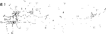
-Fig. 2 is a lateral plan of this identical systems;
-Fig. 3 is a suspension bracket of a hinge section of system illustrated in figures 1 and 2;
-Fig. 4 is the front elevation of this identical suspension bracket partly cut-away when deposit position;
-Fig. 5 is the longitudinal diagram of Hubei Province plate mechanism of system illustrated in figures 1 and 2;
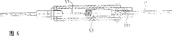
-Fig. 6 is the section-drawing along the partly cut-away of the line VI-VI among Fig. 5;
-Fig. 7 tube slightly shows the suspension bracket of Fig. 3 and Fig. 4 through out-of-date, the position of the side guide means of the hoist cable of system illustrated in figures 1 and 2;
-Fig. 8 shows these the identical guidance devices at the hoist cable guiding position;
-Fig. 9 is the planar view of hoist cable carrying roller system;
-Figure 10 is the lateral plan of system shown in Figure 9;
-Figure 11 is the planar view that one of fluid delivery system is implemented modification;
-Figure 12 is the lateral plan of system shown in Figure 11;
-Figure 13 is the front elevation of the hoist cable angle position detecting device of Figure 11 and system shown in Figure 12;
-Figure 14 is the planar view of device shown in Figure 13;
-Figure 15 is the planar view of another enforcement modification of fluid delivery system;
-Figure 16 is the lateral plan of system shown in Figure 15;
-Figure 17 is a planar view of implementing modification of the fluid delivery system of transportation of liquefied natural gas;
-Figure 18 is the enlarged drawing that is installed in the first kind hinge section in the system shown in Fig. 1,2,11,12,15 and 16;
-Figure 19 is the enlarged drawing that is installed in the second type hinges section in the system shown in Fig. 1,2,11,12,15 and 16;
-Figure 20 is the enlarged drawing that is installed in the first kind hinge section in the system shown in Figure 17; And
-Figure 21 is the enlarged drawing that is installed in the second type hinges section in the system shown in Figure 17.
Among Fig. 1 with 10 the expression independent production platform a part.Oil tanker 11 tightly ties up on the platform 10 by steel cable.The fluid delivery system 13 of one most preferred embodiment can be exploited out platform 10 according to the present invention, is crude oil herein, is transported on the oil tanker 11.
For this reason, system 13 comprises that one is installed in the support 14 on the platform, deposit 15 groups of the rigid pipe sections of conveyance fluid (being crude oil) here with suspention, these pipeline sections couple together by the hinge section 16,16 ' that is equipped with quarter bend tube and swivel joint to each other, with can from pipeline section 15 the deposit position that folding on the storage bracket 14 is suspending in midair be transformed into launch between platform 10 and the oil tanker 11, be suspended in the position on hoist cable or the load-bearing steel cable 17, with the conveying (described two positions shown in Fig. 2) of carrying out fluid.
Can clearlyer find out that from Figure 18 each hinge section 16 all has two quarter bend tubes 18, their ends are connecting an end of rigid pipe section 15, and its other end is connecting adjacent quarter bend tube 18 by swivel joint 19.When hinge section 16 unsettled on hoist cable the time (as shown in Figure 1), the axis approximate horizontal of described swivel joint 19, and perpendicular to hoist cable 17.When these pipeline sections 15 were in expanded position, this swivel joint 19 not only can make pipeline section 15 fit with the curve of hoist cable 17 in vertical plane surface, and these pipeline sections 15 are folded up again, left storage bracket in or deposited on the station 14 can folding.
In like manner, each hinge section 16 ' also is equipped with the swivel joint 19 ' of an axis horizontal between two quarter bend tubes 18 '.But between the end of a right angle bend pipe 18 ' and a rigid pipe section 15, the 3rd quarter bend tube 18 is housed also ".Described the 3rd quarter bend tube 18 " swivel joint 20 by axis approximate vertical when the expanded position is connected to adjacent quarter bend tube, makes the pipeline section 15 can sidesways like this.When conveyance fluid, these sidesways of pipeline section can make system adapt to rocking of oil tanker 11 and platform 10.In addition, reversing by additional swivel joint 21 of pipeline absorbs, and described joint 21 is the 3rd quarter bend tube 18 of hinge section 16 ' " and couple together with an end of these swivel joint 21 straight pipeline sections 15.
As shown in Figure 1, because these hinge section 16,16 ' are arranged, therefore on expanded position, pipeline section 15 can be positioned at hoist cable 17 both sides in turn.
Should also be noted that in this most preferred embodiment 1/4th hinge section is the swivel joint of axis normal.
For the length of these pipeline sections 15 according to the hoist cable 17 of tension between platform 10 and oil tanker 11, be suspended on storage bracket 14 and the hoist cable 17, some hanging devices also are equipped with.
As shown in Figure 2, described hanging device comprises some suspension brackets 22, and described suspension bracket is every two pipeline sections 15, is connected respectively on the swivel joint 19 or 19 ' of axis horizontal of a hinge section 16 or 16 '.
Fig. 3 and Fig. 4 illustrate in greater detail this class suspension bracket 22.
Shown in Fig. 3,4, each suspension bracket 22 all passes through an antifriction-bearing box 23 and links to each other with hinge section 16, and this antifriction-bearing box has an inner ring 24 and an outer ring 25, is embedded with ball 26 between the Internal and external cycle.Inner ring 24 is fixed on the outer end of adjacent swivel joint 19,25 ends that connecting the upright arm 27 of suspension bracket 22 by a loose pin hinge 28, outer ring.
The axis of this loose pin hinge 28 is roughly parallel to the bearing of trend of admitting passage 29, and this admits passage to be limited by clamp 30, is used for admitting hoist cable 17.
This clamp 30 fuses at that end and the arm 27 relative with the end that is being connected outer ring 25 of arm 27.It comprises two articulated jibs 31,32, and this two arm is pressed towards the clamped position of clamp 30 by spring 33, and described spring is installed on the arm 31 by rotation, and a bar 34 that passes by hole 35 remains between two arms 31,32 from the arm 32.
It shall yet further be noted that clamp 30 be herein crosswise fixed on arm 27, and can be from top clamping hoist cable 17.
Can find out that loose pin hinge 28 can allow hoist cable 17 and the malalignment of the pipeline that forms at the pipeline section 15 of expanded position.
Can find out also that in Fig. 4 each arm 31,32 also is equipped with roller 37a, 37b at it with that the relative end of end that clamps hoist cable 17.Each roller 37a, 37b roll engagement in guide rail 38a, the 38b of storage bracket 14.
When deposit position, the spacing of guide rail 38a, 38b is such: make clamp 30 overcome spring force and be maintained on the deployed position that when pipeline section 15 migration expanded positions, described clamp can be engaged on the hoist cable 17 like this.
Control system 39 (as Fig. 1,2) is installed on the storage bracket 14, is equipped with a hydraulic drive mechanism, this hydraulic drive mechanism or clamp 30 is engaged between guide rail 38a, the 38b, or discharge this clamp 30, it can be suspended on the hoist cable 17.
For suspension bracket 22 is suspended on the hoist cable 17 with constant spacing, control system is connecting a position transduser of constant pulling force transmission winch 40, and this winch is placed on the platform 10, and hoist cable 17 twines on it.
The length that hoist cable launches is measured by position transduser, and corresponding information is transferred to the control system 39 of operation in the following manner:
If-hoist cable 17 is in expansion process and reach preset space length, just discharge a clamp 30, so that it clamps hoist cable 17, thereby hinge section 16 or 16 ' is attached on this hoist cable 17;
If-hoist cable just twines on the winch 40, and a clamp 30 is arranged before control system 39, then the hydraulic drive mechanism of this control system snaps into clamp 30 between guide rail 38a, the 38b, and it is maintained on the deposit position between guide rail 38a, 38b.
During conveyance fluid between platform 10 and the oil tanker 11 whole, all use this running logic, during this period, interval between platform and the oil tanker or increase or reduction.
The transmission winch 40 of constant pulling force can impose on hoist cable 17 1 constant pulling force, so that the middle part of this hoist cable 17 keeps the sag of a constant.For this reason, winch 40 drives by a fluid motor that is under the constant pressure always.When oil tanker 11 leave or near the time, hoist cable 17 or be wrapped on the winch 40 or from winch launches; The variation of sag (weak) only is decided by the variation at span (interval between platform 10 and the oil tanker 11).
The hoist cable that is wrapped on this winch 40 is brought to storage bracket 14 places by 90 ° of track adjusting wheels 41, and this track adjusting wheel is installed on the pedestal 42 that is fixed on the platform 10.Storage bracket 14 also is installed on this pedestal 42 by antifriction-bearing box 43, can rotate in an orientation.
The one group of other pipeline section 45 that is hinged by swivel joint and bend pipe stretches along pedestal 42 to each other, supplies with crude oil with the pipeline that forms to pipeline section 15, and can follow storage bracket 14 around pedestal 42 rotations.
When expanded position, described pipeline is equipped with double valve fluid coupling 46 at oil tanker 11 those sides' the other end, to be connected to the house steward 47 on the oil tanker 11.
For hoist cable 17 and the pipeline section 15 that is fixed on the hoist cable are moved on the oil tanker 11 from platform 10, the winch 48 that is twining connecting strand 49 is installed on the deck of oil tanker 11.For drawing connecting strand 49 in platform 10 directions, so that it is fixed together with hoist cable 17, also be furnished with an additional winch 50 on the platform deck, hawser 51 just is wrapped on this winch.
As shown in Figure 5, an end of this hawser 51 has a hook ring 52, is used for hawser 51 is articulated on the joint 53 that is fixed on connecting strand 49 1 ends.
For winning over the back at connecting strand to platform 10 directions hoist cable 17 is fixed on the connecting strand 49, Hubei Province plate mechanism 54 is fixed on the end of hoist cable 17.When cable wire extended, two pull back spring 55a, 55b can be fixed on joint 53 between Hubei Province plate 56a, the 56b.Correspondingly, the pulling force of cable wire can make Hubei Province plate 56a, 56b tightly be stuck on the joint 53, because this joint when connection location, can support convex shoulder 57a, the 57b of each Hubei Province plate 56a, 56b, described like this Hubei Province plate can be towards its stop position direction rotation on joint 53.
In Fig. 5, also can find out a part of suspension bracket 58, it is installed in rotation in Hubei Province plate mechanism 54, and coupler 46 is fixed on (as Fig. 2) on this suspension bracket.
As shown in Figure 1 and Figure 2, first device that forms mechanical stops 59 is fixed on the storage bracket 14, and second device that forms mechanical stops 60 is installed on the oil tanker deck, near house steward 47.When not starting the expansion process of hoist cable 17 and pipeline section 15, form the lockable Hubei Province of first device plate mechanism 54 of hill holder 59, when hoist cable 17 was strained between platform 10 and oil tanker 11, second device that forms mechanical stops 60 then was used for this identical Hubei Province plate mechanism 54 of locking.
In the present embodiment, the tension force of hoist cable 17 imposes on pedestal 42 by track adjusting wheel 41.14 weight of bearing pipeline section 15 of storage bracket.Therefore, the described support 14 that can freely center on pedestal 42 rotation must be in line with hoist cable 17 and aim at.Realize this adjusting to a line by the side leading sheave shown in Fig. 7 to Figure 10.
Fig. 7 and Fig. 8 show one group of two pulley 61,62, and these two pulleys are installed in rotation on respectively on the back plate 63 by arm 64 and 65.
Described arm 64 and 65 is by two hydraulic actuators 67 and 68, and around common pivot 66 rotations, each hydraulic actuator is fixed on the back plate 63 on the one hand, is fixed on the other hand on one of two arms 64,65.
63 of back plates are fixed on the storage bracket 14.
Therefore, on position shown in Figure 8, pulley 61 and 62 contacts in hoist cable 17 both sides and its, the any mobile storage bracket 14 that all can cause of this hoist cable 17 is rotated on pedestal 42, so that storage bracket 14 and hoist cable 17, the axis of the fluid-transporting tubing of therefore going back and launching between platform 10 and oil tanker 11 is kept in-line.
Thus, storage bracket 14 automatic and hoist cable 17 aligned.
When suspension bracket 22 through out-of-date (as Fig. 7), pulley 61 and 62 is owing to hoist cable 17 is left in the running of hydraulic actuator 67 and 68.It is simple that this biliquid pressure is made the movable barrel type system architecture, and mechanical safety is good.
But but make all side guidings of any moment, and in fact, two groups of pulleys to be arranged at diverse location, described two groups of pulleys were dodged before suspension bracket 22 processes in turn.
Fig. 9 and 10 shows described two groups of pulleys of not being with its operating mechanism.From Fig. 9,10, can find out the first group of pulley 61,62 that also shows among Fig. 7 and Fig. 8, and at second group of pulley 61 ', 62 ' first group of pulley, 61,62 upstream positions, that be positioned at hoist cable 17 both sides.
Because the crank motion of oil tanker 11 when it loads the stage, suspension bracket 22 can stop on any point of this pulley guidance system, re-moving along a direction or other direction, even rock around a certain position indefinite.
Therefore, control system 39 is connecting a position detector, adjusting the order that assembly pulley is dodged and operated according to the position of detected suspension bracket 22.
Fig. 9 and Figure 10 also show the pulley 69-72 that supports pipeline section 15 weight in storage bracket 14 outlets.
These pulleys 69-72 connects together by two two of connecting rod 73-76, and con-rod only rotates again and is hinged on pulley 69-72 on the middle suspension rod 77 and 78 on the storage bracket 14.
Fluid delivery system moves in the following manner:
When fluid delivery system 13 did not put in place, pipeline section 15 was at punctured position, and promptly folding is suspended on the storage bracket 14.
When fluid delivery system 13 is installed, at first hawser 51 is for example drawn toward oil tanker 11 from platform simultaneously with steel cable 12.So the operating personal on the oil tanker 11 couples together this hawser and the end that is wrapped in the connecting strand 49 on the winch 48.
After connecting, hawser 51 is wound onto on its winch 50.It drives connecting strand 49 and launches from its winch 48.When the end of connecting strand 49 arrives storage bracket 14, the end of hoist cable 17 on its automatic engagement.Exactly, the joint 53 of connecting strand 49 is Hubei Province plate 56a, the 56b of Hubei Province plate machinery 54 separately, is fixed in this.Connecting strand 49 1 connects goes up hoist cable 17, and the connection winch 48 on the oil tanker 11 begins starting, and the hoist cable 17 and the pipeline section 15 that are fixed on successively on the storage bracket are pullled out from storage bracket 14.The constant pulling force that winch 40 applies is opposite with hoist cable 17 outbound courses, has limited the sag of the fluid delivery system 13 of suspention.22 on suspension bracket is fixed on the described hoist cable 17 with constant spacing.
When the end of hoist cable 17 arrived on the oil tanker, mechanical stop apparatus 60 lockings were lived Hubei Province plate mechanism 54.So, connecting winch 48 and stop, fluid coupling 46 connects the flange of going up house steward 47.
At this moment, the valve open of coupler 46, oil tanker 11 begin to load.
In whole loading process, according to platform 10 and oil tanker 11 distance at interval, pipeline section 15 or retraction or stretch out from storage bracket.
When platform and oil tanker were separated, operation order and sense of motion were just in time opposite.But still need the constant pulling force of reservation from platform 10.
Can find out that this fluid delivery system 13 can have big displacement in any direction.
In addition, use this system, fluid velocity is very fast, so feed flow is big, and can anti-effectively hydraulic impact.
Figure 11 has proposed a rotation follow-up mechanism of storage bracket to enforcement modification shown in Figure 14.
More precisely, Fig. 1 rotates follow-up system to the side guiding pulley system of hoist cable 17 shown in Figure 10 by one of storage bracket 14 and replaces, and this follow-up system comprises the rotational position detector 79 (as Figure 13,14) of a hoist cable 17 and centers on the follow-up mechanism 80 (as Figure 11) of the storage bracket 14 of pedestal 42 rotations.
Side direction at the hoist cable 17 of storage bracket 14 outlet is measured by the action roller 81 on this hoist cable 17.Because this action roller 81 is placed on the hinged support 82, this hinged support is installed on the adapter plate 83 on the storage bracket 14, so described action roller can be followed the sideway movement of hoist cable 17 by both heights compensation hinge 84a, 84b.
Hinged support 82 is also connecting a rotary encoder 85.
The output signal of 17 jiaos of positions of expression hoist cable of this coder is filtered, to eliminate rocking of hoist cable itself.This signal sends the fluid motor 86 of rotation follow-up mechanism 80 to, so that storage bracket 14 is by a rack rail system, main direction alignment with hoist cable 17, the gear of this rack rail system is installed on the output shaft of fluid motor 86, rack rails 87 is installed on the platform deck, in roller track 88 back of roller 44.
Aspect all the other, Figure 11 is identical with fluid delivery system 13 among Fig. 1 to Figure 10 in every respect to fluid delivery system 13 ' shown in Figure 14.
In Figure 15 and enforcement modification shown in Figure 16, fluid delivery system 13 " storage bracket 14 ' be rigidly attached on the platform 10.
Therefore oil tanker 11 is absorbed by the fluid-transporting tubing of hoist cable 17 and pipeline section 15 formation in the outlet of storage bracket 14 ' fully with respect to the sidesway of platform 10.
Therefore, fluid delivery system 13 " in the outlet of storage bracket 14 ', similar side guidance system 89 with reference to the hoist cable described in Fig. 7 to Figure 10 17 is arranged.
In addition, the hinge section of the swivel joint with axis approximate vertical of type shown in Figure 19 is installed in each suspension bracket 22 place.
Aspect all the other, this fluid delivery system 13 " operation scheme and Fig. 1 to shown in Figure 10 similar.
Note that Figure 15 and 16 does not illustrate the winch that is twining hawser.This winch identical with shown in other accompanying drawing for example can be placed in winch 50 back.
Figure 17 shows another embodiment of fluid delivery system.
This fluid delivery system 13 are used for liquefied natural gas is transported on the oil tanker 11 from platform 10.For this reason, it comprises second pipeline that pipeline section 15 ' forms, and forms steam flows back to platform 10 from oil tanker 11 pipeline.
Shown in Figure 20 and 21, the diameter of the pipeline section 15 ' of backflow steam is littler than the diameter of the pipeline section 15 of transportation of liquefied natural gas.
Because the temperature of transportation of liquefied natural gas is about-160 ℃, so all swivel joint that present embodiment adopts are low temperature swivel joint of Chicksan joint type.
In addition, for making two pipelines between platform 10 and oil tanker 11, launch simultaneously respective hinge section 16,16 abreast " between couple together by the horizontal hinge 90 shown in Figure 20 and 21.
In this respect, it should be noted that each hinge section 16 shown in Figure 21 " have only the swivel joint 91,91 ' of a unique axis approximate horizontal, described swivel joint 91,91 ' links to each other with the joint 92,92 ' of axis approximate vertical.
Identical among 16 of hinge section shown in Figure 20 and Figure 18.
Certainly, the present invention is not limited to the scope of above each embodiment.
It especially comprises all devices of the equivalent technologies that constitutes the above device, and their combination.
In addition, also can carry fluid except that crude oil, liquefied natural gas according to fluid delivery system of the present invention.In these fluids, autogas and condensed fluid are for example arranged.
Claims (15)
1. the system of conveyance fluid between the primary importance and the second place comprises:
The transmission winch (40) of one constant pulling force, this winch is used for being placed in described primary importance, and the hoist cable (17) that is used for straining between the described primary importance and the second place is wrapped in this above winch, and winch is suitable for imposing on hoist cable (17) one constant pulling force;
One storage bracket (14; 14 '), this support is used for being placed in primary importance (10), deposits rigid pipe section (15) with suspension, between these rigid pipe sections by being equipped with bend pipe (18,18 ', 18 ") and swivel joint (19,20,21; 91,92) hinge section (16,16 '; 16 ") hinged, with can be from pipeline section (15) in storage bracket (14; 14 ') deposit position that folding is suspending in midair on is transformed into and is suspended in the position that hoist cable (17) upward launches between the described primary importance and the second place, to carry out the conveying of fluid; And
Hanging device, they are according to the length of the hoist cable of straining between the described primary importance and the second place (17), in storage bracket (14; 14 ') or articulate some hinge section (16,16 ' on the hoist cable (17); 16 ").
2. system according to claim 1, it is characterized in that, hanging device comprises that is used for a hinge section (16,16 ') suspension bracket (22), clamp clamp (30) crosswise fixed of hoist cable (17) on each suspension bracket from the top, be fixed on the hoist cable (17) with this suspension bracket (22), in addition, this system comprises that also one connects winch (48), this winch is used for being placed on the described second place, is twining a connecting strand (49) above, and described connecting strand is suitable for linking to each other with hoist cable (17), be used for before conveyance fluid, hoist cable being moved to the described second place (11), and be fixed in this, or after having carried fluid, again hoist cable is retracted described primary importance (10), in these two processes, the transmission winch (40) of constant pulling force imposes on this hoist cable one constant pulling force all the time.
3. system according to claim 2, it is characterized in that, it comprises a winch (50), this winch is used for being placed in described primary importance (10) and locates, twining hawser (51) above, this hawser is used for linking to each other with connecting strand (49), links to each other with hoist cable (17) connecting strand is moved to primary importance (10).
4. according to claim 2 or 3 described systems, it is characterized in that, be suitable for Hubei Province plate mechanism (54) that connecting strand (49) one ends link to each other with hoist cable (17) is fixed on the end of described hoist cable (17), so that connecting strand (49) is fixed on the hoist cable (17).
5. system according to claim 4, it is characterized in that it comprises that one forms the device of mechanical stops, this device is used for being placed on the described second place (11), when hoist cable (17) is strained between two positions, but Hubei Province plate mechanism (54) is stated in its locking residence.
6. system according to claim 1 is characterized in that, it has a double valve fluid coupling (46) on an end pipeline section (15), and this device is used for being connected to a house steward (47) who is used for being installed on the second place (11), with conveyance fluid.
7. system according to claim 1 is characterized in that, is used for being articulated in the hinge section (16 ' on the hoist cable (17); 16 " at least a portion) comprises swivel joint (20 by an axis normal at the expanded position of pipeline section (15,15 '); 92) and the swivel joint (19 ', 21 of at least one axis horizontal; 91) combination of Gou Chenging.
8. system according to claim 1, it is characterized in that, hanging device comprises one group of suspension bracket (22), each suspension bracket has a clamp (30) from top clamping hoist cable (17), the clamp crosswise fixed is on suspension bracket one end, each suspension bracket all passes through a loose pin hinge (28) and is connected to a hinge section (16,16 '; 16 "), the parallel axes of described loose pin hinge is in the bearing of trend of the passage (29) of the admittance hoist cable (17) that is limited by clamp (30).
9. system according to claim 1 is characterized in that, hanging device comprises one group of suspension bracket (22), and each suspension bracket all passes through an antifriction-bearing box (23) and a hinge section (16,16 '; 16 ") link to each other.
10. according to claim 7 or 8 described systems, it is characterized in that storage bracket (14) is installed on the pedestal (42) on the primary importance (10), can rotate freely in an orientation, in addition, this system also comprises at least two group hoist cable (17) sides guiding pulley (61,62,61 ', 62 '), described assembly pulley is fixed on the storage bracket (14) at diverse location, is suitable for when the hanging device process in turn away from hoist cable (17).
11. according to claim 7 or 8 described systems, it is characterized in that, storage bracket (14), be installed on the pedestal (42) on the primary importance, can rotate freely in an orientation, in addition, this system also comprises a hoist cable (a 17) rotational position detector (79) and storage bracket (a 14) follow-up mechanism (80) around pedestal (42) rotation, the output signal sensitivity that this follow-up mechanism filters device after testing is so that storage bracket (14) is alignd with the main direction of hoist cable (17).
12. system according to claim 1, it is characterized in that, storage bracket (14 ') is rigidly connected to the pedestal (42) that is used for fixing at the primary importance place, be used for being articulated to each hinge section on the hoist cable (17) (16 ', 16 ") the expanded position of pipeline section (15) comprise by the swivel joint of an axis normal (20; 92) and the swivel joint (19 ' of at least one axis horizontal, 91) combination of Gou Chenging, this system comprises at least two group hoist cable (17) sides guiding pulley, and described assembly pulley is fixed on the storage bracket (14 ') at diverse location, is suitable for when the hanging device process in turn away from hoist cable (17).
13. system according to claim 1, it is characterized in that, hanging device comprises one group of suspension bracket (22), crosswise fixed has a clamp (30) from top clamping hoist cable (17) on each suspension bracket, each clamp (30) comprises two articulated jibs, this two arm is pressed towards the clamped position of clamp by a spring (33), each arm all is equipped with a roller (37a, 37b), described support comprise two guide rails (38a, 38b), each guide rail (38a, all be that a roller of clamp (30) has been determined a roller track 38b), and guide rail (38a, spacing 38b) is such: the deposit position in pipeline section (15), the effect that clamp (30) overcomes spring force is maintained at deployed position, like this, when pipeline section (15) migration expanded position, clamp is engageable to hoist cable (17).
14. system according to claim 13 is characterized in that, it is in storage bracket (14; 14 ') (38a, there is the pulley (69-72) of hoist cable (17) in downstream 38b) to guide rail.
15. the application of system according to claim 1, transportation of liquefied natural gas between the oil tanker (11) of the independent floating production platform (10) of determining primary importance and definite second place, described pipeline section (15) links to each other with other pipeline section (15 ') by hinge (90), to form two fluid-transporting tubings of parallel expansion between described two positions simultaneously, one of two pipelines are used for to oil tanker (11) transportation of liquefied natural gas, and another pipeline then makes steam flow back to platform (10).
Applications Claiming Priority (2)
| Application Number | Priority Date | Filing Date | Title |
|---|---|---|---|
| FR9909092A FR2796375B1 (en) | 1999-07-13 | 1999-07-13 | OFFSHORE LOADING SYSTEM BY SUSPENDED PIPING |
| FR99/09092 | 1999-07-13 |
Publications (2)
| Publication Number | Publication Date |
|---|---|
| CN1420841A CN1420841A (en) | 2003-05-28 |
| CN1223507C true CN1223507C (en) | 2005-10-19 |
Family
ID=9548059
Family Applications (1)
| Application Number | Title | Priority Date | Filing Date |
|---|---|---|---|
| CNB008102147A Expired - Fee Related CN1223507C (en) | 1999-07-13 | 2000-07-07 | Offshore loading system by suspended piping |
Country Status (16)
| Country | Link |
|---|---|
| US (1) | US6719008B1 (en) |
| EP (1) | EP1196347B1 (en) |
| JP (1) | JP3987721B2 (en) |
| KR (1) | KR100643554B1 (en) |
| CN (1) | CN1223507C (en) |
| AT (1) | ATE261910T1 (en) |
| AU (1) | AU6296300A (en) |
| CA (1) | CA2378652C (en) |
| DE (1) | DE60009073T2 (en) |
| ES (1) | ES2218188T3 (en) |
| FR (1) | FR2796375B1 (en) |
| NO (1) | NO323762B1 (en) |
| PT (1) | PT1196347E (en) |
| RU (1) | RU2246443C2 (en) |
| WO (1) | WO2001004041A2 (en) |
| ZA (1) | ZA200200023B (en) |
Families Citing this family (33)
| Publication number | Priority date | Publication date | Assignee | Title |
|---|---|---|---|---|
| FR2831514B1 (en) * | 2001-10-30 | 2004-03-12 | Eurodim Sa | SYSTEM FOR TRANSPORTING A FLUID BETWEEN A TRANSPORT VESSEL AND A STORAGE STATION SUCH AS A STORAGE VESSEL |
| FR2837190B1 (en) * | 2002-03-15 | 2004-10-08 | Eurodim Sa | SYSTEM FOR TRANSFERRING A FLUID PRODUCT, ESPECIALLY LIQUEFIED NATURAL GAS, BETWEEN A FLUID TRANSPORT VESSEL AND A STORAGE STATION |
| FR2854156B1 (en) * | 2003-04-23 | 2007-03-09 | Fmc Technologies Sa | ARTICULATED-ARM ASSEMBLY COMPRISING A CONNECTING CABLE FOR LOADING AND UNLOADING PRODUCTS, IN PARTICULAR FLUID PRODUCTS |
| TW200732292A (en) | 2006-02-01 | 2007-09-01 | Shell Int Research | A method of treating an aldehyde mixture, use of the treated aldehyde, and an alcohol |
| EP2116527A4 (en) | 2007-01-23 | 2011-09-14 | Fujifilm Corp | Oxime compound, photosensitive composition, color filter, method for production of the color filter, and liquid crystal display element |
| RU2440533C2 (en) * | 2007-09-27 | 2012-01-20 | Йоханнес Герхардус Йозеф БЬЮИЦ | Method to install pipeline in circle on water in horizontal plane |
| FR2927322B1 (en) * | 2008-02-08 | 2010-03-05 | Fmc Technologies Sa | DEVICE FOR DIRECT CONTROL, PARTICULARLY PROPORTIONAL AND / OR LOADING AND / OR UNLOADING FLUIDS |
| US20090232664A1 (en) * | 2008-03-12 | 2009-09-17 | General Electric | Permanent magnet motor for subsea pump drive |
| FR2941434B1 (en) | 2009-01-27 | 2015-05-01 | Fmc Technologies Sa | SYSTEM FOR TRANSFERRING A FLUID PRODUCT AND ITS IMPLEMENTATION |
| NO335242B1 (en) * | 2010-09-01 | 2014-10-27 | Aker Pusnes As | load Lange |
| KR101751829B1 (en) * | 2010-11-23 | 2017-06-29 | 대우조선해양 주식회사 | Fluid transfer apparatus |
| FR2967990B1 (en) | 2010-11-30 | 2014-11-28 | Saipem Sa | SUPPORT INSTALLED AT SEA EQUIPPED WITH A CONNECTION DEVICE AND VALVES USEFUL FOR PURGING FLEXIBLE CONDUITS |
| FR2968058B1 (en) | 2010-11-30 | 2012-12-28 | Saipem Sa | SUPPORT AT SEA EQUIPPED WITH A DEVICE FOR STORING AND GUIDING FLEXIBLE CONDUITS USEFUL FOR THE TRANSFER AT SEA OF PETROLEUM PRODUCTS |
| US9605772B2 (en) * | 2012-05-15 | 2017-03-28 | Schlumberger Technology Corporation | Quick disconnect system |
| AU2013100491B4 (en) * | 2012-09-03 | 2014-01-16 | Seacaptaur Ip Ltd | Vessel |
| CN103423585B (en) * | 2013-08-23 | 2015-08-26 | 连云港远洋流体装卸设备有限公司 | The pipeline steering equipment of loop wheel machine formula cryogen filing provision peculiar to vessel |
| US9598152B2 (en) * | 2014-04-01 | 2017-03-21 | Moran Towing Corporation | Articulated conduit systems and uses thereof for fluid transfer between two vessels |
| KR20160128661A (en) | 2015-04-29 | 2016-11-08 | 대우조선해양 주식회사 | Fluid transfer system |
| CN105151237B (en) * | 2015-10-08 | 2017-03-29 | 中国海洋石油总公司 | Suitable for cylinder type or the outer defeated system of polygon FPSO/FDPSO |
| RU168478U1 (en) * | 2016-03-09 | 2017-02-06 | Федеральное государственное унитарное предприятие "Крыловский государственный научный центр" | DEVICE FOR NON-CURRENT LOAD-UNLOADING OF HYDROCARBON RAW MATERIALS ON TRANSPORT SHIP |
| DK3293429T3 (en) | 2016-09-09 | 2019-09-09 | Technip France | Deflector intended for conducting a lead and associated guiding device |
| KR101894358B1 (en) * | 2017-03-30 | 2018-09-04 | 삼성중공업 주식회사 | Tandem offloading system |
| KR101885263B1 (en) * | 2017-05-15 | 2018-08-03 | 삼성중공업 주식회사 | Transfer apparatus using loading hose |
| CN107521626A (en) * | 2017-07-20 | 2017-12-29 | 武汉船用机械有限责任公司 | A kind of flexible pipe extension and retraction system |
| NO345782B1 (en) * | 2017-09-06 | 2021-08-09 | Connect Lng As | Tie-in system and fluid transfer system comprising such a tie-in system |
| FR3074137B1 (en) * | 2017-11-24 | 2022-01-21 | Fmc Tech Sa | DEVICE FOR TRANSFERRING CRYOGENIC PRODUCTS BETWEEN A FLOATING STRUCTURE AND A FIXED OR FLOATING STRUCTURE |
| FR3075755A1 (en) * | 2017-12-22 | 2019-06-28 | Fmc Technologies Sa | CRYOGENIC PRODUCT TRANSFER SYSTEM BETWEEN TWO SHIPS SIDED SIDE |
| CN108343783B (en) * | 2018-02-28 | 2019-06-28 | 中国二十冶集团有限公司 | The installation method and hanging apparatus of high-altitude large-diameter pipeline under complex environment |
| CN108488485B (en) * | 2018-04-03 | 2020-01-03 | 航天晨光股份有限公司 | Ship large-pipe-diameter water delivery hose suspension device and installation method thereof |
| SG11202113054QA (en) * | 2019-05-29 | 2021-12-30 | Sofec Inc | Systems for handling one or more elongated members and methods for using same |
| CN110630819B (en) * | 2019-10-26 | 2021-05-07 | 中国海洋石油集团有限公司 | Dock oil hose stinger |
| CN112061318B (en) * | 2020-09-04 | 2022-07-05 | 中船黄埔文冲船舶有限公司 | Liquid cargo receiving auxiliary device |
| KR102502687B1 (en) * | 2022-09-15 | 2023-02-21 | 주식회사 디타스 | Winding maintenance system and delivery system of winch system for submarines |
Family Cites Families (9)
| Publication number | Priority date | Publication date | Assignee | Title |
|---|---|---|---|---|
| FR1415279A (en) * | 1964-11-28 | 1965-10-22 | Parker Hannifin Corp | Installation for the transshipment of a liquid, in particular from boat to boat |
| GB1393369A (en) * | 1971-11-16 | 1975-05-07 | Duggan J D | Collapsible booms |
| GB1592073A (en) * | 1977-02-08 | 1981-07-01 | Fmc Corp | Fluid loading systems |
| US4299261A (en) * | 1978-12-11 | 1981-11-10 | Fmc Corporation | Offshore loading system |
| FR2448496A1 (en) | 1979-02-12 | 1980-09-05 | Fmc Europe | ARTICULATED ARM FOR LOADING AND UNLOADING PRODUCTS, PARTICULARLY FLUID PRODUCTS |
| FR2474012B2 (en) | 1979-05-28 | 1986-01-31 | Fmc Europe | COUPLING AND TRANSFER MEANS FOR ARTICULATED LOADING ARMS FOR TRANSFERRING FLUIDS |
| DE2945768A1 (en) | 1979-11-13 | 1981-05-27 | Hans 8000 München Tax | CHARGING SYSTEM FOR LIQUID CARGOES |
| FR2793235B1 (en) * | 1999-05-03 | 2001-08-10 | Fmc Europe | ARTICULATED DEVICE FOR TRANSFERRING FLUID AND LOADING CRANE COMPRISING SUCH A DEVICE |
| FR2794738B1 (en) * | 1999-06-14 | 2002-02-01 | Fmc Europe | ARTICULATED ARM FOR TRANSFER OF FLUID PRODUCTS WITH SPRING BALANCING WITH A LARGE TRAVEL |
-
1999
- 1999-07-13 FR FR9909092A patent/FR2796375B1/en not_active Expired - Fee Related
-
2000
- 2000-07-07 PT PT00949684T patent/PT1196347E/en unknown
- 2000-07-07 EP EP00949684A patent/EP1196347B1/en not_active Expired - Lifetime
- 2000-07-07 RU RU2002103385A patent/RU2246443C2/en not_active IP Right Cessation
- 2000-07-07 AU AU62963/00A patent/AU6296300A/en not_active Abandoned
- 2000-07-07 KR KR1020027000434A patent/KR100643554B1/en not_active IP Right Cessation
- 2000-07-07 WO PCT/FR2000/001978 patent/WO2001004041A2/en active IP Right Grant
- 2000-07-07 US US10/030,858 patent/US6719008B1/en not_active Expired - Fee Related
- 2000-07-07 JP JP2001509663A patent/JP3987721B2/en not_active Expired - Fee Related
- 2000-07-07 CA CA 2378652 patent/CA2378652C/en not_active Expired - Fee Related
- 2000-07-07 ES ES00949684T patent/ES2218188T3/en not_active Expired - Lifetime
- 2000-07-07 CN CNB008102147A patent/CN1223507C/en not_active Expired - Fee Related
- 2000-07-07 AT AT00949684T patent/ATE261910T1/en not_active IP Right Cessation
- 2000-07-07 DE DE2000609073 patent/DE60009073T2/en not_active Expired - Fee Related
-
2002
- 2002-01-02 ZA ZA200200023A patent/ZA200200023B/en unknown
- 2002-01-11 NO NO20020136A patent/NO323762B1/en not_active IP Right Cessation
Also Published As
| Publication number | Publication date |
|---|---|
| AU6296300A (en) | 2001-01-30 |
| US6719008B1 (en) | 2004-04-13 |
| CN1420841A (en) | 2003-05-28 |
| NO20020136L (en) | 2002-03-11 |
| NO20020136D0 (en) | 2002-01-11 |
| FR2796375A1 (en) | 2001-01-19 |
| EP1196347A2 (en) | 2002-04-17 |
| NO323762B1 (en) | 2007-07-02 |
| CA2378652A1 (en) | 2001-01-18 |
| WO2001004041A2 (en) | 2001-01-18 |
| PT1196347E (en) | 2004-08-31 |
| DE60009073T2 (en) | 2004-11-04 |
| CA2378652C (en) | 2009-12-22 |
| DE60009073D1 (en) | 2004-04-22 |
| JP2003511284A (en) | 2003-03-25 |
| KR20020035834A (en) | 2002-05-15 |
| RU2246443C2 (en) | 2005-02-20 |
| ZA200200023B (en) | 2003-07-28 |
| FR2796375B1 (en) | 2001-10-12 |
| ATE261910T1 (en) | 2004-04-15 |
| ES2218188T3 (en) | 2004-11-16 |
| KR100643554B1 (en) | 2006-11-10 |
| WO2001004041A3 (en) | 2002-09-26 |
| EP1196347B1 (en) | 2004-03-17 |
| JP3987721B2 (en) | 2007-10-10 |
Similar Documents
| Publication | Publication Date | Title |
|---|---|---|
| CN1223507C (en) | Offshore loading system by suspended piping | |
| RU2541034C2 (en) | Fluid product transportation system and methods for its implementation | |
| CN1292976C (en) | Assembly with articulated arm for loading and unloading products, in particular fluid products | |
| CN101156013B (en) | Marine pipelaying system for installing an offshore pipeline having one or more accessories | |
| US20040237869A1 (en) | Connector for articulated hydrocarbon fluid transfer arm | |
| RU2580488C2 (en) | Balanced loading hose without base for conveying fluid product | |
| AU2007278210B2 (en) | Deep water hydrocarbon transfer system | |
| EP1817475B1 (en) | A hybrid riser system | |
| KR20130085048A (en) | Device for transferring fluid from a marine mounting | |
| AU2011214352B2 (en) | Method of laying a hybrid pipeline on hte seabed | |
| CN110410580B (en) | Laying device for deepwater flexible submarine pipeline | |
| US4190090A (en) | Equipment serving to connect oil-tankers to marine towers | |
| US10946938B2 (en) | Coupling system for transfer of hydrocarbons at open sea | |
| AU2010255883B2 (en) | Pipe-laying vessel | |
| FR2960208A1 (en) | SURFACE BONDING SYSTEM COMPRISING A FLEXIBLE DRIVING GUIDE STRUCTURE | |
| US20140008076A1 (en) | Riser | |
| AU2014270079A1 (en) | Apparatus for launch and recovery of flexible hose and method of use | |
| CN110506176B (en) | System, apparatus and method | |
| SU317563A1 (en) | N.A. Stetsenko | |
| RU97109361A (en) | METHOD FOR SINGLE SHIELDING OF VESSELS ON THE OPEN SEA AND DEVICE FOR ITS IMPLEMENTATION | |
| BE623180A (en) |
Legal Events
| Date | Code | Title | Description |
|---|---|---|---|
| C06 | Publication | ||
| PB01 | Publication | ||
| C10 | Entry into substantive examination | ||
| SE01 | Entry into force of request for substantive examination | ||
| C14 | Grant of patent or utility model | ||
| GR01 | Patent grant | ||
| C17 | Cessation of patent right | ||
| CF01 | Termination of patent right due to non-payment of annual fee |
Granted publication date: 20051019 Termination date: 20110707 |