CN1223103C - Apparatus and method for transmitting TFCI bits for hard split mode in a CDMA mobile communication system - Google Patents
Apparatus and method for transmitting TFCI bits for hard split mode in a CDMA mobile communication system Download PDFInfo
- Publication number
- CN1223103C CN1223103C CNB028027094A CN02802709A CN1223103C CN 1223103 C CN1223103 C CN 1223103C CN B028027094 A CNB028027094 A CN B028027094A CN 02802709 A CN02802709 A CN 02802709A CN 1223103 C CN1223103 C CN 1223103C
- Authority
- CN
- China
- Prior art keywords
- code
- value
- multiplier
- tfci
- encoder
- Prior art date
- Legal status (The legal status is an assumption and is not a legal conclusion. Google has not performed a legal analysis and makes no representation as to the accuracy of the status listed.)
- Expired - Fee Related
Links
Images


Classifications
-
- H—ELECTRICITY
- H04—ELECTRIC COMMUNICATION TECHNIQUE
- H04L—TRANSMISSION OF DIGITAL INFORMATION, e.g. TELEGRAPHIC COMMUNICATION
- H04L1/00—Arrangements for detecting or preventing errors in the information received
- H04L1/004—Arrangements for detecting or preventing errors in the information received by using forward error control
- H04L1/0056—Systems characterized by the type of code used
- H04L1/0057—Block codes
-
- H—ELECTRICITY
- H03—ELECTRONIC CIRCUITRY
- H03M—CODING; DECODING; CODE CONVERSION IN GENERAL
- H03M7/00—Conversion of a code where information is represented by a given sequence or number of digits to a code where the same, similar or subset of information is represented by a different sequence or number of digits
- H03M7/14—Conversion to or from non-weighted codes
-
- H—ELECTRICITY
- H04—ELECTRIC COMMUNICATION TECHNIQUE
- H04B—TRANSMISSION
- H04B1/00—Details of transmission systems, not covered by a single one of groups H04B3/00 - H04B13/00; Details of transmission systems not characterised by the medium used for transmission
- H04B1/69—Spread spectrum techniques
- H04B1/707—Spread spectrum techniques using direct sequence modulation
-
- H—ELECTRICITY
- H04—ELECTRIC COMMUNICATION TECHNIQUE
- H04J—MULTIPLEX COMMUNICATION
- H04J13/00—Code division multiplex systems
-
- H—ELECTRICITY
- H04—ELECTRIC COMMUNICATION TECHNIQUE
- H04J—MULTIPLEX COMMUNICATION
- H04J13/00—Code division multiplex systems
- H04J13/0007—Code type
- H04J13/004—Orthogonal
- H04J13/0048—Walsh
-
- H—ELECTRICITY
- H04—ELECTRIC COMMUNICATION TECHNIQUE
- H04J—MULTIPLEX COMMUNICATION
- H04J13/00—Code division multiplex systems
- H04J13/10—Code generation
-
- H—ELECTRICITY
- H04—ELECTRIC COMMUNICATION TECHNIQUE
- H04L—TRANSMISSION OF DIGITAL INFORMATION, e.g. TELEGRAPHIC COMMUNICATION
- H04L1/00—Arrangements for detecting or preventing errors in the information received
- H04L1/004—Arrangements for detecting or preventing errors in the information received by using forward error control
- H04L1/0056—Systems characterized by the type of code used
- H04L1/0067—Rate matching
- H04L1/0068—Rate matching by puncturing
- H04L1/0069—Puncturing patterns
-
- H—ELECTRICITY
- H04—ELECTRIC COMMUNICATION TECHNIQUE
- H04L—TRANSMISSION OF DIGITAL INFORMATION, e.g. TELEGRAPHIC COMMUNICATION
- H04L1/00—Arrangements for detecting or preventing errors in the information received
- H04L1/004—Arrangements for detecting or preventing errors in the information received by using forward error control
- H04L1/0072—Error control for data other than payload data, e.g. control data
-
- H—ELECTRICITY
- H04—ELECTRIC COMMUNICATION TECHNIQUE
- H04J—MULTIPLEX COMMUNICATION
- H04J13/00—Code division multiplex systems
- H04J13/10—Code generation
- H04J13/102—Combining codes
-
- H—ELECTRICITY
- H04—ELECTRIC COMMUNICATION TECHNIQUE
- H04L—TRANSMISSION OF DIGITAL INFORMATION, e.g. TELEGRAPHIC COMMUNICATION
- H04L1/00—Arrangements for detecting or preventing errors in the information received
- H04L1/0001—Systems modifying transmission characteristics according to link quality, e.g. power backoff
- H04L1/0023—Systems modifying transmission characteristics according to link quality, e.g. power backoff characterised by the signalling
- H04L1/0025—Transmission of mode-switching indication
Landscapes
- Engineering & Computer Science (AREA)
- Computer Networks & Wireless Communication (AREA)
- Signal Processing (AREA)
- Theoretical Computer Science (AREA)
- Mobile Radio Communication Systems (AREA)
- Compression, Expansion, Code Conversion, And Decoders (AREA)
- Detection And Prevention Of Errors In Transmission (AREA)
- Error Detection And Correction (AREA)
Abstract
An encoding method and apparatus for a DCH (Dedicated Channel) encoder and a DSCH (Downlink Shared Channel) encoder in a transmitter for a mobile communication system including the DCH encoder for encoding k bits among 10 input TFCI (Transport Format Combination Indicator) bits and the DSCH encoder for encoding remaining (10-k) bits among the input TFCI bits. The method comprises generating, by the DCH encoder, a first coded bit stream by encoding the k input bits into 32 bits, and outputting a (3k+1)-bit stream by puncturing the first coded bit stream according to a specific mask pattern corresponding to the k value; and generating, by the DSCH encoder, a second coded bit stream by encoding the (10-k) input bits into 32 bits, and outputting a 3(10-k)+1 bit stream by puncturing the second coded bit stream according to a specific mask pattern corresponding to the (10-k) value.
Description
Technical field
The present invention relates generally to asynchronous CDMA (code division multiple access) mobile communication system, relate in particular in asynchronous CDMA mobile communications system, in the equipment and the method that are sent in TFCI (transport format combination indicator) position of using during data send on the downlink sharied signal channel.
Background technology
In general, downlink sharied signal channel (DSCH) by several users with the time be divided into the basis and share.The DSCH channel is to interrelate with the dedicated channel that is used for each user (DCH) to set up.DCH DPCH (DPCH) go up to send and DPCH with the time be divided into the basis by combination Dedicated Physical Control Channel (DPCCH) and Dedicated Physical Data Channel (DPDCH) formation.
DSCH go up to send and is used for sending on the DPCCH of channel control information at DPCH of PDSCH at physical down link sharing channel (PDSCH).The control information that sends on DPCCH comprises and following relevant information: (i) control is from the TPC (transmission power control commands) of the up-link transmit power of UE (subscriber equipment); (ii) be used for Pilot (pilot tone) field that channel variation is estimated, transmitted power is measured and the slot synchronization from the Node B to UE is obtained; (iii) TFCI (transport format combination indicator).In this information, TPC and Pilot are used in reference to information characteristic (for example, the combination of rate of information transmission and different information that is shown in DSCH and the last data that send of DPCCH as physics control information and the TFCI of PDSCH and DPCH, that is the combination of voice messaging and grouping information).
As mentioned above, TFCI, the control information of the information characteristic of the data that indication sends on physical channel DSCH and DPCCH has the length of 10-position, and is encoded into 32 positions.That is to say that the information of relevant data amount is with 10 bit representations, and, 10-position information is encoded into 30 positions, on physical channel, send.
TFCO according to following in the 3GPP that is used for UMTS (Universal Mobile Telecommunications System (Universal Mobile Tele-communication System)) (the 3rd generation partner plan (3
RdGeneration Partner-shipProject) method of regulation sends on physical channel in the technical specification 25.212.
a
kThe k information bit (0≤k≤9) of=transmission combined information
b
lThe l bits of coded (0≤l≤9) of=transmission combined information
d
mThe m of=transmission combined information sends bits of coded
a
kBe meant and be shown in the 10-position information that DPDCH goes up speed, type and the combination of the data that send, b
lBy passing through coding a
k32 bits of coded that obtain are formed, and d
mBe on DPCCH, to send b
lThe transmission bits of coded.Here, value m is the variable that changes with condition.
Determine d
mThe condition of the number of position is to determine according to the data rate of the sending mode of DPCCH and DPCH.The sending mode of DPCCH comprises normal transmission mode and compression sending mode.The compression sending mode is used in the UE that contains a RF (radio frequency) transceiver plan on another frequency band, to measure in.The transmission on current frequency band is supspended in operation under the compression sending mode, and UE can be measured on another frequency band.The data that will send in sending the termination interval are just in time compressed before the interval is ended in transmission and afterwards.
" data rate of DPCH " determines d
mOne of condition of the number of position refers to the physical data speed of DPCH, and determines according to spreading factor (SF).In the 3GPP of current mobile communication standard, the scope of the scope of SF from 512 to 4 and data rate is from 15Kbps to 1920Kbps.Along with SF is more and more higher, data rate is more and more lower.d
mThe reason determined according to the data rate of DPCH of number of position is to be the variable that the data rate with DPCH changes because send the size (or length) of TFCI field of the TFCI position of DPCCH.
For being used for determining d
mThe d of each transmission of condition
mThe number of position is calculated as follows.
A1. normal transmission mode, the data rate of DPCH is lower than 60Kbps
Be used for determining d
mUnder the situation of the condition A1 of the number of position, d
mThe number of position becomes 30.In the 3GPP standard, the basic transmission unit (BTU) of physical channel is a radio frame.Radio frame has the length of 10ms, is made up of 15 time slots.Each time slot contains the field that is useful on transmission TFCI.In the situation of A1, each time slot contains 2 TFCI and sends field, and like this, the TFCI that can send in a radio frame sends code bit d
mNumber become 30.Therefore, although based on information bit a
kBits of coded b
lNumber become 32, still because the restriction of the number of the actual TFCI field that sends, latter two transmission combined information position b
30And b
31Do not send.
A1. normal transmission mode, the data rate of DPCH is higher than 60Kbps
Be used for determining d
mUnder the situation of the condition A2 of the number of position, the length of TFCI field becomes 8 positions in the time slot, and, the d that in a radio frame, can on DPCCH, send
mSum become 120.Work as d
mSum be 120 o'clock, repeat to send b by following
l
d
0(b
0)、...、d
31(b
31)、d
32(b
0)、...、d
63(b
31)、...、d
96(b
0)、...、d
119(b
23)
In the situation of A2, the 0th to 23b
lRepeat to send 4 times and the 24th to 31b
lRepeat to send 3 times.
A3. compress sending mode, the data rate of DPCH is lower than 60Kbps or equals 120Kbps
Be used for determining d
mUnder the situation of the condition A3 of the number of position, the length of TFCI field becomes 4 positions in the time slot, and the number of the TFCI that can send in a radio frame is the variable that changes with the number that is used in the time slot in the compression sending mode.Under the compression sending mode, the scope that sends the number of ending time slot is from minimum 1 to maximum 7, and d
mThe number of position is between 32 and 56.Send bits of coded d
mNumber be limited to maximum 32, thereby the d that is changing
mLast transmission all the 0th to 31b
lThe position is at other d
mOn do not send b
l
A4. compress sending mode, the data rate of DPCH is higher than 120Kbps or equals 60Kbps
Be used for determining d
mUnder the situation of the condition A4 of the number of position, the length of TFCI field becomes 16 positions in the time slot, and the number of the TFCI that can send in a radio frame is the variable that changes with the number that is used in the time slot in the compression sending mode.Under the compression sending mode, the number that sends the termination time slot is from minimum 1 to maximum 7, and d
mThe number of position is between 128 and 244.Send bits of coded d
mNumber be limited to maximum 128, thereby the d that is changing
mOn repeat to send the 0th to 31b
l Position 4 times is at other d
mOn do not send b
l
In the compression sending mode of A3 and A4, d
mThe position is arranged in from sending and ends in the interval far away as far as possible at interval, makes to send d
mThe position reliability reaches maximum.
When A1, A2, A3 and A4 condition are used in the transmission combination of TFCI indication DPCH and type.During sending, TFCI is divided into TFCI that is used for DSCH and the method that is used for the TFCI of DPCH and can be divided into two kinds of independent solutions.
First method is the method that is used for cutting apart firmly pattern (HSM (hard split mode)), and second method is the method that is used for logical division pattern (LSM (logical split mode)).
The TFCI that the TFCI that is used for DCH is called as a TFCI (field 1) or a TFCI and is used for DSCH is called as TFCI (field 2) or the 2nd TFCI.
In the LSM method, utilize TFCI (field 1) and the TFCI (field 2) of (32,10) filial generation coding of second order Reed-Miu Le (Reed-Muller) sign indicating number as a field.The 10-position TFCI information of TFCI (field 1) and the different ratios of TFCI (field 2) expression, and, before sending,, utilize a block code according to A1, A2, A3 and A4 condition, that is, and 10 information bits of (32,10) filial generation of second order Reed-Miu Le sign indicating number coding.The ratio of TFCI (field 1) and TFCI (field 2) comprises 1: 9,2: 8,3: 7,4: 6,5: 5,6: 4,7: 3,8: 2 and 9: 1.
In the HSM method, utilize 5 positions to represent TFCI (field 1) and TFCI (field 2) respectively regularly, and, utilize (16,5) bi-orthogonal codes to export each information, then, according to A1, A2, A3 and A4 condition, alternately send 16 positions that are used for TFCI (field 1) and TFCI (field 2).
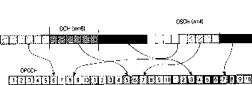
Fig. 1 has shown the structure based on the transmitter of traditional HSM method.With reference to Fig. 1, (16,5) bi-orthogonal coded device 100 is encoded into 16 code symbols to the 5-position TFCI (field 1) that is used for DCH, and 16 code symbols are offered multiplexer 110.Simultaneously, (16,5) bi-orthogonal coded device 105 is encoded into 16 code symbols to the 5-position TFCI (field 2) that is used for DSCH, and 16 code symbols are also offered multiplexer 110.Then, multiplexer 110 time division multiplexings are from 16 code symbols of encoder 100 with from 16 code symbols of encoder 105, and output is through 32 code elements after arranging.Multiplexer 120 time division multiplexings are from 30 code elements and other signal of multiplexer 110 output, and its output is offered expander 130.The extended code that expander 130 utilizes extended code generator 135 to provide is expanded the output signal of multiplexer 120.The scrambled code scrambling spread signal that scrambler 140 utilizes scrambled code generator 145 to provide.
Fig. 2 has shown the HSM method for definition in 3GPP (third generation partner plan), the general process of exchange of signaling message and data between Node B and RNC (radio network controller).3GPPRAN (radio access network) is by RNC (radio network controller), be made up of the Node B and the UE (subscriber equipment) of RNC control.RNC Control Node B, Node B is used as terminal as base station and UE.According to the relation of UE, RNC can be divided into SRNC (service radio network controller) and CRNC (control radio network controller).SRNC, the RNC of registration UE, data and control UE that processing will send to UE and receive from UE.CRNC, the RNC of current connection UE is connected UE with SRNC.
With reference to Fig. 2, if generate the transmission data of DSCH, the radio link controller (RLC) 11 of SRNC (Serving RNC) 10 sends to the DSCH data MAC-D (media interviews control-dedicated channel) 13 of SRNC 10 in step 101.The primitive of Fa Songing is MAC-D-Data-REQ this moment.In step 102, the MAC-D of SRNC 10 13 sends to the DSCH data that receive from RLC 11 MAC-C/SH (MAC-public/shared channel) 21 of CRNC (control RNC) 20.The primitive of Fa Songing is MAC-C/SH-Data-REQ this moment.In step 103, the MAC-C/SH 21 of CRNC 20 determines (arrangements) transmitting time from the DSCH data of MAC-D 13 receptions of SRNC 10 in step 102, then, the DSCH data TFI relevant with it (transport format indicator) sent to the Node B L1 of (hereinafter term " Node B " being called the base station) (layer 1) 30 together.The primitive of Fa Songing is MPHY-Data-REQ this moment.In step 104, the MAC-D 13 of SRNC 10 sends to the transmission data of the DCH TFI relevant with it L1 30 of Node B.The primitive of Fa Songing is MPHY-Data-REQ this moment.Data that send in step 103 and the data independence that sends in step 104, the L1 30 of Node B generates the TFCI that is divided into the TFCI that is used for DCH and is used for the TFCI of DSCH.In step 103 and 104, data and TFI utilize data framing protocol to send.Receive in step 103 and 104 after data and the TFI, in step 105, the L1 30 of Node B goes up at physics DSCH (PDSCH) the DSCH data is sent to UE (subscriber equipment; Hereinafter term " UE " is called travelling carriage) 40 L1 41.After this, in step 106, the L1 30 of Node B utilizes DPCH TFCI to be sent to the L1 41 of UE 40.The L1 30 of Node B is used for the field of DCH and DSCH, sends the TFCI that utilizes the TFI generation that receives in step 103 and 104.
Fig. 3 has shown the method for LSM, the general process of exchange of signaling message and data between Node B and RNC.With reference to Fig. 3, if generate the DSCH data that will send, the RLC 301 of RNC 300 sends to the DSCH data MAC-D 303 of RNC 300 in step 201.The primitive of Fa Songing is MAC-D-Data-REQ this moment.In case receive the DSCH data from RLC 301, MAC-D 303 just sends to MAC-C/SH (MAC-public/shared channel) 305 to the DSCH data in step 202.The primitive of Fa Songing is MAC-C/SH-Data-REQ this moment.In case receive the DSCH data, MAC-C/SH 305 just determines the transmitting time of (arrangement) DSCH data in step 203, then, the TFCI that interrelates with the DSCH data is sent to MAC-D 303.In step 203 TFCI is sent to after the MAC-D 303, MAC-C/SH 305 sends to the DSCH data L1 307 of Node B in step 204.The DSCH data are to send in the time of determining (arrangement) in step 203.In case receive the TFCI that is used for DSCH that sends from MAC-C/SH 305 in step 203, MAC-D303 just is identified for the TFIC of DSCH in step 205, and TFCI is sent to the L1 307 of Node B.The primitive of Fa Songing is MPHY-Data-REQ this moment.After having sent the TFCI that is used for DSCH, MAC-D 303 is identified for the TFCI of DCH in step 206, and the DCH data with being used for the L1 307 that DCHTFCI sends to Node B.The primitive of Fa Songing is MPHY-Data-REQ this moment.The DSCH data that send in step 204 are relevant with the time of determining in step 203 with the TFCI that sends in step 205.That is to say, just in time on the frame before the DSCH data in the forwarding step on PDSCH 204, on DPCCH, the TFCI in the step 205 is sent to UE 310.In step 204,205 and 206, data and TFCI utilize Frame Protocol to send.Especially, in step 206, TFCI sends by control frame.In step 207, the L1 307 of Node B sends to the DSCH data L1 311 of UE 310 on the PDSCH channel.In step 208, the L1 307 of Node B utilizes each TFCI or the TFI that receive in step 205 and 206 to generate TFCI, and utilizes DPCCH that the TFCI that generates is sent to L1 311.
Summarize the LSM method, MAC-C/SH 305 TFCI information DSCH schedule information and DSCH in step 203 sends to MAC-D 303.This is because in order to be used for the TFCI and the TFCI that is used for DCH of DSCH with same-code method coding, MAC-D 303 must send to DSCH schedule information and TFCI information the L1 307 of Node B the while.Therefore, when MAC-D 303 contains the data that will send, data are sent to MAC-C/SH 305,, exist to postpone to receive schedule information and TFCI information from MAC-C/SH305 from MAC-D 303.In addition, when MAC-C/SH 305 separates with MAC-D 303 on lur, that is, among MAC-C/SH 305 is present in DRNC (Drift Radio Network Controller), and MAC-D 303 is when being present among the SRNC, and exchange schedule information and TFCI information on lur cause to postpone to prolong.
Compare with the LSM method, the HSM method is because of after the scheduling in MAC-C/SH, do not need information sent to MAC-D and makes and postpone to shorten.This is possible, because Node B can be used for the TFCI and the TFCI that is used for DSCH of DCH with HSM method absolute coding.In addition, when MAC-C/SH 305 separates with MAC-D 303 on lur, that is, among MAC-C/SH 305 is present in DRNC, and MAC-D 303 does not exchange schedule information when being present among the SRNC on lur.Therefore, in some cases, can not use the LSM that must discern schedule information.But in current 3GPP HSM, the amount of information (position) that is used for the TFCI of DCH and DSCH is divided the ratio of 5 positions regularly with 5 positions, causes to represent maximum 32 TFCI that are used for DCH and DSCH.Therefore, when 32 of existence are used for the TFCI of DSCH, can not use the HSM method.In addition, when using LSM, that is,, may not correctly send TFCI that is used for DCH and the TFCI that is used for DSCH on lur when MAC-C/SH divides when opening with MAC-D.
Summary of the invention
Therefore, an object of the present invention is to provide a kind of equipment and method that in wireless communication system, sends TFCI information.
Another object of the present invention provides a kind of by quick Hadamard (Hadamard) inverse converter is used for adjustable length Walsh (Walsh) encoder, receives the equipment and the method for TFCI information.
Another object of the present invention provides equipment and the method that a kind of change is used in the length of the TFCI information of cutting apart firmly in the pattern.
Another object of the present invention provides a kind of by the length that is used in the TFCI information of cutting apart firmly in the pattern by change, changes actual equipment and the method that sends the arrangement of bits of coded.
Another object of the present invention provides a kind of transmission signaling message, so that separately use equipment and the method for cutting apart pattern and logical division pattern firmly.
According to a first aspect of the invention, the invention provides and be used for the sending method of encoding in a kind of transmitter of mobile communication system at dedicated channel DCH encoder and downlink sharied signal channel DSCH encoder, described mobile communication system comprises the DCH encoder of the k position of importing transport format combination indicator TFCI position of being used for encoding 10 and the DSCH encoder of all the other (10-k) positions of the described input TFCI position that is used for encoding, wherein, k is that the scope of value is the integer of 1≤k≤9, described method comprises the steps: by the DCH encoder by k input position is encoded into 32 positions, generate first coding stream, the specific mask pattern relevant with the k value with basis, shrink first coding stream, output (3k+1)-bit stream; With by the DSCH encoder by (10-k) individual input position is encoded into 32 positions, generate second coding stream, with basis and the relevant specific mask pattern of (10-k) value, shrink second coding stream, output { 3* (10-k)+1}-bit stream, wherein, specific mask pattern refers to the specific coding position that will be retracted in the coding stream.
According to a second aspect of the invention, the invention provides a kind of transmitting apparatus in mobile communication system, be used for to the information bit ratio according to 10 input transport format combination indicator TFCI positions be broken down into k position and (10-k) two TFCI bit streams of individual encode, wherein, k is that the scope of value is the integer of 1≤k≤9, described equipment comprises: the DCH encoder, be used for by k input position is encoded into 32 positions, generate first coding stream, the specific mask pattern relevant with the k value with basis, shrink first coding stream, output (3k+1)-bit stream; With the DSCH encoder, be used for by (10-k) individual input position is encoded into 32 positions, generate second coding stream, with basis and the relevant specific mask pattern of (10-k) value, shrink second coding stream, { 3* (10-k)+1}-bit stream, wherein, specific mask pattern refers to the specific coding position that will be retracted in the coding stream in output.
According to a third aspect of the invention we, the invention provides and be used to decode k the first transport format combination indicator TFCI position and (10-k) method of reseptance of individual the 2nd TFCI position in a kind of receiving equipment of mobile communication system, described mobile communication system receives the stream of (3k+1) the individual TFCI position that is used for dedicated channel DCH and is used for { the stream of 3* (10-k)+1} the 2nd TFCI position of downlink sharied signal channel DSCH, wherein, k is that the scope of value is the integer of 1≤k≤9, described method comprises the steps: by the basis specific mask pattern relevant with the k value, the position, position of the selection in the stream of the described TFCI position of 0 insertion, export the 32-bit stream, and from a described 32-bitstream decoding k TFCI position; By according to being worth relevant specific mask pattern,, export the 32-bit stream the position, position of the selection in the stream of described the 2nd TFCI position of 0 insertion with (10-k); With decoding (10-k) individual the 2nd TFCI position from described 32-bit stream, wherein, specific mask pattern refers to the specific coding position that will be retracted in the coding stream.
According to a forth aspect of the invention, the invention provides and be used to decode k the TFCI position and (10-k) receiving equipment of individual the 2nd TFCI position in a kind of receiving equipment of mobile communication system, described mobile communication system receives the stream of (3k+1) the individual first transport format combination indicator TFCI position that is used for dedicated channel DCH and is used for { the stream of 3* (10-k)+1} the 2nd TFCI position of downlink sharied signal channel DSCH, wherein, k is that the scope of value is the integer of 1≤k≤9, described equipment comprises: the DCH decoder, be used for according to the specific mask pattern relevant with the k value, the position, position of the selection in the stream of 0 insertion the one TFCI position, export the 32-bit stream, and k the TFCI position of from described 32-bit stream, decoding; With the DSCH decoder, be used for according to the specific mask pattern relevant with (10-k) value, the position, position of the selection in the stream of 0 insertion the 2nd TFCI position, export the 32-bit stream, with decoding (10-k) individual the 2nd TFCI position from described 32-bit stream, wherein, specific mask pattern refers to the specific coding position that will be retracted in the coding stream.
According to a fifth aspect of the invention, the invention provides the coding method that is used for first encoder and second encoder at the transmitting apparatus that is used for mobile communication system, described mobile communication system comprises first encoder of k position in the middle of 10 inputs of coding TFCI position and second encoder of all the other (10-k) the individual position in the middle of the coding input TFCI position.Described method comprises by first encoder, and k input position is encoded into 32 positions, generate first coding stream and according to the corresponding specific mask pattern of k value, shrink first coding stream, output 3k-bit stream; With by second encoder, (10-k) individual input position is encoded into 32 positions, generate second coding stream and according to the corresponding specific mask pattern of (10-k) value, shrink second coding stream, export { 3* (10-k)+2}-bit stream.
According to a sixth aspect of the invention, the invention provides in mobile communication system, coding resolves into k the position and (10-k) equipment of two individual TFCI bit streams according to the information bit ratio of two input 10 inputs TFCI (transport format combination indicator) position.Described equipment comprises first encoder, is used for by k input position is encoded into 32 positions, generate first coding stream and according to the corresponding specific mask pattern of k value, shrink first coding stream, output 3k-bit stream; With second encoder, be used for by (10-k) individual input position is encoded into 32 positions, generate second coding stream and according to the corresponding specific mask pattern of (10-k) value, shrink second coding stream, export { 3* (10-k)+2}-bit stream.
According to a seventh aspect of the invention, the invention provides in a receiving equipment decoding k TFCI position that is used for mobile communication system and (10-k) method of individual the 2nd TFCI position, described mobile communication system be received in multiplexed after, with 3k position with { the information bit ratio of 3* (10-k)+2} position is gone up from a transmitting apparatus a string 3k TFCI position that send, that be used for DCH (dedicated channel) and is used for a string { individual the 2nd TFCI position of 3* (10-k)+2} of DSCH (downlink sharied signal channel) at DPCH (DPCH).Described method comprises basis and the corresponding specific mask pattern of k value, inserts in 3k TFCI position of this string the output 32-bit stream and k the TFCI position of decoding to 0 from the 32-bit stream; With basis and the corresponding specific mask pattern of (10-k) value, insert this string to 0 and { in 3* (10-k)+2} the 2nd TFCI position, export the 32-bit stream and from the 32-bit stream, decode (10-k) individual the 2nd TFCI position.
According to an eighth aspect of the invention, the invention provides at a receiving equipment decoding k TFCI position that is used for mobile communication system and (10-k) equipment of individual the 2nd TFCI position, described mobile communication system be received in multiplexed after, with 3k position with { the information bit ratio of 3* (10-k)+2} position is gone up from a transmitting apparatus a string 3k TFCI position that send, that be used for DCH (dedicated channel) and is used for a string { individual the 2nd TFCI position of 3* (10-k)+2} of DSCH (downlink sharied signal channel) at DPCH (DPCH).Described equipment comprises first decoder, is used for basis and the corresponding specific mask pattern of k value, inserts in 3k TFCI position of this string the output 32-bit stream and k the TFCI position of decoding to 0 from the 32-bit stream; With second decoder, be used for basis and the corresponding specific mask pattern of (10-k) value, insert this string to 0 and { in 3* (10-k)+2} the 2nd TFCI position, export the 32-bit stream and decoding (10-k) individual the 2nd TFCI position from the 32-bit stream.
Description of drawings
In conjunction with the drawings, carry out following detailed description, of the present invention above and other purpose, feature and advantage will be clearer, in the accompanying drawings:
Fig. 1 has shown the structure based on the conventional transmitter of cutting apart pattern (HSM) firmly;
Fig. 2 has shown to be cut apart under the pattern firmly, the general process of exchange of signaling message and data between Node B and radio network controller (RNC);
Fig. 3 has shown under logical division pattern (LSM), the general process of exchange of signaling message and data between Node B and RNC;
Fig. 4 has shown the structure according to the transmitter embodiment of the invention, in mobile communication system;
Fig. 5 has shown the detailed structure of encoder shown in Figure 4;
Fig. 6 has shown the multiplexed method of utilizing the code symbols of different coding technology for encoding;
Fig. 7 has shown the signal transformat according to the down link DCH of the embodiment of the invention;
Fig. 8 has shown the structure according to the receiver embodiment of the invention, in mobile communication system;
Fig. 9 has shown the detailed structure of decoder shown in Figure 8;
Figure 10 has shown to length to be the general quick Hadamard inverse transformation operation of 8 walsh code;
Figure 11 has shown the improvement structure according to the decoder of the embodiment of the invention;
Figure 12 has shown according to the quick Hadamard inverse converter embodiment of the invention, adjustable length;
Figure 13 has shown the detailed structure of the device in each grade that is used in Figure 12.
Embodiment
Hereinafter describe the preferred embodiments of the present invention with reference to the accompanying drawings.In following description, those well-known functions or structure will be described in detail, otherwise, emphasis of the present invention will not given prominence to.
In the HSM method, the number that is used for the information bit of DSCH and DCH is 10 altogether, and 10 information bits are distributed to DSCH and DCH by the ratio of 1: 9,2: 8,3: 7,4: 6,5: 5,6: 4,7: 3,8: 2 and 9: 1, is encoded then.
A radio frame sends 30,120,32 and 128 TFCI code symbols respectively according to A1, A2, A3 and A4.In every kind of situation except repeating to send, the basic coding rate is 10/32, and in the situation of condition A1, because the limited transmission of physical channel, encoding rate becomes 10/30.Therefore, when the TFCI information that is used for DSCH and the TFCI information that is used for DCH were divided by the specific ratios of 1: 9,2: 8,3: 7,4: 6,5: 5,6: 4,7: 3,8: 2 and 9: 1, to keep encoding rate be the thing of nature by divide code symbols by top ratio.Keep encoding rate to mean the basic coding rate of maintenance (32,10).In HSM, keeping the TFCI that is used for DSCH of different coding and the reason of the coding gain of the TFCI that is used for DCH to be, is separately to encode although be used for the TFCI of DSCH with the TFCI that is used for DCH,, by similarly keeping the basic coding rate of (32,10) to keep coding gain.Dividing the example of bits of coded will be described under the hypothesis of condition A1 according to the ratio of input position.
Under condition A1, if 10 input information positions divide by 1: 9 ratio, so, 30 coding output symbols are divided by 3: 37 ratio, if 10 input information positions are divided by 2: 8 ratio, so, 30 coding output symbols are divided by 6: 24 ratio.In addition, if 10 input information positions are divided by 3: 7 ratio, so, 30 coding output symbols are divided by 9: 21 ratio, if 10 input information positions are divided by 4: 6 ratio, so, 30 coding input symbols are divided by 12: 18 ratio.But, under condition A2, A3 and A4, send all 32 code symbols, or repeat to send 32 code symbols, therefore, can not as under condition A1, correctly divide code symbols.
Therefore, in an embodiment of the present invention, with input position interrelate the encoding rate of code symbols of definition can be expressed as shown in table 1 like that.
Table 1
| The ratio of input position | The ratio of code symbols | The encoding rate that uses | |
| The encoding rate of the one TFCI | The 2nd TFCI encoding rate | ||
| 1∶9 | 3∶29 | (3∶1) | (29∶9) |
| 4∶28 | (4∶1) | (28∶9) | |
| 5∶27 | (5∶1) | (27∶9) | |
| 2∶8 | 6∶26 | (6∶2) | (26∶8) |
| 7∶25 | (7∶2) | (25∶8) | |
| 8∶24 | (8∶2) | (24∶8) | |
| 3∶7 | 9∶23 | (9∶3) | (23∶7) |
| 10∶22 | (10∶3) | (22∶7) | |
| 11∶21 | (11∶3) | (21∶7) | |
| 4∶6 | 12∶20 | (12∶4) | (20∶6) |
| 13∶19 | (13∶4) | (19∶6) | |
| 14∶18 | (14∶4) | (18∶6) | |
| 6∶4 | 18∶14 | (18∶6) | (14∶4) |
| 19∶13 | (19∶6) | (13∶4) | |
| 20∶12 | (20∶6) | (12∶4) | |
| 7∶3 | 21∶11 | (21∶7) | (11∶3) |
| 22∶10 | (22∶7) | (10∶3) | |
| 23∶9 | (23∶7) | (9∶3) | |
| 8∶2 | 24∶8 | (24∶8) | (8∶2) |
| 25∶7 | (25∶8) | (7∶2) | |
| 26∶6 | (26∶8) | (6∶2) | |
| 9∶1 | 27∶5 | (27∶9) | (5∶1) |
| 28∶4 | (28∶9) | (4∶1) | |
| 29∶3 | (29∶9) | (3∶1) |
The criterion of determining the encoding rate in the table 1 according to the ratio of input position is described from now on.Embodiments of the invention are by being applied to minimum desirable value to be used for the basic coding rate (30 of situation A1 the most frequently used in the middle of condition A1, A2, A3 and A4,10), with the encoding rate of the encoding rate of a TFCI and the 2nd TFCI is arranged to minimum value 1/3, the summation of code symbols is arranged to 30, then, all the other 2 code symbols are distributed to the code symbols of a TFCI and the code symbols of the 2nd TFCI respectively.Therefore, embodiments of the invention had both improved the encoding rate of a TFCI, improved the encoding rate of the 2nd TFCI again, perhaps, all the other 2 code symbols are used as the code symbols of a TFCI or the code symbols of the 2nd TFCI, improve the encoding rate of a TFCI, or improved the encoding rate of the 2nd TFCI.Should become when the number of the code symbols that is necessary to be used for a TFCI and the number sum that is used for the code symbols of the 2nd TFCI under 32 the condition, when the encoding rate that only improves the encoding rate of a TFCI or the 2nd TFCI improves performance, present embodiment has improved the encoding rate of a TFCI or the 2nd TFCI under the criterion of determining encoding rate.
In case the ratio of input position is determined in the table 1, according to the ratio of code symbols, can use one of 3 kinds of coding methods.
In these 3 kinds of coding methods, first kind of coding method is the method that improves the encoding rate of the encoding rate of a TFCI and the 2nd TFCI, second kind of coding method is only to improve the method for the encoding rate of a TFCI and the third coding method is the method that only improves the encoding rate of the 2nd TFCI.
At first, describe to improve the method for the encoding rate of the encoding rate of a TFCI and the 2nd TFCI with reference to table 1.If the ratio of input position (or, the ratio of amount of information, that is, the ratio of a TFCI position and the 2nd TFCI position) be 1: 9, so, the ratio of code symbols becomes 4: 28.If the ratio of input position is 2: 8, so, the ratio of code symbols becomes 7: if 25 and the ratio of input position be 3: 7, so, the ratio of code symbols becomes 10: 22.If the ratio of input position is 4: 6, so, the ratio of code symbols becomes 13: if 19 and the ratio of input position be 5: 5, so, the ratio of code symbols becomes 16: 16.If the ratio of input position is 6: 4, so, the ratio of code symbols becomes 19: if 13 and the ratio of input position be 7: 3, so, the ratio of code symbols becomes 22: 10.If the ratio of input position is 8: 2, so, the ratio of code symbols becomes 25: if 7 and the ratio of input position 9: 1, so, the ratio of code symbols becomes 28: 4.Therefore, as shown in table 1, should define the encoding rate of a TFCI and the encoding rate of the 2nd TFCI with the ratio of input position and the ratio of code symbols with interrelating.In addition,, guarantee fabulous performance, be necessary to utilize an encoder to satisfy 10 different coding rates for when reducing hardware complexity.These 10 different coding rates comprise (4 shown in the table 1,1), (7,2), (10,3), (13,4), (19,6), (22,7), (25,8) and (28,9) 8 encoding rates, the ratio that adding the input position of being taken in be 5: 5 o'clock required encoding rates (16,5) and when receiving only a TFCI or the 2nd TFCI required encoding rate (32,10).
Then, describe to improve the method for the encoding rate of the encoding rate of a TFCI or the 2nd TFCI with reference to table 1.If the ratio of input position (or, the ratio of amount of information, that is, the ratio of a TFCI position and the 2nd TFCI position) be 1: 9, so, the ratio of code symbols becomes 3: 29 or 5: 27.If the ratio of input position is 2: 8, so, the ratio of code symbols becomes 6: 26 or 8: if 24 and the ratio of input position be 3: 7, so, the ratio of code symbols becomes 9: 23 or 11: 21.If the ratio of input position is 4: 6, so, the ratio of code symbols becomes 12: 20 or 14: if 18 and the ratio of input position be 5: 5, so, the ratio of code symbols becomes 15: 17 or 17: 15.If the ratio of input position is 6: 4, so, the ratio of code symbols becomes 18: 14 or 20: if 12 and the ratio of input position be 7: 3, so, the ratio of code symbols becomes 21: 11 or 23: 9.If the ratio of input position is 8: 2, so, the ratio of code symbols becomes 24: 8 or 26: if 6 and the ratio of input position 9: 1, so, the ratio of code symbols becomes 27: 5 or 29: 3.Therefore, if the ratio of input position is 1: 9, so, need { (3,1) encoder and (29,9) encoder } or { (5,1) encoder and (27,9) encoder }.If the ratio of input position is 2: 8, so, need { (6,2) encoder and (26,8) encoder } or { (8,2) encoder and (24,8) encoder }.If the ratio of input position is 3: 7, so, need { (9,3) encoder and (23,7) encoder } or { (11,3) encoder and (21,7) encoder }.If the ratio of input position is 4: 6, so, need { (12,4) encoder and (20,6) encoder } or { (14,4) encoder and (18,6) encoder }.Therefore, consider (16,5) encoder and (32,10) encoder of 16 encoders and current use, need a kind ofly can be used as 18 kinds of encoders to single structure, so that improve performance and the encoder that reduces hardware complexity.
In general, being used for Hamming (Hamming) range distribution of the code word of error correcting code can be as the measuring of performance of the linear error correcting code of indication." Hamming distance " refers to the number of non-zero symbol in each code word.That is to say that for certain code word " 0111 ", the number that is included in " 1 " in the code word is 3, so Hamming distance is 3.The central minimum value of Hamming value distance is called as " minimum range d
Min" and the increase of the minimum range of code word improve the error-correcting performance of linear error correction sign indicating number.In other words, " optimum code " refers to the code with best error-correcting performance.About details be disclosed in the paper " error correcting code theory " that F.J.Macwilliams and N.J.A.Sloane deliver (The Theory of Error Correcting Codes, F.J.Macwilliams, N.J.A.Sloane, North-Holland).
In addition, for single coder structure being used to have the encoder of different length,, preferably shorten the longest code of length, i.e. (32,10) code to reduce hardware complexity.In order to shorten, be necessary puncturing code symbols.But during shrinking, the minimum range of code changes with punctured position.Therefore, preferably calculate punctured position, so that make the contraction code have minimum range.
Now, describe the operation of the encoder decoder relevant in detail in conjunction with each of 3 kinds of coding methods with it.In these 3 kinds of coding methods,, under the hypothesis of the encoding rate that only improves a TFCI, be described in the coding/decoding method that improves the encoding rate of a TFCI or the 2nd TFCI before sending for for simplicity.
A. improve the method for the encoding rate of a TFCI and the 2nd TFCI
With regard to minimum range, preferably repeat (3,2) single worker's sign indicating number 3 times, then, shrink latter two code symbols, so that obtain (7,2) code, a kind of optimum code with one of required encoding rate of the encoding rate that improves a TFCI and the 2nd TFCI.Table 2 has shown the input information position of (3,2) single worker's sign indicating number and according to the relation between (3,2) single worker's code word of input information position output.
Table 2
| The input information position | (3,2) single worker's code word |
| 00 | 000 |
| 01 | 101 |
| 10 | 011 |
| 11 | 110 |
Table 3 has shown input information position and the single worker's sign indicating number of repetition (3,2) 3 times, then, shrinks the relation between (7,2) code word that latter two code symbols obtains.
Table 3
| The input information position | (7,2) single worker's code word |
| 00 | 000?000?0 |
| 01 | 101?101?1 |
| 10 | 011?011?0 |
| 11 | 110?110?1 |
But, repeat (3,2) single worker's code word 3 times, then, shrink (7,2) single worker's code word that latter two code symbols obtains and can realize by shortening existing (16,4) Reed-Muller sign indicating number.
The example of method for reducing is described below.(16,4) Reed-Muller sign indicating number is that length is the linear combination of 4 basic code words of 16, and herein, ' 4 ' is the number of input information position.Receive only 2 positions in the middle of 16 input information positions and be equivalent to that only to use length be the linear combination of 2 basic code words in the middle of 4 basic code words of 16, and do not use remaining code word.In addition,, then, shrink 9 central code elements of 16 code elements, just can utilize (16,4) encoder to realize (7,2) encoder by limiting the use of basic code word.Table 4 has shown method for reducing.
Table 4
| The input information position | Code word | |||||||||||||||
| 0000 | 0( *) | 0 | 0 | 0 | 0( *) | 0 | 0 | 0 | 0( *) | 0 | 0( *) | 0( *) | 0( *) | 0( *) | 0( *) | 0( *) |
| 0001 | 0( *) | 1 | 0 | 1 | 0( *) | 1 | 0 | 1 | 0( *) | 1 | 0( *) | 1( *) | 0( *) | 1( *) | 0( *) | 1( *) |
| 0010 | 0( *) | 0 | 1 | 1 | 0( *) | 0 | 1 | 1 | 0( *) | 0 | 1( *) | 1( *) | 0( *) | 0( *) | 1( *) | 1( *) |
| 0011 | 0( *) | 1 | 1 | 0 | 0( *) | 1 | 1 | 0 | 0( *) | 1 | 1( *) | 0( *) | 0( *) | 1( *) | 1( *) | 0( *) |
| 0100 | 0 | 0 | 0 | 0 | 1 | 1 | 1 | 1 | 0 | 0 | 0 | 0 | 1 | 1 | 1 | 1 |
| 0101 | 0 | 1 | 0 | 1 | 1 | 0 | 1 | 0 | 0 | 1 | 0 | 1 | 1 | 0 | 1 | 0 |
| 0110 | 0 | 0 | 1 | 1 | 1 | 1 | 0 | 0 | 0 | 0 | 1 | 1 | 1 | 1 | 0 | 0 |
| 0111 | 0 | 1 | 1 | 0 | 1 | 0 | 0 | 1 | 0 | 1 | 1 | 0 | 1 | 0 | 0 | 1 |
| 1000 | 0 | 0 | 0 | 0 | 0 | 0 | 0 | 0 | 1 | 1 | 1 | 1 | 1 | 1 | 1 | 1 |
| 1001 | 0 | 1 | 0 | 1 | 0 | 1 | 0 | 1 | 1 | 0 | 1 | 0 | 1 | 0 | 1 | 0 |
| 1010 | 0 | 0 | 1 | 1 | 0 | 0 | 1 | 1 | 1 | 1 | 0 | 0 | 1 | 1 | 0 | 0 |
| 1011 | 0 | 1 | 1 | 0 | 0 | 1 | 1 | 0 | 1 | 0 | 0 | 1 | 1 | 0 | 0 | 1 |
| 1100 | 0 | 0 | 0 | 0 | 1 | 1 | 1 | 1 | 1 | 1 | 1 | 1 | 0 | 0 | 0 | 0 |
| 1101 | 0 | 1 | 0 | 1 | 1 | 0 | 1 | 0 | 1 | 0 | 1 | 0 | 0 | 1 | 0 | 1 |
| 1110 | 0 | 0 | 1 | 1 | 1 | 1 | 0 | 0 | 1 | 1 | 0 | 0 | 0 | 0 | 1 | 1 |
| 1111 | 0 | 1 | 1 | 0 | 1 | 0 | 0 | 1 | 1 | 0 | 0 | 1 | 0 | 1 | 1 | 0 |
With reference to table 4, each (16,4) code word all is that length is the linear combination of 4 thick line base code words of 16.In order to obtain (7,2) code, 4 top 2 basic code words that basic code word is central have only been used.Then, 12 code words just are out of use automatically below remaining.Therefore, top 4 code words have only been used.In addition,, generate length and be 7 basic code word, be necessary to shrink 9 code elements in order to be in the middle of 4 code words of 16 from length.By shrink by in the table 4 (
*) code element of expression, then, remaining 7 code symbols is concentrated together, can obtain the single worker's code word in (7,2) shown in the table 3.
Here, to describe by shortening (32 of second order Reed-Muller sign indicating number, 10) subcode, generation be used for 1: 9 the information bit ratio { (4,1) optimum code and (28,9) optimum code } the structure of encoder, generation be used for 2: 8 the information bit ratio { (7,2) optimum code and (25,8) optimum code } the structure of encoder, generation be used for 3: 7 information letter ratio { (10,3) optimum code and (22,7) optimum code } the structure of encoder, generation be used for 4: 6 the information bit ratio { (13,4) optimum code and (19,6) optimum code } the structure of encoder, generation is used for the structure of encoder of { (16,5) optimum code and (32,10) optimum code } of 5: 5 information letter ratio.In addition, structure with the corresponding decoder of these encoders also will be described below.
A1. the structure of transmitter and operation
Embodiments of the invention provide as the ratio in the input information position be under 5: 5 the logical division pattern do, cutting apart firmly under the pattern, before coding, divide the equipment and the method for 10 information bits by the ratio of 1: 9,2: 8,3: 7,4: 6,5: 5,6: 4,7: 3,8: 2 and 9: 1.In addition, here also hypothesis send the encoding rate of a TFCI of the TFCI be used for DSCH and the encoding rate both before sending who sends the 2nd TFCI of the TFCI that is used for DCH has improved.That is to say,, so, use (4,1) code and (28,9) code if the ratio of DCH information bit and DSCH information bit is 1: 9.If the DCH information bit is 2: 8 with the ratio of DSCH information bit, so, use (7,2) code and (25,8) code.If the DCH information bit is 3: 7 with the ratio of DSCH information bit, so, use (10,3) code and (22,7) code.If the DCH information bit is 4: 6 with the ratio of DSCH information bit, so, use (13,4) code and (19,6) code.If the DCH information bit is 6: 4 with the ratio of DSCH information bit, so, use (19,6) code and (13,4) code.If the DCH information bit is 7: 3 with the ratio of DSCH information bit, so, use (22,7) code and (10,3) code.If the DCH information bit is 8: 2 with the ratio of DSCH information bit, so, use (25,8) code and (7,2) code.If the DCH information bit is 9: 1 with the ratio of DSCH information bit, so, use (29,9) code and (4,1) code.
Fig. 4 has shown the structure according to the transmitter of the embodiment of the invention.With reference to Fig. 4, offering first and second encoders 400 and 405 respectively than TFCI that is used for DSCH that divides and the TFCI that is used for DCH according to information bit.Here, the TFCI that the is used for DSCH TFCI that is called as a TFCI (field 1) or a TFCI position and is used for DCH is called as TFCI (field 2) or the 2nd TFCI position.The TFCI that is used for DSCH is generated by a TFCI position generator 450, and the TFCI relevant with being used for DCH generated by the 2nd TFCI position generator 455.The first and second TFCI positions have different as mentioned above speed according to their information bit ratio.In addition, promptly relevant the control signal of indication code long letter breath according to the information of information bit than the length value of the code word that is provided with, offer first and second encoders 400 and 405.Code length information is generated by code length information generator 460, and has the value that the length with a TFCI position and the 2nd TFCI position changes.
When the information bit ratio is 6: 4, encoder 400 responses make 400 (19 of encoders, 6) control signal of encoder effect, reception is used for 6-position TFCI and 19 code symbols of output of DSCH, and encoder 405 responses make 405 of encoders (13,4) control signal of encoder effect receives 4-position TFCI and 13 code symbols of output of being used for DCH.When the information bit ratio is 7: 3, encoder 400 responses make 400 (22 of encoders, 7) control signal of encoder effect, reception is used for 7-position TFCI and 22 code symbols of output of DSCH, and encoder 405 responses make 405 of encoders (10,3) control signal of encoder effect receives 3-position TFCI and 10 code symbols of output of being used for DCH.When the information bit ratio is 8: 2, encoder 400 responses make 400 (25 of encoders, 8) control signal of encoder effect, reception is used for 8-position TFCI and 25 code symbols of output of DSCH, and encoder 405 responses make 405 of encoders (7,2) control signal of encoder effect receives 2-position TFCI and 5 code symbols of output of being used for DCH.When the information bit ratio is 9: 1, encoder 400 responses make 400 (28 of encoders, 9) control signal of encoder effect, reception is used for 9-position TFCI and 28 code symbols of output of DSCH, and encoder 405 responses make 405 of encoders (4,1) control signal of encoder effect receives 1-position TFCI and 4 code symbols of output of being used for DCH.
Fig. 5 has shown the detailed structure of encoder 400 and 405.In Fig. 4, for a TFCI and the 2nd TFCI provide the separated coding device.But when life period postponed between generation the one TFCI code word and the 2nd TFCI code word, generating the first and second TFCI code words can realize with single encoded device.Below with reference to of the operation of Fig. 5 detailed description according to the encoder of the embodiment of the invention.
1) TFCI is 1: 9 with the information bit ratio of the 2nd TFCI
For 1: 9 information bit ratio, encoder 400 was as (4,1) encoder, and encoder 405 is as (28,9) encoder.Below with reference to the operation of Fig. 5 (4,1) described separately encoder and (28,9) encoder,
The operation of (4,1) encoder at first, is described with reference to Fig. 5.With reference to Fig. 5, an input position a0 is normally offered encoder, and remaining input position a1, a2, a3, a4, a5, a6, a7, a8 and a9 use ' 0 ' to fill.A0 is applied on the multiplier 510 the input position, a1 is applied on the multiplier 512 the input position, a2 is applied on the multiplier 514 the input position, a3 is applied on the multiplier 516 the input position, and a4 is applied on the multiplier 518 the input position, and a5 is applied on the multiplier 520 the input position, a6 is applied on the multiplier 522 the input position, a7 is applied on the multiplier 524 the input position, input position a8 is applied on the multiplier 526 and input position a9 be applied on the multiplier 528.Simultaneously, Wolsh code generator 500 generates basic code word W 1=10101010101010110101010101010100, and the basic code word W 1 that generates is offered multiplier 510.Then, multiplier 510 is that unit will import a position a0 and multiply by basic code word W 1 with the code element, and its output is offered XOR (XOR) arithmetic unit 540.And Wolsh code generator 500 generates other basic code word W 2, W4, W8 and W16, and they are offered multiplier 512,514,516 and 518 respectively.Complete 1 code generator 502 generates complete 1 basic code word (or complete 1 sequence), and the complete 1 basic code word that generates is offered multiplier 520.Mask generator 504 generates basic code word M1, M2, M4 and M8, and basic code word M1, the M2, M4 and the M8 that generate are offered multiplier 522,524,526 and 528 respectively.But, because imposing on input position a1, a2, a3, a4, a5, a6, a7, a8 and the a9 of multiplier 512,514,516,518,520,522,524,526 and 528 all is 0, multiplier 512,514,516,518,520,522,524,526 and 528 outputs to exclusive-OR operator 540 to 0, does not therefore influence the output of exclusive-OR operator 540.That is to say, carry out the output valve that the definite value of XOR equals multiplier 510 by the output valve of 540 pairs of multipliers of exclusive-OR operator 510,512,514,516,518,520,522,524,526 and 528.32 code elements from exclusive-OR operator 540 outputs are offered constrictor 560.This moment, controller 550 receiving code long letters breath, and, the control signal of indication punctured position is offered constrictor 560 according to code length information.Then, constrictor 560 is according to the control signal of slave controller 550 outputs, in the middle of 32 code symbols altogether of forming by the 0th to the 31st code element, shrink the 1st, 3,5,7,8,9,10,11,12,13,14,15,16,17,18,19,20,21,22,23,24,25,26,27,28,29,30 and 31 code symbols.In other words, constrictor 560 shrinks 28 code elements in the middle of 32 code symbols, therefore, exports 4 not puncturing code symbols.
The operation of (28,9) encoder then, is described with reference to Fig. 5.Nine input position a0, a1, a2, a3, a4, a5, a6, a7 and a8 are normally offered encoder, and remaining input position a9 fills with ' 0 '.A0 is applied on the multiplier 510 the input position, a1 is applied on the multiplier 512 the input position, a2 is applied on the multiplier 514 the input position, a3 is applied on the multiplier 516 the input position, and a4 is applied on the multiplier 518 the input position, and a5 is applied on the multiplier 520 the input position, a6 is applied on the multiplier 522 the input position, a7 is applied on the multiplier 524 the input position, input position a8 is applied on the multiplier 526 and input position a9 be applied on the multiplier 528.Simultaneously, Wolsh code generator 500 offers multiplier 510 to basic code word W 1=10101010101010110101010101010100, basic code word W 2=01100110011001101100110011001100 is offered multiplier 512, basic code word W 4=00011110000111100011110000111100 is offered multiplier 514, basic code word W 8=00000001111111100000001111111100 is offered multiplier 516 and basic code word W 16=00000000000000011111111111111101 is offered multiplier 518.Then, multiplier 510 is that unit multiply by an input position a0 with basic code word W 1 with the code element, and its output is offered exclusive-OR operator 540.Multiplier 512 is that unit multiply by an input position a1 with basic code word W 2 with the code element, and its output is offered exclusive-OR operator 540.Multiplier 514 is that unit multiply by an input position a2 with basic code word W 4 with the code element, and its output is offered exclusive-OR operator 540.Multiplier 516 is that unit multiply by an input position a3 with basic code word W 8 with the code element, and its output is offered exclusive-OR operator 540.Multiplier 518 is that unit multiply by an input position a4 with basic code word W 16 with the code element, and its output is offered exclusive-OR operator 540.In addition, complete 1 code generator, 502 generation length are 32 complete 1 basic code word, and complete 1 a basic code word that generates is offered multiplier 520.Then, multiplier 520 is that unit multiply by an input position a5 with complete 1 basic code word with the code element, and its output is offered exclusive-OR operator 540.Mask generator 504 offers multiplier 522 to basic code word M1=0101 0,000 1,100 0,111 1,100 0,001 1,101 1101, basic code word M2=0000 0,011 1,001 1,011 1,011 0,111 0,001 1100 is offered multiplier 524 and basic code word M4=0001 0,101 1,111 0,010 0,110 1,100 1,010 1100 is offered multiplier 526.Then, multiplier 522 is that unit multiply by an input position a6 with basic code word M1 with the code element, and its output is offered exclusive-OR operator 540.Multiplier 524 is that unit multiply by an input position a7 with basic code word M2 with the code element, and its output is offered exclusive-OR operator 540.Multiplier 526 is that unit multiply by an input position a8 with basic code word M4 with the code element, and its output is offered exclusive-OR operator 540.And mask generator 504 generates basic code word M8, and the basic code word M8 that generates is offered multiplier 528.But, be 0 owing to impose on the input position a9 of multiplier 528, multiplier 528 outputs to exclusive-OR operator 540 to 0, therefore, does not influence the output of exclusive-OR operator 540.That is to say, carry out the definite value of XOR by the output valve of 540 pairs of multipliers of exclusive-OR operator 512,514,516,518,520,522,524,526 and 528 and equal the output valve of multiplier 510,512,514,516,518,520,522,524 and 526 is carried out the value that XOR is determined.32 code elements from exclusive-OR operator 540 outputs are offered constrictor 560.This moment, controller 550 receiving code long letters breath, and, according to code length information, the control signal of indication punctured position is offered constrictor 560.Then, constrictor 560 is according to the control signal of slave controller 550 output, and in the middle of 32 code symbols altogether of being made up of the 0th to the 31st code element, the 6th, 10,11 and 30 code symbols are fallen in contraction.In other words, constrictor 560 shrinks 4 code elements in the middle of 32 code symbols, therefore, exports 28 not puncturing code symbols.
2) TFCI is 2: 8 with the information bit ratio of the 2nd TFCI
For 2: 8 information bit ratio, encoder 400 was as (7,2) encoder, and encoder 405 is as (25,8) encoder.Below with reference to the operation of Fig. 5 (7,2) described separately encoder and (25,8) encoder,
The operation of (7: 2) encoder at first, is described with reference to Fig. 5.With reference to Fig. 5, two input position a0 and a1 are normally offered encoder 400, and remaining input position a2, a3, a4, a5, a6, a7, a8 and a9 use ' 0 ' to fill.A0 is applied on the multiplier 510 the input position, a1 is applied on the multiplier 512 the input position, a2 is applied on the multiplier 514 the input position, a3 is applied on the multiplier 516 the input position, and a4 is applied on the multiplier 518 the input position, and a5 is applied on the multiplier 520 the input position, a6 is applied on the multiplier 522 the input position, a7 is applied on the multiplier 524 the input position, input position a8 is applied on the multiplier 526 and input position a9 be applied on the multiplier 528.Simultaneously, Wolsh code generator 500 offers basic code word W 1=10101010101010110101010101010100 multiplier 510 and basic code word W 2=01100110011001101100110011001100 is offered multiplier 512.Multiplier 510 is that unit multiply by an input position a0 with basic code word W 1 with the code element, and its output is offered XOR (XOR) arithmetic unit 540.Multiplier 512 is that unit multiply by an input position a1 with basic code word W 2 with the code element, and its output is offered XOR (XOR) arithmetic unit 540.And Wolsh code generator 500 generates other basic code word W 4, W8 and W16, and they are offered multiplier 514,516 and 518 respectively.Complete 1 code generator 502 generates complete 1 basic code word, and the complete 1 basic code word that generates is offered multiplier 520.Mask generator 504 generates basic code word M1, M2, M4 and M8, and basic code word M1, the M2, M4 and the M8 that generate are offered multiplier 522,524,526 and 528 respectively.But, because imposing on input position a2, a3, a4, a5, a6, a7, a8 and the a9 of multiplier 514,516,518,520,522,524,526 and 528 all is 0, multiplier 514,516,518,520,522,524,526 and 528 outputs to exclusive-OR operator 540 to 0, does not therefore influence the output of exclusive-OR operator 540.That is to say, carry out the definite value of XOR by the output valve of 540 pairs of multipliers of exclusive-OR operator 510,512,514,516,518,520,522,524,526 and 528 and equal the output valve of multiplier 510 and 512 is carried out the value that XOR is determined.32 code elements from exclusive-OR operator 540 outputs are offered constrictor 560.This moment, controller 550 receiving code long letters breath, and, according to code length information, the control signal of indication punctured position is offered constrictor 560.Then, constrictor 560 is according to the control signal of slave controller 550 outputs, in the middle of 32 code symbols altogether of forming by the 0th to the 31st code element, shrink the 3rd, 7,9,10,11,12,13,14,15,16,17,18,19,20,21,22,23,24,25,26,27,28,29,30 and 31 code symbols.In other words, constrictor 560 shrinks 25 code elements in the middle of 32 code symbols, therefore, exports 7 not puncturing code symbols.
The operation of (25,8) encoder then, is described with reference to Fig. 5.With reference to Fig. 5, eight input position a0, a1, a2, a3, a4, a5, a6 and a7 are normally offered encoder, and remaining input position a8 and a9 use ' 0 ' to fill.A0 is applied on the multiplier 510 the input position, a1 is applied on the multiplier 512 the input position, a2 is applied on the multiplier 514 the input position, a3 is applied on the multiplier 516 the input position, and a4 is applied on the multiplier 518 the input position, and a5 is applied on the multiplier 520 the input position, a6 is applied on the multiplier 522 the input position, a7 is applied on the multiplier 524 the input position, input position a8 is applied on the multiplier 526 and input position a9 be applied on the multiplier 528.Simultaneously, Wolsh code generator 500 offers multiplier 510 to basic code word W 1=10101010101010110101010101010100, basic code word W 2=01100110011001101100110011001100 is offered multiplier 512, basic code word W 4=00011110000111100011110000111100 is offered multiplier 514, basic code word W 8=0,000 0001111111100000001111111100 is offered multiplier 516 and basic code word W 1,6=0,000 0000000000011111111111111101 is offered multiplier 518.Then, multiplier 510 is that unit multiply by an input position a0 with basic code word W 1 with the code element, and its output is offered exclusive-OR operator 540.Multiplier 512 is that unit multiply by an input position a1 with basic code word W 2 with the code element, and its output is offered exclusive-OR operator 540.Multiplier 514 is that unit multiply by an input position a2 with basic code word W 4 with the code element, and its output is offered exclusive-OR operator 540.Multiplier 516 is that unit multiply by an input position a3 with basic code word W 8 with the code element, and its output is offered exclusive-OR operator 540.Multiplier 518 is that unit multiply by an input position a4 with basic code word W 16 with the code element, and its output is offered exclusive-OR operator 540.In addition, complete 1 code generator, 502 generation length are 32 complete 1 basic code word, and complete 1 a basic code word that generates is offered multiplier 520.Then, multiplier 520 is that unit multiply by an input position a5 with complete 1 basic code word with the code element, and its output is offered exclusive-OR operator 540.And mask generator 504 offers basic code word M1=0101 0,000 1,100 0,111 11,000,001 1,101 1101 multiplier 522 and basic code word M2=0000 0,011 1,001 1,011 10,110,111 0,001 1100 is offered multiplier 524.Then, multiplier 522 is that unit multiply by an input position a6 with basic code word M1 with the code element, and its output is offered exclusive-OR operator 540.Multiplier 524 is that unit multiply by an input position a7 with basic code word M2 with the code element, and its output is offered exclusive-OR operator 540.And mask generator 504 generates basic code word M4 and M8, and the basic code word M4 and the M8 that generate are offered multiplier 526 and 528 respectively.But because the input position a8 and the a9 that impose on multiplier 526 and 528 are 0, multiplier 526 and 528 outputs to exclusive-OR operator 540 to 0, therefore, does not influence the output of exclusive-OR operator 540.That is to say, carry out the definite value of XOR by the output valve of 540 pairs of multipliers of exclusive-OR operator 510,512,514,516,518,520,522,524,526 and 528 and equal the output valve of multiplier 510,512,514,516,518,520,522 and 524 is carried out the value that XOR is determined.32 code elements from exclusive-OR operator 540 outputs are offered constrictor 560.This moment, controller 550 receiving code long letters breath, and, the control signal of indication punctured position is offered constrictor 560 according to code length information.Then, constrictor 560 is according to the control signal of slave controller 550 output, and in the middle of 32 code symbols altogether of being made up of the 0th to the 31st code element, the 4th, 11,14,15,20,21 and 22 code symbols are fallen in contraction.In other words, constrictor 560 shrinks 7 code elements in the middle of 32 code symbols, therefore, exports 25 not puncturing code symbols.
3) TFCI is 3: 7 with the information bit ratio of the 2nd TFCI
For 3: 7 information bit ratio, encoder 400 was as (10,3) encoder, and encoder 405 is as (22,7) encoder.Operation below with reference to Fig. 5 (10,3) described separately encoder and (22,7) encoder.
The operation of (10,3) encoder at first, is described with reference to Fig. 5.With reference to Fig. 5, three input position a0, a1 and a2 are normally offered encoder, and remaining input position a3, a4, a5, a6, a7, a8 and a9 use ' 0 ' to fill.A0 is applied on the multiplier 510 the input position, a1 is applied on the multiplier 512 the input position, a2 is applied on the multiplier 514 the input position, a3 is applied on the multiplier 516 the input position, and a4 is applied on the multiplier 518 the input position, and a5 is applied on the multiplier 520 the input position, a6 is applied on the multiplier 522 the input position, a7 is applied on the multiplier 524 the input position, input position a8 is applied on the multiplier 526 and input position a9 be applied on the multiplier 528.Simultaneously, Wolsh code generator 500 offers multiplier 510 to basic code word W 1,=10,101,010,101,010,110,101 010101010100, basic code word W 2=,011,001,100,110,011,011,001,100 11001100 is offered multiplier 512 and basic code word W 4=,000,111,100,001,111,000,111,100 00111100 is offered multiplier 514.Multiplier 510 is that unit multiply by an input position a0 with basic code word W 1 with the code element, and its output is offered XOR (XOR) arithmetic unit 540.Multiplier 512 is that unit multiply by an input position a1 with basic code word W 2 with the code element, and its output is offered XOR (XOR) arithmetic unit 540.Multiplier 514 is that unit multiply by an input position a2 with basic code word W 4 with the code element, and its output is offered XOR (XOR) arithmetic unit 540.And Wolsh code generator 500 generates other basic code word W 8 and W16, and they are offered multiplier 516 and 518 respectively.Complete 1 code generator 502 generates complete 1 basic code word, and the complete 1 basic code word that generates is offered multiplier 520.Mask generator 4 generates basic code word M1, M2, M4 and M8, and basic code word M1, the M2, M4 and the M8 that generate are offered multiplier 522,524,526 and 528 respectively.But, because imposing on input position a3, a4, a5, a6, a7, a8 and the a9 of multiplier 516,518,520,522,524,526 and 528 all is 0, multiplier 516,518,520,522,524,526 and 528 outputs to exclusive-OR operator 540 to 0, does not therefore influence the output of exclusive-OR operator 540.That is to say, carry out the definite value of XOR by the output valve of 540 pairs of multipliers of exclusive-OR operator 510,512,514,516,518,520,522,524,526 and 528 and equal the output valve of multiplier 510,512 and 514 is carried out the value that XOR is determined.32 code elements from exclusive-OR operator 540 outputs are offered constrictor 560.This moment, controller 550 receiving code long letters breath, and, the control signal of indication punctured position is offered constrictor 560 according to code length information.Then, constrictor 560 is according to the control signal of slave controller 550 outputs, in the middle of 32 code symbols altogether of forming by the 0th to the 31 code element, shrink the 7th, 10,12,13,14,15,16,17,18,19,20,21,22,23,24,25,26,27,28,29,30 and 31 code symbols.In other words, constrictor 560 shrinks 22 code elements in the middle of 32 code symbols, therefore, exports 10 not puncturing code symbols.
Then, with reference to the operation that Fig. 5 describes (22,7) encoder, with reference to Fig. 5, seven input position a0, a1, a2, a3, a4, a5 and a6 are normally offered encoder, and remaining input position a7, a8 and a9 use ' 0 ' to fill.A0 is applied on the multiplier 510 the input position, a1 is applied on the multiplier 512 the input position, a2 is applied on the multiplier 514 the input position, a3 is applied on the multiplier 516 the input position, and a4 is applied on the multiplier 518 the input position, and a5 is applied on the multiplier 520 the input position, a6 is applied on the multiplier 522 the input position, a7 is applied on the multiplier 524 the input position, input position a8 is applied on the multiplier 526 and input position a9 be applied on the multiplier 528.Simultaneously, Wolsh code generator 500 offers multiplier 510 to basic code word W 1=10101010101010110101010101010100, basic code word W 2=01100110011001101100110011001100 is offered multiplier 512, basic code word W 4=00011110000111100011110000111100 is offered multiplier 514, basic code word W 8=00000001111111100000001111111100 is offered multiplier 516 and basic code word W 1,6=0,000 0000000000011111111111111101 is offered multiplier 518.Then, multiplier 510 is that unit multiply by an input position a0 with basic code word W 1 with the code element, and its output is offered exclusive-OR operator 540.Multiplier 512 is that unit multiply by an input position a1 with basic code word W 2 with the code element, and its output is offered exclusive-OR operator 540.Multiplier 514 is that unit multiply by an input position a2 with basic code word W 4 with the code element, opens and its output is offered exclusive-OR operator 540.Multiplier 516 is that unit multiply by an input position a3 with basic code word W 8 with the code element, and its output is offered exclusive-OR operator 540.Multiplier 518 is that unit multiply by an input position a4 with basic code word W 16 with the code element, and its output is offered exclusive-OR operator 540.In addition, complete 1 code generator, 502 generation length are 32 complete 1 basic code word, and complete 1 a basic code word that generates is offered multiplier 520.Then, multiplier 520 is that unit multiply by an input position a5 with complete 1 basic code word with the code element, and its output is offered exclusive-OR operator 540.And mask generator 504 offers multiplier 522 to basic code word M1=0101 0,000 1,100 01,111,100 0,001 1,101 1101.Then, multiplier 522 is that unit multiply by an input position a6 with basic code word M1 with the code element, and its output is offered exclusive-OR operator 540.And mask generator 504 generates basic code word M2, M4 and M8, and basic code word M2, the M4 and the M8 that generate are offered multiplier 524,526 and 528 respectively.But because input position a7, the a8 and the a9 that impose on multiplier 524,526 and 528 are 0, multiplier 524,526 and 528 outputs to exclusive-OR operator 540 to 0, therefore, does not influence the output of exclusive-OR operator 540.That is to say, carry out the definite value of XOR by the output valve of 540 pairs of multipliers of exclusive-OR operator 510,512,514,516,518,520,522,524,526 and 528 and equal the output valve of multiplier 510,512,514,516,518,520 and 522 is carried out the value that XOR is determined.32 code elements from exclusive-OR operator 540 outputs are offered constrictor 560.This moment, controller 550 receiving code long letters breath, and, according to code length information, the control signal of indication punctured position is offered constrictor 560.Then, constrictor 560 is according to the control signal of slave controller 550 output, and in the middle of 32 code symbols altogether of being made up of the 0th to the 31st code element, the 8th, 12,16,18,19,23,26,27,30 and 31 code symbols are fallen in contraction.In other words, constrictor 560 shrinks 10 code elements in the middle of 32 code symbols, therefore, exports 22 not puncturing code symbols.
4) TFCI is 4: 6 with the information bit ratio of the 2nd TFCI
For 4: 6 information bit ratio, encoder 400 was as (13,4) encoder, and encoder 405 is as (19,6) encoder.Operation below with reference to Fig. 5 (13,4) described separately encoder and (19,6) encoder.
The operation of (13,4) encoder 400 at first, is described with reference to Fig. 5.With reference to Fig. 5, four input position a0, a1, a2 and a3 are normally offered encoder, and remaining input position a4, a5, a6, a7, a8 and a9 use ' 0 ' to fill.A0 is applied on the multiplier 510 the input position, a1 is applied on the multiplier 512 the input position, a2 is applied on the multiplier 514 the input position, a3 is applied on the multiplier 516 the input position, and a4 is applied on the multiplier 518 the input position, and a5 is applied on the multiplier 520 the input position, a6 is applied on the multiplier 522 the input position, a7 is applied on the multiplier 524 the input position, input position a8 is applied on the multiplier 526 and input position a9 be applied on the multiplier 528.Simultaneously, Wolsh code generator 500 offers multiplier 510 to basic code word W 1,=10,101,010 101010110101010101010100, basic code word W 2=01100110011001101100110011001100 is offered multiplier 512, basic code word W 4=00011110000111100011110000111100 is offered multiplier 514 and basic code word W 8=00000001111111100000001111111100 is offered multiplier 516.Multiplier 510 is that unit multiply by an input position a0 with basic code word W 1 with the code element, and its output is offered XOR (XOR) arithmetic unit 540.Multiplier 512 is that unit multiply by an input position a1 with basic code word W 2 with the code element, and its output is offered XOR (XOR) arithmetic unit 540.Multiplier 514 is that unit multiply by an input position a2 with basic code word W 4 with the code element, and its output is offered XOR (XOR) arithmetic unit 540.Multiplier 516 is that unit multiply by an input position a3 with basic code word W 8 with the code element, and its output is offered XOR (XOR) arithmetic unit 540.And Wolsh code generator 500 generates other basic code word W 16, and it is offered multiplier 518.Complete 1 code generator 502 generates complete 1 basic code word, and the complete 1 basic code word that generates is offered multiplier 520.Mask generator 504 generates basic code word M1, M2, M4 and M8, and basic code word M1, the M2, M4 and the M8 that generate are offered multiplier 522,524,526 and 528 respectively.But, because imposing on input position a4, a5, a6, a7, a8 and the a9 of multiplier 518,520,522,524,526 and 528 all is 0, multiplier 518,520,522,524,526 and 528 outputs to exclusive-OR operator 540 to 0, does not therefore influence the output of exclusive-OR operator 540.That is to say, carry out the definite value of XOR by the output valve of 540 pairs of multipliers of exclusive-OR operator 510,512,514,516,518,520,522,524,526 and 528 and equal the output valve of multiplier 510,512,514 and 516 is carried out the value that XOR is determined.32 code elements from exclusive-OR operator 540 outputs are offered constrictor 560.This moment, controller 550 receiving code long letters cease and according to code length information, the control signal of indication punctured position are offered constrictor 560.Then, constrictor 560 is according to the control signal of slave controller 550 outputs, in the middle of 32 code symbols altogether of forming by the 0th to the 31 code element, shrink the 0th, 1,2,16,17,18,19,20,21,22,23,24,25,26,27,28,29,30 and 31 code symbols.In other words, constrictor 560 shrinks 19 code elements in the middle of 32 code symbols, therefore, exports 13 not puncturing code symbols.
The operation of (19,6) encoder then, is described with reference to Fig. 5.With reference to Fig. 5, six input position a0, a1, a2, a3, a4 and a5 are normally offered encoder, and remaining input position a6, a7, a8 and a9 use ' 0 ' to fill.A0 is applied on the multiplier 510 the input position, a1 is applied on the multiplier 512 the input position, a2 is applied on the multiplier 514 the input position, a3 is applied on the multiplier 516 the input position, and a4 is applied on the multiplier 518 the input position, and a5 is applied on the multiplier 520 the input position, a6 is applied on the multiplier 522 the input position, a7 is applied on the multiplier 524 the input position, input position a8 is applied on the multiplier 526 and input position a9 be applied on the multiplier 528.Simultaneously, Wolsh code generator 500 offers multiplier 510 to basic code word W 1,=10,101,010,101,010,110,101 010101010100, basic code word W 2=0,110,011,001,100,110,110,011,001 1001100 is offered multiplier 512, basic code word W 4=0,001 111,000,011,110,001,111,000,011 1100 is offered multiplier 514, basic code word W 8=0,000 0001111111100000001111111100 is offered multiplier 516 and basic code word W 1,6=0,000 0000000000011111111111111101 is offered multiplier 518.Then, multiplier 510 is that unit multiply by an input position a0 with basic code word W 1 with the code element, and its output is offered exclusive-OR operator 540.Multiplier 512 is that unit multiply by an input position a1 with basic code word W 2 with the code element, and its output is offered exclusive-OR operator 540.Multiplier 514 is that unit multiply by an input position a2 with basic code word W 4 with the code element, and its output is offered exclusive-OR operator 540.Multiplier 516 is that unit multiply by an input position a3 with basic code word W 8 with the code element, and its output is offered exclusive-OR operator 540.Multiplier 518 is that unit multiply by an input position a4 with basic code word W 16 with the code element, and its output is offered exclusive-OR operator 540.In addition, complete 1 code generator, 502 generation length are 32 complete 1 basic code word, and complete 1 a basic code word that generates is offered multiplier 520.Then, multiplier 520 is that unit multiply by an input position a5 with complete 1 basic code word with the code element, and its output is offered exclusive-OR operator 540.And mask generator 504 generates basic code word M1, M2, M4 and M8, and basic code word M1, the M2, M4 and the M8 that generate are offered multiplier 522,524,526 and 528 respectively.But because the input position a6, a7, a8 and the a9 that impose on multiplier 522,524,526 and 528 are 0, multiplier 522,524,526 and 528 outputs to exclusive-OR operator 540 to 0, therefore, does not influence the output of exclusive-OR operator 540.That is to say, carry out the definite value of XOR by the output valve of 540 pairs of multipliers of exclusive-OR operator 510,512,514,516,518,520,522,524,526 and 528 and equal the output valve of multiplier 510,512,514,516,518 and 520 is carried out the value that XOR is determined.32 code elements from exclusive-OR operator 540 outputs are offered constrictor 560.This moment, controller 550 receiving code long letters breath, and, according to code length information, the control signal of indication punctured position is offered constrictor 560.Then, constrictor 560 is according to the control signal of slave controller 550 output, and in the middle of 32 code symbols altogether of being made up of the 0th to the 31st code element, the 6th, 10,11,13,14,16,17,19,20,22,24,26 and 31 code symbols are fallen in contraction.In other words, constrictor 560 shrinks 13 code elements in the middle of 32 code symbols, therefore, exports 19 not puncturing code symbols.
Although above at the information bit ratio of 9: 1,8: 2,7: 3 and 6: 4, the operation of encoder 400 and 405 has been described, but, for the person of ordinary skill of the art, obviously, for the out of Memory position of 5: 5,4: 6,3: 7,2: 8 and 1: 9 than carrying out the operation of encoder 400 and 405 similarly.
After top these operations, carry out time division multiplexing from encoder 400 and 405 code symbols of exporting by multiplexed 410, generate multiplexed 30-symbol signal.
Then, multiplexed 410 multiplexed encoding operation is described.The multiplexed code symbols of multiplexer 410 from encoder 400 and 405 outputs, so as in a radio frame arranging and encoding code element as far as possible equably.That is to say that multiplexer 410 is information bit a
kBe mapped to the bits of coded b that in the description of prior art, defines
1The position.For the various situations of condition A1, A2, A3 and A4, before sending on the actual radio frame b
1The position is mapped to d
mThe position.Under condition A2, A3 and A4, send all 32 b
1The position.But, under condition A1, do not send d
30(b
30) and d
31(b
31), therefore, the various in the above encoding rates encoder of operation down should be mapped to a d to last code symbols
30(b
30) or d
31(b
31).When utilizing (32,10) code, encoder should be mapped to a d to last code symbols
30(b
30) and d
31(b
31).
When using the 2nd TFCI encoder under condition A1, all 10 available encoder all have 1/3 actual coding rate.But 10 encoders that the present invention proposes although they have encoding rate 1/3, are designed to have optimum performance on encoding rate 1/3.
Describing information bit a
kBe mapped to bits of coded b
1Method before, earlier hypothesis n TFCI position (that is the 2nd TFCI the position) sum that is used for m the TFCI position (that is a TFCI position) of DCH and is used for DSCH becomes m+n=10.In addition, as mentioned above, the last code symbols of various encoders is mapped to a d
30(b
30) and d
31(b
31).Below will be at the m of 1: 9,2: 8,3: 7,4: 6,5: 5,6: 4,7: 3,8: 2 or 9: 1: the n comparison the present invention be described.(32,10) encoder is arranged in order code symbols.
At first, the m value is described greater than the situation of n value.Even the n value greater than the m value, also can be arranged TFCI code symbols that is used for DCH and the TFCI code symbols that is used for DSCH in following mode by exchange n value and m value.
In aforesaid coding method, the number of bits of coded that coding is used for m TFCI position of DCH and is used for n the TFCI position generation of DSCH is respectively (m*3+1) and (n*3+1).Therefore, for the position of the code symbols of selecting to send generation, condition A1, A2, A3 and A4 use diverse ways.Under the situation of A1, the last code symbols of the 2nd TFCI encoder is mapped to d
30(b
30) and d
31(b
31), with 30 b
1The position is divided by 10, then, arrangement m*3 the code symbols that will except last code symbols, be used for TFCI encoder n*3 code symbols classifying in three categories m code symbols that branch determines and will except last code symbols, be used for the 2nd TFCI encoder n the definite code symbols of branch that classify in three categories.Under condition A2,32 b that repeat successively under condition A1, to arrange
1Position 3 times, then, with b
0To b
23Multiple multiple 1 time, therefore, they are mapped to 120 d altogether
mThe position.Under condition A3,32 b that handle is arranged under condition A1 during sending
1The position is mapped to d
mThe position.Under condition A4,32 b that during sending, will under condition A1, arrange
1Repeat 4 times the position, and they are mapped to 128 d
mIndividual position.Therefore, under condition A1, the invention provides code symbols is mapped to b
1The method of position.Under condition A2, A3 and A4, the invention provides the b that utilization is arranged under condition A1
1The method of position mapping code code element.
To being aligned to 10 locational methods of code symbols with n the code symbols that is used for DSCH, described m the code symbols that is used for DCH below.
If L represents the L code symbols of 10 code symbols.
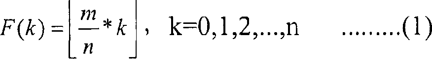
In equation (1) and (2),
Expression be less than or equal in the middle of the integer of set-point x maximum and
Expression is more than or equal to the minimum value in the middle of the integer of set-point x.
In equation (2), F (1) is defined as zero (0).That is to say F (1)=0.M position that is used for DCH and the method that is used for n the position of DSCH are defined by following equation (3) to utilize above-mentioned formula to arrange.The position that is used for DSCH is arranged in order into 1OL nL worthwhile value.
L=F(l-1)+G(l)+l.........(3)
In equation (3), (expression of 1≤l≤n) is used for central the 1st in n the position of DSCH to l.Therefore, equation (3) is used in and calculates and 1O the corresponding value in the 1st position that the position is central that is used for DSCH.
The m that is used for DCH position be arranged in 1OL is worthwhile to provide L value those values except equation (3).This is by following equation (4) definition.
F(l-2)+G(l-1)+l≤L≤F(l-1)+G(l)+l-1.........(4)
Following table 5 has shown for m: n=9: the F (k) and the G (k) of the various situations of 1,8: 2,7: 3,6: 4 and 5: 5.In table 5, the code symbols position of DSCH is at b
lOn have value (l-1).Under condition A1, the present invention before sending on the time slot two b
lThe position is mapped to two d
mThe position.Divided by 10 b
lRepeat the position 3 times of definition in table 5 on the position, and, after repeating, the last code symbols of the last code symbols of a TFCI encoder and the 2nd TFCI encoder is mapped to latter two b
30And b
31
Table 5
| m∶n | F(k) | F(1) | F(2) | F(3) | F(4) | F(5) |
| G(k) | G(1) | G(2) | G(3) | G(4) | G(5) | |
| The | ||||||
| 5∶5 | 1 | 2 | 3 | 4 | 5 | |
| 1 | 1 | 1 | 1 | 1 | ||
| 2 | 4 | 6 | 8 | 10 | ||
| 6∶4 | 1 | 3 | 4 | 6 | ||
| 1 | 1 | 1 | 1 | |||
| 2 | 4 | 7 | 9 | |||
| 7∶3 | 2 | 4 | 7 | |||
| 1 | 1 | 1 | ||||
| 2 | 5 | 8 | ||||
| 8∶2 | 4 | 8 | ||||
| 2 | 2 | |||||
| 3 | 8 | |||||
| 9∶1 | 9 | |||||
| 4 | ||||||
| 5 | ||||||
Fig. 6 is presented under the situation of condition A1, for m: n=6: 4, how will be used for 18 TFCI code symbols of DCH and be used for 12 TFCI code symbols of DSCH and figure that the 30-position TFCI field of DPCCH is complementary.As shown in table 5, for m: n=6: 4, the position of DSCH is 2,4,7 and 9 situation corresponding to the L value.That is to say, send d
1(b
1), d
3(b
3), d
6(b
6), d
8(b
8), d
11(b
11), d
13(b
13), d
16(b
16), d
18(b
18), d
21(b
21), d
23(b
23), d
26(b
26) and d
28(b
28).
Then, multiplexed TFCI code symbols is imposed on the multiplexer 420 of Fig. 4, in multiplexer 420, time division multiplexing is carried out in they and through-put power control (TPC) position, pilot bit and physical message.
Fig. 7 has shown the frame structure that sends to the DPCCH of UE from Node B, and wherein, top has shown the structure of time slot, and the middle part has shown the structure of radio frame and the structure that the bottom has shown the radio frame that sends in succession.As shown in Figure 7, with the time be divided into the basis multiplexed DPCCH and DPDCH are multiplexed into DPCH.For channelizing, expander 430 is the unit with the code element, the extended code of utilizing extended code generator 435 to provide, and the multiplexed code element of channel expansion, and be unit delivery channel spread signal with the chip.The scrambled code that scrambler 440 utilizes scrambled code generator 445 to provide, scrambling channel expansion signal.
A2. the structure of receiver and operation
Describe now and sending TFCI position that is used for DSCH and the process that is used for the TFCI position of DCH with specific ratios, the corresponding receiver of transmitter of encoding with variable coding rate.Receiver comprises the decoder of decoding with the receiving symbol of variable coding rate coding.
Fig. 8 has shown according to the structure embodiment of the invention and the corresponding receiver of transmitter as shown in Figure 4.With reference to Fig. 8, send to the scrambled code descrambling that the down link DPCH of UE utilizes scrambled code generator 845 to provide by descrambler 840 from Node B.Descrambling down link DPCH is the extended code despreading that unit utilizes extended code generator 835 to provide by despreader 830 with the code element.The DPCH code element of despreading becomes DPDCH, TPC position, pilot bit and TFCI code symbols by demultiplexer 820 demultiplexings.TFCI code symbols code element is used for the TFCI of DSCH and the information bit ratio of the TFCI that is used for DCH by demultiplexer 810 bases, demultiplexing becomes to depend on the coding TFCI code element that is used for DSCH and the coding TFCI code element that is used for DCH of code length control information once more, offers relevant decoder 800 and 805 then respectively.Depend on based on the code length control information of the TFCI position that is used for DSCH with the information bit ratio of the TFCI position that is used for DCH, decode the respectively coding TFCI code element that is used for DSCH and be used for the coding TFCI code element of DCH of decoder 800 and 805, then, export TFCI position that is used for DSCH and the TFCI position that is used for DCH respectively.
The structure and the operation of the decoder of several embodiment according to the present invention are described from now on.Decoder 800 shown in Figure 8 and 805 should be configured to decode with the variable coding rate coding, the TFCI code symbols that is used for DSCH and the TFCI code symbols that is used for DCH.
First embodiment (decoder)
Fig. 9 shown as shown in Figure 8 decoder 800 and 805 detailed structure.With reference to Fig. 9, receiving symbol r (t) is offered zero insertion device 900, simultaneously, code length information is offered controller 930.Controller 930 is determined punctured position according to code length information, and being used for determining that the control information of punctured position offers zero insertion device 900.The code length information representation is used in code length or the encoding rate in the encoder, and punctured position is represented in control information.Punctured position is represented the position for the code element that obtains to delete with the corresponding required code symbols length in position that receives from encoder.Table 6 has shown the punctured position that interrelates and store with code length.
Table 6
| Code length information (encoding rate) | Punctured position |
| (4,1) | F_28 |
| (7,2) | F_25 |
| (10,3) | F_22 |
| (13,4) | F_19 |
| (16,5) | F_16 |
| (19,6) | F_13 |
| (22,7) | F_10 |
| (25,8) | F_7 |
| (28,9) | F_4 |
In table 6, suppose that the code length information representation is used in the encoding rate in the encoder.(k, when n) expression was encoded into k code element to n input position, receiving symbol had code length k when encoding rate.And the F_n of table 6 represents n punctured bit.Can determine that from table 6 control information (punctured position) makes zero insertion device 900 can irrespectively keep the number (32) of output symbol with the code length of receiving symbol.
With reference to table 6, controller 930 is for encoding rate (4,1) output and 28 information that punctured position is relevant, for encoding rate (7,2) output and 25 information that punctured position is relevant, for encoding rate (10,3) output and 22 information that punctured position is relevant, for encoding rate (13,4) output and 19 information that punctured position is relevant, for encoding rate (19,6) output and 13 information that punctured position is relevant, for encoding rate (22,7) output and 10 information that punctured position is relevant, for encoding rate (25,8) output and 7 information that punctured position is relevant, with for encoding rate (28,9) output and 4 information that punctured position is relevant.For various situations, punctured position is identical with the punctured position that provides in the description of encoder.
Zero insertion device 900 is according to control information, and in the punctured position of 0 insertion receiving symbol, then, output length is 32 code element stream.Code element stream is offered quick Hadamard inverse converter (IFHT) 920 and multiplier 902,904 and 906.The code element stream that offers multiplier 902,904 and 906 multiplies each other with mask function M1, M2 and the M15 that mask generator 910 provides respectively.The output symbol of multiplier 902,904 and 906 is offered switch 952,954 and 956 respectively.This moment, controller 930 use/does not use expression the switching control information of mask function to offer switch 952,954 and 956 according to code length information.For example, owing to (4,1), (7,2), (10,3), (13,4) and (19,6) encoder do not use the mask function, according to switching control information, switch 952,954 and 956 all disconnects.But, owing to during the basic code word of one of (22,7) and (23,7) encoder use, have only switch 952 to connect.Like this, controller 930 is controlled switch 952,954 and 956 according to the number of the mask function that uses according to encoding rate.Then, IFHT 922,924 and 926 carries out quick Hadamard inverse transformation to 32 code elements that receive from zero insertion device 900 respectively, and, calculate code element and can be used in correlation between all walsh codes in the transmitter.And IFHT determines the highest correlation in the middle of the correlation and has the index of the walsh code of high correlation.Therefore, IFHT 920,922,924 and 926 is respectively the index of the mask function that multiply by received signal, the highest correlation with have that the index of the walsh code of high correlation offers correlation comparator 940.Do not taken advantage of by any mask function owing to offer the signal of IFHT 920, therefore, the identifier of mask function becomes ' 0 '.Correlation comparator 940 is determined the highest correlation by the correlation that IFHT relatively provides, and the index of the mask index of high correlation and the index of walsh code are combined having.
Second embodiment (decoder)
Describe below according to being used in the decoder that adjustable length code-adaptive ground in the encoder carries out decode operation.
At first, decoder is risen make required IFHT of time spent with the corresponding decoder of adjustable length walsh codes device and described.When decoder and (7,2) encoder link together when operating, use with length be 4 (2
2) the relevant IFHT of walsh codes device.When decoder and (10,3) encoder link together when operating, use with length be 8 (2
3) the relevant IFHT of walsh codes device.When decoder and (13,4) encoder link together when operating, use with length be 16 (2
4) the relevant IFHT of walsh codes device.When decoder and (16,5) encoder link together when operating, use with length be 32 (2
5) the relevant IFHT of walsh codes device.In addition, when decoder and (19,6), (22,7), (25,8), when (28,9) and (32,10) encoder links together and operates, use and length is 32 (2
5) the relevant IFHT of walsh codes device.In order to operate in decoder, IFHT should be able to operate variable-length.The invention provides the structure of the IFHT that can operate variable-length.
Figure 11 has shown first and second decoders 800 shown in Figure 8 and 805 structure.With reference to Figure 11, the code symbols r (t) that receives from encoder is offered zero insertion device 1100, simultaneously, the information of the code length that relevant encoder is used when encoding receiving symbol offers controller 1130.The information that controller 1130 and the code length that is suitable for encoder are stored relevant punctured position with interrelating, and offer zero insertion device 1100 with the control information that is stored in wherein that interrelates of code length information.With code length interrelate the storage punctured position be presented in the table 6.
With reference to table 6, controller 1130 is for encoding rate (4,1) output and 28 information that punctured position is relevant, for encoding rate (7,2) output and 25 information that punctured position is relevant, for encoding rate (10,3) output and 22 information that punctured position is relevant, for encoding rate (13,4) output and 19 information that punctured position is relevant, for encoding rate (19,6) output and 13 information that punctured position is relevant, for encoding rate (22,7) output and 10 information that punctured position is relevant, for encoding rate (25,8) output and 7 information that punctured position is relevant, with for encoding rate (28,9) output and 4 information that punctured position is relevant.For various situations, punctured position is identical with the punctured position that provides in the description of encoder.
Zero insertion device 1100 is according to the control information that comes self-controller 1130, and in the punctured position of 0 insertion receiving symbol, then, output length is 32 code element stream.Code element stream is offered quick Hadamard inverse converter (IFHT) 1120 and multiplier 1102,1104 and 1106.The signal that offers multiplier 1102,1104 and 1106 multiplies each other with mask function M1, M2 and the M15 that mask generator 910 provides respectively.The mask function that mask generator 1110 generates is identical with the mask function in being used in encoder.The output symbol of multiplier 1102,1104 and 1106 is offered switch 1152,1154 and 1156 respectively.This moment, controller 1130 use/does not use expression the switching control information of mask function to offer switch 1152,1154 and 1156 according to the code length information that receives.Consequently, switch 1152,1154 and 1156 allows the output symbol of multiplier 1102,1104 and 1106 pass through respectively.For example, the mask function is not with encoding rate (4,1), (7,2), (10,3), (13,4) and (19,6) use, according to switching control information, switch 1152,1154 and 1156 all disconnects, thereby, block the output symbol of multiplier 1102,1104 and 1106.Owing to have only a mask code element to use, therefore,, have only switch 1152 to connect, and remaining switch 1104 and 1106 disconnect according to switching control information with encoding rate (22,7).Like this, the number of the mask function among determining to use according to encoding rate and depend on the number of the mask function among using, the control switch.Therefore, when first and second decoders 800 shown in Figure 8 and 805 are used as (4,1), (7,2), (10,3), (13,4), (16,5) and (19,6) decoder, only enable IFHT1120.When the number of input information position less than 18 the time, first and second decoders 800 and 805 are as (4,1), (7,2), (10,3), (13,4), (16,5) and (19,6) decoder.Therefore, IFHT 11 should be adaptively to several code lengths, and promptly several encoding rates are operated.Controller 1130 generates the control information of the code length of the relevant walsh codes device of expression, and control information is offered IFHT 1120.Then, IFHT 1120,1124 and 1126 carries out quick Hadamard inverse transformation to 32 code elements that receive from zero insertion device 1100 respectively, and calculates code element and have correlation between the walsh code of length-specific.IFHT 1120 is the highest correlation in the middle of the index of mask function, correlation and have that the index of the walsh code of high correlation offers correlation comparator 1140.IFHT 1120 offers correlation comparator 1140 to ' 0 ', as the index of mask function.Provide ' 0 ' index to mean that input symbols is not taken advantage of by the mask function as the mask function.
In case receive code element by relevant switch 1152,1154 and 1156, other IFHT 1122,1124 and 1126 just carries out quick Hadamard inverse transformation respectively.And calculate through the correlation between the walsh code of quick Hadamard inverse transformation.After having calculated correlation, IFHT 1122,1124 and 1126 each all the highest correlation in the middle of the index of employed mask function, the correlation with have that the index of the walsh code of high correlation offers correlation comparator 1140.Then, correlation comparator 1140 is the correlation that provides of IFHT relatively, and the mask index and the walsh code index of high correlation are combined having.
Figure 12 has shown the operation of carrying out based in conjunction with Figure 10 IFHT 1120 described quick Hadamard inversion process, shown in Figure 11.Specifically, Figure 12 has shown in order to allow decoder 800 and 805 as (4,1), (7,2), (10,3), (13,4), (16,5) and (19,6) decoder, the overall plan that IFHT 1120 operates.
B. only improve the method for the encoding rate of a TFCI
With regard to minimum range, preferably repeat (3,2) single worker's sign indicating number 3 times, then, shrink last code symbols, so that obtain (8,2) code, a kind of optimum code with one of required encoding rate of the encoding rate that only improves a TFCI.Table 7 has shown the input information position of (3,2) single worker's sign indicating number and according to the relation between (3,2) single worker's code word of input information position output.
Table 7
| The input information position | (3,2) single worker's code word |
| 00 | 000 |
| 01 | 101 |
| 10 | 011 |
| 11 | 110 |
Table 8 has shown input information position and the single worker's sign indicating number of repetition (3,2) 3 times, then, shrinks the relation between (8,2) single worker's code word that last code symbols obtains.
Table 8
| The input information position | (8,2) single worker's code word |
| 00 | 000?000?00 |
| 01 | 101?101?10 |
| 10 | 011?011?01 |
| 11 | 110?110?11 |
But, repeat (3,2) single worker's code word 3 times, then, (8,2) single worker's code word of shrinking last code symbols acquisition can realize by shortening existing (16,4) Reed-Muller sign indicating number.
The example of method for reducing is described below.(16,4) Reed-Muller sign indicating number is that length is the linear combination of 4 basic code words of 16, and herein, ' 4 ' is the number of input information position.Receive only 2 positions in the middle of 16 input information positions and be equivalent to that only to use length be the linear combination of 2 basic code words in the middle of 4 basic code words of 16, and do not use remaining code word.In addition,, then, shrink 8 central code elements of 16 code elements, just can utilize (16,4) encoder to realize (8,2) encoder by limiting the use of basic code word.Table 9 has shown method for reducing.
Table 9
| The input information position | Code word | |||||||||||||||
| 0000 | 0( *) | 0 | 0 | 0 | 0( *) | 0 | 0 | 0 | 0( *) | 0 | 0 | 0( *) | 0( *) | 0( *) | 0( *) | 0( *) |
| 0001 | 0( *) | 1 | 0 | 1 | 0( *) | 1 | 0 | 1 | 0( *) | 1 | 0 | 1( *) | 0( *) | 1( *) | 0( *) | 1( *) |
| 0010 | 0( *) | 0 | 1 | 1 | 0( *) | 0 | 1 | 1 | 0( *) | 0 | 1 | 1( *) | 0( *) | 0( *) | 1( *) | 1( *) |
| 0011 | 0( *) | 1 | 1 | 0 | 0( *) | 1 | 1 | 0 | 0( *) | 1 | 1 | 0( *) | 0( *) | 1( *) | 1( *) | 0( *) |
| 0100 | 0 | 0 | 0 | 0 | 1 | 1 | 1 | 1 | 0 | 0 | 0 | 0 | 1 | 1 | 1 | 1 |
| 0101 | 0 | 1 | 0 | 1 | 1 | 0 | 1 | 0 | 0 | 1 | 0 | 1 | 1 | 0 | 1 | 0 |
| 0110 | 0 | 0 | 1 | 1 | 1 | 1 | 0 | 0 | 0 | 0 | 1 | 1 | 1 | 1 | 0 | 0 |
| 0111 | 0 | 1 | 1 | 0 | 1 | 0 | 0 | 1 | 0 | 1 | 1 | 0 | 1 | 0 | 0 | 1 |
| 1000 | 0 | 0 | 0 | 0 | 0 | 0 | 0 | 0 | 1 | 1 | 1 | 1 | 1 | 1 | 1 | 1 |
| 1001 | 0 | 1 | 0 | 1 | 0 | 1 | 0 | 1 | 1 | 0 | 1 | 0 | 1 | 0 | 1 | 0 |
| 1010 | 0 | 0 | 1 | 1 | 0 | 0 | 1 | 1 | 1 | 1 | 0 | 0 | 1 | 1 | 0 | 0 |
| 1011 | 0 | 1 | 1 | 0 | 0 | 1 | 1 | 0 | 1 | 0 | 0 | 1 | 1 | 0 | 0 | 1 |
| 1100 | 0 | 0 | 0 | 0 | 1 | 1 | 1 | 1 | 1 | 1 | 1 | 1 | 0 | 0 | 0 | 0 |
| 1101 | 0 | 1 | 0 | 1 | 1 | 0 | 1 | 0 | 1 | 0 | 1 | 0 | 0 | 1 | 0 | 1 |
| 1110 | 0 | 0 | 1 | 1 | 1 | 1 | 0 | 0 | 1 | 1 | 0 | 0 | 0 | 0 | 1 | 1 |
| 1111 | 0 | 1 | 1 | 0 | 1 | 0 | 0 | 1 | 1 | 0 | 0 | 1 | 0 | 1 | 1 | 0 |
With reference to table 9, each (16,4) code word all is that length is the linear combination of 4 thick line base code words of 16.In order to obtain (8,2) code, 4 top 2 basic code words that basic code word is central have only been used.Then, 12 code words just are out of use automatically below remaining.Therefore, top 4 code words have only been used.In addition,, generate length and be 8 basic code word, be necessary to shrink 8 code elements in order to be in the middle of 4 code words of 16 from length.By shrink by in the table 4 (
*) code element of expression, then, remaining 8 code symbols is concentrated together, can obtain the single worker's code word in (8,2) shown in the table 3.
Here, to describe by shortening (32 of second order Reed-Muller sign indicating number, 10) subcode, generation be used for 1: 9 the information bit ratio { (3,1) optimum code and (29,9) optimum code }, { (4,1) optimum code and (28,9) optimum code }, { (5,1) optimum code and (27,9) optimum code } the structure of encoder, generation be used for 2: 8 the information bit ratio { (6,2) optimum code and (26,8) optimum code }, { (7,2) optimum code and (25,8) optimum code }, { (8,2) optimum code and (24,8) optimum code } the structure of encoder, generation is used for { (9,3) optimum code and (23,7) optimum code } of 3: 7 information letter ratio, { (10,3) optimum code and (22,7) optimum code }, the structure of the encoder of { (11,3) optimum code and (21,7) optimum code }, generation be used for 4: 6 the information bit ratio { (12,4) optimum code and (20,6) optimum code }, { (13,4) optimum code and (19,6) optimum code }, { (14,4) optimum code and (18,6) optimum code } the structure of encoder, generation is used for the structure of encoder of { (16,5) optimum code and (32,10) optimum code } of 5: 5 information letter ratio.In addition, structure with the corresponding decoder of encoder also will be described below.
B1. the structure of transmitter and operation
Embodiments of the invention provide as the ratio in the input information position be under 5: 5 the logical division pattern do, cutting apart firmly under the pattern, before coding, divide the equipment and the method for 10 information bits by the ratio of 1: 9,2: 8,3: 7,4: 6,5: 5,6: 4,7: 3,8: 2 and 9: 1.In addition, here also hypothesis send the encoding rate of a TFCI of the TFCI be used for DSCH and the encoding rate that sends the 2nd TFCI of the TFCI that is used for DCH had all improved before sending.That is to say,, so, use (3,1) code and (29,9) code if the ratio of DCH information bit and DSCH information bit is 1: 9.If the DCH information bit is 2: 8 with the ratio of DSCH information bit, so, use (6,2) code and (26,8) code.If the DCH information bit is 3: 7 with the ratio of DSCH information bit, so, use (9,3) code and (23,7) code.If the DCH information bit is 4: 6 with the ratio of DSCH information bit, so, use (12,4) code and (20,6) code.If the DCH information bit is 6: 4 with the ratio of DSCH information bit, so, use (18,6) code and (14,4) code.If the DCH information bit is 7: 3 with the ratio of DSCH information bit, so, use (21,7) code and (11,3) code.If the DCH information bit is 8: 2 with the ratio of DSCH information bit, so, use (26,8) code and (6,2) code.If the DCH information bit is 9: 1 with the ratio of DSCH information bit, so, use (27,9) code and (5,1) code.
Fig. 4 has shown the structure according to the transmitter of the embodiment of the invention.With reference to Fig. 4, offering first and second encoders 400 and 405 respectively than TFCI position of dividing that is used for DSCH and the TFCI position that is used for DCH according to information bit.Here, the TFCI position that is called as a TFCI (field 1) or a TFCI position and is used for DCH, the TFCI position that is used for DSCH is called as TFCI (field 2) or the 2nd TFCI position.The TFCI position that is used for DSCH is generated by a TFCI position generator 450, and the TFCI position relevant with being used for DCH generated by the 2nd TFCI position generator 455.The first and second TFCI positions have different as mentioned above speed according to their information bit ratio.In addition, promptly relevant the control signal of indication code long letter breath according to the information of information bit than the length value of the code word that is provided with, offer first and second encoders 400 and 405.Code length information is generated by code length information generator 460, and has the value that the length with a TFCI position and the 2nd TFCI position changes.
When the information bit ratio is 6: 4, encoder 400 responses make 400 (20 of encoders, 6) control signal of encoder effect, reception is used for 6-position TFCI and 20 code symbols of output of DSCH, and encoder 405 responses make 405 of encoders (12,4) control signal of encoder effect receives 4-position TFCI and 12 code symbols of output of being used for DCH.When the information bit ratio is 7: 3, encoder 400 responses make 400 (23 of encoders, 7) control signal of encoder effect, reception is used for 7-position TFCI and 23 code symbols of output of DSCH, and encoder 405 responses make 405 of encoders (9,3) control signal of encoder effect receives 3-position TFCI and 9 code symbols of output of being used for DCH.When the information bit ratio is 8: 2, encoder 400 responses make 400 (26 of encoders, 8) control signal of encoder effect, reception is used for 8-position TFCI and 26 code symbols of output of DSCH, and encoder 405 responses make 405 of encoders (6,2) control signal of encoder effect receives 2-position TFCI and 6 code symbols of output of being used for DCH.When the information bit ratio is 9: 1, encoder 400 responses make 400 (29 of encoders, 9) control signal of encoder effect, reception is used for 9-position TFCI and 29 code symbols of output of DSCH, and encoder 405 responses make 405 of encoders (3,1) control signal of encoder effect receives 1-position TFCI and 3 code symbols of output of being used for DCH.
Fig. 5 has shown the detailed structure of encoder 400 and 405.In Fig. 4, for a TFCI and the 2nd TFCI provide the separated coding device.But when life period postponed between generation the one TFCI code word and the 2nd TFCI code word, generating the first and second TFCI code words can realize with single encoded device.Below with reference to of the operation of Fig. 5 detailed description according to the encoder of the embodiment of the invention.
1) TFCI is 1: 9 with the information bit ratio of the 2nd TFCI
For 1: 9 information bit ratio, encoder 400 was as (3,1) encoder, and encoder 405 is as (29,9) encoder.Below with reference to the operation of Fig. 5 (3,1) described separately encoder and (29,9) encoder,
The operation of (3,1) encoder at first, is described with reference to Fig. 5.With reference to Fig. 5, an input position a0 is normally offered encoder, and remaining input position a1, a2, a3, a4, a5, a6, a7, a8 and a9 use ' 0 ' to fill.A0 is applied on the multiplier 510 the input position, a1 is applied on the multiplier 512 the input position, a2 is applied on the multiplier 514 the input position, a3 is applied on the multiplier 516 the input position, and a4 is applied on the multiplier 518 the input position, and a5 is applied on the multiplier 520 the input position, a6 is applied on the multiplier 522 the input position, a7 is applied on the multiplier 524 the input position, input position a8 is applied on the multiplier 526 and input position a9 be applied on the multiplier 528.Simultaneously, Wolsh code generator 500 generates basic code word W 1=10101010101010110101010101010100, and the basic code word W 1 that generates is offered multiplier 510.Then, multiplier 510 is that unit will import a position a0 and multiply by basic code word W 1 with the code element, and its output is offered XOR (XOR) arithmetic unit 540.And Wolsh code generator 500 generates other basic code word W 2, W4, W8 and W16, and they are offered multiplier 512,514,516 and 518 respectively.Complete 1 code generator 502 generates complete 1 basic code word (or complete 1 sequence), and the complete 1 basic code word that generates is offered multiplier 520.Mask generator 504 generates basic code word M1, M2, M4 and M8, and basic code word M1, the M2, M4 and the M8 that generate are offered multiplier 522,524,526 and 528 respectively.But, because imposing on input position a1, a2, a3, a4, a5, a6, a7, a8 and the a9 of multiplier 512,514,516,518,520,522,524,526 and 528 all is 0, multiplier 512,514,516,518,520,522,524,526 and 528 outputs to exclusive-OR operator 540 to 0, does not therefore influence the output of exclusive-OR operator 540.That is to say, carry out the output valve that the definite value of XOR equals multiplier 510 by the output valve of 540 pairs of multipliers of exclusive-OR operator 510,512,514,516,518,520,522,524,526 and 528.32 code elements from exclusive-OR operator 540 outputs are offered constrictor 560.This moment, controller 550 receiving code long letters breath, and, the control signal of indication punctured position is offered constrictor 560 according to code length information.Then, constrictor 560 is according to the control signal of slave controller 550 outputs, in the middle of 32 code symbols altogether of forming by the 0th to the 31st code element, shrink the 1st, 3,5,6,7,8,9,10,11,12,13,14,15,16,17,18,19,20,21,22,23,24,25,26,27,28,29,30 and 31 code symbols.In other words, constrictor 560 shrinks 29 code elements in the middle of 32 code symbols, therefore, exports 3 not puncturing code symbols.
The operation of (29,9) encoder then, is described with reference to Fig. 5.With reference to Fig. 5, nine input position a0, a1, a2, a3, a4, a5, a6, a7 and a8 are normally offered encoder, and remaining input position a9 fills with ' 0 '.A0 is applied on the multiplier 510 the input position, a1 is applied on the multiplier 512 the input position, a2 is applied on the multiplier 514 the input position, a3 is applied on the multiplier 516 the input position, and a4 is applied on the multiplier 518 the input position, and a5 is applied on the multiplier 520 the input position, a6 is applied on the multiplier 522 the input position, a7 is applied on the multiplier 524 the input position, input position a8 is applied on the multiplier 526 and input position a9 be applied on the multiplier 528.Simultaneously, Wolsh code generator 500 offers multiplier 510 to basic code word W 1=1,010,101,010,101,011,010,101,010,101 0100, basic code word W 2=01100110011001101100110011001100 is offered multiplier 512, basic code word W 4=00011110000111100011110000111100 is offered multiplier 514, basic code word W 8=00000001111111100000001111111100 is offered multiplier 516 and basic code word W 1 6=00000000000000011111111111111101 is offered multiplier 518.Then, multiplier 510 is that unit multiply by an input position a0 with basic code word W 1 with the code element, and its output is offered exclusive-OR operator 540.Multiplier 512 is that unit multiply by an input position a1 with basic code word W 2 with the code element, and its output is offered exclusive-OR operator 540.Multiplier 514 is that unit multiply by an input position a2 with basic code word W 4 with the code element, and its output is offered exclusive-OR operator 540.Multiplier 516 is that unit multiply by an input position a3 with basic code word W 8 with the code element, and its output is offered exclusive-OR operator 540.Multiplier 518 is that unit multiply by an input position a4 with basic code word W 16 with the code element, and its output is offered exclusive-OR operator 540.In addition, complete 1 code generator, 502 generation length are 32 complete 1 basic code word, and complete 1 a basic code word that generates is offered multiplier 520.Then, multiplier 520 is that unit multiply by an input position a5 with complete 1 basic code word with the code element, and its output is offered exclusive-OR operator 540.Mask generator 504 offers multiplier 522 to basic code word M1=0101 0,000 1,100 0,111 1,100 00,011,101 1101, basic code word M2=0000 0,011 1,001 1,011 1,011 01,110,001 1100 is offered multiplier 524 and basic code word M4=0001 0,101 1,111 0,010 0,110 11,001,010 1100 is offered multiplier 526.Then, multiplier 522 is that unit multiply by an input position a6 with basic code word M1 with the code element, and its output is offered exclusive-OR operator 540.Multiplier 524 is that unit multiply by an input position a7 with basic code word M2 with the code element, and its output is offered exclusive-OR operator 540.Multiplier 526 is that unit multiply by an input position a8 with basic code word M4 with the code element, and its output is offered exclusive-OR operator 540.And mask generator 504 generates basic code word M8, and the basic code word M8 that generates is offered multiplier 528.But, be 0 owing to impose on the input position a9 of multiplier 528, multiplier 528 outputs to exclusive-OR operator 540 to 0, therefore, does not influence the output of exclusive-OR operator 540.That is to say, carry out the definite value of XOR by the output valve of 540 pairs of multipliers of exclusive-OR operator 512,514,516,518,520,522,524,526 and 528 and equal the output valve of multiplier 510,512,514,516,518,520,522,524 and 526 is carried out the value that XOR is determined.32 code elements from exclusive-OR operator 540 outputs are offered constrictor 560.This moment, controller 550 receiving code long letters breath, and, according to code length information, the control signal of indication punctured position is offered constrictor 560.Then, constrictor 560 is according to the control signal of slave controller 550 output, and in the middle of 32 code symbols altogether of being made up of the 0th to the 31st code element, the 6th, 10 and 11 code symbols are fallen in contraction.In other words, constrictor 560 shrinks 3 code elements in the middle of 32 code symbols, therefore, exports 29 not puncturing code symbols.
2) TFCI is 2: 8 with the information bit ratio of the 2nd TFCI
For 2: 8 information bit ratio, encoder 400 was as (6,2) encoder, and encoder 405 is as (26,8) encoder.Operation below with reference to Fig. 5 (6,2) described separately encoder and (26,8) encoder.
The operation of (6: 2) encoder at first, is described with reference to Fig. 5.With reference to Fig. 5, two input position a0 and a1 are normally offered encoder 400, and remaining input position a2, a3, a4, a5, a6, a7, a8 and a9 use ' 0 ' to fill.A0 is applied on the multiplier 510 the input position, a1 is applied on the multiplier 512 the input position, a2 is applied on the multiplier 514 the input position, a3 is applied on the multiplier 516 the input position, and a4 is applied on the multiplier 518 the input position, and a5 is applied on the multiplier 520 the input position, a6 is applied on the multiplier 522 the input position, a7 is applied on the multiplier 524 the input position, input position a8 is applied on the multiplier 526 and input position a9 be applied on the multiplier 528.Simultaneously, Wolsh code generator 500 offers basic code word W 1=10101010101010110101010101010100 multiplier 510 and basic code word W 2,=01,100,110 011001101100110011001100 is offered multiplier 512.Multiplier 510 is that unit multiply by an input position a0 with basic code word W 1 with the code element, and its output is offered XOR (XOR) arithmetic unit 540.Multiplier 512 is that unit multiply by an input position a1 with basic code word W 2 with the code element, and its output is offered XOR (XOR) arithmetic unit 540.And Wolsh code generator 500 generates other basic code word W 4, W8 and W16, and they are offered multiplier 514,516 and 518 respectively.Complete 1 code generator 502 generates complete 1 basic code word, and the complete 1 basic code word that generates is offered multiplier 520.Mask generator 504 generates basic code word M1, M2, M4 and M8, and basic code word M1, the M2, M4 and the M8 that generate are offered multiplier 522,524,526 and 528 respectively.But, because imposing on input position a2, a3, a4, a5, a6, a7, a8 and the a9 of multiplier 514,516,518,520,522,524,526 and 528 all is 0, multiplier 514,516,518,520,522,524,526 and 528 outputs to exclusive-OR operator 540 to 0, does not therefore influence the output of exclusive-OR operator 540.That is to say, carry out the definite value of XOR by the output valve of 540 pairs of multipliers of exclusive-OR operator 510,512,514,516,518,520,522,524,526 and 528 and equal the output valve of multiplier 510 and 512 is carried out the value that XOR is determined.32 code elements from exclusive-OR operator 540 outputs are offered constrictor 560.This moment, controller 550 receiving code long letters breath, and, according to code length information, the control signal of indication punctured position is offered constrictor 560.Then, constrictor 560 is according to the control signal of slave controller 550 outputs, in the middle of 32 code symbols altogether of forming by the 0th to the 31st code element, shrink the 3rd, 7,8,9,10,11,12,13,14,15,16,17,18,19,20,21,22,23,24,25,26,27,28,29,30 and 31 code symbols.In other words, constrictor 560 shrinks 26 code elements in the middle of 32 code symbols, therefore, exports 6 not puncturing code symbols.
The operation of (26,8) encoder then, is described with reference to Fig. 5.With reference to Fig. 5, eight input position a0, a1, a2, a3, a4, a5, a6 and a7 are normally offered encoder, and remaining input position a8 and a9 use ' 0 ' to fill.A0 is applied on the multiplier 510 the input position, a1 is applied on the multiplier 512 the input position, a2 is applied on the multiplier 514 the input position, a3 is applied on the multiplier 516 the input position, and a4 is applied on the multiplier 518 the input position, and a5 is applied on the multiplier 520 the input position, a6 is applied on the multiplier 522 the input position, a7 is applied on the multiplier 524 the input position, input position a8 is applied on the multiplier 526 and input position a9 be applied on the multiplier 528.Simultaneously, Wolsh code generator 500 offers multiplier 510 to basic code word W 1,=10,101,010,101,010,110,101 010101010100, basic code word W 2=,011,001,100,110,011,011,001,100 11001100 is offered multiplier 512, basic code word W 4=0,001,111,000,011,110,001,111,000,011 1100 is offered multiplier 514, basic code word W 8=00000001111111100000001111111100 is offered multiplier 516 and basic code word W 16=00000000000000011111111111111101 is offered multiplier 518.Then, multiplier 510 is that unit multiply by an input position a0 with basic code word W 1 with the code element, and its output is offered exclusive-OR operator 540.Multiplier 512 is that unit multiply by an input position a1 with basic code word W 2 with the code element, and its output is offered exclusive-OR operator 540.Multiplier 514 is that unit multiply by an input position a2 with basic code word W 4 with the code element, and its output is offered exclusive-OR operator 540.Multiplier 516 is that unit multiply by an input position a3 with basic code word W 8 with the code element, and its output is offered exclusive-OR operator 540.Multiplier 518 is that unit multiply by an input position a4 with basic code word W 16 with the code element, and its output is offered exclusive-OR operator 540.In addition, complete 1 code generator, 502 generation length are 32 complete 1 basic code word, and complete 1 a basic code word that generates is offered multiplier 520.Then, multiplier 520 is that unit multiply by an input position a5 with complete 1 basic code word with the code element, and its output is offered exclusive-OR operator 540.And mask generator 504 offers basic code word M1=0101 0,000 1,100 0,111 11,000,001 1,101 1101 multiplier 522 and basic code word M2=0000 0,011 1,001 1,011 10,110,111 0,001 1100 is offered multiplier 524.Then, multiplier 522 is that unit multiply by an input position a6 with basic code word M1 with the code element, and its output is offered exclusive-OR operator 540.Multiplier 524 is that unit multiply by an input position a7 with basic code word M2 with the code element, and its output is offered exclusive-OR operator 540.And mask generator 504 generates basic code word M4 and M8, and the basic code word M4 and the M8 that generate are offered multiplier 526 and 528 respectively.But because the input position a8 and the a9 that impose on multiplier 526 and 528 are 0, multiplier 526 and 528 outputs to exclusive-OR operator 540 to 0, therefore, does not influence the output of exclusive-OR operator 540.That is to say, carry out the definite value of XOR by the output valve of 540 pairs of multipliers of exclusive-OR operator 510,512,514,516,518,520,522,524,526 and 528 and equal the output valve of multiplier 510,512,514,516,518,520,522 and 524 is carried out the value that XOR is determined.32 code elements from exclusive-OR operator 540 outputs are offered constrictor 560.This moment, controller 550 receiving code long letters breath, and, the control signal of indication punctured position is offered constrictor 560 according to code length information.Then, constrictor 560 is according to the control signal of slave controller 550 output, and in the middle of 32 code symbols altogether of being made up of the 0th to the 31st code element, the 7th, 13,15,20,25 and 30 code symbols are fallen in contraction.In other words, constrictor 560 shrinks 6 code elements in the middle of 32 code symbols, therefore, exports 26 not puncturing code symbols.
3) TFCI is 3: 7 with the information bit ratio of the 2nd TFCI
For 3: 7 information bit ratio, encoder 400 was as (9,3) encoder, and encoder 405 is as (23,7) encoder.Operation below with reference to Fig. 5 (9,3) described separately encoder and (23,7) encoder.
The operation of (9,3) encoder at first, is described with reference to Fig. 5.With reference to Fig. 5, three input position a0, a1 and a2 are normally offered encoder, and remaining input position a3, a4, a5, a6, a7, a8 and a9 use ' 0 ' to fill.A0 is applied on the multiplier 510 the input position, a1 is applied on the multiplier 512 the input position, a2 is applied on the multiplier 514 the input position, a3 is applied on the multiplier 516 the input position, and a4 is applied on the multiplier 518 the input position, and a5 is applied on the multiplier 520 the input position, a6 is applied on the multiplier 522 the input position, a7 is applied on the multiplier 524 the input position, input position a8 is applied on the multiplier 526 and input position a9 be applied on the multiplier 528.Simultaneously, Wolsh code generator 500 offers multiplier 510 to basic code word W 1,=10,101,010,101,010,110,101 010101010100, basic code word W 2=,011,001,100,110,011,011,001,100 11001100 is offered multiplier 512 and basic code word W 4,=00,011,110 0,001,111,000,111,100 00111100 is offered multiplier 514.Multiplier 510 is that unit multiply by an input position a0 with basic code word W 1 with the code element, and its output is offered XOR (XOR) arithmetic unit 540.Multiplier 512 is that unit multiply by an input position a1 with basic code word W 2 with the code element, and its output is offered XOR (XOR) arithmetic unit 540.Multiplier 514 is that unit multiply by an input position a2 with basic code word W 4 with the code element, and its output is offered XOR (XOR) arithmetic unit 540.And Wolsh code generator 500 generates other basic code word W 8 and W16, and they are offered multiplier 516 and 518 respectively.Complete 1 code generator 502 generates complete 1 basic code word, and the complete 1 basic code word that generates is offered multiplier 520.Mask generator 504 generates basic code word M1, M2, M4 and M8, and basic code word M1, the M2, M4 and the M8 that generate are offered multiplier 522,524,526 and 528 respectively.But, because imposing on input position a3, a4, a5, a6, a7, a8 and the a9 of multiplier 516,518,520,522,524,526 and 528 all is 0, multiplier 516,518,520,522,524,526 and 528 outputs to exclusive-OR operator 540 to 0, does not therefore influence the output of exclusive-OR operator 540.That is to say, carry out the definite value of XOR by the output valve of 540 pairs of multipliers of exclusive-OR operator 510,512,514,516,518,520,522,524,526 and 528 and equal the output valve of multiplier 510,512 and 514 is carried out the value that XOR is determined.32 code elements from exclusive-OR operator 540 outputs are offered constrictor 560.This moment, controller 550 receiving code long letters breath, and, the control signal of indication punctured position is offered constrictor 560 according to code length information.Then, constrictor 560 is according to the control signal of slave controller 550 outputs, in the middle of 32 code symbols altogether of forming by the 0th to the 31st code element, shrink the 7th, 8,11,12,13,14,15,16,17,18,19,20,21,22,23,24,25,26,27,28,29,30 and 31 code symbols.In other words, constrictor 560 shrinks 23 code elements in the middle of 32 code symbols, therefore, exports 9 not puncturing code symbols.
Then, with reference to the operation that Fig. 5 describes (23,7) encoder, with reference to Fig. 5, seven input position a0, a1, a2, a3, a4, a5 and a6 are normally offered encoder, and remaining input position a7, a8 and a9 use ' 0 ' to fill.A0 is applied on the multiplier 510 the input position, a1 is applied on the multiplier 512 the input position, a2 is applied on the multiplier 514 the input position, a3 is applied on the multiplier 516 the input position, and a4 is applied on the multiplier 518 the input position, and a5 is applied on the multiplier 520 the input position, a6 is applied on the multiplier 522 the input position, a7 is applied on the multiplier 524 the input position, input position a8 is applied on the multiplier 526 and input position a9 be applied on the multiplier 528.Simultaneously, Wolsh code generator 500 offers multiplier 510 to basic code word W 1=10101010101010110101010101010100, basic code word W 2=01100110011001101100110011001100 is offered multiplier 512, basic code word W 4=00011110000111100011110000111100 is offered multiplier 514, basic code word W 8=00000001111111100000001111111100 is offered multiplier 516 and basic code word W 1,6=0,000 0000000000011111111111111101 is offered multiplier 518.Then, multiplier 510 is that unit multiply by an input position a0 with basic code word W 1 with the code element, and its output is offered exclusive-OR operator 540.Multiplier 512 is that unit multiply by an input position a1 with basic code word W 2 with the code element, and its output is offered exclusive-OR operator 540.Multiplier 514 is that unit multiply by an input position a2 with basic code word W 4 with the code element, and its output is offered exclusive-OR operator 540.Multiplier 516 is that unit multiply by an input position a3 with basic code word W 8 with the code element, and its output is offered exclusive-OR operator 540.Multiplier 518 is that unit multiply by an input position a4 with basic code word W 16 with the code element, and its output is offered exclusive-OR operator 540.In addition, complete 1 code generator, 502 generation length are 32 complete 1 basic code word, and complete 1 a basic code word that generates is offered multiplier 520.Then, multiplier 520 is that unit multiply by an input position a5 with complete 1 basic code word with the code element, and its output is offered exclusive-OR operator 540.And mask generator 504 offers multiplier 522 to basic code word M1=0101 00,001,100 0,111 1,100 0,001 1,101 1101.Then, multiplier 522 is that unit multiply by an input position a6 with basic code word M1 with the code element, and its output is offered exclusive-OR operator 540.And mask generator 504 generates basic code word M2, M4 and M8, and basic code word M2, the M4 and the M8 that generate are offered multiplier 524,526 and 528 respectively.But because input position a7, the a8 and the a9 that impose on multiplier 524,526 and 528 are 0, multiplier 524,526 and 528 outputs to exclusive-OR operator 540 to 0, therefore, does not influence the output of exclusive-OR operator 540.That is to say, carry out the definite value of XOR by the output valve of 540 pairs of multipliers of exclusive-OR operator 510,512,514,516,518,520,522,524,526 and 528 and equal the output valve of multiplier 510,512,514,516,518,520 and 522 is carried out the value that XOR is determined.32 code elements from exclusive-OR operator 540 outputs are offered constrictor 560.This moment, controller 550 receiving code long letters breath, and, according to code length information, the control signal of indication punctured position is offered constrictor 560.Then, constrictor 560 is according to the control signal of slave controller 550 output, and in the middle of 32 code symbols altogether of being made up of the 0th to the 31st code element, the 3rd, 8,9,12,16,18,23,24 and 30 code symbols are fallen in contraction.In other words, constrictor 560 shrinks 9 code elements in the middle of 32 code symbols, therefore, exports 23 not puncturing code symbols.
4) TFCI is 4: 6 with the information bit ratio of the 2nd TFCI
For 4: 6 information bit ratio, encoder 400 was as (12,4) encoder, and encoder 405 is as (20,6) encoder.Operation below with reference to Fig. 5 (12,4) described separately encoder and (20,6) encoder.
The operation of (12,4) encoder at first, is described with reference to Fig. 5.With reference to Fig. 5, four input position a0, a1, a2 and a3 are normally offered encoder, and remaining input position a4, a5, a6, a7, a8 and a9 use ' 0 ' to fill.A0 is applied on the multiplier 510 the input position, a1 is applied on the multiplier 512 the input position, a2 is applied on the multiplier 514 the input position, a3 applies on the arrival musical instruments used in a Buddhist or Taoist mass 516 the input position, and a4 is applied on the multiplier 518 the input position, and a5 is applied on the multiplier 520 the input position, a6 is applied on the multiplier 522 the input position, a7 is applied on the multiplier 524 the input position, input position a8 is applied on the multiplier 526 and input position a9 be applied on the multiplier 528.Simultaneously, Wolsh code generator 500 offers multiplier 510 to basic code word W 1,=10,101,010 101010110101010101010100, basic code word W 2=01100110011001101100110011001100 is offered multiplier 512, basic code word W 4=00011110000111100011110000111100 is offered multiplier 514 and basic code word W 8=00000001111111100000001111111100 is offered multiplier 516.Then, multiplier 510 is that unit multiply by an input position a0 with basic code word W 1 with the code element, and its output is offered XOR (XOR) arithmetic unit 540.Multiplier 512 is that unit multiply by an input position a1 with basic code word W 2 with the code element, and its output is offered XOR (XOR) arithmetic unit 540.Multiplier 514 is that unit multiply by an input position a2 with basic code word W 4 with the code element, and its output is offered XOR (XOR) arithmetic unit 540.Multiplier 516 is that unit multiply by an input position a3 with basic code word W 8 with the code element, and its output is offered XOR (XOR) arithmetic unit 540.And Wolsh code generator 500 generates other basic code word W 16, and it is offered multiplier 518.Complete 1 code generator 502 generates complete 1 basic code word, and the complete 1 basic code word that generates is offered multiplier 520.Mask generator 504 generates basic code word M1, M2, M4 and M8, and basic code word M1, the M2, M4 and the M8 that generate are offered multiplier 522,524,526 and 528 respectively.But, because imposing on input position a4, a5, a6, a7, a8 and the a9 of multiplier 518,520,522,524,526 and 528 all is 0, multiplier 518,520,522,524,526 and 528 outputs to exclusive-OR operator 540 to 0, does not therefore influence the output of exclusive-OR operator 540.That is to say, carry out the definite value of XOR by the output valve of 540 pairs of multipliers of exclusive-OR operator 510,512,514,516,518,520,522,524,526 and 528 and equal the output valve of multiplier 510,512,514 and 516 is carried out the value that XOR is determined.32 code elements from exclusive-OR operator 540 outputs are offered constrictor 560.This moment, controller 550 receiving code long letters cease and according to code length information, the control signal of indication punctured position are offered constrictor 560.Then, constrictor 560 is according to the control signal of slave controller 550 outputs, in the middle of 32 code symbols altogether of forming by the 0th to the 31st code element, shrink the 0th, 1,2,15,16,17,18,19,20,21,22,23,24,25,26,27,28,29,30 and 31 code symbols.In other words, constrictor 560 shrinks 20 code elements in the middle of 32 code symbols, therefore, exports 12 not puncturing code symbols.
The operation of (20,6) encoder then, is described with reference to Fig. 5.With reference to Fig. 5, six input position a0, a1, a2, a3, a4 and a5 are normally offered encoder, and remaining input position a6, a7, a8 and a9 use ' 0 ' to fill.A0 is applied on the multiplier 510 the input position, a1 is applied on the multiplier 512 the input position, a2 is applied on the multiplier 514 the input position, a3 is applied on the multiplier 516 the input position, and a4 is applied on the multiplier 518 the input position, and a5 is applied on the multiplier 520 the input position, a6 is applied on the multiplier 522 the input position, a7 is applied on the multiplier 524 the input position, input position a8 is applied on the multiplier 526 and input position a9 be applied on the multiplier 528.Simultaneously, Wolsh code generator 500 offers multiplier 510 to basic code word W 1,=10,101,010,101,010,110,101 010101010100, basic code word W 2=0,110,011,001,100,110,110,011,001 1001100 is offered multiplier 512, basic code word W 4=0,001,111,000,011,110,001,111,000,011 1100 is offered multiplier 514, basic code word W 8=0,000 0001111111100000001111111100 is offered multiplier 516 and basic code word W 16=00000000000000011111111111111101 is offered multiplier 518.Then, multiplier 510 is that unit multiply by an input position a0 with basic code word W 1 with the code element, and its output is offered exclusive-OR operator 540.Multiplier 512 is that unit multiply by an input position a1 with basic code word W 2 with the code element, and its output is offered exclusive-OR operator 540.Multiplier 514 is that unit multiply by an input position a2 with basic code word W 4 with the code element, and its output is offered exclusive-OR operator 540.Multiplier 516 is that unit multiply by an input position a3 with basic code word W 8 with the code element, and its output is offered exclusive-OR operator 540.Multiplier 518 is that unit multiply by an input position a4 with basic code word W 16 with the code element, and its output is offered exclusive-OR operator 540.In addition, complete 1 code generator, 502 generation length are 32 complete 1 basic code word, and complete 1 a basic code word that generates is offered multiplier 520.Then, multiplier 520 is that unit multiply by an input position a5 with complete 1 basic code word with the code element, and its output is offered exclusive-OR operator 540.And mask generator 504 generates basic code word M1, M2, M4 and M8, and basic code word M1, the M2, M4 and the M8 that generate are offered multiplier 522,524,526 and 528 respectively.But because the input position a6, a7, a8 and the a9 that impose on multiplier 522,524,526 and 528 are 0, multiplier 522,524,526 and 528 outputs to exclusive-OR operator 540 to 0, therefore, does not influence the output of exclusive-OR operator 540.That is to say, carry out the definite value of XOR by the output valve of 540 pairs of multipliers of exclusive-OR operator 510,512,514,516,518,520,522,524,526 and 528 and equal the output valve of multiplier 510,512,514,516,518 and 520 is carried out the value that XOR is determined.32 code elements from exclusive-OR operator 540 outputs are offered constrictor 560.This moment, controller 550 receiving code long letters breath, and, according to code length information, the control signal of indication punctured position is offered constrictor 560.Then, constrictor 560 is according to the control signal of slave controller 550 output, and in the middle of 32 code symbols altogether of being made up of the 0th to the 31st code element, the 10th, 12,13,14,19,20,21,23,24,27,28 and 31 code symbols are fallen in contraction.In other words, constrictor 560 shrinks 12 code elements in the middle of 32 code symbols, therefore, exports 20 not puncturing code symbols.
5) TFCI is 6: 4 with the information bit ratio of the 2nd TFCI
For 6: 4 information bit ratio, encoder 400 was as (1 8,6) encoder, and encoder 405 is as (14,4) encoder.Operation below with reference to Fig. 5 (18,6) described separately encoder and (14,4) encoder.
The operation of (12,4) encoder at first, is described with reference to Fig. 5.With reference to Fig. 5, six input position a0, a1, a2, a3, a4 and a5 are normally offered encoder, and remaining input position a6, a7, a8 and a9 use ' 0 ' to fill.A0 is applied on the multiplier 510 the input position, a1 is applied on the multiplier 512 the input position, a2 is applied on the multiplier 514 the input position, a3 is applied on the multiplier 516 the input position, and a4 is applied on the multiplier 518 the input position, and a5 is applied on the multiplier 520 the input position, a6 is applied on the multiplier 522 the input position, a7 is applied on the multiplier 524 the input position, input position a8 is applied on the multiplier 526 and input position a9 be applied on the multiplier 528.Simultaneously, Wolsh code generator 500 offers multiplier 510 to basic code word W 1,=10,101,010,101,010,110,101 010101010100, basic code word W 2=0,110,011,001,100,110,110,011,001 1001100 is offered multiplier 512, basic code word W 4=0,001,111,000,011,110,001,111,000,011 1100 is offered multiplier 514, basic code word W 8=0,000 0001111111100000001111111100 is offered multiplier 516 and basic code word W 16=00000000000000011111111111111101 is offered multiplier 518.Then, multiplier 510 is that unit multiply by an input position a0 with basic code word W 1 with the code element, and its output is offered exclusive-OR operator 540.Multiplier 512 is that unit multiply by an input position a1 with basic code word W 2 with the code element, and its output is offered exclusive-OR operator 540.Multiplier 514 is that unit multiply by an input position a2 with basic code word W 4 with the code element, and its output is offered exclusive-OR operator 540.Multiplier 516 is that unit multiply by an input position a3 with basic code word W 8 with the code element, and its output is offered exclusive-OR operator 540.Multiplier 518 is that unit multiply by an input position a4 with basic code word W 16 with the code element, and its output is offered exclusive-OR operator 540.Complete 1 code generator, 502 generation length are 32 complete 1 basic code word, and complete 1 a basic code word that generates is offered multiplier 520.Then, multiplier 520 is that unit multiply by an input position a5 with complete 1 basic code word with the code element, and its output is offered exclusive-OR operator 540.Mask generator 504 generates basic code word M1, M2, M4 and M8, and basic code word MI, the M2, M4 and the M8 that generate are offered multiplier 522,524,526 and 528 respectively.But because the input position a6, a7, a8 and the a9 that impose on multiplier 522,524,526 and 528 are 0, multiplier 522,524,526 and 528 outputs to exclusive-OR operator 540 to 0, therefore, does not influence the output of exclusive-OR operator 540.That is to say, carry out the definite value of XOR by the output valve of 540 pairs of multipliers of exclusive-OR operator 510,512,514,516,518,520,522,524,526 and 528 and equal the output valve of multiplier 510,512,514,516,518 and 520 is carried out the value that XOR is determined.32 code elements from exclusive-OR operator 540 outputs are offered constrictor 560.This moment, controller 550 receiving code long letters breath, and, according to code length information, the control signal of indication punctured position is offered constrictor 560.Then, constrictor 560 is according to the control signal of slave controller 550 output, and in the middle of 32 code symbols altogether of being made up of the 0th to the 31st code element, the 0th, 7,9,11,16,19,24,25,26,27,28,29,30 and 31 code symbols are fallen in contraction.In other words, constrictor 560 shrinks 14 code elements in the middle of 32 code symbols, therefore, exports 18 not puncturing code symbols.
The operation of (14,4) encoder then, is described with reference to Fig. 5.With reference to Fig. 5, four input position a0, a1, a2 and a3 are normally offered encoder, and remaining input position a4, a5, a6, a7, a8 and a9 use ' 0 ' to fill.A0 is applied on the multiplier 510 the input position, a1 is applied on the multiplier 512 the input position, a2 is applied on the multiplier 514 the input position, a3 is applied on the multiplier 516 the input position, and a4 is applied on the multiplier 518 the input position, and a5 is applied on the multiplier 520 the input position, a6 is applied on the multiplier 522 the input position, a7 is applied on the multiplier 524 the input position, input position a8 is applied on the multiplier 526 and input position a9 be applied on the multiplier 528.Simultaneously, Wolsh code generator 500 offers multiplier 510 to basic code word W 1,=10,101,010 10101010101010101010100, basic code word W 2=01100110011001101100110011001100 is offered multiplier 512, basic code word W 4=00011110000111100011110000111100 is offered multiplier 514 and basic code word W 8=00000001111111100000001111111100 is offered multiplier 516.Then, multiplier 510 is that unit multiply by an input position a0 with basic code word W 1 with the code element, and its output is offered XOR (XOR) arithmetic unit 540.Multiplier 512 is that unit multiply by an input position a1 with basic code word W 2 with the code element, and its output is offered XOR (XOR) arithmetic unit 540.Multiplier 514 is that unit multiply by an input position a2 with basic code word W 4 with the code element, and its output is offered XOR (XOR) arithmetic unit 540.Multiplier 516 is that unit multiply by an input position a3 with basic code word W 8 with the code element, and its output is offered XOR (XOR) arithmetic unit 540.And Wolsh code generator 500 offers multiplier 518 and full I code generator 502 to other basic code word W 16, and to generate length be 32 complete 1 basic code word, and complete 1 a basic code word that generates is offered multiplier 520.And mask generator 504 generates basic code word M1, M2, M4 and M8, and basic code word M1, the M2, M4 and the M8 that generate are offered multiplier 522,524,526 and 528 respectively.But, because imposing on input position a4, a5, a6, a7, a8 and the a9 of multiplier 518,520,522,524,526 and 528 all is 0, multiplier 518,520,522,524,526 and 528 outputs to exclusive-OR operator 540 to 0, does not therefore influence the output of exclusive-OR operator 540.That is to say, carry out the definite value of XOR by the output valve of 540 pairs of multipliers of exclusive-OR operator 510,512,514,516,518,520,522,524,526 and 528 and equal the output valve of multiplier 510,512,514 and 516 is carried out the value that XOR is determined.32 code elements from exclusive-OR operator 540 outputs are offered constrictor 560.This moment, controller 550 receiving code long letters cease and according to code length information, the control signal of indication punctured position are offered constrictor 560.Then, constrictor 560 is according to the control signal of slave controller 550 outputs, in the middle of 32 code symbols altogether of forming by the 0th to the 31st code element, shrink the 0th, 1,2,17,18,19,20,21,22,23,24,25,26,27,28,29,30 and 31 code symbols.In other words, constrictor 560 shrinks 18 code elements in the middle of 32 code symbols, therefore, exports 14 not puncturing code symbols.
6) TFCI is 7: 3 with the information bit ratio of the 2nd TFCI
For 7: 3 information bit ratio, encoder 400 was as (21,7) encoder, and encoder 405 is as (11,3) encoder.Operation below with reference to Fig. 5 (21,7) described separately encoder and (11,3) encoder.
The operation of (21,7) encoder at first, is described with reference to Fig. 5.With reference to Fig. 5, seven input position a0, a1, a2, a3, a4, a5 and a6 are normally offered encoder, and remaining input position a7, a8 and a9 use ' 0 ' to fill.A0 is applied on the multiplier 510 the input position, a1 is applied on the multiplier 512 the input position, a2 is applied on the multiplier 514 the input position, a3 is applied on the multiplier 516 the input position, and a4 is applied on the multiplier 518 the input position, and a5 is applied on the multiplier 520 the input position, a6 is applied on the multiplier 522 the input position, a7 is applied on the multiplier 524 the input position, input position a8 is applied on the multiplier 526 and input position a9 be applied on the multiplier 528.Simultaneously, Wolsh code generator 500 offers multiplier 510 to basic code word W 1=10101010101010110101010101010100, basic code word W 2=01100110011001101100110011001100 is offered multiplier 512, basic code word W 4=00011110000111100011110000111100 is offered multiplier 514, basic code word W 8=00000001111111100000001111111100 is offered multiplier 516 and basic code word W 1,6=0,000 0000000000011111111111111101 is offered multiplier 518.Then, multiplier 510 is that unit multiply by an input position a0 with basic code word W 1 with the code element, and its output is offered exclusive-OR operator 540.Multiplier 512 is that unit multiply by an input position a1 with basic code word W 2 with the code element, and its output is offered exclusive-OR operator 540.Multiplier 514 is that unit multiply by an input position a2 with basic code word W 4 with the code element, and its output is offered exclusive-OR operator 540.Multiplier 516 is that unit multiply by an input position a3 with basic code word W 8 with the code element, and its output is offered exclusive-OR operator 540.Multiplier 518 is that unit multiply by an input position a4 with basic code word W 16 with the code element, and its output is offered exclusive-OR operator 540.Complete 1 code generator 502 generates complete 1 basic code word, and the complete 1 basic code word that generates is offered multiplier 520.Then, multiplier 520 is that unit multiply by an input position a5 with complete 1 basic code word with the code element, and its output is offered exclusive-OR operator 540.Mask generator 504 offers multiplier 522 to basic code word M1=0101 0,000 1,100 0,111 1,100 0,001 11011101.Then, multiplier 522 is that unit multiply by an input position a6 with basic code word M1 with the code element, and its output is offered exclusive-OR operator 540.And mask generator 504 generates basic code word M2, M4 and M8, and basic code word M2, the M4 and the M8 that generate are offered multiplier 524,526 and 528 respectively.But because input position a7, the a8 and the a9 that impose on multiplier 524,526 and 528 are 0, multiplier 524,526 and 528 outputs to exclusive-OR operator 540 to 0, therefore, does not influence the output of exclusive-OR operator 540.That is to say, carry out the definite value of XOR by the output valve of 540 pairs of multipliers of exclusive-OR operator 510,512,514,516,518,520,522,524,526 and 528 and equal the output valve of multiplier 510,512,514,516,518,520 and 522 is carried out the value that XOR is determined.32 code elements from exclusive-OR operator 540 outputs are offered constrictor 560.This moment, controller 550 receiving code long letters breath, and, according to code length information, the control signal of indication punctured position is offered constrictor 560.Then, constrictor 560 is according to the control signal of slave controller 550 output, and in the middle of 32 code symbols altogether of being made up of the 0th to the 31st code element, the 0th, 1,2,3,4,5,7,12,18,21 and 24 code symbols are fallen in contraction.In other words, constrictor 560 shrinks 11 code elements in the middle of 32 code symbols, therefore, exports 21 not puncturing code symbols.
Then, with reference to the operation that Fig. 5 describes (11,3) encoder, with reference to Fig. 5, three input position a0, a1 and a2 are normally offered encoder, and remaining input position a3, a4, a5, a6, a7, a8 and a9 use ' 0 ' to fill.A0 is applied on the multiplier 510 the input position, a1 is applied on the multiplier 512 the input position, a2 is applied on the multiplier 514 the input position, a3 is applied on the multiplier 516 the input position, and a4 is applied on the multiplier 518 the input position, and a5 is applied on the multiplier 520 the input position, a6 is applied on the multiplier 522 the input position, a7 is applied on the multiplier 524 the input position, input position a8 is applied on the multiplier 526 and input position a9 be applied on the multiplier 528.Simultaneously, Wolsh code generator 500 offers multiplier 510 to basic code word W 1=10101010101010110101010101010100, basic code word W 2=,011,001,100,110,011,011,001,100 11001100 is offered multiplier 512 and basic code word W 4,=00,011,110 0,001,111,000,111,100 00111100 is offered multiplier 514.Then, multiplier 510 is that unit multiply by an input position a0 with basic code word W 1 with the code element, and its output is offered XOR (XOR) arithmetic unit 540.Multiplier 512 is that unit multiply by an input position a1 with basic code word W 2 with the code element, and its output is offered XOR (XOR) arithmetic unit 540.Multiplier 514 is that unit multiply by an input position a2 with basic code word W 4 with the code element, and its output is offered XOR (XOR) arithmetic unit 540.And Wolsh code generator 500 generates other basic code word W 8 and W16, and the basic code word W 8 and the W16 that generate are offered multiplier 516 and 518 respectively.Complete 1 code generator, 502 generation length are 32 complete 1 basic code word, and complete 1 a basic code word that generates is offered multiplier 520.Mask generator 504 generates basic code word M1, M2, M4 and M8, and basic code word M1, the M2, M4 and the M8 that generate are offered multiplier 522,524,526 and 528 respectively.But, because imposing on input position a3, a4, a5, a6, a7, a8 and the a9 of multiplier 516,518,520,522,524,526 and 528 all is 0, multiplier 516,518,520,522,524,526 and 528 outputs to exclusive-OR operator 540 to 0, does not therefore influence the output of exclusive-OR operator 540.That is to say, carry out the definite value of XOR by the output valve of 540 pairs of multipliers of exclusive-OR operator 510,512,514,516,518,520,522,524,526 and 528 and equal the output valve of multiplier 510,512 and 514 is carried out the value that XOR is determined.32 code elements from exclusive-OR operator 540 outputs are offered constrictor 560.This moment, controller 550 receiving code long letters breath, and, the control signal of indication punctured position is offered constrictor 560 according to code length information.Then, constrictor 560 is according to the control signal of slave controller 550 outputs, in the middle of 32 code symbols altogether of forming by the 0th to the 31st code element, shrink the 7th, 8,9,10,15,16,17,18,19,20,21,22,23,24,25,26,27,28,29,30 and 31 code symbols.In other words, constrictor 560 shrinks 21 code elements in the middle of 32 code symbols, therefore, exports 11 not puncturing code symbols.
7) TFCI is 8: 2 with the information bit ratio of the 2nd TFCI
For 8: 2 information bit ratio, encoder 400 was as (24,8) encoder, and encoder 405 is as (8,2) encoder.Operation below with reference to Fig. 5 (24,8) described separately encoder and (8,2) encoder.
The operation of (24: 8) encoder at first, is described with reference to Fig. 5.With reference to Fig. 5, eight input position a0, a1, a2, a3, a4, a5, a6 and a7 are normally offered encoder, and remaining input position a8 and a9 use ' 0 ' to fill.A0 is applied on the multiplier 510 the input position, a1 is applied on the multiplier 512 the input position, a2 is applied on the multiplier 514 the input position, a3 is applied on the multiplier 516 the input position, and a4 is applied on the multiplier 518 the input position, and a5 is applied on the multiplier 520 the input position, a6 is applied on the multiplier 522 the input position, a7 is applied on the multiplier 524 the input position, input position a8 is applied on the multiplier 526 and input position a9 be applied on the multiplier 528.Simultaneously, Wolsh code generator 500 offers multiplier 510 to basic code word W 1,=10,101,010,101,010,110,101 010101010100, basic code word W 2=,011,001,100,110,011,011,001,100 11001100 is offered multiplier 512, basic code word W 4=0,001,111,000,011,110,001,111,000,011 1100 is offered multiplier 514, basic code word W 8=00000001111111100000001111111100 is offered multiplier 516 and basic code word W 16=00000000000000011111111111111101 is offered multiplier 518.Then, multiplier 510 is that unit multiply by an input position a0 with basic code word W 1 with the code element, and its output is offered exclusive-OR operator 540.Multiplier 512 is that unit multiply by an input position a1 with basic code word W 2 with the code element, and its output is offered exclusive-OR operator 540.Multiplier 514 is that unit multiply by an input position a2 with basic code word W 4 with the code element, and its output is offered exclusive-OR operator 540.Multiplier 516 is that unit multiply by an input position a3 with basic code word W 8 with the code element, and its output is offered exclusive-OR operator 540.Multiplier 518 is that unit multiply by an input position a4 with basic code word W 16 with the code element, and its output is offered exclusive-OR operator 540.Complete 1 code generator 502 generates complete 1 basic code word, and the complete 1 basic code word that generates is offered multiplier 520.Then, multiplier 520 is that unit multiply by an input position a5 with complete 1 basic code word with the code element, and its output is offered exclusive-OR operator 540.Mask generator 504 offers basic code word M1=0101 0,000 1,100 0,111 1,100 0,001 1,101 1101 multiplier 522 and basic code word M2=0000 0,011 1,001 1,011 1,011 0,111 0,001 1100 is offered multiplier 524.Then, multiplier 522 is that unit multiply by an input position a6 with basic code word M1 with the code element, and its output is offered exclusive-OR operator 540.Multiplier 524 is that unit multiply by an input position a7 with basic code word M2 with the code element, and its output is offered exclusive-OR operator 540.And mask generator 504 generates basic code word M4 and M8, and the basic code word M4 and the M8 that generate are offered multiplier 526 and 528 respectively.But because the input position a8 and the a9 that impose on multiplier 526 and 528 are 0, multiplier 526 and 528 outputs to exclusive-OR operator 540 to 0, therefore, does not influence the output of exclusive-OR operator 540.That is to say, carry out the definite value of XOR by the output valve of 540 pairs of multipliers of exclusive-OR operator 510,512,514,516,518,520,522,524,526 and 528 and equal the output valve of multiplier 510,512,514,516,518,520,522 and 524 is carried out the value that XOR is determined.32 code elements from exclusive-OR operator 540 outputs are offered constrictor 560.This moment, controller 550 receiving code long letters breath, and, the control signal of indication punctured position is offered constrictor 560 according to code length information.Then, constrictor 560 is according to the control signal of slave controller 550 output, and in the middle of 32 code symbols altogether of being made up of the 0th to the 31st code element, the 1st, 7,13,15,20,25,30 and 31 code symbols are fallen in contraction.In other words, constrictor 560 shrinks 8 code elements in the middle of 32 code symbols, therefore, exports 24 not puncturing code symbols.
The operation of (8,2) encoder then, is described with reference to Fig. 5.With reference to Fig. 5, two input position a0 and a1 are normally offered encoder 400, and remaining input position a2, a3, a4, a5, a6, a7, a8 and a9 use ' 0 ' to fill.A0 is applied on the multiplier 510 the input position, a1 is applied on the multiplier 512 the input position, a2 is applied on the multiplier 514 the input position, a3 is applied on the multiplier 516 the input position, and a4 is applied on the multiplier 518 the input position, and a5 is applied on the multiplier 520 the input position, a6 is applied on the multiplier 522 the input position, a7 is applied on the multiplier 524 the input position, input position a8 is applied on the multiplier 526 and input position a9 be applied on the multiplier 528.Simultaneously, Wolsh code generator 500 offers basic code word W 1=10101010101010110101010101010100 multiplier 510 and basic code word W 2=01100110011001101100110011001100 is offered multiplier 512.Then, multiplier 510 is that unit multiply by an input position a0 with basic code word W 1 with the code element, and its output is offered XOR (XOR) arithmetic unit 540.Multiplier 512 is that unit multiply by an input position a1 with basic code word W 2 with the code element, and its output is offered XOR (XOR) arithmetic unit 540.And Wolsh code generator 500 generates other basic code word W 4, W8 and W16, and the basic code word W 4, W8 and the W16 that generate are offered multiplier 514,516 and 518 respectively.Complete 1 code generator 502 generates complete 1 basic code word, and the complete 1 basic code word that generates is offered multiplier 520.And mask generator 504 generates basic code word M1, M2, M4 and M8, and basic code word M1, the M2, M4 and the M8 that generate are offered multiplier 522,524,526 and 528 respectively.But, because imposing on input position a2, a3, a4, a5, a6, a7, a8 and the a9 of multiplier 514,516,518,520,522,524,526 and 528 all is 0, multiplier 514,516,518,520,522,524,526 and 528 outputs to exclusive-OR operator 540 to 0, does not therefore influence the output of exclusive-OR operator 540.That is to say, carry out the definite value of XOR by the output valve of 540 pairs of multipliers of exclusive-OR operator 510,512,514,516,518,520,522,524,526 and 528 and equal the output valve of multiplier 510 and 512 is carried out the value that XOR is determined.32 code elements from exclusive-OR operator 540 outputs are offered constrictor 560.This moment, controller 550 receiving code long letters breath, and, according to code length information, the control signal of indication punctured position is offered constrictor 560.Then, constrictor 560 is according to the control signal of slave controller 550 outputs, in the middle of 32 code symbols altogether of forming by the 0th to the 31st code element, shrink the 3rd, 7,10,11,12,13,14,15,16,17,18,19,20,21,22,23,24,25,26,27,28,29,30 and 31 code symbols.In other words, constrictor 560 shrinks 24 code elements in the middle of 32 code symbols, therefore, exports 8 not puncturing code symbols.
8) TFCI is 9: 1 with the information bit ratio of the 2nd TFCI
For 9: 1 information bit ratio, encoder 400 was as (29,7) encoder, and encoder 405 is as (5,1) encoder.Below with reference to the operation of Fig. 5 (29,7) described separately encoder and (5,1) encoder,
The operation of (27,9) encoder at first, is described with reference to Fig. 5.With reference to Fig. 5, nine input position a0, a1, a2, a3, a4, a5, a6, a7 and a8 are normally offered encoder, and remaining input position a9 fills with ' 0 '.A0 is applied on the multiplier 510 the input position, a1 is applied on the multiplier 512 the input position, a2 is applied on the multiplier 514 the input position, a3 is applied on the multiplier 516 the input position, and a4 is applied on the multiplier 518 the input position, and a5 is applied on the multiplier 520 the input position, a6 is applied on the multiplier 522 the input position, a7 is applied on the multiplier 524 the input position, input position a8 is applied on the multiplier 526 and input position a9 be applied on the multiplier 528.Simultaneously, Wolsh code generator 500 offers multiplier 510 to basic code word W 1=10101010101010110101010101010100, basic code word W 2=01100110011001101100110011001100 is offered multiplier 512, basic code word W 4=00011110000111100011110000111100 is offered multiplier 514, basic code word W 8=00000001111111100000001111111100 is offered multiplier 516 and basic code word W 16=00000000000000011111111111111101 is offered multiplier 518.Then, multiplier 510 is that unit multiply by an input position a0 with basic code word W 1 with the code element, and its output is offered exclusive-OR operator 540.Multiplier 512 is that unit multiply by an input position a1 with basic code word W 2 with the code element, and its output is offered exclusive-OR operator 540.Multiplier 514 is that unit multiply by an input position a2 with basic code word W 4 with the code element, and its output is offered exclusive-OR operator 540.Multiplier 516 is that unit multiply by an input position a3 with basic code word W 8 with the code element, and its output is offered exclusive-OR operator 540.Multiplier 518 is that unit multiply by an input position a4 with basic code word W 16 with the code element, and its output is offered exclusive-OR operator 540.Complete 1 code generator 502 generates complete 1 basic code word, and the complete 1 basic code word that generates is offered multiplier 520.Then, multiplier 520 is that unit multiply by an input position a5 with complete 1 basic code word with the code element, and its output is offered exclusive-OR operator 540.Mask generator 504 offers multiplier 522 to basic code word M1=0101 0,000 1,100 0,111 1,100 0,001 11011101, basic code word M2=0000 0,011 1,001 1,011 1,011 0,111 00011100 is offered multiplier 524 and basic code word M4=0001 0,101 1,111 0,010 0,110 1,100 10101100 is offered multiplier 526.Then, multiplier 522 is that unit multiply by an input position a6 with basic code word M1 with the code element, and its output is offered exclusive-OR operator 540.Multiplier 524 is that unit multiply by an input position a7 with basic code word M2 with the code element, and its output is offered exclusive-OR operator 540.Multiplier 526 is that unit multiply by an input position a8 with basic code word M4 with the code element, and its output is offered exclusive-OR operator 540.And mask generator 504 generates basic code word M8, and the basic code word M8 that generates is offered multiplier 528.But, be 0 owing to impose on the input position a9 of multiplier 528, multiplier 528 outputs to exclusive-OR operator 540 to 0, therefore, does not influence the output of exclusive-OR operator 540.That is to say, carry out the definite value of XOR by the output valve of 540 pairs of multipliers of exclusive-OR operator 512,514,516,518,520,522,524,526 and 528 and equal the output valve of multiplier 510,512,514,516,518,520,522,524 and 526 is carried out the value that XOR is determined.32 code elements from exclusive-OR operator 540 outputs are offered constrictor 560.This moment, controller 550 receiving code long letters breath, and, according to code length information, the control signal of indication punctured position is offered constrictor 560.Then, constrictor 560 is according to the control signal of slave controller 550 output, and in the middle of 32 code symbols altogether of being made up of the 0th to the 31st code element, the 0th, 2,8,19 and 20 code symbols are fallen in contraction.In other words, constrictor 560 shrinks 5 code elements in the middle of 32 code symbols, therefore, exports 27 not puncturing code symbols.
The operation of (5,1) encoder then, is described with reference to Fig. 5.With reference to Fig. 5, an input position a0 is normally offered encoder, and remaining input position a1, a2, a3, a4, a5, a6, a7, a8 and a9 use ' 0 ' to fill.A0 is applied on the multiplier 510 the input position, a1 is applied on the multiplier 512 the input position, a2 is applied on the multiplier 514 the input position, a3 is applied on the multiplier 516 the input position, and a4 is applied on the multiplier 518 the input position, and a5 is applied on the multiplier 520 the input position, a6 is applied on the multiplier 522 the input position, a7 is applied on the multiplier 524 the input position, input position a8 is applied on the multiplier 526 and input position a9 be applied on the multiplier 528.Simultaneously, Wolsh code generator 500 generates basic code word W 1=10101010101010110101010101010100, and the basic code word W 1 that generates is offered multiplier 510.Then, multiplier 510 is that unit will import a position a0 and multiply by basic code word W 1 with the code element, and its output is offered XOR (XOR) arithmetic unit 540.And Wolsh code generator 500 generates other basic code word W 2, W4, W8 and W16, and the basic code word W 2, W4, W8 and the W16 that generate are offered multiplier 512,514,516 and 518 respectively.Complete 1 code generator, 502 generation length are 32 complete 1 basic code word, and complete 1 a basic code word that generates is offered multiplier 520.And mask generator 504 generates basic code word M1, M2, M4 and M8, and basic code word M1, the M2, M4 and the M8 that generate are offered multiplier 522,524,526 and 528 respectively.But, because imposing on input position a1, a2, a3, a4, a5, a6, a7, a8 and the a9 of multiplier 512,514,516,518,520,522,524,526 and 528 all is 0, multiplier 512,514,516,518,520,522,524,526 and 528 outputs to exclusive-OR operator 540 to 0, does not therefore influence the output of exclusive-OR operator 540.That is to say, carry out the output valve that the definite value of XOR equals multiplier 510 by the output valve of 540 pairs of multipliers of exclusive-OR operator 510,512,514,516,518,520,522,524,526 and 528.32 code elements from exclusive-OR operator 540 outputs are offered constrictor 560.This moment, controller 550 receiving code long letters breath, and, the control signal of indication punctured position is offered constrictor 560 according to code length information.Then, constrictor 560 is according to the control signal of slave controller 550 outputs, in the middle of 32 code symbols altogether of forming by the 0th to the 31st code element, shrink the 1st, 3,5,7,9,10,11,12,13,14,15,16,17,18,19,20,21,22,23,24,25,26,27,28,29,30 and 31 code symbols.In other words, constrictor 560 shrinks 27 code elements in the middle of 32 code symbols, therefore, exports 5 not puncturing code symbols.
Although described the method that only improves the encoding rate of a TFCI,, for the person of ordinary skill of the art, obviously, can carry out the method for the encoding rate that only improves the 2nd TFCI similarly.
After top these operations, carry out time division multiplexing from encoder 400 and 405 code symbols of exporting by multiplexed 410, generate multiplexed 30-symbol signal.
Then, multiplexed 410 multiplexed encoding operation is described.The multiplexed code symbols of multiplexer 410 from encoder 400 and 405 outputs, so as in a radio frame arranging and encoding code element as far as possible equably.That is to say that multiplexer 410 is information bit a
kBe mapped to the bits of coded b that in the description of prior art, defines
1The position.For the various situations of condition A1, A2, A3 and A4, before sending on the actual radio frame b
1The position is mapped to d
mThe position.Under condition A2, A3 and A4, send all 32 b
1The position.But, under condition A1, do not send d
30(b
30) and d
31(b
31), therefore, be necessary to determine to be mapped to a d
30(b
30) and d
31(b
31) code symbols.Provide below the code symbols from encoder output is mapped to a d
30(b
30) and d
31(b
31) rule.
Rule 1: the last code symbols of encoder separately is mapped to d
30(b
30) and d
31(b
31).
Rule 2: any one code symbols of encoder separately is mapped to d
30(b
30) and d
31(b
31).
Rule 3: two any code symbols of an encoder that has increased from encoding rate are mapped to d
30(b
30) and d
31(b
31).
Rule 4: two any code symbols from an encoder with high code-rate are mapped to d
30(b
30) and d
31(b
31).
Rule 4: two any code symbols from another encoder the encoder that has increased except encoding rate are mapped to d
30(b
30) and d
31(b
31).
In the process of application rule 1, rule 2, rule 3, rule 4 and rule 5, should consider following situation.That is to say, will should do you when not sending one or two code symbols of each code, consider how the performance that (1) is used for the code of a TFCI or the 2nd TFCI change? should which TFCI in the middle of (2) the one TFCI and the 2nd TFCI improve aspect the reliability (or performance)? (3) which code symbols from various encoder outputs should be mapped to d
30(b
30) and d
31(b
31), so that the degradation of code reduces minimum level? should (4) during sending, emphasize which TFCI in the middle of a TFCI and the 2nd TFCI?
In the description of following regular 1, rule 2, rule 3, rule 4 and rule 5, suppose that under HSM a TFCI is 3: 7 with the information bit ratio of the 2nd TFCI.And, in the description of rule 4, suppose that for condition A1 the one TFCI is 3: 7 with the information bit ratio of the 2nd TFCI.
Provide the description of rule 1 below in conjunction with an example.According to the information bit ratio of a TFCI with the 2nd TFCI, (9,3) code and (23,7) code or (11,3) code and (21,7) code are suitable for.(9,3) code and (23,7) code are used to improve the code performance of the 2nd TFCI, and (11,3) code and (21,7) code are used to improve the code performance of a TFCI.When application rule 1, do not send the last code symbols of (9,3) code, therefore, the actual coding rate of (9,3) code becomes (8,3); Do not send the last code symbols of (23,7) code, therefore, the actual coding rate of (23,7) code becomes (22,7); Do not send the last code symbols of (11,3) code, therefore, the actual coding rate of (11,3) code becomes (10,3); Do not send the last code symbols of (21,7) code, therefore, the actual coding rate of (21,7) code becomes (20,7).In rule 1, encoder is mapped to d to last code symbols
30(b
30) and d
31(b
31), help the simplification of shining upon.But under condition A1, the actual coding rate of a TFCI and the 2nd TFCI has descended, and causes the code degradation of a TFCI and the 2nd TFCI.
Provide the description of rule 2 below in conjunction with an example.According to the information bit ratio of a TFCI with the 2nd TFCI, (9,3) code and (23,7) code or (11,3) code and (21,7) code are suitable for.When application rule 2, do not send any one code symbols of (9,3) code, therefore, the actual coding rate of (9,3) code becomes (8,3); Do not send any one code symbols of (23,7) code, therefore, the actual coding rate of (23,7) code becomes (22,7); Do not send any one code symbols of (11,3) code, therefore, the actual coding rate of (11,3) code becomes (10,3); Do not send any one code symbols of (21,7) code, therefore, the actual coding rate of (21,7) code becomes (20,7).Any one code symbols can choose from 4 codes, although so that the actual coding rate of code has descended separately, the actual code performance does not have variation.But several codes may irrespectively make degradation with selected any code symbols.Rule 2 is more complicated than rule 1 aspect mapping method.But under condition A1, for a TFCI and the 2nd TFCI, can descend with the actual coding rate of encoder irrespectively keeps the code performance of a TFCI and the 2nd TFCI.
Provide the description of rule 3 below in conjunction with an example.According to the information bit ratio of a TFCI with the 2nd TFCI, (9,3) code and (23,7) code or (11,3) code and (21,7) code are suitable for.When application rule 3, do not send two any code symbols of (23,7) code, therefore, the actual coding rate of (23,7) code becomes (21,7); Do not send two any code symbols of (11,3) code, therefore, the actual coding rate of (11,3) code becomes (9,3).Can select any code symbols, although so that the actual coding rate of code has descended separately, the actual code performance does not have variation.But most of codes have all made degradation.In rule 3, the actual coding rate of code becomes (9,3) or (21,7) separately, therefore, for the situation of condition A1, has satisfied the performance that the TFCI code word has actual coding rate 1/3.Yet, although the original performance of planning to improve a TFCI or the 2nd TFCI,, the increase of the number of TFCI code element makes the degradation of the code that code symbols quantitatively increased on the contrary.Rule 3 can be searched for any code element that does not reduce the code performance.The same with rule 2, rule 3 also has complicated mapping method.In order to simplify mapping method, latter two symbol mapped in the middle of the code symbols of the encoder that the number from code symbols has been increased becomes d
30(b
30) and d
31(b
31).
Provide the description of rule 4 below in conjunction with an example.According to the information bit ratio of a TFCI with the 2nd TFCI, (23,7) code and (9,3) code or (21,7) code and (11,3) code are suitable for.(21,7) code and (11,3) code are used to improve the encoding rate of the 2nd TFCI, and (23,7) code and (9,3) code are used to improve the encoding rate of a TFCI.When application rule 4, do not send latter two code symbols of (23,7) code, therefore, the encoding rate that the actual coding rate of (23,7) code becomes (21,7) and (9,3) code remains unchanged; Do not send latter two code symbols of (21,7) code, therefore, the encoding rate that the actual coding rate of (21,7) code becomes (19,7) and (11,3) code remains unchanged.When application rule 4, the big encoder of code word number becomes d to latter two code element or any two symbol mapped from encoder separately
30(b
30) and d
31(b
31).In rule 4, do not send two code symbols of long code of code word, therefore, code word is the degradation of long code, still, has guaranteed the performance of short code of code word.
Provide the description of rule 5 below in conjunction with an example.If supposing the information bit ratio of a TFCI and the 2nd TFCI is that 3: 7 and the performance that sends the code word of the 2nd TFCI have improved, so, (9,3) code and (23,7) code are suitable for.In rule 5,, two any code symbols of (9,3) code are mapped to d for high reliability ground sends the 2nd TFCI
30(b
30) and d
31(b
31), therefore, the actual coding rate becomes (7,3).In rule 5, the degradation of a TFCI encoder, but the code symbols that is used for the 2nd TFCI does not suffer damage, and therefore, can send the 2nd TFCI code word safely.
In the above in the description of rule 1, rule 2, rule 3 and rule 4, only at the following a of condition A1
kThe position is mapped to b
lThe position.But, under condition A2, A3 and A4, send all 32 code symbols, or, therefore, do not need independently mapping ruler by repeating to send 32 code symbols, can intactly use the mapping ruler that is used for condition A1.In addition, can be according to fitness of environment ground application rule 1, rule 2, rule 3, rule 4 and rule 5.
The present invention provides by way of example a
kThe position is mapped to b
lThe method of position.In following example, a TFCI encoder and the 2nd TFCI encoder, promptly, { (3,1) encoder and (29,9) encoder }, { (6,2) encoder and (26,8) encoder }, { (9,3) encoder and (23,7) encoder }, { (12,4) encoder and (20,6) encoder }, { (18,6) encoder and (14,4) encoder }, { (21,7) encoder and (11,3) encoder }, { (24,8) encoder and (8,2) encoder }, { (27,9) encoder and (5,1) encoder }, latter two code symbols of the 2nd TFCI encoder is mapped to d
30(b
30) and d
31(b
31).In addition, because tradition (16, the 5) encoder that is used among the 3GPP can operate equivalently, latter two code symbols of (16,5) encoder also is mapped to d
30(b
30) and d
31(b
31) and latter two code symbols of (32,10) encoder also be mapped to d
30(b
30) and d
31(b
31).
When using the 2nd TFCI encoder under condition A1, all 9 available encoder all have 1/3 actual coding rate.But 9 encoders that the present invention proposes although they have encoding rate 1/3, are designed to have optimum performance on encoding rate 1/3.In addition, even be used for the method for number of the code symbols of a TFCI in increase,, on encoding rate 1/3, also have optimum performance although encoder also is designed to not send two code symbols.
Describing information bit a
kBe mapped to bits of coded b
lMethod before, earlier hypothesis n TFCI position (that is the 2nd TFCI the position) sum that is used for m the TFCI position (that is a TFCI position) of DCH and is used for DSCH becomes m+n=10.In addition, as mentioned above, the last code symbols of the 2nd TFCI encoder is mapped to d
30(b
30) and d
31(b
31) and on encoder separately, (16,5) encoder is mapped to d to last code symbols
30(b
30) and d
31(b
31).Below will be at the m of 1: 9,2: 8,3: 7,4: 6,5: 5,6: 4,7: 3,8: 2 and 9: 1: the n comparison the present invention be described.(32,10) encoder is arranged in order code symbols.
At first, the m value is described greater than the situation of n value.Even the n value greater than the m value, also can be arranged TFCI code symbols that is used for DCH and the TFCI code symbols that is used for DSCH in following mode by exchange n value and m value.
In aforesaid coding method, the number of bits of coded that coding is used for m TFCI position of DCH and is used for n the TFCI position generation of DSCH is respectively (m*3) and (n*3+3).Therefore, for the position of the code symbols of selecting to send generation, condition A1, A2, A3 and A4 use diverse ways.Under condition A1, the last code symbols of the 2nd TFCI encoder is mapped to d
30(b
30) and d
31(b
31), with 30 b
lThe position is divided by 10, then, arrangement m*3 the code symbols that will be used for TFCI encoder m the code symbols classifying in three categories that branch determines and n*3 the code symbols that will except latter two code symbols, be used for the 2nd TFCI encoder n the definite code symbols of branch that classify in three categories.Under condition A2,32 b that repeat successively under condition A1, to arrange
lPosition 3 times, then, with b
0To b
23Multiple multiple 1 time, therefore, they are mapped to 120 d altogether
mThe position.Under condition A3,32 b that handle is arranged under condition A1 during sending
lThe position is mapped to d
mThe position.Under condition A4,32 b that during sending, will under condition A1, arrange
lRepeat 4 times the position, and they are mapped to 128 d
mIndividual position.Therefore, under condition A1, the invention provides code symbols is mapped to b
lThe method of position.Under condition A2, A3 and A4, the invention provides the b that utilization is arranged under condition A1
lThe method of position mapping code code element.
To being aligned to 10 locational methods of code symbols with n the code symbols that is used for DSCH, described m the code symbols that is used for DCH below.
If L represents the L code symbols of 10 code symbols.

In equation (5) and (6),
Expression be less than or equal in the middle of the integer of set-point x maximum and
Expression is more than or equal to the minimum value in the middle of the integer of set-point x.
In equation (6), F (1) is defined as zero (0).That is to say F (1)=0.M position that is used for DCH and the method that is used for n the position of DSCH are defined by following equation (7) to utilize above-mentioned formula to arrange.The position that is used for DSCH is arranged in order into 10L nL worthwhile value.
L=F(l-1)+G(l)+l.........(7)
In equation (7), 1 (1≤1≤n) expression is used for central the 1st in n of DSCH position.Therefore, equation (7) is used in and calculates and the central corresponding value in the 1st position in 10 positions that are used for DSCH.
The m that is used for DCH position be arranged in 10L is worthwhile to provide L value those values except equation (7).This is by following equation (8) definition.
F(l-2)+G(l-1)+l≤L≤F(l-1)+G(l)+l-1.........(8)
Following table 10 has shown for m: n=9: the F (k) and the G (k) of the various situations of 1,8: 2,7: 3,6: 4 and 5: 5.In table 10, the code symbols position of DSCH is at b
lOn have value (l-1).Under condition A1, the present invention before sending on the time slot two b
lThe position is mapped to two d
mThe position.Divided by 10 b
lRepeat the position 3 times of definition in table 10 on the position, and, after repeating, latter two code symbols of the 2nd TFCI encoder is mapped to latter two b
30And b
31
Table 10
| ?m∶n | F(k) | F(1) | F(2) | F(3) | F(4) | F(5) |
| G(k) | G(1) | G(2) | G(3) | G(4) | G(5) | |
| The | ||||||
| 5∶5 | 1 | 2 | 3 | 4 | 5 | |
| 1 | 1 | 1 | 1 | 1 | ||
| 2 | 4 | 6 | 8 | 10 | ||
| 6∶4 | 1 | 3 | 4 | 6 | ||
| 1 | 1 | 1 | 1 | |||
| 2 | 4 | 7 | 9 | |||
| 7∶3 | 2 | 4 | 7 | |||
| 1 | 1 | 1 | ||||
| 2 | 5 | 8 | ||||
| 8∶2 | 4 | 8 | ||||
| 2 | 2 | |||||
| 3 | 8 | |||||
| 9∶1 | 9 | |||||
| 4 | ||||||
| 5 | ||||||
Fig. 6 is presented under the situation of condition A1, for m: n=6: 4, how will be used for 18 TFCI code symbols of DCH and be used for 14 TFCI code symbols of DSCH and figure that the 30-position TFCI field of DPCCH is complementary.As shown in table 10, for m: n=6: 4, the position of DSCH is 2,4,7 and 9 situation corresponding to the L value.That is to say, send d
1(b
1), d
3(b
3), d
6(b
6), d
8(b
8), d
11(b
11), d
13(b
13), d
16(b
16), d
18(b
18), d
21(b
21), d
23(b
23), d
26(b
26) and d
28(b
28).
Then, multiplexed TFCI code symbols is imposed on multiplexer shown in Figure 4 420, in multiplexer 420, time division multiplexing is carried out in they and through-put power control (TPC) position, pilot bit and physical message.
Fig. 7 has shown the frame structure that sends to the DPCCH of UE from Node B, and wherein, top has shown the structure of time slot, and the middle part has shown the structure of radio frame and the structure that the bottom has shown the radio frame that sends in succession.As shown in Figure 7, with the time be divided into the basis multiplexed DPCCH and DPDCH are multiplexed into DPCH.For channelizing, expander 430 is the unit with the code element, the extended code of utilizing extended code generator 435 to provide, and the multiplexed code element of channel expansion, and be unit delivery channel spread signal with the chip.The scrambled code that scrambler 440 utilizes scrambled code generator 445 to provide, scrambling channel expansion signal.
B2. the structure of receiver and operation
Describe now and sending TFCI position that is used for DSCH and the process that is used for the TFCI position of DCH with specific ratios, the corresponding receiver of transmitter of encoding with variable coding rate.Receiver comprises the decoder of decoding with the receiving symbol of variable coding rate coding.
Fig. 8 has shown according to the structure embodiment of the invention and the corresponding receiver of transmitter as shown in Figure 4.With reference to Fig. 8, send to the scrambled code descrambling that the down link DPCH of UE utilizes scrambled code generator 845 to provide by descrambler 840 from Node B.Descrambling down link DPCH is the extended code despreading that unit utilizes extended code generator 835 to provide by despreader 830 with the code element.The DPCH code element of despreading becomes DPDCH, TPC position, pilot bit and TFCI code symbols by demultiplexer 820 demultiplexings.TFCI code symbols code element is used for the TFCI of DSCH and the information bit ratio of the TFCI that is used for DCH by demultiplexer 810 bases, demultiplexing becomes to depend on the coding TFCI code element that is used for DSCH and the coding TFCI code element that is used for DCH of code length control information once more, offers relevant decoder 800 and 805 then respectively.Depend on based on the code length control information of the TFCI position that is used for DSCH with the information bit ratio of the TFCI position that is used for DCH, decode the respectively coding TFCI code element that is used for DSCH and be used for the coding TFCI code element of DCH of decoder 800 and 805, then, export TFCI position that is used for DSCH and the TFCI position that is used for DCH respectively.
The structure and the operation of the decoder of several embodiment according to the present invention are described from now on.Decoder 800 shown in Figure 8 and 805 should be configured to decode with the variable coding rate coding, the TFCI code symbols that is used for DSCH and the TFCI code symbols that is used for DCH.
First embodiment (decoder)
Fig. 9 shown as shown in Figure 8 decoder 800 and 805 detailed structure.With reference to Fig. 9, receiving symbol r (t) is offered zero insertion device 900, simultaneously, code length information is offered controller 930.Controller 930 is determined punctured position according to code length information, and being used for determining that the control information of punctured position offers zero insertion device 900.The code length information representation is used in code length or the encoding rate in the encoder, and punctured position is represented in control information.Punctured position is represented the position for the code element that obtains to delete with the corresponding required code symbols length in position that receives from encoder.Table 11 has shown the punctured position that interrelates and store with code length.
Table 11
| Code length information (encoding rate) | Punctured position |
| (3,1) | F_29 |
| (5,1) | F_27 |
| (6,2) | F_26 |
| (8,2) | F_24 |
| (9,3) | F_23 |
| (11,3) | F_21 |
| (12,4) | F_20 |
| (14,4) | F_18 |
| (18,6) | F_14 |
| (20,6) | F_12 |
| (21,7) | F_11 |
| (23,7) | F_9 |
| (24,8) | F_8 |
| (26,8) | F_6 |
| (27,9) | F_5 |
| (29,9) | F_3 |
In table 11, suppose that the code length information representation is used in the encoding rate in the encoder.(k, when n) expression was encoded into k code element to n input position, receiving symbol had code length k when encoding rate.And the Fn of table 11 represents n punctured bit.Can determine that from table 11 control information (punctured position) makes zero insertion device 900 can irrespectively keep the number (32) of output symbol with the code length of receiving symbol.
With reference to table 11, controller 930 is for encoding rate (3,1) output and 29 information that punctured position is relevant, for encoding rate (5,1) output and 27 information that punctured position is relevant, for encoding rate (6,2) output and 26 information that punctured position is relevant, for encoding rate (8,2) output and 24 information that punctured position is relevant, for encoding rate (9,3) output and 23 information that punctured position is relevant, for encoding rate (11,3) output and 21 information that punctured position is relevant, for encoding rate (12,4) output and 20 information that punctured position is relevant, for encoding rate (14,4) output and 18 information that punctured position is relevant, for encoding rate (18,6) output and 14 information that punctured position is relevant, for encoding rate (20,6) output and 12 information that punctured position is relevant, for encoding rate (21,7) output and 11 information that punctured position is relevant, for encoding rate (23,7) output and 9 information that punctured position is relevant, for encoding rate (24,8) output and 8 information that punctured position is relevant, for encoding rate (26,8) output and 6 information that punctured position is relevant, for encoding rate (27,9) output and 5 information that punctured position is relevant, with for encoding rate (29,9) output and 3 information that punctured position is relevant.For various situations, punctured position is identical with the punctured position that provides in the description of encoder.
Zero insertion device 900 is according to control information, and in the punctured position of 0 insertion receiving symbol, then, output length is 32 code element stream.Code element stream is offered quick Hadamard inverse converter (IFHT) 920 and multiplier 902,904 and 906.The code element stream that offers multiplier 902,904 and 906 multiplies each other with mask function M1, M2 and the M15 that mask generator 910 provides respectively.The output symbol of multiplier 902,904 and 906 is offered switch 952,954 and 956 respectively.This moment, controller 930 use/does not use expression the switching control information of mask function to offer switch 952,954 and 956 according to code length information.For example, owing to (3,1), (5,1), (6,2), (8,2), (9,3), (11,3), (12,4), (14,4), (18,6) and (20,6) encoder do not use the mask function, according to switching control information, switch 952,954 and 956 all disconnects.But, owing to during the basic mask function of one of (21,7) and (23,7) encoder use, have only switch 952 to connect.Like this, controller 930 is controlled switch 952,954 and 956 according to the number of the mask function that uses according to encoding rate.Then, IFHT 920,922,924 and 926 carries out quick Hadamard inverse transformation to 32 code elements that receive from zero insertion device 900 respectively, and, calculate code element and can be used in correlation between all walsh codes in the transmitter.And IFHT determines the highest correlation in the middle of the correlation and has the index of the walsh code of high correlation.Therefore, IFHT920,922,924 and 926 is respectively the index of the mask function that multiply by received signal, the highest correlation with have that the index of the walsh code of high correlation offers correlation comparator 940.Do not taken advantage of by any mask function owing to offer the signal of IFHT 920, therefore, the identifier of mask function becomes ' 0 '.Correlation comparator 940 is determined the highest correlation by the correlation that IFHT relatively provides, and the index of the mask index of high correlation and the index of walsh code are combined having.
Second embodiment (decoder)
Describe below according to being used in the decoder that adjustable length code-adaptive ground in the encoder carries out decode operation.
At first, decoder is risen make required IFHT of time spent with the corresponding decoder of adjustable length walsh codes device and described.When decoder and (6,2) encoder and (8,2) encoder link together when operating, using with length is the relevant IFHT of walsh codes device of 4 (=22).When decoder and (9,3) encoder and (11,3) encoder link together when operating, using with length is the relevant IFHT of walsh codes device of 8 (=23).When decoder and (12,4) encoder and (14,4) encoder link together when operating, using with length is the relevant IFHT of walsh codes device of 16 (=24).When decoder and (16,5) encoder link together when operating, using with length is the relevant IFHT of walsh codes device of 32 (=25).In addition, when decoder and (18,6), (20,6), (21,7), (23,7), (24,8), (26,8), (27,9), (29,9) and (32,10) encoder links together when operating, using with length is 32 (25) the relevant IFHT of walsh codes device.In order to operate in decoder, IFHT should be able to operate variable-length.The invention provides the structure of the IFHT that can operate variable-length.
Before the detailed description that provides according to the IFHT of the embodiment of the invention, the operation of general IFHT is described with reference to Figure 10 earlier.
Figure 10 has shown with length to be the operation of the relevant general IFHT of 8 walsh codes device.In general, be 2 with length
nThe relevant IFHT of walsh codes device comprise n the level.In each level, IFHT carries out interrelate 2 input signal additions that receive or the processing of subtracting each other with delegation.
With reference to Figure 10, the 1st grade of receiving inputted signal r1, r2, r3, r4, r5, r6, r7 and r8 then, carry out addition and subtract each other two adjacent input signals.In the 1st row, the 1st grade by carrying out addition to signal r1 and r2 and subtract each other, and computational length is the correlation between 2 the walsh code.Similarly, the 1st grade for r3 and r4, output r3+r4 and r3-r4; For r5 and r6, output r5+r6 and r5-r6; With for r7 and r8, output r7+r8 and r7-r8.8 output signals of the 1st grade are offered the 2nd grade.The 2nd grade by addition r1+r2 and r3+r4, and output (r1+r2)+(r3+r4) and by addition r1-r2 and r3-r4 is exported (r1-r2)+(r3-r4).And the 2nd grade by subtracting each other r1+r2 and r3+r4, output (r1+r2)-(r3+r4) and by subtracting each other r1-r2 and r3-r4, output (r1-r2)-(r3-r4).The 2nd grade is correlation between 4 the walsh code according to these 4 output computational lengths.In addition, the 2nd grade by addition r5+r6 and r7+r8, and output (r5+r6)+(r7+r8) and by addition r5-r6 and r7-r8 is exported (r5-r6)+(r7-r8).And the 2nd grade by subtracting each other r5+r6 and r7+r8, output (r5+r6)-(r7+r8) and by subtracting each other r5-r6 and r7-r8, output (r1-r2)-(r3-r4).8 output signals of the 2nd grade are offered 3rd level, and in 3rd level, by the identical operation of carrying out Yu carry out in the 1st grade and the 2nd grade, computational length is all correlations between 8 the walsh code.
For example, be 2 by receiving length
nSignal, output length be 2
iWalsh code in the middle of the operation of all correlations can be summarized as follows.
From 2 of IFHT (i-1) level output
nIndividual working signal t
1-t
nBe applied on the i level.Press the reception order 2
nIndividual working signal t
1-t
nBe grouped into 2
N-iIndividual piece, each piece contains 2
iIndividual working signal.That is to say that the 1st by working signal t
1To t
iForm, the 2nd by working signal t
I-1To t
2iForm.Like this, the last the 2nd
N-iPiece is by working signal t
N-iTo t
nForm.Working signal for constituting each piece provides the working signal corresponding with required correlation by specific operational processes.Specific operational processes comprises the adding of the k working signal in the middle of the working signal that the constitutes a piece (k+2 relevant with it
I-1) in the working signal step and from the k working signal, deduct (k+2
I-1) step of working signal.
When the i level exports 2 by quick Hadamard inverse transformation operation
nIndividual working signal t
1'-t
n' time, 2
nIndividual working signal t
1'-t
n' central front 2
iThe individual t of working signal in succession
1'-t
i' become required correlation.That is to say, note that and export 2 successively
nIndividual input signal t
1-t
n Central front 2
iIndividual input signal t
1-t
iWith length be 2
iWalsh code between all correlations.
For example, if supposition front input signal is r1, r2, r3, r4, r5, r6, r7 and r8, n=3, and i=2, so, the working signal of importing the i level can be defined as " r1+r2 ", " r1-r2 ", " r3+r4 ", " r3-r4 ", " r5+r6 ", " r5-r6 ", " r7+r8 " and " r7-r8 ".By the reception order input service signal packets is become 2
N-i=2 pieces, each piece comprises 2
i=2
2=4 input signals.Therefore, the 1st form by " r1+r2 ", " r1-r2 ", " r3+r4 " and " r3-r4 " and the 2nd form by " r5+r6 ", " r5-r6 ", " r7+r8 " and " r7-r8 ".By k working signal and the (k+2 in addition and relevant each piece
I-1) working signal, 4 working signals of each piece output.For example, if k=1, the 1st working signal " r1+r2 " and (k+2
I-1) working signal, i.e. the 3rd working signal " r3+r4 " addition and subtracting each other, thus export two working signals " (r1+r2)+(r3+r4) " and " (r1+r2)-(r3+r4) ".Therefore, by constituting the 1st " r1+r2 ", " r1-r2 ", " r3+r4 " and " r3-r4 ", output " (r1+r2)+(r3+r4) ", " (r1+r2)-(r3+r4) ", " (r1-r2)+(r3-r4) " and " (r1-r2)-(r3-r4) ", with " r5+r6 ", " r5-r6 ", " r7+r8 " and " r7-r8 " by the 2nd of formation, output " (r5+r6)+(r7+r8) ", " (r5+r6)-(r7+r8) ", " (r5-r6)+(r7-r8) " and " (r5-r6)-(r7-r8) ".But, in the middle of these 8 output services signals, by the quick Hadamard inverse transformation of i level, only 4 working signals " (r1+r2)+(r3+r4) ", " (r1+r2)-(r3+r4) ", " (r1-r2)+(r3-r4) " and " (r1-r2)-(r3-r4) " by the 1st output becomes correlation.
Figure 11 has shown first and second decoders 800 shown in Figure 8 and 805 structure.With reference to Figure 11, the code symbols r (t) that receives from encoder is offered zero insertion device 1100, simultaneously, the information of the code length that relevant encoder is used when encoding receiving symbol offers controller 1130.The information that controller 1130 and the code length that is suitable for encoder are stored relevant punctured position with interrelating, and offer zero insertion device 1100 with the control information that is stored in wherein that interrelates of code length information.With code length interrelate the storage punctured position be presented in the table 11.
With reference to table 11, controller 1130 is for encoding rate (3,1) output and 29 information that punctured position is relevant, for encoding rate (5,1) output and 29 information that punctured position is relevant, for encoding rate (6,2) output and 26 information that punctured position is relevant, for encoding rate (8,2) output and 24 information that punctured position is relevant, for encoding rate (9,3) output and 23 information that punctured position is relevant, for encoding rate (11,3) output and 21 information that punctured position is relevant, for encoding rate (12,4) output and 20 information that punctured position is relevant, for encoding rate (14,4) output and 18 information that punctured position is relevant, for encoding rate (18,6) output and 14 information that punctured position is relevant, for encoding rate (20,6) output and 12 information that punctured position is relevant, for encoding rate (21,7) output and 11 information that punctured position is relevant, for encoding rate (23,7) output and 9 information that punctured position is relevant, for encoding rate (24,8) output and 8 information that punctured position is relevant, for encoding rate (26,8) output and 6 information that punctured position is relevant, for encoding rate (27,9) output and 5 information that punctured position is relevant, with for encoding rate (29,9) output and 3 information that punctured position is relevant.For various situations, punctured position is identical with the punctured position that provides in the description of encoder.
Zero insertion device 1100 is according to the control information that comes self-controller 1130, and in the punctured position of 0 insertion receiving symbol, then, output length is 32 code element stream.Code element stream is offered quick Hadamard inverse converter (IFHT) 1120 and multiplier 1102,1104 and 1106.The signal that offers multiplier 1102,1104 and 1106 multiplies each other with mask function M1, M2 and the M15 that mask generator 1110 generates respectively.The mask function that mask generator 1110 generates is identical with the mask function in being used in encoder.The output symbol of multiplier 1102,1104 and 1106 is offered switch 1152,1154 and 1156 respectively.This moment, controller 1130 use/does not use expression the switching control information of mask function to offer switch 1152,1154 and 1156 according to the code length information that receives.Consequently, switch 1152,1154 and 1156 allows the output symbol of multiplier 1102,1104 and 1106 pass through respectively.For example, owing to the mask function does not have with encoding rate (3,1), (5,1), (6,2), (8,2), (9,3), (11,3), (12,4), (14,4), use (18,6) and (20,6), according to switching control information, switch 1152,1154 and 1156 all disconnects, thereby, block the output symbol of multiplier 1102,1104 and 1106.Owing to have only a mask code element to use, therefore,, have only switch 1152 to connect, and remaining switch 1104 and 1106 disconnect according to switching control information with encoding rate (21,7) and (23,7).Like this, the number of the mask function among determining to use according to encoding rate and depend on the number of the mask function among using, the control switch.Therefore, when first and second decoders 800 shown in Figure 8 and 805 are used as (3,1), (5,1), (6,2), (8,2), (9,3), (11,3), (12,4), (14,4), (18,6) and (20,6) decoder, only enable IFHT 1120.When the number of input information position less than 6 the time, first and second decoders 800 and 805 are as (3,1), (5,1), (6,2), (8,2), (9,3), (11,3), (12,4), (14,4), (18,6) and (20,6) decoder.Therefore, IFHT 11 should be adaptively to several code lengths, and promptly several encoding rates are operated.Controller 1130 generates the control information of the code length of the relevant walsh codes device of expression, and control information is offered IFHT 1120.Then, IFHT 1120,1124 and 1126 carries out quick Hadamard inverse transformation to 32 code elements that receive from zero insertion device 1100 respectively, and calculates code element and have correlation between the walsh code of length-specific.IFHT 1120 is the highest correlation in the middle of the index of mask function, correlation and have that the index of the walsh code of high correlation offers correlation comparator 1140.IFHT1120 offers correlation comparator 1140 to ' 0 ', as the index of mask function.Provide ' 0 ' index to mean that input symbols is not taken advantage of by the mask function as the mask function.
In case receive code element by relevant switch 1152,1154 and 1156, other IFHT 1122,1124 and 1126 just carries out quick Hadamard inverse transformation respectively.And calculate through the correlation between the walsh code of Hadamard inverse transformation.After having calculated correlation, IFHT 1122,1124 and 1126 each all the highest correlation in the middle of the index of employed mask function, the correlation with have that the index of the walsh code of high correlation offers correlation comparator 1140.Then, correlation comparator 1140 is the correlation that provides of IFHT relatively, and the mask index and the walsh code index of high correlation are combined having.
Figure 12 has shown the operation of carrying out based in conjunction with Figure 10 IFHT 1120 described quick Hadamard inversion process, shown in Figure 11.Specifically, Figure 12 has shown in order to allow decoder 800 and 805 as (3,1), (5,1), (6,2), (8,2), (9,3), (11,3), (12,4), (14,4), (18,6) and (20,6) decoder, the overall plan that IFHT 1120 operates.
With reference to Figure 12, describing in detail according to the operating characteristic of as shown in figure 10 IFHT can be to up to maximum length 2
nWalsh code carry out structure and the operation of the IFHT of quick Hadamard inverse transformation changeably.
In case 2
tIndividual input signal is applied on the 1st grade of IFHT, just simultaneously the length control signal is offered all switchs 1211,1212 and 1213.Generating control signal is in order only to reach the t level just to 2
tIndividual input signal carries out quick Hadamard inverse transformation.Therefore, switch the 1st grade of switch responsive control signal, their next stage that is outputted to the output of (t-1) level.But, switch the switch responsive control signal of the output of last t level, switch to the last correlation of output conduct that it is provided, rather than its output is offered next (t+1) level.
For example, if t=1.Two input signals are applied on the 1st grade 1201.The 1st grade of operation identical operations of carrying out and in the 1st grade of Figure 10, carrying out, thus 2 working signals exported.Working signal is offered the 2nd grade 1202 the switch 1211 of being outputted to that is used for the 1st grade 1201.In this case, switch 1211 responsive control signals, output services signal are as the correlation between two input signals, rather than working signal is offered the 2nd grade 1202.
Simultaneously, if shown in the image pattern 10 like that, t=3, so, switch 1211 responsive control signals are applied to eight working signals exporting from the 1st grade 1201 on the 2nd grade 1202.Carry out for the 2nd grade 1202 and the operation identical operations of in the 2nd grade of Figure 10,8 working signals that receive being carried out, thereby export 8 working signals.Switch 1212 responsive control signals are applied to the working signal from the 2nd grade of 1202 output on the 3rd level 1203.3rd level 1203 carries out and the operation identical operations of in the 3rd level of Figure 10 8 working signals that receive being carried out.8 working signals from 3rd level output are offered switch 1213.In this case, switch 1213 responsive control signals, output services signal are as the correlation between 8 input signals, rather than working signal is offered the 4th grade.
Figure 13 has shown the hardware configuration according to the k level embodiment of the invention, as shown in figure 12.With reference to Figure 13, subtracter 1300 deducts input symbols from the output symbol of memory 1320.Adder 1305 adds input symbols in the output symbol of memory 1320.First switch, 1310 responsive control signals switch to the output symbol of input symbols or subtracter 1300 input of memory 1320.Second switch, 1315 responsive control signals switch to the output symbol of the output symbol of memory 1320 or adder 1305 input of memory 1320.Memory 1320 can realize with the buffer with length-specific, and store successively 1310 that receive from first switch, with its as many code element of length.The length of memory 1320 is decided according to the number of the code element that constitutes input signal.
In operating process, at first constituting 2 of input signal
kThe 1st code element of individual code element is applied on subtracter 1300, adder 1305 and first switch 1310.In this state, first switch 1310 switches to input symbols is applied superincumbent node, thereby input symbols is offered memory 1320.And the output node of memory 1320 is connected with final output node by second switch 1315.Then, when the 2nd code element imported the k level, input symbols is applied on subtracter 1300, adder 1305 and first switch 1310.Then, first switch 1310 switches to input symbols is applied superincumbent node.Therefore, the 1st input symbols that was stored in the past in the memory 1320 is moved to next memory block, simultaneously, the 2nd input symbols is stored in the memory block of storing the 1st input symbols in the past.When in this manner, 2
K-1Individual input symbols receives the (2 after being stored in the memory 1320
K-1+ 1) during individual input symbols, the (2
K-1+ 1) individual input symbols offers on subtracter 1300, adder 1305 and first switch 1310.Then, first switch 1310 switches to subtracter 1300 and second switch 1315 switches to adder 1305.And, the 1st input symbols that is stored in the memory 1320 offered subtracter 1300, adder 1305 and second switch 1315.Simultaneously, being stored in the 2nd in the memory 1320
K-1The individual input symbols code element that moves to left.Then, subtracter 1300 will be from the 1st input symbols and the (2 of memory 1320 outputs
K-1+ 1) individual new input symbols is subtracted each other, and by first switch 1310 its output symbol is offered memory 1320.Simultaneously, adder 1305 adds the (2 to the 1st input symbols that receives from memory 1320
K-1+ 1) in the individual new input symbols, and its output symbol is offered final output node by second switch 1315.When being performed 2 at aforesaid operations
K-1Receive the (2 after inferior
K-1+ 1) during individual input symbols, the (2
K-1+ 1) individual new input symbols offers on subtracter 1300, adder 1305 and first switch 1310.Simultaneously, second switch 1315 switches to memory 1320 and first switch 1310 switches to the input signal node.Therefore, from the 1st input symbols that memory 1320 provides, deduct the (2
K-1+ 1) the definite code element of individual input symbols is exported by second switch 1315.Simultaneously, be stored in code element in the memory 1320 move to left a code element and by first switch 1310 the (2
K-1+ 1) individual new input symbols offers the rightmost memory block of memory 1320.By repeating above-mentioned processing, store input symbols, it is so much to make code element number reach buffer length, thereby finishes the operation of k level.
As mentioned above, the embodiments of the invention utilization has the single encoded device/decoder architecture of multiple collapsed mode, can the various types of TFCI of coding/decoding position.And embodiments of the invention can provide existing TFCI (32,10) by utilizing multiple collapsed mode, can generate the solution of multiple coding.In addition, the multiplexed TFCI code element of utilizing the different coding technology for encoding of this embodiment causes the TFCI code element before sending, and should be equally distributed.For 10 input information positions, the type and the characteristic that depend on the data that on DSCH and DCH, send, selected that with the ratio of 1: 9,2: 8,3: 7,4: 6,5: 5,6: 4,7: 3,8: 2 and 9: 1 carries out the TFCI coding, thereby help with regard to signaling and time delay, to be better than the flexibility of the HSM of LSM.
Though by reference some preferred embodiment of the present invention, the present invention is illustrated and describes, but those of ordinary skill in the art should be understood that, can do various changes to it in the form and details, and the spirit and scope of the present invention that do not depart from appended claims and limited.Though we have described two encoders based on TFCI position ratio,, have only an encoder all described coding situations to occur at different time.
Claims (36)
1. be used for the sending method of encoding in the transmitter of a mobile communication system at dedicated channel DCH encoder and downlink sharied signal channel DSCH encoder, described mobile communication system comprises the DCH encoder of the k position of importing transport format combination indicator TFCI position of being used for encoding 10 and the DSCH encoder of all the other (10-k) positions of the described input TFCI position that is used for encoding, wherein, k is that the scope of value is the integer of 1≤k≤9, and described method comprises the steps:
By k input position is encoded into 32 positions, generate first coding stream by the DCH encoder, with according to the specific mask pattern relevant, shrink first coding stream, export (3k+1)-bit stream with k value; With
By (10-k) individual input position is encoded into 32 positions, generate second coding stream by the DSCH encoder, with according to the relevant specific mask pattern of (10-k) value, shrink second coding stream, export 3* (10-k)+1}-bit stream,
Wherein, specific mask pattern refers to the specific coding position that will be retracted in the coding stream.
2. sending method according to claim 1, wherein, if the k value or (10-k) value be 1, so, specific mask pattern comprises the 1st, 3,5,7,8,9,10,11,12,13,14,15,16,17,18,19,20,21,22,23,24,25,26,27,28,29,30 and 31 bits of coded.
3. sending method according to claim 1, wherein, if the k value or (10-k) value be 9, so, specific mask pattern comprises the 6th, 10,11 and 30 bits of coded.
4. sending method according to claim 1, wherein, if the k value or (10-k) value be 2, so, specific mask pattern comprises the 3rd, 7,9,10,11,12,13,14,15,16,17,18,19,20,21,22,23,24,25,26,27,28,29,30 and 31 bits of coded.
5. sending method according to claim 1, wherein, if the k value or (10-k) value be 8, so, specific mask pattern is the 4th, 11,14,15,20,21 and 22 bits of coded.
6. sending method according to claim 1, wherein, if the k value or (10-k) value be 3, so, specific mask pattern is the 7th, 10,12,13,14,15,16,17,18,19,20,21,22,23,24,25,26,27,28,29,30 and 31 bits of coded.
7. sending method according to claim 1, wherein, if the k value or (10-k) value be 7, so, specific mask pattern is the 8th, 12,16,18,19,23,26,27,30 and 31 bits of coded.
8. sending method according to claim 1, wherein, if the k value or (10-k) value be 4, so, specific mask pattern is the 0th, 1,2,16,17,18,19,20,21,22,23,24,25,26,27,28,29,30 and 31 bits of coded.
9. sending method according to claim 1, wherein, if the k value or (10-k) value be 6, so, specific mask pattern is the 6th, 10,11,13,14,16,17,19,20,22,24,26 and 31 bits of coded.
10. transmitting apparatus in mobile communication system, be used for to the information bit ratio according to 10 input transport format combination indicator TFCI positions be broken down into k position and (10-k) two TFCI bit streams of individual encode, wherein, k is that the scope of value is the integer of 1≤k≤9, and described equipment comprises:
The DCH encoder is used for generating first coding stream by k input position is encoded into 32 positions, with according to the specific mask pattern relevant with k value, shrinks first coding stream, exports (3k+1)-bit stream; With
The DSCH encoder is used for generating second coding stream by (10-k) individual input position is encoded into 32 positions, with according to the relevant specific mask pattern of (10-k) value, shrink second coding stream, export 3* (10-k)+1}-bit stream,
Wherein, specific mask pattern refers to the specific coding position that will be retracted in the coding stream.
11. equipment according to claim 10, wherein, if the k value or (10-k) value be 1, so, specific mask pattern comprises the 1st, 3,5,7,8,9,10,11,12,13,14,15,16,17,18,19,20,21,22,23,24,25,26,27,28,29,30 and 31 bits of coded.
12. equipment according to claim 10, wherein, if the k value or (10-k) value be 9, so, specific mask pattern comprises the 6th, 10,11 and 30 bits of coded.
13. equipment according to claim 10, wherein, if the k value or (10-k) value be 2, so, specific mask pattern comprises the 3rd, 7,9,10,11,12,13,14,15,16,17,18,19,20,21,22,23,24,25,26,27,28,29,30 and 31 bits of coded.
14. equipment according to claim 10, wherein, if the k value or (10-k) value be 8, so, specific mask pattern comprises the 4th, 11,14,15,20,21 and 22 bits of coded.
15. equipment according to claim 10, wherein, if the k value or (10-k) value be 3, so, specific mask pattern comprises the 7th, 10,12,13,14,15,16,17,18,19,20,21,22,23,24,25,26,27,28,29,30 and 31 bits of coded.
16. equipment according to claim 10, wherein, if the k value or (10-k) value be 7, so, specific mask pattern comprises the 8th, 12,16,18,19,23,26,27,30 and 31 bits of coded.
17. equipment according to claim 10, wherein, if the k value or (10-k) value be 4, so, specific mask pattern comprises the 0th, 1,2,16,17,18,19,20,21,22,23,24,25,26,27,28,29,30 and 31 bits of coded.
18. equipment according to claim 10, wherein, if the k value or (10-k) value be 6, so, specific mask pattern comprises the 6th, 10,11,13,14,16,17,19,20,22,24,26 and 31 bits of coded.
K the first transport format combination indicator TFCI position and (10-k) method of reseptance of individual the 2nd TFCI position 19. be used in the receiving equipment of a mobile communication system decode, described mobile communication system receives the stream of (3k+1) the individual TFCI position that is used for dedicated channel DCH and is used for { the stream of 3* (10-k)+1} the 2nd TFCI position of downlink sharied signal channel DSCH, wherein, k is that the scope of value is the integer of 1≤k≤9, and described method comprises the steps:
By according to the specific mask pattern relevant with the k value, the position, position of the selection in the stream of the described TFCI position of 0 insertion, export the 32-bit stream, and from a described 32-bitstream decoding k TFCI position;
By according to being worth relevant specific mask pattern,, export the 32-bit stream the position, position of the selection in the stream of described the 2nd TFCI position of 0 insertion with (10-k); With
Decoding (10-k) individual the 2nd TFCI position from described 32-bit stream,
Wherein, specific mask pattern refers to the specific coding position that will be retracted in the coding stream.
20. method according to claim 19, wherein, if the k value or (10-k) value be 1, so, specific mask pattern comprises the 1st, 3,5,7,8,9,10,11,12,13,14,15,16,17,18,19,20,21,22,23,24,25,26,27,28,29,30 and 31 bits of coded.
21. method according to claim 19, wherein, if the k value or (10-k) value be 9, so, specific mask pattern comprises the 6th, 10,11 and 30 bits of coded.
22. method according to claim 19, wherein, if the k value or (10-k) value be 2, so, specific mask pattern comprises the 3rd, 7,9,10,11,12,13,14,15,16,17,18,19,20,21,22,23,24,25,26,27,28,29,30 and 31 bits of coded.
23. method according to claim 19, wherein, if the k value or (10-k) value be 8, so, specific mask pattern comprises the 4th, 11,14,15,20,21 and 22 bits of coded.
24. method according to claim 19, wherein, if the k value or (10-k) value be 3, so, specific mask pattern comprises the 7th, 10,12,13,14,15,16,17,18,19,20,21,22,23,24,25,26,27,28,29,30 and 31 bits of coded.
25. method according to claim 19, wherein, if the k value or (10-k) value be 7, so, specific mask pattern comprises the 8th, 12,16,18,19,23,26,27,30 and 31 bits of coded.
26. method according to claim 19, wherein, if the k value or (10-k) value be 4, so, specific mask pattern comprises the 0th, 1,2,16,17,18,19,20,21,22,23,24,25,26,27,28,29,30 and 31 bits of coded.
27. method according to claim 19, wherein, if the k value or (10-k) value be 6, so, specific mask pattern comprises the 6th, 10,11,13,14,16,17,19,20,22,24,26 and 31 bits of coded.
K the TFCI position and (10-k) receiving equipment of individual the 2nd TFCI position 28. be used in the receiving equipment of a mobile communication system decode, described mobile communication system receives the stream of (3k+1) the individual first transport format combination indicator TFCI position that is used for dedicated channel DCH and is used for { the stream of 3* (10-k)+1} the 2nd TFCI position of downlink sharied signal channel DSCH, wherein, k is that the scope of value is the integer of 1≤k≤9, and described equipment comprises:
The DCH decoder is used for according to the specific mask pattern relevant with the k value, the position, position of the selection in the stream of 0 insertion the one TFCI position, exports the 32-bit stream, and k the TFCI position of decoding from described 32-bit stream; With
The DSCH decoder is used for according to the specific mask pattern relevant with (10-k) value, the position, position of the selection in the stream of 0 insertion the 2nd TFCI position, exports the 32-bit stream and (10-k) individual the 2nd TFCI position of decoding from described 32-bit stream,
Wherein, specific mask pattern refers to the specific coding position that will be retracted in the coding stream.
29. equipment according to claim 28, wherein, if the k value or (10-k) value be 1, so, specific mask pattern comprises the 1st, 3,5,7,8,9,10,11,12,13,14,15,16,17,18,19,20,21,22,23,24,25,26,27,28,29,30 and 31 bits of coded.
30. equipment according to claim 28, wherein, if the k value or (10-k) value be 9, so, specific mask pattern comprises the 6th, 10,11 and 30 bits of coded.
31. equipment according to claim 28, wherein, if the k value or (10-k) value be 2, so, specific mask pattern comprises the 3rd, 7,9,10,11,12,13,14,15,16,17,18,19,20,21,22,23,24,25,26,27,28,29,30 and 31 bits of coded.
32. equipment according to claim 28, wherein, if the k value or (10-k) value be 8, so, specific mask pattern comprises the 4th, 11,14,15,20,21 and 22 bits of coded.
33. equipment according to claim 28, wherein, if the k value or (10-k) value be 3, so, specific mask pattern comprises the 7th, 10,12,13,14,15,16,17,18,19,20,21,22,23,24,25,26,27,28,29,30 and 31 bits of coded.
34. equipment according to claim 28, wherein, if the k value or (10-k) value be 7, so, specific mask pattern comprises the 8th, 12,16,18,19,23,26,27,30 and 31 bits of coded.
35. equipment according to claim 28, wherein, if the k value or (10-k) value be 4, so, specific mask pattern comprises the 0th, 1,2,16,17,18,19,20,21,22,23,24,25,26,27,28,29,30 and 31 bits of coded.
36. equipment according to claim 28, wherein, if the k value or (10-k) value be 6, so, specific mask pattern comprises the 6th, 10,11,13,14,16,17,19,20,22,24,26 and 31 bits of coded.
Applications Claiming Priority (4)
| Application Number | Priority Date | Filing Date | Title |
|---|---|---|---|
| KR20010042669 | 2001-06-28 | ||
| KR2001/42669 | 2001-06-28 | ||
| KR20010040714 | 2001-07-07 | ||
| KR2001/40714 | 2001-07-07 |
Publications (2)
| Publication Number | Publication Date |
|---|---|
| CN1466821A CN1466821A (en) | 2004-01-07 |
| CN1223103C true CN1223103C (en) | 2005-10-12 |
Family
ID=36424040
Family Applications (1)
| Application Number | Title | Priority Date | Filing Date |
|---|---|---|---|
| CNB028027094A Expired - Fee Related CN1223103C (en) | 2001-06-28 | 2002-06-28 | Apparatus and method for transmitting TFCI bits for hard split mode in a CDMA mobile communication system |
Country Status (11)
| Country | Link |
|---|---|
| US (2) | US7426680B2 (en) |
| EP (4) | EP1418681B1 (en) |
| JP (3) | JP2004531177A (en) |
| KR (1) | KR100458053B1 (en) |
| CN (1) | CN1223103C (en) |
| AU (1) | AU768041B2 (en) |
| CA (1) | CA2391841C (en) |
| DE (1) | DE10229006B4 (en) |
| GB (4) | GB2387304B (en) |
| RU (1) | RU2251797C2 (en) |
| WO (1) | WO2003003602A1 (en) |
Families Citing this family (25)
| Publication number | Priority date | Publication date | Assignee | Title |
|---|---|---|---|---|
| GB2387304B (en) * | 2001-06-28 | 2004-07-07 | Samsung Electronics Co Ltd | Apparatus and method for decoding TFCI bits for a hard split mode in a CDMA mobile communication system |
| KR20040085545A (en) * | 2003-03-31 | 2004-10-08 | 삼성전자주식회사 | Apparatus for decoding error correction doe in communication system and method thereof |
| KR100548346B1 (en) * | 2003-05-13 | 2006-02-02 | 엘지전자 주식회사 | Tfci transmission method in mobile communication system |
| JP4116925B2 (en) * | 2003-05-13 | 2008-07-09 | 松下電器産業株式会社 | Radio base station apparatus, control station apparatus, communication terminal apparatus, transmission signal generation method, reception method, and radio communication system |
| US7721179B2 (en) * | 2004-09-15 | 2010-05-18 | Samsung Electronics Co., Ltd. | Method and apparatus for encoding/decoding transmission information in mobile telecommunication system |
| CN100411476C (en) * | 2004-09-20 | 2008-08-13 | 华为技术有限公司 | Coding method of up reinforcing link signalling in broadband CDMA system |
| KR20070014895A (en) * | 2005-07-29 | 2007-02-01 | 삼성전자주식회사 | System and method for transmitting/receiving channel quality information in a broadband wireless access communication system |
| KR100929077B1 (en) * | 2005-08-09 | 2009-11-30 | 삼성전자주식회사 | Methdo and apparatus for allocating communication resources using virtual circuit switching in a wireless communication system and method for transmitting/receiving data in a mobile station |
| US8948393B2 (en) | 2006-04-28 | 2015-02-03 | Qualcomm Incorporated | Uninterrupted transmission during a change in ciphering configuration |
| EP2051403A4 (en) * | 2006-08-09 | 2013-05-15 | Fujitsu Ltd | Wireless terminal |
| US20080186859A1 (en) * | 2007-02-06 | 2008-08-07 | Viasat, Inc. | Code multiplexed requests for controlling access to a shared communication medium |
| KR101422014B1 (en) | 2007-05-10 | 2014-07-23 | 엘지전자 주식회사 | Method For Generating Long Code By Repeating Basic Code, And Method For Transmitting Control Information Using The Same |
| US7953060B2 (en) * | 2007-06-11 | 2011-05-31 | Viasat, Inc. | Quasisynchronous reservation requests |
| US7940790B2 (en) * | 2007-06-11 | 2011-05-10 | Viasat, Inc. | Multiple request intervals |
| US8144680B2 (en) * | 2007-11-30 | 2012-03-27 | Viasat, Inc. | Contention-based communications |
| KR101443641B1 (en) * | 2007-12-12 | 2014-09-23 | 엘지전자 주식회사 | Method for Physical control format indicator channel mapping |
| WO2009075484A2 (en) | 2007-12-12 | 2009-06-18 | Lg Electronics Inc. | Method for physical control format indicator channel mapping |
| KR101449766B1 (en) * | 2008-04-23 | 2014-10-14 | 엘지전자 주식회사 | Method for communicating according to time division duplex |
| US8494098B2 (en) * | 2009-05-04 | 2013-07-23 | Qualcomm Incorporated | Method and system for inter-cell interference cancellation |
| US8615030B2 (en) * | 2009-05-04 | 2013-12-24 | Qualcomm Incorporated | Method and system for multi-user detection using two-stage processing |
| US8331504B2 (en) * | 2009-05-04 | 2012-12-11 | Qualcomm Incorporated | Method and system for multi-user interference cancellation |
| US8494029B2 (en) | 2009-05-04 | 2013-07-23 | Qualcomm Incorporated | Method and system for multi-user detection in the presence of multiple spreading factors |
| US8451963B2 (en) * | 2009-06-09 | 2013-05-28 | Qualcomm Incorporated | Method and system for interference cancellation |
| NO345607B1 (en) | 2019-06-27 | 2021-05-10 | Altus Intervention Tech As | Wireline clean-out tool having improved capacity |
| US11438551B2 (en) * | 2020-09-15 | 2022-09-06 | At&T Intellectual Property I, L.P. | Virtual audience using low bitrate avatars and laughter detection |
Family Cites Families (18)
| Publication number | Priority date | Publication date | Assignee | Title |
|---|---|---|---|---|
| BR9206143A (en) | 1991-06-11 | 1995-01-03 | Qualcomm Inc | Vocal end compression processes and for variable rate encoding of input frames, apparatus to compress an acoustic signal into variable rate data, prognostic encoder triggered by variable rate code (CELP) and decoder to decode encoded frames |
| GB9520445D0 (en) * | 1995-10-06 | 1995-12-06 | British Telecomm | Convolutional codes |
| KR100595147B1 (en) * | 1998-12-09 | 2006-08-30 | 엘지전자 주식회사 | Method and device for transmitting and frceiving transport channel multiplexing information |
| CN1531236B (en) * | 1999-07-06 | 2010-09-29 | 三星电子株式会社 | Decoder and decoding method for communication system |
| DE10030407B4 (en) * | 1999-07-14 | 2011-09-01 | Lg Electronics Inc. | Method for optimal rate adaptation in a mobile communication system |
| US6781970B1 (en) * | 1999-08-27 | 2004-08-24 | Telefonaktiebolaget Lm Ericsson (Publ) | Transport format combination indicator mapping for telecommunications |
| EP1104130B1 (en) * | 1999-11-18 | 2010-01-20 | Lg Electronics Inc. | Method for coding and transmitting transport format combination indicator |
| KR100407942B1 (en) * | 1999-11-19 | 2003-12-01 | 엘지전자 주식회사 | method for improving transmission performance of Transport Format Combination Indicato in a mobile communication system |
| DE20023936U1 (en) * | 2000-05-17 | 2007-09-27 | Matsushita Electric Works, Ltd. | Hybrid ARQ transceiver |
| KR100421164B1 (en) * | 2000-06-12 | 2004-03-04 | 삼성전자주식회사 | Apparatus and method for encoding and decoding tfci in a mobile communication system |
| US7283502B1 (en) * | 2000-09-21 | 2007-10-16 | Lucent Technologies Inc. | Enhancement of framing protocol frame format to support quality of service |
| US7020126B2 (en) * | 2000-10-09 | 2006-03-28 | Samsung Electronics Co., Ltd. | Apparatus and method for transmitting TFCI bits in a CDMA communication system |
| EP1195934A3 (en) * | 2000-10-09 | 2006-05-24 | Samsung Electronics Co., Ltd. | Apparatus and method for coding/decoding TFCI bits in an asynchronous CDMA communication system |
| JP3399923B2 (en) * | 2000-11-29 | 2003-04-28 | 松下電器産業株式会社 | Communication terminal apparatus and decoding method in communication terminal apparatus |
| AU772724B2 (en) | 2001-02-27 | 2004-05-06 | Samsung Electronics Co., Ltd. | Apparatus and method for coding/decoding TFCI bits in an asynchronous CDMA communication system |
| GB2387304B (en) | 2001-06-28 | 2004-07-07 | Samsung Electronics Co Ltd | Apparatus and method for decoding TFCI bits for a hard split mode in a CDMA mobile communication system |
| GB2380105B (en) * | 2001-07-09 | 2003-12-10 | Samsung Electronics Co Ltd | Apparatus and method for symbol mapping tfci bits for a hard split mode in a cdma mobile communication system |
| US7532723B2 (en) * | 2003-11-24 | 2009-05-12 | Interdigital Technology Corporation | Tokens/keys for wireless communications |
-
2002
- 2002-06-27 GB GB0315469A patent/GB2387304B/en not_active Expired - Fee Related
- 2002-06-27 GB GB0214883A patent/GB2379368B/en not_active Expired - Fee Related
- 2002-06-27 GB GB0315355A patent/GB2386809B/en not_active Expired - Fee Related
- 2002-06-27 GB GB0315315A patent/GB2386808B/en not_active Expired - Fee Related
- 2002-06-27 CA CA 2391841 patent/CA2391841C/en not_active Expired - Fee Related
- 2002-06-28 JP JP2003509659A patent/JP2004531177A/en active Pending
- 2002-06-28 EP EP20040003420 patent/EP1418681B1/en not_active Expired - Lifetime
- 2002-06-28 EP EP20020743936 patent/EP1400027B1/en not_active Expired - Lifetime
- 2002-06-28 US US10/185,661 patent/US7426680B2/en not_active Expired - Lifetime
- 2002-06-28 RU RU2003105698A patent/RU2251797C2/en active
- 2002-06-28 EP EP20040001350 patent/EP1418688B1/en not_active Expired - Lifetime
- 2002-06-28 WO PCT/KR2002/001242 patent/WO2003003602A1/en active Application Filing
- 2002-06-28 AU AU50698/02A patent/AU768041B2/en not_active Ceased
- 2002-06-28 KR KR10-2002-0036986A patent/KR100458053B1/en not_active IP Right Cessation
- 2002-06-28 CN CNB028027094A patent/CN1223103C/en not_active Expired - Fee Related
- 2002-06-28 DE DE2002129006 patent/DE10229006B4/en not_active Expired - Fee Related
- 2002-06-28 EP EP20040003421 patent/EP1418682B1/en not_active Expired - Lifetime
-
2003
- 2003-10-29 JP JP2003369455A patent/JP3863136B2/en not_active Expired - Fee Related
-
2006
- 2006-08-14 JP JP2006221318A patent/JP3936384B2/en not_active Expired - Lifetime
-
2008
- 2008-02-04 US US12/025,555 patent/US7995552B2/en not_active Expired - Lifetime
Also Published As
Similar Documents
| Publication | Publication Date | Title |
|---|---|---|
| CN1223103C (en) | Apparatus and method for transmitting TFCI bits for hard split mode in a CDMA mobile communication system | |
| CN1248432C (en) | Apparatus and method for transmitting TFCI used for DSCH in a W-CDMA mobile communication system | |
| CN1119044C (en) | Apparatus and method for configuring data channel for symmetric/asymmetric data transmission | |
| CN1199478C (en) | Method for equalizing service of Eb/1 ratio in multiple CDMA system | |
| CN1204701C (en) | Channel communication device and method for CDMA communication system | |
| CN1244988C (en) | Channel assignment apparatus and method for vacuum packet channel in CDMA mobile communication system | |
| CN1201626C (en) | Method and apparatus for compressed mode communications over radio interface | |
| CN1079614C (en) | Spread spectrum communication system | |
| CN1461535A (en) | Apparatus and method for coding/decoding TFCI bits in asynchronous CDM communication system | |
| CN1130856C (en) | Rate control device and method for CDMA communication system | |
| CN1310529C (en) | Equipemnt and method for transmitting/receiving service high speed shared control channel bank information | |
| CN1160974C (en) | Method for configuration of telecommunication system | |
| CN2631163Y (en) | A time division duplex/code division multiple access (TDD/CDMA) communication system | |
| CN1402459A (en) | Apparatus and method for sign mapping transmission format combined indicating sign bit | |
| CN1393070A (en) | Apparatus and method for power control of downlink shared channel in mobile communication system | |
| CN1411633A (en) | Apparatus and method for allocating channel using OVSF code for uplink synchronous transmission scheme in W-CDMA communication system | |
| CN1531218A (en) | Coder and coding method in communication system | |
| CN1816975A (en) | Apparatus and methods for wireless communication transmission power control that supports physical channel reconfiguration | |
| CN1372392A (en) | Method for managing and treating resource in mobile radio system | |
| CN1633770A (en) | Method for rate matching | |
| CN1298235A (en) | Method for generating and transmitting optimum cellular marker symbol | |
| CN1262071C (en) | Encoding/decoding apparatus and method in CDMA mobile comunication system | |
| CN1647419A (en) | Receiving station for CDMA wireless system and method | |
| CN1808957A (en) | A method and a device for adapting data rates | |
| CN1297293A (en) | Method for generating compression mode over composite channel having at least two transmission channels, and method for carrying out same |
Legal Events
| Date | Code | Title | Description |
|---|---|---|---|
| C06 | Publication | ||
| PB01 | Publication | ||
| C10 | Entry into substantive examination | ||
| SE01 | Entry into force of request for substantive examination | ||
| C14 | Grant of patent or utility model | ||
| GR01 | Patent grant | ||
| CF01 | Termination of patent right due to non-payment of annual fee | ||
| CF01 | Termination of patent right due to non-payment of annual fee |
Granted publication date: 20051012 Termination date: 20180628 |