CN1222329C - Device for protecting syringe needle - Google Patents
Device for protecting syringe needle Download PDFInfo
- Publication number
- CN1222329C CN1222329C CNB018138926A CN01813892A CN1222329C CN 1222329 C CN1222329 C CN 1222329C CN B018138926 A CNB018138926 A CN B018138926A CN 01813892 A CN01813892 A CN 01813892A CN 1222329 C CN1222329 C CN 1222329C
- Authority
- CN
- China
- Prior art keywords
- syringe needle
- protective cover
- claw
- needle protective
- protective casing
- Prior art date
- Legal status (The legal status is an assumption and is not a legal conclusion. Google has not performed a legal analysis and makes no representation as to the accuracy of the status listed.)
- Expired - Lifetime
Links
- 230000001681 protective effect Effects 0.000 claims abstract description 150
- 238000011144 upstream manufacturing Methods 0.000 claims abstract description 14
- 239000000463 material Substances 0.000 claims abstract description 7
- 210000000078 claw Anatomy 0.000 claims description 74
- 230000001012 protector Effects 0.000 claims description 20
- 238000009826 distribution Methods 0.000 claims description 3
- 238000002347 injection Methods 0.000 description 14
- 239000007924 injection Substances 0.000 description 14
- 230000000149 penetrating effect Effects 0.000 description 3
- 238000007789 sealing Methods 0.000 description 3
- 230000004224 protection Effects 0.000 description 2
- 230000008878 coupling Effects 0.000 description 1
- 238000010168 coupling process Methods 0.000 description 1
- 238000005859 coupling reaction Methods 0.000 description 1
- 239000011521 glass Substances 0.000 description 1
- 238000002372 labelling Methods 0.000 description 1
- 229940071643 prefilled syringe Drugs 0.000 description 1
- 238000009827 uniform distribution Methods 0.000 description 1
Images


Classifications
-
- A—HUMAN NECESSITIES
- A61—MEDICAL OR VETERINARY SCIENCE; HYGIENE
- A61M—DEVICES FOR INTRODUCING MEDIA INTO, OR ONTO, THE BODY; DEVICES FOR TRANSDUCING BODY MEDIA OR FOR TAKING MEDIA FROM THE BODY; DEVICES FOR PRODUCING OR ENDING SLEEP OR STUPOR
- A61M5/00—Devices for bringing media into the body in a subcutaneous, intra-vascular or intramuscular way; Accessories therefor, e.g. filling or cleaning devices, arm-rests
- A61M5/178—Syringes
- A61M5/31—Details
- A61M5/32—Needles; Details of needles pertaining to their connection with syringe or hub; Accessories for bringing the needle into, or holding the needle on, the body; Devices for protection of needles
- A61M5/3202—Devices for protection of the needle before use, e.g. caps
-
- A—HUMAN NECESSITIES
- A61—MEDICAL OR VETERINARY SCIENCE; HYGIENE
- A61M—DEVICES FOR INTRODUCING MEDIA INTO, OR ONTO, THE BODY; DEVICES FOR TRANSDUCING BODY MEDIA OR FOR TAKING MEDIA FROM THE BODY; DEVICES FOR PRODUCING OR ENDING SLEEP OR STUPOR
- A61M5/00—Devices for bringing media into the body in a subcutaneous, intra-vascular or intramuscular way; Accessories therefor, e.g. filling or cleaning devices, arm-rests
- A61M5/178—Syringes
- A61M5/31—Details
- A61M2005/3103—Leak prevention means for distal end of syringes, i.e. syringe end for mounting a needle
- A61M2005/3107—Leak prevention means for distal end of syringes, i.e. syringe end for mounting a needle for needles
- A61M2005/3109—Caps sealing the needle bore by use of, e.g. air-hardening adhesive, elastomer or epoxy resin
Abstract
The invention concerns a device for protecting a syringe (2) needle (7) comprising a needle-protecting cap (8) made of a flexible material and a protective hub (5) made of a rigid material adapted to be mounted on the needle-protecting cap (8) and provided with internal means (12) for gripping said needle-protecting cap. The invention is characterised in that the internal gripping means provided in the protective hub (5) comprise at least a longitudinal clip (12) secured to the side wall of the protective hub (5) via a flexible intermediate hinge (13) forming an articulation longitudinally delimiting a downstream longitudinal section having a tip-shaped free end capable of being fitted into the needle-protecting cap (8) and comprising a front surface adapted to limit its tilting, and an upstream longitudinal section provided with a front surface adapted to limit reverse tilting of each clip (12) when the protective hub is removed.
Description
The present invention is directed to a kind of device for protecting syringe needle; the protector of the type comprises syringe needle protective cover and protective casing that rigid material is made that a flexible material is made; this protective casing is used for covering the syringe needle protective cover and is equipped with the inside clamping device of described syringe needle protective cover, and this inside clamping device can drive this syringe needle protective cover when taking off described protective casing.
Such protector is all used always, and except security concept, its main purpose is that this syringe needle protective cover of guiding is easy to withdraw from, and this syringe needle protective cover just is limited in the protective casing when being removed.
In order to limit the syringe needle protective cover; usual way is; protective casing is equipped with clamping device so that be positioned in the back of ring; general this ring is on the edge of opening of described syringe needle protective cover; so that when taking off protective casing, make this syringe needle protective cover be resisted against on the described ring and drive this syringe needle protective cover.
Although in the practice; such protective casing can satisfy these at target; but; they still have an important shortcoming; because they must exert oneself just can be enclosed on the syringe needle protective cover; so that clamping device is fashionable at this cover, strides across this ring and tend to make described syringe needle protective cover to step back.
In addition, can have two unsuitable results owing to like this this syringe needle protective cover is retreated.In fact, at first can cause damaging the syringe needle end that is inserted into traditionally in the syringe needle protective cover.In addition, can cause between the nose of syringe needle end and syringe sealing fracture at the sealing cervical region place of the nose of this syringe needle.
The present invention's usefulness solves these shortcomings and main purpose provides a kind of safeguard protection sleeve pipe that is equipped with the syringe needle protective cover, so that allow easily the syringe needle protective cover to be taken off, and can not destroy syringe needle and influence sealing.
Therefore; the present invention proposes a kind of protector; its the inside clamping device that is arranged in the protective casing comprises at least one vertical claw; horizontal middle hinge by a flexibility; the transverse wall of this vertical claw and this protective casing is linked together; the horizontal middle hinge of this flexibility forms a kind of hinge, and it vertically limits:
Vertical section in downstream; this tract has the free end that can thrust the pointed shape in the syringe needle protective cover; this free end is arranged in when inserting the syringe needle protective cover in the protective casing and contacts with the syringe needle protective cover; and control the inclination of this claw, described downstream vertically section comprises that the front face surface at a limited block rear portion on the transverse wall that leans against described protective casing is used to limit described inclination.
Vertical section of upstream, it has been equipped with the front face surface at the limited block rear portion on the transverse wall that leans against protective casing, is used for when taking off described protective casing, limits the reversed dip of each claw.
(will notice, in whole patent specification, use term upstream, downstream, front portion, rear portion by the reference injection needle.Term " downstream " and " front portion " expression is the componentry of close this injection needle, and the part from injection needle element is farthest represented at term " downstream " and " rear portion ").
According to the present invention, this protective casing is made of the single part that is integrated with a claw at least, and this claw is suitable for:
In the time of in being inserted into the syringe needle protective cover, rotation is by a low-angle of the stop surface decision of tract, so that the tip of each claw forms a labelling and is inserted in the described syringe needle protective cover.
When taking off protective casing, low-angle by the stop surface decision of Upstream section of reverse rotation so that increase penetrating of each claw tip, and makes this syringe needle protective cover be completely fixed with respect to described protective casing.
Therefore be designed to a protective casing according to principle of the present invention; its each claw can a relative horizontal middle hinge; rotate between two spacing extreme positions by the stop surface decision of the upstream and downstream of described claw, these two extreme positions allow:
The syringe needle protective cover is inserted into does not need to produce the known power that described syringe needle protective cover is retreated in the protective casing, during this inserted, the tip of each claw closely contacted with this syringe needle protective cover, and is inserted in this syringe needle protective cover.
Take off protective casing, during this period, penetrating of each claw tip is increased, so that guarantee to drive the syringe needle protective cover.
To notice in addition, according to this principle, it is most important having the upstream and downstream stop surface, because this stop surface causes defining each claw anglec of rotation, and guarantee perfectly to block, and each tip of claw remained in the syringe needle protective cover, although this syringe needle protective cover also is like this with flexible material.
According to a preferred embodiment, each claw comprises that is called a forward front face surface that contacts with the syringe needle protective cover, so that have the dihedral shape of the vertical seamed edge that limits a front, vertical seamed edge in this front is used for closely contacting with described syringe needle protective cover in the spacing position of the vertical section in the downstream of described claw.
This is provided with in fact, causes having increased on the syringe needle protective cover coupling mechanism force of each claw, because the contact area between syringe needle protective cover and claw is a seamed edge, this seamed edge stays trace in the wall of described syringe needle protective cover.
In addition, preferably, the tract of each claw comprises one, be called the rear portion, front face surface, so that have the dihedral shape that limits a vertical seamed edge, this vertical seamed edge forms the tip of described claw with vertical seamed edge of portion's front face surface before this claw.
In addition, common mode is that the syringe needle protective cover has truncated cone.In this case, and in a preferred manner, the positive vertically seamed edge of each claw is arranged to, and is in the spacing position of the tract of described claw, parallel with the circumferential wall of described syringe needle protective cover.
According to another preferred embodiment, the syringe needle protective cover comprises a plurality of each the positive vertically longitudinal fluting of seamed edge that can place a claw.
Take off the proper motion of protective casing; be included in and apply the rotational motion that cooperates with pulling force on the protective casing; such groove causes providing an engagement systems to guarantee the rotation of locking syringe needle protective cover in the inside of protective casing, in this groove, has held the front seamed edge of claw.
In addition preferably, each groove extends on the partial-length of syringe needle protective cover, so that the axial spacing convex shoulder at the tip of each claw is set.Such convex shoulder causes additional assurance, guarantees to be locked at the translation of inner this syringe needle protective cover of protective casing, in this convex shoulder, has thrust the tip of claw.
In addition, in order to increase the height of this convex shoulder, preferably, this syringe needle protective cover comprises outside annular portions, and this bossing forms convex shoulder with the end of groove.
In addition, as preferred embodiment:
Protective casing comprises 6 inside claws around the axle distribution of described protective casing,
The syringe needle protective cover comprises 12 axle grooves distributed around described syringe needle protective cover,
The groove of each claw is used for, and when this claw rotated between two spacing positions of the limit, there was 2 millimeters lateral deflection amount in the tip of described claw.
Such protector can also be equipped a syringe that is contained in the injector housing, the rotation of the described syringe of this injector housing equipment locking and the device of translation.In this case, preferably, this injector housing comprises divisible a section by easily broken area limiting, and this divisible section constitutes protective casing.
Further feature of the present invention and target and advantage will draw from following detailed description, and this description represents that with reference to accompanying drawing and with the embodiment of indefiniteness accompanying drawing comprises:
Fig. 1 is the perspective view that combines the device of the nonrecoverable injection of protector according to the present invention;
Fig. 2 combines the local vertically view that the plane of Y-direction of element of the injection device of protective casing is dissectd according to the present invention;
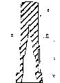
Fig. 3 is the magnification ratio that dissectd by the axial A plane of the syringe needle protective cover of this device, longitudinal section;
Fig. 4 is the transverse sectional view that the plane B by the syringe needle protective cover dissects;
Fig. 5 is an enlarged perspective in the claw of protective casing;
Fig. 6 is the transverse sectional view that the plane C by protective casing dissects;
Fig. 7 installs on the syringe of pre-filled, according to the Y-direction cutaway view of protector of the present invention; With
Fig. 8 is when taking off protective casing, the Y-direction cutaway view of injection device.
Be expressed as the integrated part of nonrecoverable injection device in the drawings according to protector of the present invention; this injection device comprises the injector housing 1 of the syringe 2 that holds a pre-filled, and this housing 1 has been equipped with the rotation of locking pre-filled syringe 2 and the device of translation.
This injection device is the type of describing among patent application FR99125000 and the FR9912501, for details can be with reference to them more specifically.
In these patent applications; describe like this; this injection device comprises an injector housing 1 that is made of a protective cover; as shown in Figure 1; this protective cover comprises two anterior tubular shells 3 and rear tubular housing 4; these two housings are used in prolongation one being contained on another, and before the traditional syringe 2 that at first is filled is installed in this protective cover, are assembled in advance.
Also describe like this in these patent applications, this injection device is combined with some elements, and elastic device wherein can cause, and when injection finished, the syringe 2 in protective cover was removed automatically.
Particularly as shown in Fig. 1 and 2, and as above-mentioned patent application described, the anterior tubular shell 3 of this protective cover comprises an alienable front waist section that is limited by easily broken annular region 6, so formed the protective cover of describing in detail later of the present invention.
As previously mentioned, the syringe 2 of the pre-filling of injection device is the syringe of traditional type, for example implements with glass, generally comprises an anterior nose 2a, and the injection needle 7 by 8 protections of syringe needle protective cover has been installed on this front portion nose.
In addition; as shown in Figure 7 and as above-mentioned patent application described, injector housing 1 is arranged to; when syringe 2 being installed in described injector housing inside, the anterior nose 2a of this syringe 2 and syringe needle protective cover 8 extend in alienable protective casing 5.
According to the present invention, at first syringe needle protective cover 8 comprises a plurality of outside longitudinal flutings 9, and they are provided with from the anterior bottom of this rear portion ring 10, wherein generally have been equipped with described syringe needle protective cover, and from described ring, roughly extending on 1/3rd of the length of syringe needle protective cover 8.
As shown in Figure 4, these outer grooves 9 are exemplified as 12 and along the longitudinal axis uniform distribution of this syringe needle protective cover 8.
In addition, this syringe needle protective cover 8 has an outer annular bossing 11, and this bossing 11 constitutes convex shoulder with the anterior end of groove 9.
The protective casing 5 of this syringe needle protective cover 8 comprises the divisible front waist section of this piped housing 3; be used for taking off easily syringe needle protective cover 8, with regard to this protective casing 5, it comprises with 6 molded inner claws 12 of described protective casing; at Fig. 2, shown in 5 and 6.
Around equally distributed 6 the inner claws 12 of the longitudinal axis of protective casing 5 at first, by an intermediate lateral hinge 13 that constitutes by the horizontal supporting leg of flexibility of the angular deflection of the described claw of control, be connected on the inner surface of transverse wall of described protective casing.
Each claw 12 comprises, at first is the forward front face surface with dihedral shape, the surperficial 14a of each in the dihedral angle, and 14b has triangular shaped, and leg-of-mutton basal edge limit has constituted the positive vertically seamed edge 15 of described dihedral angle.
Each claw 12 also comprises, a tract 16 and a Upstream section 17 of being limited by middle hinge 13.
The rear portion front face surface 18 of tract 16 has dihedral shape, and be applicable to anterior front face surface and give described tract, a Pyramid roughly, its summit constitutes the tip 19 that can penetrate in the syringe needle protective cover 8.
In addition, the front face surface at this rear portion 18 constitutes a stop surface on the transverse wall that leans against protective casing 5, can limit the rotation of the tract 16 of this claw 12.
The front face surface 20 at the rear portion of Upstream section 17 is a conjugated convex surfaces of the curve with the transverse wall of this protective casing 5 in itself, is used for forming a stop surface that limits described Upstream section rotation.
As shown in Figure 7, claw 12 is arranged to, in case syringe 2 is integrated in the injector housing 1, described most advanced and sophisticated 19 roughly are arranged on convex shoulder 11 upstreams of syringe needle protective cover.
In addition, claw 12 is configured as, and the diameter of a circle that is limited by the tip 19 of described claw is less than the diameter of syringe needle protective cover 8, so that when inserting the syringe needle protective cover in protective casing 5, this syringe needle protective cover can make claw 12 rotations.
At last, as shown in Figure 7, the positive vertically seamed edge 15 of the stop surface of tract 16 18 and each claw 12 is shaped as, in case when this syringe 2 is inserted in the injector housing, described front seamed edge is extended in parallel on the periphery wall of syringe needle protective cover 8.
According to notion of the present invention; when in injector housing 1, inserting syringe 2; syringe needle protective cover 8 will contact with the tip 19 of claw 12, and cause the rotation of described claw, till taking the stop surface 18 of the tract 16 of claw to block protective casing 5 transverse wall.
When rotation, the tip 19 of claw 12 will be thrust in the syringe needle protective cover 8, roughly in the upstream of the convex shoulder 11 of syringe needle protective cover 8.In addition, vertical seamed edge 15 of claw 12 is accommodated in the groove 9 of syringe needle protective cover 8.
Then, when taking off protective casing 5, for a shot, each claw 12 is being with along opposite spin, so that penetrating of the tip of claw 19 increases and cause guaranteeing control to syringe needle protective cover 8.
Have, when withdrawing from, relatively rotating of locking syringe needle protective cover 8 and protective casing 5 is that engagement by being formed in the groove 9 guarantees, in groove, held the front seamed edge 15 of claw 12 again.The convex shoulder 11 of protective casing 5 has guaranteed the relative translation of locking syringe needle protective cover 8 and protective casing in itself.
At last, the stop surface of the Upstream section 17 of each claw 12 in order to limit the rotation of this claw 12, is avoided the possible revolution of described claw, and therefore claw is locked in the syringe needle protective cover 8.
As example, the initial diameter that is limited by the tip 19 of claw 12 is 4 millimeters.This diameter is 5 millimeters in the spacing position of the tract 16 of claw 12, in the spacing position of the Upstream section 17 of described claw, is 3 millimeters then.
Claims (11)
1. the protector of the syringe needle (7) of syringe (2); it comprises the protective casing (5) that syringe needle protective cover (8) that a flexible material is made and rigid material are made; this protective casing (5) is used for covering syringe needle protective cover (8); and be equipped with the inside clamping device (12) of described syringe needle protective cover; when taking off protective casing; this clamping device can be controlled the syringe needle protective cover; described protector is characterised in that; be arranged on the inside clamping device in the protective casing (5); comprise at least one vertical claw (12); claw is by the horizontal supporting leg of a flexibility; and connect together with the transverse wall of protective casing (5); the horizontal supporting leg of this flexibility forms a kind of hinge, and this hinge vertically limits:
A vertical section in downstream (16); this tract has the free end of tip (19) shape that can thrust in the syringe needle protective cover; this free end is arranged in when inserting syringe needle protective cover (8) in the protective casing (5) and contacts with the syringe needle protective cover; and control the inclination of this claw (12); described downstream vertically section comprises a rear portion front face surface (18) on the transverse wall that leans against described protective casing; be used to limit described inclination
A vertical section in upstream (17), it has been equipped with the rear portion front face surface (20) on the transverse wall that leans against protective casing, is used for limiting the reversed dip of each claw (12) when taking off described protective casing (5).
2. protector according to claim 1; it is characterized in that; each claw (12) comprise one contact with this syringe needle protective cover (8) be called forward front face surface; therefore have define before the vertical dihedral shape of seamed edge (15), before this vertically seamed edge be arranged to the downstream of described claw vertically the syringe needle protective cover in the spacing position of section (16) closely contact.
3. protector according to claim 2; it is characterized in that; the tract (16) of each claw (12) comprises the front face surface (18) that is called the rear portion; it has the dihedral shape that defines a vertical seamed edge, and this vertical seamed edge is with vertical seamed edge of the forward front face surface of this claw taper off to a point (19).
4. according to claim 2 or 3 described protectors; wherein this syringe needle protective cover (8) has truncated cone shape; it is characterized in that; preceding vertical seamed edge (15) of each claw (12) is arranged to; in the spacing position of the tract (16) of described claw, parallel with the periphery wall of described syringe needle protective cover.
5. protector according to claim 2 is characterized in that, this syringe needle protective cover (8) comprises a plurality of longitudinal flutings, and this groove can hold each preceding vertically seamed edge (15) of a claw (12).
6. protector according to claim 5 is characterized in that, each groove (9) extends on the partial-length of syringe needle protective cover (8), so that the axial spacing convex shoulder at the tip (19) of each claw (12) is set.
7. protector according to claim 6 is characterized in that, this syringe needle protective cover (8) comprises outside annular portions, and this bossing forms convex shoulder (11) with groove (9) end.
8. according to the described protector of above-mentioned claim 1, it is characterized in that protective casing (5) comprises 6 inside claws (12) around the axle distribution of described protective casing.
9. protector according to claim 5 is characterized in that, this syringe needle protective cover (8) comprises 12 grooves around the axle distribution of described syringe needle protective cover.
10. protector according to claim 1 is characterized in that, the horizontal hinge (13) of each claw (12) is arranged to, and when this claw rotated between two spacing positions of the limit, the tip of described claw was subjected to 2 millimeters lateral deflection.
11. syringe; comprise according to each described protector in the aforesaid right requirement; this protector is contained in the injector housing (1); this injector housing (1) is provided with the rotation that is used for described syringe and the locking system of translation; it is characterized in that; this injector housing (1) comprises alienable a section of being limited by easily broken zone (6), so that constitute protective casing (5).
Applications Claiming Priority (2)
| Application Number | Priority Date | Filing Date | Title |
|---|---|---|---|
| FR00/10473 | 2000-08-09 | ||
| FR0010473A FR2812817B1 (en) | 2000-08-09 | 2000-08-09 | PROTECTION DEVICE FOR A SYRINGE NEEDLE |
Publications (2)
| Publication Number | Publication Date |
|---|---|
| CN1446110A CN1446110A (en) | 2003-10-01 |
| CN1222329C true CN1222329C (en) | 2005-10-12 |
Family
ID=8853427
Family Applications (1)
| Application Number | Title | Priority Date | Filing Date |
|---|---|---|---|
| CNB018138926A Expired - Lifetime CN1222329C (en) | 2000-08-09 | 2001-06-29 | Device for protecting syringe needle |
Country Status (24)
| Country | Link |
|---|---|
| US (1) | US7094223B2 (en) |
| EP (1) | EP1317300B1 (en) |
| JP (1) | JP4603237B2 (en) |
| CN (1) | CN1222329C (en) |
| AR (1) | AR030083A1 (en) |
| AT (1) | ATE302037T1 (en) |
| AU (2) | AU2001270707B2 (en) |
| BR (1) | BRPI0112504B8 (en) |
| CA (1) | CA2417286C (en) |
| CZ (1) | CZ299748B6 (en) |
| DE (1) | DE60112770T2 (en) |
| DK (1) | DK1317300T3 (en) |
| ES (1) | ES2247145T3 (en) |
| FR (1) | FR2812817B1 (en) |
| HK (1) | HK1056126A1 (en) |
| HU (1) | HU226574B1 (en) |
| MX (1) | MXPA03001074A (en) |
| NZ (1) | NZ523986A (en) |
| PL (1) | PL216226B1 (en) |
| PT (1) | PT1317300E (en) |
| RU (1) | RU2243001C2 (en) |
| TW (1) | TW499315B (en) |
| WO (1) | WO2002011799A1 (en) |
| ZA (1) | ZA200301005B (en) |
Families Citing this family (59)
| Publication number | Priority date | Publication date | Assignee | Title |
|---|---|---|---|---|
| GB2414403B (en) | 2004-05-28 | 2009-01-07 | Cilag Ag Int | Injection device |
| GB2414775B (en) | 2004-05-28 | 2008-05-21 | Cilag Ag Int | Releasable coupling and injection device |
| GB2414400B (en) | 2004-05-28 | 2009-01-14 | Cilag Ag Int | Injection device |
| GB2414401B (en) | 2004-05-28 | 2009-06-17 | Cilag Ag Int | Injection device |
| GB2414402B (en) | 2004-05-28 | 2009-04-22 | Cilag Ag Int | Injection device |
| GB2414409B (en) | 2004-05-28 | 2009-11-18 | Cilag Ag Int | Injection device |
| GB2414399B (en) | 2004-05-28 | 2008-12-31 | Cilag Ag Int | Injection device |
| GB2414406B (en) * | 2004-05-28 | 2009-03-18 | Cilag Ag Int | Injection device |
| GB2427826B (en) | 2005-04-06 | 2010-08-25 | Cilag Ag Int | Injection device comprising a locking mechanism associated with integrally formed biasing means |
| GB2424838B (en) | 2005-04-06 | 2011-02-23 | Cilag Ag Int | Injection device (adaptable drive) |
| GB2424836B (en) | 2005-04-06 | 2010-09-22 | Cilag Ag Int | Injection device (bayonet cap removal) |
| GB2425062B (en) * | 2005-04-06 | 2010-07-21 | Cilag Ag Int | Injection device |
| GB2424835B (en) | 2005-04-06 | 2010-06-09 | Cilag Ag Int | Injection device (modified trigger) |
| DE602005018480D1 (en) | 2005-08-30 | 2010-02-04 | Cilag Gmbh Int | Needle device for a prefilled syringe |
| US20110098656A1 (en) | 2005-09-27 | 2011-04-28 | Burnell Rosie L | Auto-injection device with needle protecting cap having outer and inner sleeves |
| WO2007124474A2 (en) * | 2006-04-21 | 2007-11-01 | West Pharmaceutical Services, Inc. | Needle shield |
| GB2437923B (en) * | 2006-05-11 | 2011-11-23 | Owen Mumford Ltd | Needle tip storage and removal device |
| GB2438590B (en) | 2006-06-01 | 2011-02-09 | Cilag Gmbh Int | Injection device |
| GB2438591B (en) | 2006-06-01 | 2011-07-13 | Cilag Gmbh Int | Injection device |
| GB2438593B (en) * | 2006-06-01 | 2011-03-30 | Cilag Gmbh Int | Injection device (cap removal feature) |
| JP5216859B2 (en) * | 2007-09-25 | 2013-06-19 | ベクトン・ディキンソン・フランス・エス.エー.エス. | Automatic syringe with shielding separation with means to prove modification |
| CN101411905B (en) * | 2007-10-16 | 2012-05-30 | 上海顶尖堂生化科技有限公司 | Needle head for safety syringe |
| US8579866B2 (en) | 2008-01-11 | 2013-11-12 | Ucb Pharma, S.A. | Systems and methods for administering medication |
| GB2461086B (en) | 2008-06-19 | 2012-12-05 | Cilag Gmbh Int | Injection device |
| GB2461085B (en) | 2008-06-19 | 2012-08-29 | Cilag Gmbh Int | Injection device |
| GB2461089B (en) | 2008-06-19 | 2012-09-19 | Cilag Gmbh Int | Injection device |
| GB2461084B (en) | 2008-06-19 | 2012-09-26 | Cilag Gmbh Int | Fluid transfer assembly |
| GB2461087B (en) | 2008-06-19 | 2012-09-26 | Cilag Gmbh Int | Injection device |
| WO2010007395A1 (en) | 2008-07-18 | 2010-01-21 | Ucb Pharma S.A. | Systems for administering medication for rheumatoid arthritis patients |
| USD641078S1 (en) | 2008-12-29 | 2011-07-05 | Ucb Pharma, S.A. | Medical syringe with needle tip cap |
| WO2010142813A1 (en) | 2009-06-12 | 2010-12-16 | Novo Nordisk A/S | Drug delivery device with cap functions for needle assembly |
| USD660958S1 (en) | 2009-07-20 | 2012-05-29 | Ucb Pharma, S.A. | Device for administering medication |
| US8512295B2 (en) | 2010-08-19 | 2013-08-20 | West Pharmaceutical Services, Inc. | Rigid needle shield |
| BR112014000197B1 (en) | 2011-07-05 | 2021-03-23 | Shl Medical Ag | NEEDLE COATING REMOVAL SET |
| EP2548596A1 (en) * | 2011-07-20 | 2013-01-23 | Sanofi-Aventis Deutschland GmbH | Needle shield assembly |
| EP2768560B1 (en) * | 2011-10-17 | 2016-09-07 | SHL Group AB | Device for removing delivery member shields |
| CN102727960B (en) * | 2012-07-12 | 2013-07-10 | 合肥天一生物技术研究所 | Safe needle |
| EP2919836A2 (en) * | 2012-11-13 | 2015-09-23 | IN.Tool ApS | Protective cap for a device |
| FR3002738B1 (en) * | 2013-03-01 | 2020-11-20 | Societe De Transf Des Elastomeres A Usages Medicaux Et Industriels | NEEDLE PROTECTION DEVICE. |
| FR3002740B1 (en) | 2013-03-01 | 2016-01-08 | Transformation Des Elastomeres A Usages Medicaux Et Ind Soc D | NEEDLE PROTECTION DEVICE. |
| FR3002739B1 (en) * | 2013-03-01 | 2016-01-08 | Transformation Des Elastomeres A Usages Medicaux Et Ind Soc D | NEEDLE PROTECTION DEVICE. |
| JP6104366B2 (en) * | 2013-03-26 | 2017-03-29 | テルモ株式会社 | Elastic cap and assembly for syringe having the same |
| BR302013005134S1 (en) * | 2013-04-08 | 2015-01-20 | Cardio3 Biosciences Sa | SETTING APPLIED TO CATHETER STRAP |
| USD776805S1 (en) | 2013-04-08 | 2017-01-17 | Celyad S.A. | Injection catheter handle |
| BR302013005132S1 (en) | 2013-04-08 | 2015-01-20 | Cardio3 Biosciences Sa | CONFIGURATION APPLIED TO CATHETER HANDLE ELEMENT |
| GB2515038A (en) | 2013-06-11 | 2014-12-17 | Cilag Gmbh Int | Injection device |
| GB2515039B (en) | 2013-06-11 | 2015-05-27 | Cilag Gmbh Int | Injection Device |
| GB2515032A (en) | 2013-06-11 | 2014-12-17 | Cilag Gmbh Int | Guide for an injection device |
| GB2517896B (en) | 2013-06-11 | 2015-07-08 | Cilag Gmbh Int | Injection device |
| KR102355879B1 (en) | 2013-08-29 | 2022-01-25 | 사노피 | Cap for a medicament container |
| CA2974585C (en) * | 2015-01-26 | 2023-01-24 | Biocorp Production | Device for protecting a needle, syringe provided with such a device, and method for producing pre-filled cemented needle syringes |
| FR3041263B1 (en) * | 2015-09-23 | 2017-11-24 | Aptar Stelmi Sas | DISPENSING ASSEMBLY COMPRISING A SYRINGE AND A NEEDLE PROTECTION DEVICE. |
| WO2017089274A1 (en) * | 2015-11-27 | 2017-06-01 | Sanofi-Aventis Deutschland Gmbh | System for cap removal |
| DE102016108870A1 (en) * | 2016-05-13 | 2017-11-16 | Gerresheimer Regensburg Gmbh | Stinging agent protection device for a syringe |
| CH712753A2 (en) | 2016-07-28 | 2018-01-31 | Tecpharma Licensing Ag | Separating a needle cap from a product container and method of mounting an injection device. |
| JP7316269B2 (en) * | 2017-10-12 | 2023-07-27 | イーライ リリー アンド カンパニー | Needle shield puller for drug delivery system |
| EP3574945A1 (en) | 2018-05-31 | 2019-12-04 | Aspen Global Incorporated | Protective device comprising a protective cover with fixed claws |
| FR3084263B1 (en) * | 2018-07-27 | 2020-07-10 | Laboratoire Aguettant | ADMINISTRATION SYSTEM COMPRISING AN ADMINISTRATION DEVICE AND A PROTECTION DEVICE PROVIDED WITH A CLOSING MEMBRANE |
| US20230263963A1 (en) * | 2022-02-21 | 2023-08-24 | Becton, Dickinson And Company | Rigid Needle Shield for Prefillable Staked Needle Syringe |
Family Cites Families (8)
| Publication number | Priority date | Publication date | Assignee | Title |
|---|---|---|---|---|
| US4636201A (en) * | 1985-11-01 | 1987-01-13 | American Hospital Supply Corporation | Hypodermic syringe having a protective sheath cover |
| US4986818A (en) * | 1990-03-30 | 1991-01-22 | Becton, Dickinson And Company | Syringe assembly |
| US5098400A (en) * | 1991-02-14 | 1992-03-24 | Sherwood Medical Company | Needle shield |
| AT400303B (en) * | 1993-03-31 | 1995-12-27 | Immuno Ag | Disposable injection syringe, cannula module and cannula guard for such an injection syringe, and a syringe body |
| US5540666A (en) * | 1993-03-31 | 1996-07-30 | Immuno Aktiengesellschaft | Cannula shield and injection syringe system |
| US5665075A (en) * | 1996-07-03 | 1997-09-09 | Becton, Dickinson And Company | Method of making a needle shield assembly |
| FR2777787B1 (en) * | 1998-04-22 | 2001-04-20 | Stelmi Trading Internat | PROCESS FOR MANUFACTURING A NEEDLE PROTECTOR FOR AN INJECTION SYRINGE AND AN OVERMOLDED NEEDLE PROTECTOR OBTAINED |
| FR2799375B1 (en) * | 1999-10-07 | 2002-01-18 | Marc Brunel | SINGLE USE INJECTION DEVICE |
-
2000
- 2000-08-09 FR FR0010473A patent/FR2812817B1/en not_active Expired - Lifetime
-
2001
- 2001-06-29 AU AU2001270707A patent/AU2001270707B2/en not_active Expired
- 2001-06-29 US US10/344,099 patent/US7094223B2/en not_active Expired - Lifetime
- 2001-06-29 CN CNB018138926A patent/CN1222329C/en not_active Expired - Lifetime
- 2001-06-29 AT AT01949581T patent/ATE302037T1/en active
- 2001-06-29 ES ES01949581T patent/ES2247145T3/en not_active Expired - Lifetime
- 2001-06-29 NZ NZ523986A patent/NZ523986A/en not_active IP Right Cessation
- 2001-06-29 PL PL358840A patent/PL216226B1/en unknown
- 2001-06-29 HU HU0301310A patent/HU226574B1/en unknown
- 2001-06-29 CA CA002417286A patent/CA2417286C/en not_active Expired - Lifetime
- 2001-06-29 RU RU2003103444/14A patent/RU2243001C2/en active
- 2001-06-29 AU AU7070701A patent/AU7070701A/en active Pending
- 2001-06-29 DK DK01949581T patent/DK1317300T3/en active
- 2001-06-29 PT PT01949581T patent/PT1317300E/en unknown
- 2001-06-29 BR BRPI0112504A patent/BRPI0112504B8/en not_active IP Right Cessation
- 2001-06-29 WO PCT/FR2001/002083 patent/WO2002011799A1/en active IP Right Grant
- 2001-06-29 EP EP01949581A patent/EP1317300B1/en not_active Expired - Lifetime
- 2001-06-29 MX MXPA03001074A patent/MXPA03001074A/en active IP Right Grant
- 2001-06-29 DE DE60112770T patent/DE60112770T2/en not_active Expired - Lifetime
- 2001-06-29 CZ CZ20030329A patent/CZ299748B6/en not_active IP Right Cessation
- 2001-06-29 JP JP2002517131A patent/JP4603237B2/en not_active Expired - Fee Related
- 2001-07-27 TW TW090118420A patent/TW499315B/en not_active IP Right Cessation
- 2001-07-31 AR ARP010103645A patent/AR030083A1/en active IP Right Grant
-
2003
- 2003-02-05 ZA ZA200301005A patent/ZA200301005B/en unknown
- 2003-11-19 HK HK03108428A patent/HK1056126A1/xx not_active IP Right Cessation
Also Published As
Similar Documents
| Publication | Publication Date | Title |
|---|---|---|
| CN1222329C (en) | Device for protecting syringe needle | |
| CN1178709C (en) | Single-use injection device | |
| CN1320053A (en) | Disposable injection device designed to be pre-filled | |
| CN1202875C (en) | Automatically operable safety shield system for syringes | |
| CN1226059C (en) | Self-destructible safe syringe | |
| CN1185023C (en) | Pressure tubing with syringe holder for front installation | |
| CN1146448C (en) | Syringe with retractable needle assembly | |
| KR101175604B1 (en) | Injection device | |
| EP0734738B1 (en) | Syringe having safety needle shield | |
| CA2379409C (en) | Plunger for syringe | |
| JP5734202B2 (en) | Drug delivery device | |
| CA2527987A1 (en) | Intradermal needle | |
| CN1913932A (en) | Injection device with an improved dosing member | |
| US9623195B2 (en) | Needle assembly having slidable collar to control radial engagement of sleeve segments with injection pen threads | |
| CN204428546U (en) | There is the syringe of scalable penetration depth | |
| RU2003103444A (en) | SAFETY NEEDLE PROTECTIVE DEVICE | |
| CN1655840A (en) | Catheter and method of making a catheter | |
| KR102179345B1 (en) | Safety needle | |
| NZ229033A (en) | Radiation shielded body for holding syringe containing radioactive pharmaceutical material | |
| CN1230214C (en) | Medical needle device with winged shield for erroneous piercing prevention | |
| CA2444372A1 (en) | Intradermal needle | |
| CN1424923A (en) | Arrangement at syrine | |
| CN110072503B (en) | Integrated filling and injection cap for safety needle device | |
| CN107666932A (en) | Safety device for syringe | |
| US20130281942A1 (en) | Cartridge holder for an injection device |
Legal Events
| Date | Code | Title | Description |
|---|---|---|---|
| C06 | Publication | ||
| PB01 | Publication | ||
| C10 | Entry into substantive examination | ||
| SE01 | Entry into force of request for substantive examination | ||
| C14 | Grant of patent or utility model | ||
| GR01 | Patent grant | ||
| CP01 | Change in the name or title of a patent holder | ||
| CP01 | Change in the name or title of a patent holder |
Address after: Paris France Patentee after: Sanofi Address before: Paris France Patentee before: Sanofi-Aventis |
|
| TR01 | Transfer of patent right | ||
| TR01 | Transfer of patent right |
Effective date of registration: 20180927 Address after: Mauritius Great Bay Patentee after: Aspen Global Co.,Ltd. Address before: Paris France Patentee before: Sanofi |
|
| CX01 | Expiry of patent term | ||
| CX01 | Expiry of patent term |
Granted publication date: 20051012 |