CN1214185C - Ignition timing control device for internal combustion engine - Google Patents
Ignition timing control device for internal combustion engine Download PDFInfo
- Publication number
- CN1214185C CN1214185C CN01112489.XA CN01112489A CN1214185C CN 1214185 C CN1214185 C CN 1214185C CN 01112489 A CN01112489 A CN 01112489A CN 1214185 C CN1214185 C CN 1214185C
- Authority
- CN
- China
- Prior art keywords
- ignition timing
- ignition
- spark plug
- cylinder
- different
- Prior art date
- Legal status (The legal status is an assumption and is not a legal conclusion. Google has not performed a legal analysis and makes no representation as to the accuracy of the status listed.)
- Expired - Fee Related
Links
- 238000002485 combustion reaction Methods 0.000 title claims description 18
- 238000010304 firing Methods 0.000 claims description 10
- 230000000694 effects Effects 0.000 abstract description 9
- 101100042610 Arabidopsis thaliana SIGB gene Proteins 0.000 description 6
- 238000000034 method Methods 0.000 description 5
- 101100042615 Arabidopsis thaliana SIGD gene Proteins 0.000 description 4
- 101100294408 Saccharomyces cerevisiae (strain ATCC 204508 / S288c) MOT2 gene Proteins 0.000 description 4
- 101150117326 sigA gene Proteins 0.000 description 4
- 239000000446 fuel Substances 0.000 description 3
- 101100421503 Arabidopsis thaliana SIGA gene Proteins 0.000 description 2
- 101100042613 Arabidopsis thaliana SIGC gene Proteins 0.000 description 2
- 230000005764 inhibitory process Effects 0.000 description 2
- AMDPNECWKZZEBQ-UHFFFAOYSA-N 5,5-diphenyl-2-sulfanylideneimidazolidin-4-one Chemical compound O=C1NC(=S)NC1(C=1C=CC=CC=1)C1=CC=CC=C1 AMDPNECWKZZEBQ-UHFFFAOYSA-N 0.000 description 1
- 235000008733 Citrus aurantifolia Nutrition 0.000 description 1
- 241000339287 Ochna arborea Species 0.000 description 1
- 101100520663 Saccharomyces cerevisiae (strain ATCC 204508 / S288c) ADD66 gene Proteins 0.000 description 1
- 240000006909 Tilia x europaea Species 0.000 description 1
- 235000011941 Tilia x europaea Nutrition 0.000 description 1
- 239000000498 cooling water Substances 0.000 description 1
- 238000002347 injection Methods 0.000 description 1
- 239000007924 injection Substances 0.000 description 1
- 239000004571 lime Substances 0.000 description 1
- 239000000203 mixture Substances 0.000 description 1
- 230000001360 synchronised effect Effects 0.000 description 1
- 231100000331 toxic Toxicity 0.000 description 1
- 230000002588 toxic effect Effects 0.000 description 1
Images


Classifications
-
- F—MECHANICAL ENGINEERING; LIGHTING; HEATING; WEAPONS; BLASTING
- F02—COMBUSTION ENGINES; HOT-GAS OR COMBUSTION-PRODUCT ENGINE PLANTS
- F02P—IGNITION, OTHER THAN COMPRESSION IGNITION, FOR INTERNAL-COMBUSTION ENGINES; TESTING OF IGNITION TIMING IN COMPRESSION-IGNITION ENGINES
- F02P15/00—Electric spark ignition having characteristics not provided for in, or of interest apart from, groups F02P1/00 - F02P13/00 and combined with layout of ignition circuits
- F02P15/08—Electric spark ignition having characteristics not provided for in, or of interest apart from, groups F02P1/00 - F02P13/00 and combined with layout of ignition circuits having multiple-spark ignition, i.e. ignition occurring simultaneously at different places in one engine cylinder or in two or more separate engine cylinders
Landscapes
- Engineering & Computer Science (AREA)
- Chemical & Material Sciences (AREA)
- Combustion & Propulsion (AREA)
- Mechanical Engineering (AREA)
- General Engineering & Computer Science (AREA)
- Electrical Control Of Ignition Timing (AREA)
- Ignition Installations For Internal Combustion Engines (AREA)
- Combustion Methods Of Internal-Combustion Engines (AREA)
Abstract
The engine operating region in which the two spark plugs ignite at different ignition timings is limited to a region (ignition region with different phases): in this region, the effect of different ignition timings can be achieved significantly. In the operating region other than the upper region, simultaneous ignition can be performed. The base ignition timing IGMAPIN of the intake spark plug 8I is calculated by means of the retrieval map (S11). In the ignition region where the phase is different, the basic ignition timing igmpex of the exhaust spark plug 8E is calculated by means of the retrieval map (S13). In contrast, in the operating region where simultaneous ignition is performed, the basic exhaust ignition timing IGMAPEX is set to the basic intake ignition timing IGMAPIN (S14).
Description
The present invention relates to the igniting correct timing controller of internal-combustion engine, in this internal-combustion engine, be provided with two spark plugs for each cylinder.
Traditionally, for example, ITCS Ignition Timing Control System shown in the Japanese patent unexamined publication No.Hei.6-323230 is known, in this control system, for each cylinder of internal-combustion engine is provided with some spark plugs, and the ignition timing of these spark plugs is different mutually, thereby has improved the characteristic of toxic emission.In this system, can reduce the load on the computing element under the situation for the ignition timing that decides some spark plugs in working state according to motor.On the other hand, determine the calculating of the normal ignition timing of special spark plug, and with regard to other spark plug, ignition timing by means of according to the ignition timing of special spark plug, simple relatively formula decides.
Have in the internal-combustion engine of some spark plugs at each cylinder, but when all working state of motor, it does not always need to form different plug ignition timing mutually.Therefore, from reducing the viewpoint of the calculated load on the computing element, also has further room for improvement.
Owing to this problem has been drawn the present invention.The igniting correct timing controller that the purpose of this invention is to provide a kind of internal-combustion engine, in this internal-combustion engine, be provided with two spark plugs for each cylinder, this control gear can be controlled the ignition timing of spark plug more fully, thereby the load on the minimizing computing element, and inhibition engine knock and vibration noise have been realized effectively.
In order to realize this purpose, according to a first aspect of the invention, the ignition timing of the igniting correct timing controller controlling combustion engine of internal-combustion engine.Here, in internal-combustion engine, two spark plugs that carry out an ignition operation in a circulation at least are arranged on the diagonal of firing chamber of each cylinder.Two the different ignition timing of spark plug in predetermined work zone (this predetermined work zone is decided with load according to the rotational speed of motor) are lighted a fire, and the same ignition timing in the working zone that is not the predetermined work zone is lighted a fire.
According to this configuration, in the predetermined work zone that is determined by engine rotary speed and load, two spark plugs are lighted a fire in different ignition timing place.Simultaneously, in the working zone that is not the predetermined work zone, these spark plugs are lighted a fire in same ignition timing.In this case, predetermined work zone office is restricted to such zone: the effect that is provided with that can realize different ignition timing significantly.Therefore, can reduce load and storage volume on the computing element.In the predetermined work zone, by means of the excellent effect that different ignition timing realizes suppressing engine knock and vibration noise is set.
Such working zone preferably is arranged in the predetermined work zone: in this working zone, the rotational speed of motor is in predetermined limes superiors and the zone between the limit inferior, and the load of motor is equal to, or greater than predetermined load.By means of this method, each cylinder of motor can be divided into air inlet side and exhaust side by means of a such plane: this plane is substantially perpendicular to the direction that suction port extended in the firing chamber that is connected to cylinder.Here, this plane has cylinder centerline, and preferably, two spark plugs are arranged on air inlet side and exhaust side place separately.
Fig. 1 shows the figure of the shape of the major component of internal-combustion engine of the embodiment of the invention and control gear;
Fig. 2 is the view that illustrates the layout of spark plug in each cylinder of internal-combustion engine;
Fig. 3 shows the figure of the connection between the spark plug of electric control element ECU and cylinder;
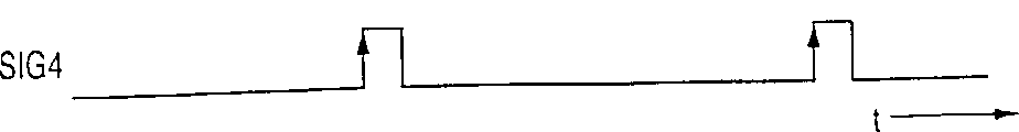
Fig. 4 is the time chart that illustrates the ignition timing in Fig. 3 configuration;
Fig. 5 is the flow chart that calculates the process of ignition timing;
Fig. 6 illustrates the view that ignition timing is set according to the operating range of motor;
Fig. 7 shows the view of an example of the chart that is provided with for the calculating ignition timing;
Fig. 8 illustrates to suppress because the different caused engine knock of igniting of phase place and increase the view of motor output; And
Fig. 9 A is some such views to 9D: they illustrate owing to the minimizing of the maximum rate of the variable (dp/d θ MAX) of the different caused cylinder pressure of igniting of phase place and by means of this minimizing motor output are increased.
Hereinafter, embodiment with reference to the accompanying drawings to describe the present invention.
Fig. 1 shows the figure of shape of the major component of the internal-combustion engine of the embodiment of the invention and control gear.1 (abbreviating motor hereinafter as) 1 in four-cylinder internal combustion engine, each cylinder 2 has two spark plugs.Fig. 2 is the figure that looks from the top of cylinder 2, and it illustrates the shape of major component.In the figure, suction valve, outlet valve and similar structure do not illustrate.This description is carried out with reference to Fig. 1 and 2 and is got the #1 cylinder as an example.Suction port 4 is connected in the firing chamber 3 by air inlet openings 5, and relief opening 6 is connected in the firing chamber 3 by exhaust port 7.Firing chamber 3 is divided into two parts by means of plane A.When the part that is called the air inlet side and has an exhaust port 7 when the part with air inlet openings 5 was called exhaust side, two spark plug 8I1 and 8E1 were arranged on the diagonal L T of firing chamber 3.Here, two spark plug 8I1 and 8E1 correspondingly are connected on the top of firing chamber of the top, firing chamber of air inlet side and exhaust side.Diagonal L T is such straight line: it intersects with the centre line L C that extends along the axial direction Y of cylinder 2, and perpendicular to centre line L C.Plane A is substantially perpendicular to direction X, and suction port 4 extends along this direction X, as see cylinder 2 along axial direction Y.Plane A has the centre line L C that extends along the axial direction Y of cylinder 2.The #2-#4 cylinder also has analogous shape.
In being described below, all spark plugs are commonly referred to " spark plug 8 ", and the spark plug on the air inlet side is commonly referred to " air inlet spark plug 8I ", and the spark plug on the exhaust side is commonly referred to " exhaust spark plug 8E ".
Air inlet spark plug 8I1 is connected electric control element 11 (being abbreviated as ECU hereinafter) with exhaust spark plug 8E1, so their work is controlled by ECU11.
The degree in crank angle position transducer 12 of the angle of swing of the bent axle (not shown) of detecting engine 1 is connected among the ECU11, thus the corresponding to signal of angle of swing of supply and bent axle.Degree in crank angle position transducer 12 is shaped by means of following these: cylinder is adjusted sensor, and it is in the predetermined crank angle degree position of a special cylinder of motor 1 output signal pulses (being called " cyl signal pulse " hereinafter); The TDC sensor, it is (in four cylinder engine, with the interval of 180 degree) output TDC signal pulse in such degree in crank angle position: the predetermined crank angle degree of this degree in crank angle position leading upper dead center (TDC) when the aspirating stroke of each cylinder begins; And the CRK sensor, this sensor (for example in circulation of 30 degree) in the circulation of constant degree in crank angle produces a pulse (being called the CRK signal pulse hereinafter) that is shorter than the TDC signal pulse.Cyl signal pulse, TDC signal pulse and CRK signal pulse supply to ECU11.Signal pulse is used for controlling various timings such as fuel injection timing and ignition timing, and is used for the revolution NE (engine speed) of detecting engine.
In addition, the absolute pressure transducer 13 of suction tude is surveyed the absolute pressure PBA from the downstream of the throttle valve of suction tude, and this throttle valve is communicated with entry port 4, (this pressure is called " intake pipe absolute pressure " hereinafter).And unshowned other sensor (intake air temperature sensor, engine cooling water temperature sensor and analog) is connected among the ECU11.The detected signal of these sensors supplies among the ECU11.
Fuelinjection nozzle 9 is arranged in the suction port.The work of valve is controlled by means of ECU11.According to the detected signal of various sensors, the ignition timing of ECU11 control spark plug 8 and the time of opening and the timing of Fuelinjection nozzle 9.
In this embodiment, two methods that spark plug is lighted a fire have simultaneously been adopted.Therefore, the spark plug of #1, #2, #3 and #4 cylinder is connected on the ECU11, as shown in fig. 3.Specifically, the exhaust spark plug 8E4 of the air inlet spark plug 8I1 of #1 cylinder and #4 cylinder drives by means of fire signal SIG1.Similarly, the air inlet spark plug 8I4 of the exhaust spark plug 8E1 of #1 cylinder and #4 cylinder drives by means of fire signal SIG2, the exhaust spark plug 8E2 of the air inlet spark plug 8I3 of #3 cylinder and #2 cylinder drives by means of period signal SIG3, reaches the exhaust spark plug 8E3 of #3 cylinder and the air inlet spark plug 8I2 of #2 cylinder and drives by means of period signal SIG4.
Fig. 4 is a time chart, and it illustrates the ignition timing to SIG4 according to fire signal SIG1.Each timing place execution ignition operation at accompanying drawing to upward arrow.,, before the expansion stroke of the #1 cylinder of response fire signal SIG1 and SIG2 and #4 cylinder, light a fire immediately with the same shown in (b) as (a) of Fig. 4.And,,, before the expansion stroke of #3 cylinder that responds fire signal SIG3 and SIG4 and #2 cylinder, light a fire immediately with the same shown in (d) as figure (c).
Fig. 5 is the flow chart of process that calculates the ignition timing of spark plug 8.This process realizes by means of the CPU (central processing element) with the synchronous ECU11 of TDC signal pulse.In step S11, retrieve IGMAPIN figure according to the revolution NE of motor and the absolute pressure PBA of suction tude, therefore calculate the basic ignition timing IGMAPIN of air inlet spark plug 8I.Next, whether the working state of judging motor is in the different ignition zone of phase place, this ignition zone is represented with the shade under being tilted in Fig. 6, the ignition zone that this phase place is different promptly is the working zone of being scheduled to, in this predetermined working zone, the ignition timing of air inlet spark plug 8I is different from the ignition timing (step S12) of exhaust spark plug 8E.In Fig. 6, predetermined intake pipe absolute pressure PBA2, PBA3 and PBA4 are configured to as 48KPa (360mmHg), 74.7KPa (560mmHg) and 101.3KPa (760mmHg), and predetermined engine speed NE1, NE2 and NE3 correspondingly are arranged to as 1000rpm, 1500rpm and 4500rpm.
When the working state of motor is in the different ignition zone of phase place, revolution NE and intake pipe absolute pressure PBA according to motor retrieve IGMAPEX figure, and calculate the basic ignition timing IGMAPEX (step S13) of exhaust spark plug 8E, control forwards among the step S15 then.Only for the different ignition zone of phase place is provided with IGMAPEX figure, and be configured to lag behind for these values of the IGMAPIN figure of the value of setting in the figure when being in identical working state.
Fig. 7 is such diagrammatic sketch: it shows engine revolution NE and IGMAPIN under the constant situation of intake pipe absolute pressure PBA and the example that the relation between the figure value is set of IGMAPEX.In the scope of engine revolution NE is 1500 under the situation of 4500rpm, and basic exhaust ignition timing IGMAPEX is arranged to lag behind.
On the contrary, when the working state of motor is in the operating range that is not in the different ignition zone of phase place when (this zone is represented by means of acclivitous shade) in Fig. 6, basic exhaust ignition timing IGMAPEX is set to the basic air inlet ignition timing IGMAPIN that calculated in step S11, this control advances to step S15 then.
In step S15, calculate correction term IGCR according to the temperature or the similar parameters of motor.Then, by means of being joined, this correction term calculates air inlet ignition timing IGLOGIN and exhaust ignition timing IGLIGEN (step S16) among basic ignition timing IGMAPIN and the IGMAPEX.
Produce fire signal SIG1 and SIG4 according to the ignition timing IGLIGIN and the IGLIGEX that therefore calculate, then these signals are supplied in the spark plug 8.
The same as mentioned above, in this embodiment, be provided with such two working zones: the working zone of lighting a fire simultaneously, at the same time in the igniting, the ignition timing IGLOGEN and the IGLOGEX that are arranged on two spark plugs in the cylinder and are air inlet spark plug and exhaust spark plug 8I and 8E equate mutually; And the working zone of carrying out the different igniting of phase place.When having only working state when motor to be in the different ignition zone of phase place, retrieve IGMAPEX figure, and when working state is in the working zone of lighting a fire simultaneously, do not carry out the figure retrieval, and basic exhaust ignition timing IGMAPEX is set to basic air inlet ignition timing IGMAPIN.In other words, the igniting that phase place is different is only carried out in the working zone of obviously realizing the igniting effect that phase place is different.Therefore, can reduce the calculated load on the CPU of ECU11, store IGMAPEX and scheme needed storage volume but also can reduce.
Next, describe in detail by means of realizing the different resulting effect of igniting of phase place with reference to Fig. 8 and 9.
Fig. 8 is such figure: it shows at engine revolution NE is that 2500rpm and working state are in the air inlet ignition timing IGLOGIN of motor under the situation of throttle full open and the relation between the output torque TRQ.In the accompanying drawings, straight line L1 shows exhaust ignition timing IGLOGEX and carries out characteristic under the best situation about being provided with according to basic air inlet ignition timing IGLOGIN, point P2 is and the corresponding to operation point of situation of being arranged to IGLOGIN=10 degree and IGLOGEX=3 degree, and on this operation point, when carrying out the different igniting of phase place, can obtain max. output torque.On the contrary, some P1 is and the corresponding to operation point of the engine knock limit (promptly be such operation point: at this place, output torque maximum under the situation that does not produce engine knock) of (IGLOGIN=IGLOGEN=6 degree) under the situation of lighting a fire simultaneously.At this example, when carrying out the different igniting of phase place, engine output torque can increase Δ TRQ1=0.2kgm and can not produce engine knock, and is because can prevent to produce engine knock by carrying out the different igniting of phase place, the same as hereinafter described.
Air-fuel mixture flows into along the arrow directions X of Fig. 2 in the firing chamber of motor 1 in 3, thereby produces clockwise eddy current.When at first carrying out lighting a fire by means of air inlet spark plug 8I1, burning advances near spark plug 8I1 the exhaust spark plug 8E1.After an air inlet spark plug 8I1, carry out the igniting of exhaust spark plug 8E1, therefore can realize normal burning (before producing engine knock) before the improper igniting that produces so-called end gas part.Therefore, the ignition timing when the engine output torque maximum can be set, and can not produce engine knock.
Fig. 9 A shows some figure of such phenomenon to 9D: when carrying out the different igniting of phase place, the high specific of the variable dp/d θ of cylinder pressure PCYL is less than the high specific under the igniting situation simultaneously (working state is under the throttle full open condition of NE=3000rpm).In the accompanying drawings, solid line is represented the characteristic of the different igniting of phase place (IGLOGIN=10 degree and IGLOGEX=3 degree), and the characteristic (IGLOGIN=GLOGEX=8 degree) of dotted line when representing to light a fire simultaneously.
The same shown in Fig. 9 A, with regard to cylinder pressure PCYL, these features are mutually near identical.On the contrary, the same shown in Fig. 9 B, the maximum dp/d θ MAX ratio of the variable dp/d θ of the igniting that phase place is different is less than the ratio of lighting a fire simultaneously.Solid line among Fig. 9 C shows basic exhaust ignition timing IGLOGEN and is fixed in relation between the maximum rate of variable dp/d θ MAX under the situations of 10 degree at air inlet ignition timing IGLOGIN, and the solid line among Fig. 9 D shows exhaust ignition timing IGLOGEX and the relation between the engine output torque TRQ under the situation of identical setting.Maximum rate that has been shown in dotted line exhaust ignition timing IGLOGEN and variable dp/d θ MAX among Fig. 9 C and the 9D and the relation between the engine output torque TRQ under the IGLOGIN=IGLOGEN situation.
In motor, when the maximum rate of variable dp/d θ MAX was big, the vibration noise level was also higher.For example, when the maximum rate of variable dp/d θ MAX is suppressed to the limit DPTH of Fig. 9 C or still less the time, compare when lighting a fire simultaneously, therefore the engine output torque during the different igniting of phase place increases Δ RTQ2.
And when carrying out the different igniting of phase place, sky-combustion is than can being arranged to less value, so fuel consumption can be enhanced and can improve the total amount of exhaust gas recirculation.Therefore, can also the improve effect of exhaust emission characteristics.
In an embodiment, ECU11 has constituted igniting correct timing controller.
The present invention is not limited to embodiment described above, but can carry out various improvement.In an embodiment, when carrying out the different igniting of phase place, air inlet ignition timing IGLOGIN is arranged to cause exhaust ignition timing IGLOGEX.The present invention is not limited to this timing relation.On the other hand, exhaust ignition timing IGLOGEX can be arranged to cause air inlet ignition timing IGLOGIN.In another alternative embodiment, thereby by means of the improper igniting of air inlet ignition timing IGLOGIN in the end gas part effect of engine knock of being inhibited of lighting a fire before producing is set.
Among the described embodiment, adopted such configuration (Fig. 3) in the above: in this configuration, two spark plugs drive by means of a fire signal.On the other hand, can adopt such configuration: in this configuration, for each spark plug produces fire signal, and spark plug correspondingly drives by means of fire signal.
As top in detail described the same, according to the present invention, come in definite predetermined work zone at rotational speed and load according to motor, two spark plugs are lighted a fire in different ignition timing.And in the working zone that is not the predetermined work zone, spark plug is lighted a fire in same ignition timing.When the predetermined work region limits become obviously to obtain different ignition timing effect regional is set the time, can reduce load and storage volume on the computing element.In predetermined working zone,, different ignition timing can obtain the fabulous inhibition engine knock and the effect of vibration noise by means of being set.
Claims (2)
1. the igniting correct timing controller of an ignition timing that is used for controlling combustion engine, in this internal-combustion engine, at least two spark plugs that carry out an ignition operation in a circulation are arranged on the diagonal of firing chamber of each cylinder, the different ignition timing of described two spark plugs in the predetermined work zone are lighted a fire, this predetermined work zone is decided according to the rotational speed and the load of motor, and the same ignition timing in the working zone that is not the predetermined work zone is lighted a fire; It is characterized in that: control gear detects ignition timing by retrieving a figure according to engine speed and load.
2. igniting correct timing controller as claimed in claim 1 is characterized in that: cylinder is divided into air inlet side and exhaust side, and described two spark plugs are arranged on air inlet side and exhaust side place separately.
Applications Claiming Priority (2)
| Application Number | Priority Date | Filing Date | Title |
|---|---|---|---|
| JP105877/2000 | 2000-04-07 | ||
| JP2000105877A JP4275289B2 (en) | 2000-04-07 | 2000-04-07 | Ignition timing control device for internal combustion engine |
Publications (2)
| Publication Number | Publication Date |
|---|---|
| CN1317640A CN1317640A (en) | 2001-10-17 |
| CN1214185C true CN1214185C (en) | 2005-08-10 |
Family
ID=18619136
Family Applications (1)
| Application Number | Title | Priority Date | Filing Date |
|---|---|---|---|
| CN01112489.XA Expired - Fee Related CN1214185C (en) | 2000-04-07 | 2001-04-06 | Ignition timing control device for internal combustion engine |
Country Status (6)
| Country | Link |
|---|---|
| US (1) | US6499460B2 (en) |
| EP (1) | EP1143142B1 (en) |
| JP (1) | JP4275289B2 (en) |
| CN (1) | CN1214185C (en) |
| DE (1) | DE60135597D1 (en) |
| TW (1) | TW502084B (en) |
Families Citing this family (14)
| Publication number | Priority date | Publication date | Assignee | Title |
|---|---|---|---|---|
| JP3706809B2 (en) * | 2001-05-17 | 2005-10-19 | 本田技研工業株式会社 | Multi-cylinder engine |
| US7778596B2 (en) | 2004-07-29 | 2010-08-17 | Qualcomm Incorporated | Airlink sensing watermarking repeater |
| BRPI0613071A2 (en) * | 2005-07-01 | 2010-12-21 | Bajaj Auto Ltd | method and system for controlling engine noise |
| JP2007092692A (en) * | 2005-09-29 | 2007-04-12 | Toyota Motor Corp | Internal combustion engine |
| DE102008003842A1 (en) * | 2008-01-10 | 2009-07-16 | Robert Bosch Gmbh | Process for burning fuel |
| US7832259B2 (en) * | 2008-06-16 | 2010-11-16 | Gm Global Technology Operations, Inc. | Fuel system diagnostics by analyzing engine crankshaft speed signal |
| US8176893B2 (en) * | 2008-08-30 | 2012-05-15 | Ford Global Technologies, Llc | Engine combustion control using ion sense feedback |
| JP5429225B2 (en) * | 2011-04-19 | 2014-02-26 | マツダ株式会社 | Spark ignition engine |
| TWI414677B (en) * | 2011-07-13 | 2013-11-11 | Kwang Yang Motor Co | Multi - cylinder internal combustion engine |
| DE102014220915B4 (en) * | 2013-11-13 | 2020-06-18 | Suzuki Motor Corporation | Ignition control device for engine |
| JP2021161974A (en) * | 2020-03-31 | 2021-10-11 | 本田技研工業株式会社 | Fuel injection control device |
| JP7119019B2 (en) * | 2020-03-31 | 2022-08-16 | 本田技研工業株式会社 | Control device for internal combustion engine |
| JP2023020228A (en) * | 2021-07-30 | 2023-02-09 | マツダ株式会社 | engine system |
| JP2023020229A (en) * | 2021-07-30 | 2023-02-09 | マツダ株式会社 | engine system |
Family Cites Families (14)
| Publication number | Priority date | Publication date | Assignee | Title |
|---|---|---|---|---|
| JPS5294911A (en) * | 1976-02-06 | 1977-08-10 | Nissan Motor Co Ltd | Two points firing engine |
| JPS6010165B2 (en) * | 1976-02-06 | 1985-03-15 | 日産自動車株式会社 | 2-point ignition engine |
| JPS6010163B2 (en) * | 1976-02-16 | 1985-03-15 | 日産自動車株式会社 | Automotive engine cylinder head |
| JPS569060Y2 (en) * | 1976-04-16 | 1981-02-27 | ||
| JPS5650146Y2 (en) * | 1977-04-29 | 1981-11-24 | ||
| GB2070135B (en) * | 1980-02-12 | 1984-02-01 | Nissan Motor | Spark-ignition internal combustion engine |
| JPS5746065A (en) * | 1980-09-01 | 1982-03-16 | Mazda Motor Corp | Ignition system of engine |
| JPS58210371A (en) * | 1982-06-01 | 1983-12-07 | Nissan Motor Co Ltd | 2-point ignition engine |
| US4452198A (en) * | 1982-06-28 | 1984-06-05 | General Motors Corporation | Compact dual spark internal combustion engine |
| JP3105235B2 (en) * | 1990-03-30 | 2000-10-30 | マツダ株式会社 | engine |
| JPH05141336A (en) * | 1991-11-22 | 1993-06-08 | Honda Motor Co Ltd | Ignition device for internal combustion engine |
| JPH06323230A (en) | 1993-05-18 | 1994-11-22 | Mazda Motor Corp | Ignition timing controller for multipoint ignition engine |
| EP0847495B1 (en) * | 1996-06-20 | 2001-10-04 | Mecel AB | Method for ignition control in combustion engines |
| JP3596325B2 (en) * | 1999-02-09 | 2004-12-02 | 日産自動車株式会社 | Idle operation control device for internal combustion engine |
-
2000
- 2000-04-07 JP JP2000105877A patent/JP4275289B2/en not_active Expired - Fee Related
-
2001
- 2001-04-06 EP EP01108776A patent/EP1143142B1/en not_active Expired - Lifetime
- 2001-04-06 TW TW090108341A patent/TW502084B/en not_active IP Right Cessation
- 2001-04-06 CN CN01112489.XA patent/CN1214185C/en not_active Expired - Fee Related
- 2001-04-06 US US09/827,373 patent/US6499460B2/en not_active Expired - Fee Related
- 2001-04-06 DE DE60135597T patent/DE60135597D1/en not_active Expired - Fee Related
Also Published As
| Publication number | Publication date |
|---|---|
| US20020038655A1 (en) | 2002-04-04 |
| EP1143142A3 (en) | 2005-04-06 |
| EP1143142B1 (en) | 2008-09-03 |
| EP1143142A2 (en) | 2001-10-10 |
| DE60135597D1 (en) | 2008-10-16 |
| US6499460B2 (en) | 2002-12-31 |
| CN1317640A (en) | 2001-10-17 |
| JP4275289B2 (en) | 2009-06-10 |
| JP2001289143A (en) | 2001-10-19 |
| TW502084B (en) | 2002-09-11 |
Similar Documents
| Publication | Publication Date | Title |
|---|---|---|
| US5988137A (en) | Controller of in-cylinder injection spark ignition internal combustion engine | |
| CN1214185C (en) | Ignition timing control device for internal combustion engine | |
| KR100310094B1 (en) | The control system of cylnder injection type internal combustion enging with pryo-ignition method | |
| US7870844B2 (en) | Control system and method for internal combustion engine | |
| CN1667255A (en) | Direct fuel injection/spark ignition engine control device | |
| KR19980019072A (en) | CONTROL SYSTEM FOR IN-CYLINDER INJECTION SPARK IGNITION INTERNAL COMBUSTION ENGINE | |
| US20080289604A1 (en) | Method and System for Controlling Engine Noise | |
| EP0849454B1 (en) | Apparatus and method for reducing torque fluctuation for lean burn combustion engine | |
| KR100269839B1 (en) | Control device of cylinder injection type spark ignition internal combustion engine | |
| JPH0270960A (en) | Control device for internal combustion engine | |
| US5975045A (en) | Apparatus and method for controlling direct injection engines | |
| US20040107947A1 (en) | Fuel injection system and control method for internal combustion engine starting time | |
| CN1158453C (en) | Engine rotation speed controller | |
| JPH11182289A (en) | Control device for cylinder fuel injection type two-cycle engine | |
| JP3264177B2 (en) | Valve characteristic control device for internal combustion engine | |
| US20200277903A1 (en) | Cylinder deactivation system and cylinder deactivation method | |
| JP3879491B2 (en) | Control device for internal combustion engine | |
| JP2006132399A (en) | Control device and control method for an engine with supercharger | |
| CN1392336A (en) | Fuel jet control system and method for IC engine | |
| JP3131895B2 (en) | Control device for multi-cylinder internal combustion engine | |
| JP2007009835A (en) | Control device for internal combustion engine | |
| JP2561282B2 (en) | Fuel injector for multi-cylinder engine | |
| JPH01211627A (en) | Control device for engine | |
| JP3519946B2 (en) | Fuel injection control device for internal combustion engine | |
| JP2000240546A (en) | Ignition control device for internal combustion engine |
Legal Events
| Date | Code | Title | Description |
|---|---|---|---|
| C06 | Publication | ||
| PB01 | Publication | ||
| C10 | Entry into substantive examination | ||
| SE01 | Entry into force of request for substantive examination | ||
| C14 | Grant of patent or utility model | ||
| GR01 | Patent grant | ||
| C17 | Cessation of patent right | ||
| CF01 | Termination of patent right due to non-payment of annual fee |
Granted publication date: 20050810 Termination date: 20100406 |