CN1208224C - Piercing cap for a container - Google Patents
Piercing cap for a container Download PDFInfo
- Publication number
- CN1208224C CN1208224C CNB008158037A CN00815803A CN1208224C CN 1208224 C CN1208224 C CN 1208224C CN B008158037 A CNB008158037 A CN B008158037A CN 00815803 A CN00815803 A CN 00815803A CN 1208224 C CN1208224 C CN 1208224C
- Authority
- CN
- China
- Prior art keywords
- container
- lid
- neck
- sealing member
- fluid
- Prior art date
- Legal status (The legal status is an assumption and is not a legal conclusion. Google has not performed a legal analysis and makes no representation as to the accuracy of the status listed.)
- Expired - Fee Related
Links
Images


Classifications
-
- B—PERFORMING OPERATIONS; TRANSPORTING
- B65—CONVEYING; PACKING; STORING; HANDLING THIN OR FILAMENTARY MATERIAL
- B65D—CONTAINERS FOR STORAGE OR TRANSPORT OF ARTICLES OR MATERIALS, e.g. BAGS, BARRELS, BOTTLES, BOXES, CANS, CARTONS, CRATES, DRUMS, JARS, TANKS, HOPPERS, FORWARDING CONTAINERS; ACCESSORIES, CLOSURES, OR FITTINGS THEREFOR; PACKAGING ELEMENTS; PACKAGES
- B65D41/00—Caps, e.g. crown caps or crown seals, i.e. members having parts arranged for engagement with the external periphery of a neck or wall defining a pouring opening or discharge aperture; Protective cap-like covers for closure members, e.g. decorative covers of metal foil or paper
- B65D41/02—Caps or cap-like covers without lines of weakness, tearing strips, tags, or like opening or removal devices
- B65D41/28—Caps combined with stoppers
-
- B—PERFORMING OPERATIONS; TRANSPORTING
- B65—CONVEYING; PACKING; STORING; HANDLING THIN OR FILAMENTARY MATERIAL
- B65D—CONTAINERS FOR STORAGE OR TRANSPORT OF ARTICLES OR MATERIALS, e.g. BAGS, BARRELS, BOTTLES, BOXES, CANS, CARTONS, CRATES, DRUMS, JARS, TANKS, HOPPERS, FORWARDING CONTAINERS; ACCESSORIES, CLOSURES, OR FITTINGS THEREFOR; PACKAGING ELEMENTS; PACKAGES
- B65D51/00—Closures not otherwise provided for
- B65D51/18—Arrangements of closures with protective outer cap-like covers or of two or more co-operating closures
- B65D51/20—Caps, lids, or covers co-operating with an inner closure arranged to be opened by piercing, cutting, or tearing
- B65D51/22—Caps, lids, or covers co-operating with an inner closure arranged to be opened by piercing, cutting, or tearing having means for piercing, cutting, or tearing the inner closure
- B65D51/221—Caps, lids, or covers co-operating with an inner closure arranged to be opened by piercing, cutting, or tearing having means for piercing, cutting, or tearing the inner closure a major part of the inner closure being left inside the container after the opening
- B65D51/226—Caps, lids, or covers co-operating with an inner closure arranged to be opened by piercing, cutting, or tearing having means for piercing, cutting, or tearing the inner closure a major part of the inner closure being left inside the container after the opening the piercing or cutting means being non integral with, or not fixedly attached to, the outer closure
-
- B—PERFORMING OPERATIONS; TRANSPORTING
- B65—CONVEYING; PACKING; STORING; HANDLING THIN OR FILAMENTARY MATERIAL
- B65D—CONTAINERS FOR STORAGE OR TRANSPORT OF ARTICLES OR MATERIALS, e.g. BAGS, BARRELS, BOTTLES, BOXES, CANS, CARTONS, CRATES, DRUMS, JARS, TANKS, HOPPERS, FORWARDING CONTAINERS; ACCESSORIES, CLOSURES, OR FITTINGS THEREFOR; PACKAGING ELEMENTS; PACKAGES
- B65D47/00—Closures with filling and discharging, or with discharging, devices
- B65D47/04—Closures with discharging devices other than pumps
- B65D47/20—Closures with discharging devices other than pumps comprising hand-operated members for controlling discharge
- B65D47/24—Closures with discharging devices other than pumps comprising hand-operated members for controlling discharge with poppet valves or lift valves, i.e. valves opening or closing a passageway by a relative motion substantially perpendicular to the plane of the seat
- B65D47/241—Closures with discharging devices other than pumps comprising hand-operated members for controlling discharge with poppet valves or lift valves, i.e. valves opening or closing a passageway by a relative motion substantially perpendicular to the plane of the seat the valve being opened or closed by actuating a cap-like element
- B65D47/242—Closures with discharging devices other than pumps comprising hand-operated members for controlling discharge with poppet valves or lift valves, i.e. valves opening or closing a passageway by a relative motion substantially perpendicular to the plane of the seat the valve being opened or closed by actuating a cap-like element moving helically
-
- B—PERFORMING OPERATIONS; TRANSPORTING
- B65—CONVEYING; PACKING; STORING; HANDLING THIN OR FILAMENTARY MATERIAL
- B65D—CONTAINERS FOR STORAGE OR TRANSPORT OF ARTICLES OR MATERIALS, e.g. BAGS, BARRELS, BOTTLES, BOXES, CANS, CARTONS, CRATES, DRUMS, JARS, TANKS, HOPPERS, FORWARDING CONTAINERS; ACCESSORIES, CLOSURES, OR FITTINGS THEREFOR; PACKAGING ELEMENTS; PACKAGES
- B65D47/00—Closures with filling and discharging, or with discharging, devices
- B65D47/04—Closures with discharging devices other than pumps
- B65D47/20—Closures with discharging devices other than pumps comprising hand-operated members for controlling discharge
- B65D47/24—Closures with discharging devices other than pumps comprising hand-operated members for controlling discharge with poppet valves or lift valves, i.e. valves opening or closing a passageway by a relative motion substantially perpendicular to the plane of the seat
- B65D47/241—Closures with discharging devices other than pumps comprising hand-operated members for controlling discharge with poppet valves or lift valves, i.e. valves opening or closing a passageway by a relative motion substantially perpendicular to the plane of the seat the valve being opened or closed by actuating a cap-like element
- B65D47/243—Closures with discharging devices other than pumps comprising hand-operated members for controlling discharge with poppet valves or lift valves, i.e. valves opening or closing a passageway by a relative motion substantially perpendicular to the plane of the seat the valve being opened or closed by actuating a cap-like element moving linearly, i.e. without rotational motion
-
- B—PERFORMING OPERATIONS; TRANSPORTING
- B65—CONVEYING; PACKING; STORING; HANDLING THIN OR FILAMENTARY MATERIAL
- B65D—CONTAINERS FOR STORAGE OR TRANSPORT OF ARTICLES OR MATERIALS, e.g. BAGS, BARRELS, BOTTLES, BOXES, CANS, CARTONS, CRATES, DRUMS, JARS, TANKS, HOPPERS, FORWARDING CONTAINERS; ACCESSORIES, CLOSURES, OR FITTINGS THEREFOR; PACKAGING ELEMENTS; PACKAGES
- B65D47/00—Closures with filling and discharging, or with discharging, devices
- B65D47/04—Closures with discharging devices other than pumps
- B65D47/20—Closures with discharging devices other than pumps comprising hand-operated members for controlling discharge
- B65D47/24—Closures with discharging devices other than pumps comprising hand-operated members for controlling discharge with poppet valves or lift valves, i.e. valves opening or closing a passageway by a relative motion substantially perpendicular to the plane of the seat
- B65D47/245—Closures with discharging devices other than pumps comprising hand-operated members for controlling discharge with poppet valves or lift valves, i.e. valves opening or closing a passageway by a relative motion substantially perpendicular to the plane of the seat the valve being opened or closed by actuating a stopper-type element
- B65D47/247—Closures with discharging devices other than pumps comprising hand-operated members for controlling discharge with poppet valves or lift valves, i.e. valves opening or closing a passageway by a relative motion substantially perpendicular to the plane of the seat the valve being opened or closed by actuating a stopper-type element moving linearly, i.e. without rotational motion
-
- B—PERFORMING OPERATIONS; TRANSPORTING
- B65—CONVEYING; PACKING; STORING; HANDLING THIN OR FILAMENTARY MATERIAL
- B65D—CONTAINERS FOR STORAGE OR TRANSPORT OF ARTICLES OR MATERIALS, e.g. BAGS, BARRELS, BOTTLES, BOXES, CANS, CARTONS, CRATES, DRUMS, JARS, TANKS, HOPPERS, FORWARDING CONTAINERS; ACCESSORIES, CLOSURES, OR FITTINGS THEREFOR; PACKAGING ELEMENTS; PACKAGES
- B65D47/00—Closures with filling and discharging, or with discharging, devices
- B65D47/36—Closures with frangible parts adapted to be pierced, torn, or removed, to provide discharge openings
- B65D47/38—Closures with frangible parts adapted to be pierced, torn, or removed, to provide discharge openings with piercing means arranged to act subsequently as a valve to control the opening
-
- B—PERFORMING OPERATIONS; TRANSPORTING
- B65—CONVEYING; PACKING; STORING; HANDLING THIN OR FILAMENTARY MATERIAL
- B65D—CONTAINERS FOR STORAGE OR TRANSPORT OF ARTICLES OR MATERIALS, e.g. BAGS, BARRELS, BOTTLES, BOXES, CANS, CARTONS, CRATES, DRUMS, JARS, TANKS, HOPPERS, FORWARDING CONTAINERS; ACCESSORIES, CLOSURES, OR FITTINGS THEREFOR; PACKAGING ELEMENTS; PACKAGES
- B65D2251/00—Details relating to container closures
- B65D2251/0003—Two or more closures
- B65D2251/0006—Upper closure
- B65D2251/0015—Upper closure of the 41-type
-
- B—PERFORMING OPERATIONS; TRANSPORTING
- B65—CONVEYING; PACKING; STORING; HANDLING THIN OR FILAMENTARY MATERIAL
- B65D—CONTAINERS FOR STORAGE OR TRANSPORT OF ARTICLES OR MATERIALS, e.g. BAGS, BARRELS, BOTTLES, BOXES, CANS, CARTONS, CRATES, DRUMS, JARS, TANKS, HOPPERS, FORWARDING CONTAINERS; ACCESSORIES, CLOSURES, OR FITTINGS THEREFOR; PACKAGING ELEMENTS; PACKAGES
- B65D2251/00—Details relating to container closures
- B65D2251/0003—Two or more closures
- B65D2251/0037—Intermediate closure(s)
- B65D2251/0056—Intermediate closure(s) of the 47-type
-
- B—PERFORMING OPERATIONS; TRANSPORTING
- B65—CONVEYING; PACKING; STORING; HANDLING THIN OR FILAMENTARY MATERIAL
- B65D—CONTAINERS FOR STORAGE OR TRANSPORT OF ARTICLES OR MATERIALS, e.g. BAGS, BARRELS, BOTTLES, BOXES, CANS, CARTONS, CRATES, DRUMS, JARS, TANKS, HOPPERS, FORWARDING CONTAINERS; ACCESSORIES, CLOSURES, OR FITTINGS THEREFOR; PACKAGING ELEMENTS; PACKAGES
- B65D2251/00—Details relating to container closures
- B65D2251/0003—Two or more closures
- B65D2251/0068—Lower closure
- B65D2251/0093—Membrane
- B65D2251/0096—Membrane integral with the container
Abstract
A resealable cap (103, etc) for a container (2) is disclosed, the cap (103) having a seal piercing element (120), the liquid in the container (2) being initially separated from the piercing element (120) by a seal (122). The cap (103) includes a collar (106), a neck portion (105) and a top portion (104). The top portion (104) includes the seal piercing element (120). There is a liquid passage way through the cap (103), after the top portion (104) has been moved from an initial position to a closed position (thus piercing the seal (122)) and thence to an open position. Thereafter the cap (103) can be resealed and opened repeatedly, by movement of the top portion (104) from the open position to the closed position and vice versa. Numerous embodiments of the invention are disclosed.
Description
Technical field
The present invention relates to be used for the container cover of container, wherein said container cover comprises an element that pierces through that is used to pierce through the interior cover part of container.Described cover part can be a sealing member or a paillon foil, described container cover comprise one be used to destroy described paillon foil, setting up the device of a fluid passage from described container, and described container cover can reseal described container.
Background technology
The multiple different container container cover of (described container is used for fluid or fluid suspended thing) that is used for is arranged at present.Described container is stamped various ways, and the ring of tearing sign is for example arranged, and the lid that can reseal is screwed into the top (" inhaling drink top (sipper top) ") of lid on the container and resealable by screw thread.Described lid and container can be disposable or can be to reuse, and for example described lid has a screw thread.
Also have such container on the market, the top of wherein said container (in described container cover) is by a paillon foil or cover part sealing.Described cover part can be plastics or paper tinsel or the combination of the combination of the two, cardboard or other any material or various materials.General described sealing member is heat seal or the top that is laminated to described container, normally in order to keep container contents in germ-free condition, takes out described content until needs.Manually pierce through or discharge this sealing member and compare difficulty sometimes.Except removing the lid of container, also to there be cooresponding control effort to pierce through described sealing member, and the fluid passage of container is provided.
Can use the mechanical device that is used for the puncture through seal part, pocket knife etc.Yet when described lid was provided for the segment fluid flow passage of material in the container, these solution requirements were removed described lid, puncture through seal part and lid is reapposed on the described container.
In other open file, provided the solution of these problems.U.S. Patent No. 4638927 discloses a kind of container and has had the lid that pierces through element.Yet do not have the fluid passage by the described element that pierces through, described fluid passage (in case sealing member is pierced) provides separately, and fluid-tight do not arrived the device in the described container.
Independent sealing after destroying foil seal is provided in the U.S. Patent No. 3347410.
PCT/AU/97/00400 provides a kind of container cover, and it has movably top of part.Described container cover has the element that pierces through that the centering that is connected on the described top places.Yet described top upwards pulls up, to pierce through described sealing member and the material in the container cover is discharged in the container.Wherein do not form the interior arrangement of tearing device for marking with described lid one.In a single day described in addition foil seal is pierced, and provides fluid seal below the top of container, and described like this container can not be emptied completely.
AU40775/95 provides four or five parts of the lid of implementing following function, the initial sealing of container inner fluid, tears device for marking, piercing device, reseals and the fluid passage.The manufacturing of this parts has significantly increased the cost and the complexity of assembly, and described container can not be reused.
JP8091418 provides a kind of container cover, and it comprises the compound in a kind of fluid that can add in the container.Yet in case described compound adds in the container, described lid can not provide the fluid passage that compound is discharged container.
US5758788 also provides a kind of lid that is used for container, and described cover tape has a sealing member piercing device.Yet in described lid, after sealing member is destroyed, do not reseal the method for container.
WO99/44907 provides a kind of lid that has the cover part.Yet in case the destroyed needs of sealing member in the described container reseal the fluid in the container.In container cover, also has sealing arrangement.
US4982875 provides a kind of container cover that pierces through element and cover part that has.Yet before setting up by the fluid container passage of lid, described cover part and part lid (comprising the part that pierces through element) must be removed.
WO99/00311 provides one to pierce through element, but does not reseal device, and in case first sealing member is destroyed, can not provide the fluid passage.Therefore before fluid flowed out from container, described container cover must be removed.
US5975369 provides a kind of suction drink top female cap that has the top.Yet described lid originally can not provide in the parts that provided and tear device for marking, and piercing device can not be provided.
WO89/02399 provides a kind of lid that can reseal.Yet, in lid, do not tear device for marking by the fluid passage of lid yet.
An object of the present invention is to provide a kind of lid that is used for container, wherein said lid is carried out multiple function, it comprises and is used for fluid is remained on sealing member in the container, when with container combination, need not to remove container cover from container, described lid provides a kind of device that is used to destroy sealing member, and device for marking is torn in the fluid passage of resealable and.
A further object of the present invention provides a kind of container cover that is used for container, and it provides the another kind of useful form of said vesse lid and container.
Another purpose of the present invention provides a kind of lid and container, to provide a kind of more economical choosing that is different from the container that can get at present then.
Other aspects and advantages of the present invention will will be clearer by the following explanation of carrying out by way of example.
The invention summary
According to an aspect of the present invention, provide a kind of lid that is used for container, described container has open top and can hold a kind of fluid, and described container cover comprises that a sealing member pierces through element, and wherein:
Fluid in the described container is separated by a sealing member and the described element that pierces through at first;
Described container cover comprises:
One collar, it has and is used for container cover is fixed to device on the container in the container top around openings, is formed with a fluid passage of running through it on the described collar;
One neck;-
One top movably, it has the fluid passage of running through it, and comprises that sealing member pierces through element, wherein
Described top can be moved between three positions; Described three positions are initial position, open position and closed position; Described initial position has the sight indicator of airtight container; Wherein said top moves to described closed position from described initial position; This when mobile when carrying out for the first time; So that the described element that pierces through pierces through described seal; Therefore when described top moves to described open position from described detent position; For fluid sets up one from container to the fluid passage of covering the outside; And wherein
When described top was in the closed position, one or more parts at top were resisted against on one or more parts of neck, or are mated, being provided at the fluid-tight between top and the neck,
And wherein said lid also comprises:
Be used for the detachable apparatus that removably described top remained on the detouchable device of initial position and removably be used for the top is remained on open position, and wherein
When described top during at initial position, described fluid is sealed in the described container by described sealing member.
According to a further aspect in the invention, provide a kind of lid that pierces through that is used for said vesse, the wherein said neck and the described collar are integrally formed.
In accordance with a further aspect of the present invention, provide a kind of lid that pierces through that is used for said vesse, wherein said top and described to pierce through element integrally formed.
According to another aspect of the invention, provide a kind of aforesaid basically lid that pierces through that is used for container, the wherein said element that pierces through adopts one of following a kind of form, the edge of one or more points and one or more cusp.Preferred described or all point and/or edge are on the bottom side of the periphery sidepiece that is positioned at described top.When described or all point/edges are circumference, the bottom at described top can be optionally with the sidepiece at described top at angle.
Of the present invention one preferred aspect, a kind of lid that pierces through that is used for container is provided, wherein said sealing member is made by following a kind of material: aluminium foil, plastics, rigid plastic material, cardboard or wooden materials, the combination of plastic material and these materials.
According to a further aspect in the invention, provide a kind of lid that pierces through that is used for aforesaid container, wherein said sealing member is on the top of the described collar or form on every side.After perhaps in fluid enters container body, described sealing member is heat sealed on the top of described container.
Aforementioned cover of the present invention on the other hand in, described lid also comprises a removable cover part on the part of described lid, described cover part can also comprise the extra device for marking of tearing of known type.Described cover part can preferably be detachably fixed on the part that covers or be fixed to lid.This allow described cover part can be repeatedly on described closing the lid or take off.Perhaps described cover part is detachably fixed on the container, above lid.
In another embodiment of the present invention, above-mentioned lid is provided, wherein said top comprises cylindrical elements, it is positioned at the outside at the top of described neck, wherein when move between described open position and described off position in described top, described element cooperates in rotation or screw thread motion with the top of described neck.The screw motion at top helps to pierce through element and pierces through sealing member on the container top.
According to another aspect of the invention, provide a lid that pierces through that is used for said vesse, wherein said neck comprises cylindrical lateral portion, and it is positioned at the outside of the sidepiece at described top.
According to another aspect of the invention, a kind of lid that pierces through that is used for said vesse is provided, wherein said neck comprises the projection of a cylindrical lateral portion and a centralized positioning, with at the top when in the closed position, facing to the opening in the top or seal within open top.
Be appreciated that advantage of the present invention is by the different settings of neck projection and top-portion apertures, can set up multi-form fluid passage, this set depend on the top whether with respect to neck in the neck inboard or outside slip.
According to a further aspect of the invention, it provides the lid that pierces through of said vesse, and wherein said sealing is pierced through element and comprised a tip, and it is placed with respect to described neck center.Described tip and described top are optionally integrally formed.
Provide a kind of lid that pierces through that is used for said vesse in one side more of the present invention, the wherein said element that pierces through is an independent element in described top, described neck can move between the two positions, upper position and lower position, and the part of the initial position at described top is formed at wherein said top, wherein
When described top during at its initial position and when moving to off position, the described element that pierces through is shifted lower position onto from upper position, and the described subsequently element that pierces through keeps or is maintained at described lower position.
In another aspect of this invention, provide a kind of lid that pierces through that is used for said vesse, wherein said initial position and described open position are the same position of top with respect to neck.
In accordance with a further aspect of the present invention, provide a kind of container, sealing member and lid, described lid are roughly as mentioned above.
In accordance with a further aspect of the present invention, provide a kind of container, sealing member and lid, adorned a kind of fluid or fluid suspended thing in the described container.
Therefore be appreciated that to be used to store various fluids that the container from high-viscosity fluid to low-viscosity fluid/fluid suspended matter can be used according to sealing member of the present invention and lid sealing.Described sealing member pierces through element and need not to remove from container lid and just can pierce through described sealing member, so described lid can be used for drawing fluid from container.The described fluid of drawing can be finished by topple over, inhale drink or extrusion fluid from container, or carries out under action of gravity.If once all fluids are not taken out from container in addition, fluid can be sealed in the container.
The accompanying drawing summary
Reference will be made to the accompanying drawings by way of example below, and it is very clear that others of the present invention will become, wherein:
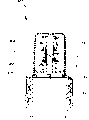
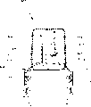
Fig. 1 is the section drawing of the lid of first preferred embodiment of the invention, and its sealing member that illustrates with described top one pierces through element, and described top is positioned at initial position;
Fig. 2 is second section drawing of first preferred embodiment of the present invention, and it illustrates described top and is positioned at off position;
Fig. 3 is the section drawing of the lid of Fig. 2, and described top is positioned at open position,
It is in the closed position that Fig. 4 illustrates the lid of Fig. 2, and position, described cover part thereon;
Fig. 5-7 illustrates second preferred embodiment of lid of the present invention, and the position of lid corresponds respectively to Fig. 1, and in 3 and 4 the position of the lid of first preferred embodiment;
Fig. 8-10 illustrates the 3rd preferred embodiment of lid of the present invention, and the position of lid corresponds respectively to Fig. 1, and in 3 and 4 the position of the lid of first preferred embodiment;
Figure 11-12 illustrates the 4th embodiment of lid of the present invention, and its position is corresponding to the position in Fig. 1 and Fig. 2 covered of first embodiment;
Figure 13 and 14 illustrates the 5th embodiment of lid of the present invention, and its position is corresponding to the position in Fig. 1 and Fig. 3 covered of first embodiment;
Figure 15-17 illustrates the 6th embodiment of lid of the present invention, and the position of lid corresponds respectively to Fig. 1, and in 3 and 4 the position of the lid of first preferred embodiment;
Figure 18-20 illustrates the 7th embodiment of lid of the present invention, and the position of lid corresponds respectively to Fig. 1, and in 2 and 3 the position of the lid of first preferred embodiment;
Figure 21-23 illustrates the 8th embodiment of lid of the present invention, and the position of lid corresponds respectively to Fig. 1, and in 2 and 3 the position of the lid of first preferred embodiment;
Figure 24-25 illustrates the 9th embodiment of lid of the present invention, and its position is corresponding to the position in Fig. 3 and Fig. 4 covered of first embodiment;
Figure 26-27 illustrates the tenth embodiment of lid of the present invention, and its position is corresponding to the position in Fig. 3 and Fig. 4 covered of first embodiment;
Figure 28-29 illustrates the 11 embodiment of lid of the present invention, and its position is corresponding to the position in Fig. 3 and Fig. 4 covered of first embodiment.
Most preferred embodiment of the present invention
The present invention is described in detail with reference to first preferred embodiment shown in Fig. 1-4.Parts identical with parts among first embodiment in all the other preferred embodiments are denoted by the same reference numerals, unless description is arranged in addition.
With reference to accompanying drawing 1-4, first preferred embodiment of container cover 103 of the present invention illustrates with container 2.Described container 2 is only represented by the top of container that described container has the sidepiece 12 around the opening of container top.What described opening was total is represented by numeral 13.Described container cover 13 comprises a screw thread, and it conforms to screw thread on the outside of the sidepiece 12 of container 2.Perhaps, described container cover 13 can be snapped to the top of container 2, and described sidepiece 12 side and the outside within it all is straight, described interlock can be known type and can operate in a known manner.As required, this cooperation can be releasable interlock or the interlock that can not unclamp.
Therefore described container cover 103 can be coupled on the container 2 with the form of screw thread or interlock, and described as required container cover can be reused maybe and can not reuse.
As shown in the figure, described container cover 103 has (optional then) cover part 4, a neck 105 and a collar portion 106.Described collar portion 106 comprises above-mentioned screw thread, is used for container cover 103 is connected to described container 2.Described collar portion 106 also comprises always upper lateral part 116 (its diameter is identical with the diameter of the sidepiece of container 2, or less than the diameter of container side).Described collar portion 106 includes the projection of projection 117, and described projection just is close to circular portion 118 places of level at the top of collar portion.As required, described protruding 117 can be continuous or interrupted around the circular portion 118 of described level.
Described cover part 4 comprises the bottom with projection 117 shaped upper part complementation.Therefore, described cover part 4 can by its detouchable with the projection 117 of collar portion 106 cooperate, with container cover 103 removably one cooperate.
Described neck 105 comprises cylindrical lateral portion 115.At the top of described neck 105 are a circular protrusions or positive stop hooks 108 outwardly.As required, described circular protrusions 108 can be continuous or interrupted around described neck 105.
That separate mutually with described annular arrangement projection 108 and what be adjacent is first projection 112 around the sidepiece 115 of described neck 105.Separate with described first projection 112 and be annular recessed portion 110, one second projectioies 111 (similar) and one second annular recessed portion 110 with projection 112 in its underpart.Described first and second projectioies (112,111) can be annular, and it can be continuous or interrupted around described annular as required.
Be separated with described circular protrusions 108 and what be adjacent is first projection 112 around the sidepiece 115 of neck 105.Be separated with described first projection and what be positioned at its below is annular recessed portion 110, one second projectioies 111 (its type is similar with protruding 112) and one second annular recessed portion 110.Described first and second projectioies (112,111) can be annular and around described ring, be continuous or be interrupted.
Described container cover 103 also comprises a top 104.Described top 104 has the sidepiece 114 of diameter greater than the diameter of the sidepiece 115 of described neck 105.Comprise a projection 119 inwardly in the bottom of described sidepiece 114, when described top 104 is positioned at initial position (as shown in Figure 1), described protruding 119 stop described top 104 easily to be removed from neck 105.Described protruding 112 and recessed portion 110 cooperate top bump 119, remain on described initial position to allow described top 104.The flexibility of the sidepiece 114 at described top 104 should be enough, and described like this top 104 will allow described top 104 to slide on described protruding 112 and 111 along the motion of arrow A (Fig. 2) direction, and face toward horizontal surface 118 stop of described collar portion 106.
Described top 104 comprises a rounded bottom by numeral 120 expressions, and described bottom has be shaped cutting (or a splitting) edge and a puncture site 121.Described cut edge 121 is with respect to locating by the line of centers X at described neck 105 and top 104 is peripheral.
Downside at the horizontal component 118 of the described collar 106 forms a sealing member 122.When described container cover 103 is positioned at initial portion (as shown in Figure 1), described puncture site 121 is next on the described sealing member 122.Fluid in the container 103 is separated with described puncture site 121 by described sealing member 122 like this.
Described sealing member 122 can be made by any material, and in the present embodiment, described sealing member and described collar portion 106 are integrally formed, and are made by same material.
Except above-mentioned fluid seal, also can add extra sealing arrangement if desired.The sealing arrangement that is appreciated that any known type can add on the container cover (between top and neck) to and/or between container cover and container.For example built-in channel can add the O shape ring of known type.
With reference to Fig. 2, shown in 3 and 4, piercing through with following steps of described container cover 103 carried out: apply downward pressure on described top 104, described like this puncture site 121 is destroyed described sealing member 122 at the point of connection place of the horizontal component 118 of the sealing member 122 and the collar 106.When applying downward pressure in the direction of arrow A (as shown in Figure 2), the center part 123 at described top 104 provides stability to described top 104.
Described top 104 can (arrow B Fig. 3) be pulled out in the upward direction.The projection inwardly 119 at the described top 104 of described second projection, 111 restrictions also stops motion upwards.This makes described top 104 be limited in open position, i.e. position between initial position and the described off position (Fig. 2).At described open position, set up a fluid passage (in Fig. 3 by shown in the arrow), when described container during towards upper shed, and the fluid in the described container 2 can be crossed the end face at described top 104 by the orifice flow that is provided with around the cover part 4.When described container cover 103 during once more for detent position (as shown in Figure 4, apply power in the direction of arrow C), described top 104, the fluid passage between the described neck 105 and the described collar 106 is sealed by the top of sidepiece 115, and described sidepiece is shaped as and can be engaged in the described hole 124.
In addition, the flange 125 in the outside of sidepiece that is placed on described puncture site 121 at the top of described element against the inside face of the sidepiece 115 of described neck 105, or the part of inside face.Be coupled in the hole 124 at described top 104 against the inside top of the sidepiece 115 of described neck 105 and the shaping top of sidepiece 115 by flange 125 thus, set up fluid sealing.Described hole 124 can be extraly as realizing that top 104 is on neck 105 or and the guide of the correct cooperation of neck 105.
In the embodiment shown in the accompanying drawing 1-4, the angled sides at described top 104 (downward-sloping towards puncture site 121) is symmetrical, and a surface of described like this sidepiece 119 is resisted against on the inside face of sidepiece 115 at described top 105 towards puncture site 121 downwards.This is another feature except that flange 125.Yet be appreciated that described flange 125 can be an annular completely, and can omit that described like this flange 125 is exactly an annular completely against the face 119 of the described piercing device of the inside face of the sidepiece 115 of described neck 105.
Shown in Fig. 1-4, described lid 4 can select then.Even cover part 4 is arranged, also can between the collar 106 and cover part 4, provide the extra device for marking (not shown) of tearing in known manner.A shrink wrap sealing member for example can be provided if desired.
The described collar 106 and described neck 105 are integrally formed with sealing member 122.These elements are made by plastic material.If desired, can be in the zone that a pre-reduction can be set on the described sealing member 122, between the edge of the horizontal flanges 118 of described collar portion 106 and described sealing member 122.
As shown in the figure, the substrate 120 at described top 104 roughly is a level.Yet be appreciated that under the prerequisite that does not depart from the scope of the present invention, this shape can change.
As learning from prior art, a described part that is used for the fluid-tight of the lid 103 on the container 2, between the described collar 106 and the described container 2 be in known manner, by the top that the collar 106 (just will cover 103) is firmly screwed into described container 2 between the top of described container and the described collar 106, to provide sealing to provide.Usefulness 126 total among the described Fig. 4 of being sealed in is represented.
Shown container 2 comprises that the outside at container 2 is right after the flange outwardly 127 (Fig. 4) under the end of the collar 106.Yet be appreciated that this is an optionally feature, can according to the shape of the collar, the collar 106 and container 2 cooperate and total structural strength at the top of container 2 changes.
It will be understood by those skilled in the art that described container 2 can newly cover 103 with one and reuse, described lid 103 has sealing member 122 therein.No matter described lid 103 whether interlock or screw thread fit all is this situation to described container 2.
Fig. 1-the 4th, the section drawing of lid 103, described neck 105 is shown for it and place at 104 centers, top.Yet be appreciated that described neck 105 and described top 104 the position can with the longitudinal center line (not shown) misalignment of described container 2.
Referring to second preferred embodiment of the present invention, it is shown in the accompanying drawing 5-7.In this embodiment, described lid 203 comprises lid 4, the collar 106, neck 205 and a top 204.Described cover part 4 is coupled on the described lid 203 in the mode identical with first embodiment 103 of lid.
The sidepiece 215 of described neck 205 has a diameter, and it is greater than the diameter of the sidepiece 214 at described top 204.Described top 204 is two independent parts, 204a and pierces through element 204b.Described piercing device 204b comprises described puncture site 221, its line of centers with respect to described lid 203 (Fig. 5) periphery location.
Promote described top 204 along the downward motion of arrow A direction (Fig. 6).This shifts described slidably puncture site 221 onto a lower position (Fig. 6), destroys described sealing member 222.Described neck 205 comprises the projection 221 of a centralized positioning, describedly raises into formation and can cooperate with the hole 224 (Fig. 7) at described top 204.
In case described sealing member 222 by top 204 move downward and the effect of puncture site 221 destroys, will produce the fluid stream shown in Fig. 7 arrow.Described fluid flow is crossed the center at described top 204, and the projection 221 of walking around described centralized positioning is then by the hole 224 in the described top 204.
As shown in Figure 6, after initial motion, the projection 220 by neck 105 with the cooperating of hole 224 at top 204 provide fluid-tight (as Fig. 5, shown in 6 and 7).The sidepiece 214 at described top 204 also cooperates with the sidepiece 215 of neck 205 and is resisted against on the described sidepiece, the fluid-tight outside the sealing that is provided with the projection 220 that provides in the hole 224.
Described protruding 212 and 211 (Fig. 5) and neck 205 on inwardly protruding (not shown) cooperatively interact.The mode that cooperates is identical with the fit system among first embodiment.Yet be appreciated that the sidepiece 215 with described neck 205 is positioned on the outside of described top 204 sidepieces 214, these protruding positions can be in contrast to the situation of the lid 103 of first preferred embodiment.
Referring to Fig. 8-10, illustrate and cover 303 the 3rd preferred embodiment.As described in first embodiment, described top 304 comprises a point 321 that has corresponding substrate 320.Described center part 323 provides booster action and rigidity is provided to top 304 in operating process.In lid 303 embodiment, described sealing member 322 strides across the top of container 2 at point 326, between the container 2 and the collar 306 (Fig. 8).
The another kind of form of first preferred embodiment is that the flange 325 at described top 304 pierces through forming of transposition on every side described fully, and further extends towards its sidepiece downwards.Like this in case described sealing member 322 destroyed (Fig. 8), described top 304 is pulled back to open position (Fig. 9), push away downwards then so that fluid-tight as shown in figure 10 to be provided, described flange 325 is resisted against on the sidepiece 315 of described neck 305, to form the part of fluid-tight.Hole 124 in the top at described in addition top 304 cooperates the top edge of the sidepiece 315 of described neck 305, and its mode is similar to reference to the described mode of first preferred embodiment.
Figure 11-12 illustrates the 4th preferred embodiment of lid 403 of the present invention, and it illustrates the mode that mode is similar to the 3rd preferred embodiment shown in Fig. 8-10.Among the embodiment after this changes, described top 404 comprises the screw thread (by dotted line 450 and 451 expressions) of a helical or coarse pitch.Therefore described top 404 can be screwed into downwards on the described neck 405 with circular movement, and described puncture site 321 pierces through described sealing member 322.Above-mentioned circular movement pierces through invocation point 321 and the described sealing member 322 that weakens in a circular arc when it descends, help the destruction of described sealing member 322 like this.
Described lid 4 is operated in the mode identical with first preferred embodiment.When described container cover 403 was opened, the fluid passage in the 3rd preferred embodiment of described fluid passage and container cover 303 was identical.
With reference to Figure 13-14, the 5th preferred embodiment 503 of container cover 503 of the present invention is shown.In this embodiment, the initial position at described top 504 is identical with open position.Described projection and neck 505 are with said vesse lid 4 with container cover 503 is placed on the identical mode of device operating mode on the container 2 operates.
In the present embodiment, described sealing member 522 is placed on the bottom of neck 505 obliquely.The sidepiece 515 of described neck 505 comprises a part of protruding downwards, to hold described bevelled rounded seal 522.When described top 504 is in the closed position, described flange 525 as above-mentioned first with the 3rd preferred embodiment in the same function that plays sealing arrangement.Described fluid passage is as the fluid passage in the 3rd embodiment.
With reference to Figure 15-17, the 6th preferred embodiment of the container cover 603 that has cover part 4 is shown.Described neck 605 and top 604 and top 204 and neck 205 in second preferred embodiment are same kind.Described puncture site 122 is the parts at top 604.Described sealing member 322 is identical with sealing member in the 3rd preferred embodiment.
The described collar 606 comprises as the sidepiece 612 described at first preferred embodiment, part 116 and projection 117.As described in first preferred embodiment, described neck 605 is integrally formed with the described collar 606.Flange 618 in the middle of to the distortion of the preferred embodiment of the neck and the collar (605,606) being upwards and slope inwardly (and being horizontal flanges 118 in first preferred embodiment).Described central protuberance 620 be that being connected on the side 615 of described neck 605, in others by a flange connector 615a all is similar type in the projection shown in second preferred embodiment (projection 221) except projection 620.This set makes a fluid passage around the described flange 615a, and described fluid passage estimates it is a circle completely except that protruding 615a.
With reference to accompanying drawing 18-20, the 7th embodiment of container cover 703 is shown.Described cover part 4 with first preferred embodiment in cover part 4 mode identical with container cover 103 fit systems cooperate described container cover 703.As described in first preferred embodiment,, all operate in an identical manner by the inside and outside projectioies of numeral 108,112,110 and 111 expressions when described top 704 (Figure 19 arrow A) and when (Figure 20 arrow B) slides in the upward direction in a downward direction.
In the present embodiment, described puncture site 721 is positioned on the element, and this element is the moving part 723 that separates mutually with top 704 and neck 705.The sealing member of describing in the described sealing member 122 and first preferred embodiment is same kind.Described moving part 723 comprises at least one side flange 724, and when described top 704 was in initial position, described side flange bias voltage leaned against on the inboard of sidepiece 715 of described neck 705.By on the described side flange 724 on described neck 705 sidepieces 715 inside faces to projecting inward vibrating part 725, described moving part 723 is limited in initial position shown in Figure 180, and prevents its possible moving down.Described can be annular completely around the inboard of sidepiece 715 of neck 705 to projecting inward vibrating part 725, and perhaps it can be the interrupted part around in described inboard.
One up projection 727 is set at the top of described moving part 723.Described protruding 727 end faces at described top 704 cooperate described hole 734.
If therefore described moving part 723 and described top 704 all are the positions after rising, as shown in figure 18, can see so and tear sign (perhaps not having).As fruit part (723,704) position after rising not one of, need not to check the device for marking of tearing on any outside that is physically connected to described lid 703 and the container 2 so, just can see this situation by plastic covered part (perhaps under the situation that does not have cover part 4) clearly.
Between projection 727 and puncture site 721, provide extra flange 728 (part 723 is star sections).These flanges are shaped as can provide the fluid passage between the edge of flange 724,725 and projection 727 and puncture site 721.
With reference to Figure 20,, set up a fluid passage, shown in the arrow among Figure 20 along with top 704 upward movement in the direction of arrow B.When pressing described top 704 in a downward direction, described protruding 721 are arranged in described hole 734, seal described fluid passage (Figure 19).
Embodiment shown in Figure 18-20 has a flange 724, and when described moving part 723 during in lower position, described flange cooperates the bottom of the sweep 718 of the described collar 706.Yet it will be understood by those skilled in the art that described flange 728 can be same kind with flange 724, rather than the flange that is provided with just to rigidity and fluid passage are provided.
In this embodiment, the place, end that described puncture site 721 is positioned at the curved lower of described moving part 723 is disclosed.Yet though everybody is appreciated that the substrate of moving part 723, the described sidepiece that leads to puncture site 721 can be formed by part always.
With reference to accompanying drawing 21-23, the lid 803 of the 8th preferred embodiment of the present invention is shown.Described lid 803 except its sealing member 822 be pass the top of described container 2 rather than with lid 803 neck 805 and the collar 806 integrally formed, all the 7th preferred embodiment 703 with lid is identical for it.
Described embodiment also comprises two puncture site 821.Be appreciated that in all embodiments, except the 5th preferred embodiment, no matter described element whether on moving part (723,823) or described top, can have two or more puncture site be positioned at described substrate of piercing through element around.
In the 8th embodiment, when firmly making described moving element downward (shown in Figure 22 arrow A), two flanges 824 outwards eject, and described bottom protrusion 826 cooperates the bottom of the sidepiece 815 of described neck 805.In case described top 804 is moved back into open position, and described fluid passage is provided as shown in figure 23.Described arrow represents that fluid is through described protruding 821, the sealing member 822, the flange 824 that are pierced and pass near described protruding 727 opening, arrive the exterior moving direction of described container 2 through the hole in the described top 804 734.
In this embodiment, the described collar 806 comprises the flange 846 of an inner horizontal, and it supports a central protuberance that makes progress 847.Described central protuberance 848, the stop part to provide the extra described moving part 823 of prevention to move downward are provided projection 848 on described flange 824.The 8th embodiment 803 to operate in others identical with the 7th embodiment 703.
With reference to Figure 24 and 25, the lid 903 of the 9th embodiment is shown.In this embodiment, described sealing member piercing device 921 and described top 904 are integrally formed.
At least two holes 129 of passing it are arranged at described top 912.The quantity in described hole 129 can be increased to four or more as required.One down tip 920 is integrally formed with the downside at described top 912.Described most advanced and sophisticated 920 have an end 921 that is shaped, and if desired, described end can be sharp.As shown in figure 33, described most advanced and sophisticated 920 have the criss cross cross section.Perhaps described if desired most advanced and sophisticated 920 can have other section form, for example circular.
Described neck 905 comprises the projection 211 of at least one shaping.Described protruding 211 number and shape be with top 904 in hole 124 complementations.Therefore be in the position of closing when described top 904, described protruding 211 enter in the hole 124 and form fluid-tight between the outside of outside and described container 2 of described container 2.When described top 904 is positioned at off position, the flange 925 by top 904 provides fluid-tight.Described flange 925 leans against the intilted circular sidepiece 915 of described neck 905.Described flange 925 is inverted truncated cone shapes.
Referring to Figure 26 and 27, tenth embodiment of the invention 1003 is shown.Described top 1004 and described paper tinsel piercing device 1021 are integrally formed.
1003 mechanism identical with the sixth embodiment of the present invention (Figure 15-17) is covered in opening and closing, forms the lower edge at described top 1004 except described point 1021.The sidepiece at described top 1004 is along cutting to point 1021 bevelled oblique sections.
In the 9th and the tenth embodiment, described lid (903,1003) is two-part, and described open position also is the initial position of described top (904,1004) as the 7th and the 8th embodiment (703,803) of described lid.
With reference to Figure 28 and 29, the lid 1103 of the 11 preferred embodiment of the present invention is shown.Described top 1104 and described paper tinsel piercing device 1121 form two independent parts, as the lid 703 in the 7th preferred embodiment.Described top 1104 has two positions, described initial position as described in each embodiment with as described in open position identical.
Described protruding 1124 up, is positioned at the sidepiece 1115 of described neck 1105.When described top 1104 of downward promotion and described moving part 1123, these projectioies are through the bottom of the sidepiece 1115 of described neck 1105, and described protruding 1124 eject.Described fluid passage is set up in the mode identical with lid 703 among the 7th embodiment.
Described retainer 1125 is dimensioned to and can prevents that by the projection on the described sidepiece 1115 it from further moving down.Described sealing member breaking plant comprises two downward projectioies 1121.
It will be understood by those skilled in the art that described sealing member breaking plant 114 also can adopt other form: two or more sawtooth; Form the sawtooth that described sealing member destroys the entire circumference of projection 1121; Interrupted sawtooth around the foot of described moving part 1124; Continuous edge around the foot of moving part 1124; Wan Qu edge structure for example, peripheral interrupted edge structure; Most advanced and sophisticated or other downward projection at the center of described sealing member breaking plant 114 (along described in-to-in transverse axis); Around the circumference or the cross section around its part be the projection of flat square; Or the combination of these forms.
Described sealing member is no matter what its material is, also no matter its position can both optionally comprise a zone, line, the zone of curve or a plurality of weakenings.Zone or line that these weaken are in advance located like this, and promptly when described paper tinsel pierced through element and begins to cooperate with sealing member, described paper tinsel piercing device and these lines or zone cooperated.The rupture strength in described zone reduces and will tear before other regional breakdown or break, and therefore described sealing member can disconnect on the regional clarity ground that uses container contents.
The different characteristic of multiple different embodiment has been described above.Be appreciated that (those skilled in the art are known) can make up it with mode and the method that changes, so under the premise of not departing from the present invention, can then go out some features from an embodiment choosing, and these features are attached on some features of another embodiment.
Claims (18)
1. lid that is used for container, described container has open top and can hold fluid, and described lid comprises that a sealing member pierces through element, wherein:
Fluid in the described container pierces through element with described sealing member at first and separates mutually by a sealing member;
Described lid comprises:
One collar, the described collar have and are used for the described device that is fixed to around open-topped on the container described that covers, and are formed with a fluid passage of running through it on the described collar;
One neck;
One top, described top can be moved along the line of centers of this neck, has the fluid passage of passing it, and comprises that described sealing member pierces through element, wherein
Described top can be moved between three positions, described three positions are initial position, open position and off position, described initial position is the visual detector of leak free container, and wherein said top can move to described off position from described initial position, when described top is mobile like this, make that piercing through element pierces through described sealing member; When described top when off position moves to described open position, set up one and be used for fluid and flow to the fluid passage in the outside of lid, wherein from container
When described top is positioned at off position, one or more member abuts at described top are on one or more elements of neck, or cooperate with one or more elements of neck, so that the fluid-tight between top and the neck to be provided, and the fluid passage at this top of hermetically passing thus;
Wherein said lid also comprises:
Be used for the detachable device that removably top remained on the detachable device of described initial position and be used for removably described top being remained on described open position; And wherein
When described top was positioned at initial position, described fluid was sealed in the described container by described sealing member.
2. the lid that is used for container as claimed in claim 1, wherein said neck and described top centrally are positioned at a side of the open-topped line of centers of described container.
3. the lid that is used for container as claimed in claim 1, the wherein said element that pierces through comprises a puncture site, it is selected from: the edge of one or more points; One or more points; The combination of one or more cusps and above-mentioned edge or point.
4. the lid that is used for container as claimed in claim 3, wherein said or all points and described or all edges are the bottoms that is positioned at the cylindrical lateral portion at described top peripherally, described sidepiece portion within it is formed with the fluid passage of passing it.
5. the lid that is used for container as claimed in claim 4, the bottom at wherein said top are with respect to the sidepiece at described top at angle.
6. the lid that is used for container as claimed in claim 1, wherein said sealing member are by a kind of the making in the following material: aluminium foil; Flexiplast; Rigidity plastics; Cardboard or woodwork; And the combination of above-mentioned material.
7. the lid that is used for container as claimed in claim 1, wherein said sealing member are fixed on the top of described container, above described opening after fluid injects described container.
8. the lid that is used for container as claimed in claim 1, the wherein said sealing member and the described collar are integrally formed.
9. the lid that is used for container as claimed in claim 1, wherein said sealing member comprise at least one predetermined atenuator region, and its rupture strength is lower than the intensity of all the other materials of sealing member.
10. the lid that is used for container as claimed in claim 1, wherein said top comprises the cylindrical side parts, it is positioned at the outside at the top of described neck, wherein work as described top at described initial position and off position, when moving between described off position and the described open position, the top of described side component and described neck reverse or the screw thread motion in cooperate.
11. the lid that is used for container as claimed in claim 1, wherein said top comprises described cylindrical side parts, it is positioned at the inboard at the top of described neck, wherein work as described top at described initial position and off position, when moving between described off position and the described open position, the top of described side component and described neck reverse or the screw thread motion in cooperate.
12. the lid that is used for container as claimed in claim 1, wherein the fluid passage by described top comprises at least one hole, and described hole cooperates with projection up on the neck, and each projection all is complementary shape, when described lid is positioned at off position, form fluid-tight therebetween.
13. the lid that is used for container as claimed in claim 1, the wherein said element that pierces through is an independent element in the described top, and the described element that pierces through can move upper position and lower position between the two positions, wherein said upper position forms the part of the initial position at top, and wherein
When described top at initial position and when moving to off position, the described element that pierces through is pushed lower position to from upper position, the therefore described element that pierces through keeps or is maintained at described lower position.
14. the lid that is used for container as claimed in claim 13, wherein the fluid passage by described top comprises an opening, described opening cooperates the projection that is formed on the described top of piercing through element, described projection is complementary shape, ought describedly cover at off position like this, described opening and described projection form fluid-tight betwixt.
15. the lid that is used for container as claimed in claim 1, wherein said lid also are included in the cover part on described lid all or part of, described cover part is detachably fixed to described covering.
16. the lid that is used for container as claimed in claim 15, wherein said lid also are included in the extra device for marking of tearing that forms around described cover part and the part lid.
17. the container of a resealable, it comprises
One container, it has open top, and can be installed in a kind of fluid;
One sealing member, and the fluid in the described container pierces through element with described sealing member at first and separates mutually by a sealing member;
Described lid comprises:
One collar, the described collar have and are used for the described device that is fixed to around open-topped on the container described that covers, and are formed with a fluid passage of running through it on the described collar;
One neck;
One top, move along the line of centers of this neck at described top, has the fluid passage of passing it, and comprise that described sealing member pierces through element, wherein
Described top can be moved between three positions, described three positions are initial position, open position and off position, described initial position is the visual detector of leak free container, and wherein said top can move to described off position from described initial position, when described top is mobile like this, make that piercing through element pierces through described sealing member; When described top when off position moves to described open position, set up one and be used for fluid and flow to the fluid passage in the outside of lid, wherein from container
When described top is positioned at off position, one or more member abuts at described top are on one or more elements of neck, or cooperate with one or more elements of neck, so that the fluid-tight between top and the neck to be provided, and the fluid passage at this top of hermetically passing thus;
Wherein said lid also comprises:
Be used for the detachable device that removably top remained on the detachable device of described initial position and be used for removably described top being remained on described open position; And wherein
When described top was positioned at initial position, described fluid was sealed in the described container by described sealing member.
18. the container of resealable as claimed in claim 17 is adorned a kind of fluid or fluid suspension in the described container.
Applications Claiming Priority (6)
| Application Number | Priority Date | Filing Date | Title |
|---|---|---|---|
| NZ50117799 | 1999-11-17 | ||
| NZ501177 | 1999-11-17 | ||
| NZ50194199 | 1999-12-21 | ||
| NZ501941 | 1999-12-21 | ||
| NZ507516 | 2000-10-13 | ||
| NZ50751600 | 2000-10-13 |
Publications (2)
| Publication Number | Publication Date |
|---|---|
| CN1390176A CN1390176A (en) | 2003-01-08 |
| CN1208224C true CN1208224C (en) | 2005-06-29 |
Family
ID=27353912
Family Applications (1)
| Application Number | Title | Priority Date | Filing Date |
|---|---|---|---|
| CNB008158037A Expired - Fee Related CN1208224C (en) | 1999-11-17 | 2000-11-16 | Piercing cap for a container |
Country Status (11)
| Country | Link |
|---|---|
| US (1) | US6772910B1 (en) |
| EP (1) | EP1237797A4 (en) |
| JP (1) | JP2003514722A (en) |
| KR (1) | KR100747092B1 (en) |
| CN (1) | CN1208224C (en) |
| AU (1) | AU782107B2 (en) |
| BR (1) | BR0015646A (en) |
| CA (1) | CA2391608C (en) |
| MX (1) | MXPA02004855A (en) |
| NZ (1) | NZ512904A (en) |
| WO (1) | WO2001036289A1 (en) |
Cited By (3)
| Publication number | Priority date | Publication date | Assignee | Title |
|---|---|---|---|---|
| CN103796929A (en) * | 2012-02-24 | 2014-05-14 | 克朗斯股份公司 | Pierceable plastic closure for closing containers |
| CN107922062A (en) * | 2015-10-05 | 2018-04-17 | 利乐拉瓦尔集团及财务有限公司 | For will cover the method put on container and apply head |
| CN111806864A (en) * | 2013-07-30 | 2020-10-23 | 阿贝尔服务 | Cap for a container and container, in particular tube, in particular flexible tube for a cosmetic product, provided with said cap |
Families Citing this family (46)
| Publication number | Priority date | Publication date | Assignee | Title |
|---|---|---|---|---|
| US9452870B1 (en) | 1987-01-20 | 2016-09-27 | Michael Anderson | Two-piece double-sealed dispensing capsule with button blast and drink through feature |
| US6959841B2 (en) * | 2000-11-01 | 2005-11-01 | Vlodek James A | Closure with selectively operable dispense feature |
| GB0029354D0 (en) * | 2000-12-01 | 2001-01-17 | Procter & Gamble Technical Ct | A disposable package for a volatile liquid |
| US7261226B2 (en) | 2001-12-12 | 2007-08-28 | Portola Packaging, Inc. | Closure having rotatable spout and axially movable stem |
| US6702161B2 (en) | 2001-12-12 | 2004-03-09 | Portola Packaging, Inc. | Closure having rotatable spout and axially movable stem |
| US6571994B1 (en) | 2001-12-12 | 2003-06-03 | Portola Packaging, Inc. | Closure having rotatable spout and axially movable stem |
| WO2003051734A1 (en) * | 2001-12-18 | 2003-06-26 | Alto Plastics Limited | Sipper cap with reciprocally movable nozzle |
| WO2003099673A1 (en) * | 2002-05-28 | 2003-12-04 | Fushing Yu | Spin-opening type bottle cap for separating solute and solvent |
| US6871764B2 (en) * | 2002-07-22 | 2005-03-29 | Creaive Packaging Corp. | Beverage closure with open/close spout and protected seal surfaces |
| AU2002951977A0 (en) | 2002-10-10 | 2002-10-24 | Leo Engineering Pty Ltd | Improvements to two-part vessels |
| NZ523373A (en) * | 2002-12-20 | 2005-08-26 | Alto Plastics Ltd | Tamper evident closure assemblies |
| US8011534B2 (en) * | 2003-02-10 | 2011-09-06 | Cool Gear International, Llc | Flavoring component holding dispenser for use with consumable beverages |
| US6959839B2 (en) * | 2003-02-10 | 2005-11-01 | Donna Roth | Flavoring component holding dispenser for use with consumable beverages |
| EP1648794B1 (en) * | 2003-07-28 | 2009-06-24 | SIG Technology Ltd. | Drinking and pouring closure with a piercing cutter device for composite packagings or container and bottle spouts sealed with a film material |
| NL1024665C2 (en) * | 2003-10-30 | 2005-05-03 | Ind Ontwerpbureau Hsm B V | Closure and its related assembly are for food container, such as a bottle and comprise at least one penetrable, non-permeable material layer for fixture to seal food container |
| US7175049B2 (en) | 2004-08-17 | 2007-02-13 | Hormel Foods, Llc | Dispensing cap |
| ZA200704769B (en) * | 2004-11-04 | 2008-08-27 | Viz Entpr Llc | Multi-chamber container and cap therefor |
| US9364215B2 (en) | 2006-01-26 | 2016-06-14 | Covidien Lp | Medical device package |
| US8109396B1 (en) | 2006-03-31 | 2012-02-07 | Rexam Healthcare Packaging Inc. | Slide rails and friction surfaces for closure |
| US7815061B1 (en) | 2006-03-31 | 2010-10-19 | Rexam Closures And Containers | Friction surface for push and turn child resistant closure |
| US20080171972A1 (en) | 2006-10-06 | 2008-07-17 | Stopek Joshua B | Medical device package |
| CA2604433A1 (en) | 2006-10-06 | 2008-04-06 | Tyco Healthcare Group Lp | Medical device package including self-puncturable port |
| US20080245683A1 (en) * | 2007-04-04 | 2008-10-09 | Injexxion, Inc. | Container for Keeping Component Separate up to Their Use |
| US8151985B2 (en) * | 2007-06-22 | 2012-04-10 | Owoc Greg J | Containers for storing at least two substances for subsequent mixing |
| FR2930140B1 (en) * | 2008-04-17 | 2011-04-22 | Philippe Perovitch | DEVICE FOR STORING, EXTENDED PREPARATION AND ADMINISTRATION OF A LOW ASSAY OF ACTIVE INGREDIENT |
| US8701906B1 (en) | 2008-12-31 | 2014-04-22 | Blast Max Llc | Ingredient dispensing cap for mixing beverages with push-pull drinking spout |
| CA2682762A1 (en) * | 2009-01-30 | 2010-07-30 | Roofers World Inc. | Load sensitive snow barrier device |
| DE102009031840B4 (en) * | 2009-04-27 | 2014-09-25 | Linhardt Gmbh & Co. Kg | tube package |
| JP5518640B2 (en) * | 2010-08-31 | 2014-06-11 | 株式会社吉野工業所 | Pouring cap |
| NL2005329C2 (en) | 2010-09-08 | 2012-03-12 | Ipn Ip Bv | A closure device. |
| US8672156B2 (en) | 2011-01-25 | 2014-03-18 | Cap Craft Corp. | Bottle and cap |
| US9567142B1 (en) | 2011-05-27 | 2017-02-14 | Michael Anderson | One-piece dispensing capsule with integral plunger |
| US9067716B2 (en) | 2011-09-30 | 2015-06-30 | Federico Intriago | Cap assembly for dispensing a dispensable component and method of making and using the same |
| US9604765B2 (en) | 2013-03-14 | 2017-03-28 | Ahhmigo, Llc | Locking cap device and methods |
| KR20140129603A (en) * | 2013-04-30 | 2014-11-07 | 인텔렉추얼디스커버리 주식회사 | Effective life indicator and stopper including the same |
| DE102014016178A1 (en) * | 2014-11-03 | 2016-05-04 | Georg Menshen Gmbh & Co. Kg | Pourer of a container |
| GB2535687B (en) * | 2014-12-15 | 2019-06-05 | Nerudia Ltd | A dispenser |
| GB2545234B8 (en) | 2014-12-15 | 2019-04-10 | Nerudia Ltd | A dispenser |
| CN105197383A (en) * | 2015-10-17 | 2015-12-30 | 李红彪 | External hung absorbable and extrudable nozzle |
| CN106742657A (en) * | 2017-03-08 | 2017-05-31 | 孟州市中孚包装科技有限公司 | Containing anti-device and the bottle cap that can repeatedly seal and its application method of choking of corkage |
| CN106742665A (en) * | 2017-03-10 | 2017-05-31 | 无限极(中国)有限公司 | A kind of liquid packaging bottle and its bottle cap |
| JP7179756B2 (en) * | 2017-04-20 | 2022-11-29 | アッヴィ・インコーポレイテッド | A method of piercing the container cap and the seal covering the opening of the container |
| CN110342097A (en) * | 2019-08-07 | 2019-10-18 | 深圳市益联塑胶有限公司 | One kind matching formula beverage bottle cap |
| US11325762B2 (en) * | 2020-09-15 | 2022-05-10 | Elc Management Llc | Container-closure system |
| EP4043355A1 (en) * | 2021-02-11 | 2022-08-17 | Gerresheimer Glas GmbH | Support member for supporting a sealing of a container |
| US11820548B2 (en) * | 2021-12-07 | 2023-11-21 | David G. Perdue | Multi-compartment bottle system |
Family Cites Families (26)
| Publication number | Priority date | Publication date | Assignee | Title |
|---|---|---|---|---|
| US2066390A (en) * | 1934-07-13 | 1937-01-05 | Armstrong Cork Co | Closure for containers |
| US2859898A (en) | 1956-10-03 | 1958-11-11 | Res Lab Inc | Container and a cap therefor, by means of which a user can prepare a fresh solution or suspension and can readily dispense the same |
| US3347410A (en) | 1966-08-31 | 1967-10-17 | Schwartzman Gilbert | Mixing assemblies for applicators |
| FR1591549A (en) | 1967-11-17 | 1970-04-27 | ||
| FR2290366A1 (en) | 1974-11-08 | 1976-06-04 | Contrapac | Container for two substances mixed before use - has one substance in plastic envelope and forced into second substance by pressing on cap |
| US3924741A (en) | 1975-03-04 | 1975-12-09 | Gibson Ass Inc | Two-compartment container |
| US4234103A (en) | 1978-03-31 | 1980-11-18 | Baxter Travenol Laboratories, Inc. | Diagnostic reagent dispensing bottle |
| US4516691A (en) * | 1982-01-25 | 1985-05-14 | Trinity Foundation | Pierce turn tap |
| FR2564433B1 (en) | 1984-05-15 | 1986-10-03 | Oreal | CONTAINER FOR PACKAGING AND DISPENSING A LIQUID PRODUCT AND AT LEAST ONE SEPARATE ADDITIONAL PRODUCT DURING STORAGE |
| IT1185850B (en) | 1985-08-02 | 1987-11-18 | Zambon Spa | DROP TANK CAP FOR BOTTLES |
| BE905791A (en) * | 1986-11-19 | 1987-03-16 | Lynes Holding Sa | POURING CAP. |
| BE1000760A6 (en) | 1987-07-27 | 1989-03-28 | Lynes Holding Sa | POURING CAP DEVICE. |
| WO1989002399A1 (en) * | 1987-09-10 | 1989-03-23 | Joseph Parsons Nominees Pty. Ltd. | Cap |
| US5104008A (en) | 1990-12-03 | 1992-04-14 | Northern Engineering And Plastics Corp. | Resealable bottle cap with push-pull closure |
| IL104463A0 (en) | 1992-02-03 | 1993-05-13 | Allergan Inc | Useful product delivery apparatus |
| IT1255256B (en) * | 1992-07-24 | 1995-10-20 | Alfonso Caruana | SELF-PERFORABLE HERMATIC CLOSING DEVICE FOR BOTTLES AND SIMILAR CONTAINERS |
| JP3281730B2 (en) | 1994-09-28 | 2002-05-13 | 株式会社吉野工業所 | Two-part mixing container |
| US5758788A (en) | 1995-10-25 | 1998-06-02 | Merck & Co., Inc. | Piercing container cap |
| ES2128220B1 (en) | 1995-12-04 | 1999-12-16 | Cusi Lab | PHARMACEUTICAL CONTAINER OF TWO SEPARATE SUBSTANCES, WITH MIXING DEVICE, DOSAGE APPLICATION AND ITS ASSEMBLY PROCESS. |
| AUPO070596A0 (en) | 1996-06-27 | 1996-07-18 | Gartner, Bradley Francis | Closure cap |
| WO1998040289A1 (en) | 1997-03-12 | 1998-09-17 | Fredrick Michael Coory | Discharge cap with releasable tablet basket |
| US5975369A (en) | 1997-06-05 | 1999-11-02 | Erie County Plastics Corporation | Resealable pushable container closure and cover therefor |
| GB9713525D0 (en) | 1997-06-26 | 1997-09-03 | Smith David S Packaging | A set of parts for providing a flow path |
| ES2191420T3 (en) | 1998-03-05 | 2003-09-01 | Henkel Kgaa | PACK WITH A DISCHARGE NOZZLE. |
| EP0947433A1 (en) * | 1998-04-03 | 1999-10-06 | Tetra Laval Holdings & Finance SA | Device for opening packages of pourable food products |
| US5853109A (en) | 1998-04-29 | 1998-12-29 | Aptargroup, Inc. | Dispensing structure with displaceable penetrator and bistable cover actuator |
-
2000
- 2000-11-16 JP JP2001538250A patent/JP2003514722A/en active Pending
- 2000-11-16 CA CA002391608A patent/CA2391608C/en not_active Expired - Fee Related
- 2000-11-16 AU AU19019/01A patent/AU782107B2/en not_active Ceased
- 2000-11-16 CN CNB008158037A patent/CN1208224C/en not_active Expired - Fee Related
- 2000-11-16 EP EP00981920A patent/EP1237797A4/en not_active Withdrawn
- 2000-11-16 NZ NZ512904A patent/NZ512904A/en not_active IP Right Cessation
- 2000-11-16 KR KR1020027006262A patent/KR100747092B1/en not_active IP Right Cessation
- 2000-11-16 BR BR0015646-9A patent/BR0015646A/en not_active IP Right Cessation
- 2000-11-16 US US10/130,817 patent/US6772910B1/en not_active Expired - Fee Related
- 2000-11-16 MX MXPA02004855A patent/MXPA02004855A/en active IP Right Grant
- 2000-11-16 WO PCT/NZ2000/000229 patent/WO2001036289A1/en active IP Right Grant
Cited By (6)
| Publication number | Priority date | Publication date | Assignee | Title |
|---|---|---|---|---|
| CN103796929A (en) * | 2012-02-24 | 2014-05-14 | 克朗斯股份公司 | Pierceable plastic closure for closing containers |
| CN103796929B (en) * | 2012-02-24 | 2016-08-17 | 克朗斯股份公司 | Can punching plastic seal device for seal container |
| CN111806864A (en) * | 2013-07-30 | 2020-10-23 | 阿贝尔服务 | Cap for a container and container, in particular tube, in particular flexible tube for a cosmetic product, provided with said cap |
| CN111806864B (en) * | 2013-07-30 | 2022-06-21 | 阿贝尔服务 | Container with a lid |
| CN107922062A (en) * | 2015-10-05 | 2018-04-17 | 利乐拉瓦尔集团及财务有限公司 | For will cover the method put on container and apply head |
| CN107922062B (en) * | 2015-10-05 | 2019-10-18 | 利乐拉瓦尔集团及财务有限公司 | For that will cover the method being applied on container and apply head |
Also Published As
| Publication number | Publication date |
|---|---|
| CA2391608A1 (en) | 2001-05-25 |
| CN1390176A (en) | 2003-01-08 |
| JP2003514722A (en) | 2003-04-22 |
| WO2001036289A1 (en) | 2001-05-25 |
| BR0015646A (en) | 2002-12-31 |
| NZ512904A (en) | 2001-11-30 |
| AU1901901A (en) | 2001-05-30 |
| KR100747092B1 (en) | 2007-08-07 |
| MXPA02004855A (en) | 2006-06-23 |
| US6772910B1 (en) | 2004-08-10 |
| KR20020061617A (en) | 2002-07-24 |
| EP1237797A1 (en) | 2002-09-11 |
| AU782107B2 (en) | 2005-07-07 |
| CA2391608C (en) | 2007-05-15 |
| EP1237797A4 (en) | 2007-01-10 |
Similar Documents
| Publication | Publication Date | Title |
|---|---|---|
| CN1208224C (en) | Piercing cap for a container | |
| CN1273352C (en) | Tamper-evident closure and spout fitment for a pouch | |
| CN100347052C (en) | Closure system for a vial, vial, method of closing and filling a vial and stand for a vial | |
| CN1261060C (en) | Device for packing and brushing material especially for cosmedic material | |
| CN1103725C (en) | Inner plug and cap for liquid injection containers, and jig used to fix cap to inner plug | |
| CN1203987C (en) | Fitment having removable membrane | |
| CN1280175C (en) | Fitment and resealable dispensing closure assembly for high-pressure sealingand bi-modal dispensing | |
| CN1295000C (en) | Pack containing medicament and dispensing device | |
| RU2346869C2 (en) | Method of separation of sealing foil closing bottle neck and screw cap to this effect | |
| CN1225383C (en) | Distributing device including valve fitting and package with said dirstributing device | |
| CN1221445C (en) | Dispensing sachet by bending and method of sachet manufacture | |
| CN1191971C (en) | Cap for container and adaptor for liquid communication | |
| CN1281461C (en) | Tubular container made of synthetic resin | |
| CN1639018A (en) | Synthetic resin cap, closing device, and packaged beverage | |
| CN1780761A (en) | Synthetic resin cap, closing device, and container-packed beverage | |
| CN1133003A (en) | Syringe device for mixing two compounds | |
| CN1736809A (en) | Fluid storing container | |
| CN1856433A (en) | Dispensing closure | |
| CN1367750A (en) | Valved dispensing system for multiple dispensing streams | |
| CN1693147A (en) | Bottle cap | |
| CN1200857C (en) | Product dispenser | |
| CN1505583A (en) | A push/pull closure | |
| JP5459068B2 (en) | Material pumping device | |
| CN1646368A (en) | Method and apparatus for loading a container with a product | |
| CN1628059A (en) | Medicament container and method of manufacture thereof |
Legal Events
| Date | Code | Title | Description |
|---|---|---|---|
| C06 | Publication | ||
| PB01 | Publication | ||
| C10 | Entry into substantive examination | ||
| SE01 | Entry into force of request for substantive examination | ||
| C14 | Grant of patent or utility model | ||
| GR01 | Patent grant | ||
| C19 | Lapse of patent right due to non-payment of the annual fee | ||
| CF01 | Termination of patent right due to non-payment of annual fee |