CN1206410C - Mechanism for repair rail - Google Patents
Mechanism for repair rail Download PDFInfo
- Publication number
- CN1206410C CN1206410C CNB021301506A CN02130150A CN1206410C CN 1206410 C CN1206410 C CN 1206410C CN B021301506 A CNB021301506 A CN B021301506A CN 02130150 A CN02130150 A CN 02130150A CN 1206410 C CN1206410 C CN 1206410C
- Authority
- CN
- China
- Prior art keywords
- track
- track lifting
- drive unit
- framework
- disk
- Prior art date
- Legal status (The legal status is an assumption and is not a legal conclusion. Google has not performed a legal analysis and makes no representation as to the accuracy of the status listed.)
- Expired - Fee Related
Links
- 230000008439 repair process Effects 0.000 title claims description 7
- 230000007246 mechanism Effects 0.000 title claims description 6
- 238000005096 rolling process Methods 0.000 claims abstract description 5
- 230000001105 regulatory effect Effects 0.000 claims description 7
- 229910000831 Steel Inorganic materials 0.000 claims description 4
- 239000010959 steel Substances 0.000 claims description 4
- 230000001154 acute effect Effects 0.000 claims description 2
- 230000009975 flexible effect Effects 0.000 claims description 2
- 230000015572 biosynthetic process Effects 0.000 claims 1
- 230000009471 action Effects 0.000 description 4
- 230000000694 effects Effects 0.000 description 3
- 230000008901 benefit Effects 0.000 description 2
- 238000000034 method Methods 0.000 description 2
- 230000002159 abnormal effect Effects 0.000 description 1
- 230000008859 change Effects 0.000 description 1
- 238000004140 cleaning Methods 0.000 description 1
- 230000006835 compression Effects 0.000 description 1
- 238000007906 compression Methods 0.000 description 1
- 238000005516 engineering process Methods 0.000 description 1
- 238000005065 mining Methods 0.000 description 1
- 230000008569 process Effects 0.000 description 1
Images

Classifications
-
- E—FIXED CONSTRUCTIONS
- E01—CONSTRUCTION OF ROADS, RAILWAYS, OR BRIDGES
- E01B—PERMANENT WAY; PERMANENT-WAY TOOLS; MACHINES FOR MAKING RAILWAYS OF ALL KINDS
- E01B27/00—Placing, renewing, working, cleaning, or taking-up the ballast, with or without concurrent work on the track; Devices therefor; Packing sleepers
- E01B27/06—Renewing or cleaning the ballast in situ, with or without concurrent work on the track
- E01B27/10—Renewing or cleaning the ballast in situ, with or without concurrent work on the track without taking-up track
Landscapes
- Engineering & Computer Science (AREA)
- Architecture (AREA)
- Civil Engineering (AREA)
- Structural Engineering (AREA)
- Machines For Laying And Maintaining Railways (AREA)
- Electrical Discharge Machining, Electrochemical Machining, And Combined Machining (AREA)
- Threshing Machine Elements (AREA)
- Train Traffic Observation, Control, And Security (AREA)
- Turning (AREA)
- Jib Cranes (AREA)
- Lift-Guide Devices, And Elevator Ropes And Cables (AREA)
- Replacement Of Web Rolls (AREA)
Abstract
A machine (1) for treating a track (3) comprises a machine frame (5), supported on on-track undercarriages (4), which includes a track lifting unit (12). The latter is equipped with a tool frame (13), vertically adjustably connected to the machine frame (5) by means of lifting drives (27), on which are arranged, per rail (16) of the track (3), two pairs (23), spaced from on e another in the longitudinal direction of the rails, of lifting rollers (24) squeezable towards one another in the transverse direction of the track by means of a transverse adjustment drive (25), as well as a flanged roller (14 ) provided for rolling on a running surface (15) of the rail (16). Each pair (23) of lifting rollers (24) is designed for independent vertical adjustment with respect to the tool frame (13) by means of a vertical adjustment drive (26). A spacing- apart motion of the two lifting rollers (24), positioned adjacent one anothe r in the transverse direction of the track, is coupled to an automatic actuation of the vertical adjustment drive (26) for lowering both lifting rollers (24) with respect to the tool frame (13).
Description
Technical field
The present invention relates to the machinery that a repair rail is used.
Background technology
The paired track lifting disk of performance clamp effect and rail head form fit attaching (formschl ü ssig) together, and can be advanced continuously when making mechanical work along side roll under the rail head.If run into the very abnormal rail of obstruction or shape, tandem two pairs of track lifting disks open in succession, and by closed again again after the problematic place, so just can guarantee to have at least a pair of track lifting disk can clamp rail all the time incessantly.
No. 4893565 patents of US have been introduced a kind of tamping car.Can regulate the height of its gripping body with drive unit, so just might make folder rail hook and rail head, or selectively also with flange of rail interlock.
Summary of the invention
The purpose of this invention is to provide a kind of standard type machinery, require this mechanical energy to be easier to and cross the vicissitudinous section of rail profile more reliably.
According to the present invention, the machinery that provides a kind of repair rail to use comprises a frame that is bearing on the rail travelling mechanism, and frame is equipped with operation unit and track lifting unit; Wherein the track jack assembly has by track lifting drive unit track lifting framework that link to each other with frame, Height Adjustable; The track lifting framework is that every one steel rail of track is equipped with two pairs according to the vertical track lifting disk separated by a distance of rail, utilizes the lateral adjustments drive unit can make the track lifting disk according to laterally opening and closing relative to each other of track; The track lifting framework also is equipped with roller with rim, so as can be on rail tread rolling; Wherein, can adjust separately raise track the relatively height of framework of every pair of track lifting disk with highly regulating drive unit, and be accompanied by two according to moving separating of track track lifting disk laterally disposed adjacent one another, automatically make dynamic height and regulate drive unit, to fall two track lifting disks with respect to the track lifting framework.
The advantage of the track lifting unit of this structure is, for a pair of track lifting disk that temporarily separates by a certain obstruction or the vicissitudinous rail of section, and after crossing this place, again can be reliably and successfully closed, exactly can close up towards each other again.This point is lifted the section of track and is acquired a special sense when higher.Because when the clamp that the track lifting disk forms separates, the section of track is fallen, thereby change the buckling curve of rail.Because the track lifting disk can fall automatically, this just with simple method and very reliable mode compensated track, exactly compensated the vertical dislocation of clamping rail, thereby the track lifting disk can be on the tram of relative rail head immediately.This adjustment process is carried out automatically, thus do not need the mechanically actuated personnel to pay special notice for this reason, but also can avoid deviation takes place and in operation, safety is produced infringement.
According to a further aspect in the invention, track lifting disk disk is to after closing up, and the section of track promptly is lifted and returns to original residing position, can unimpededly proceed to guarantee operation.
Other advantage of the present invention can be referring to every claim and explanation.
Description of drawings
Hereinafter illustrate the present invention with reference to illustrated compression.In the accompanying drawing,
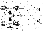
The side-looking sketch of the machinery that Fig. 1 uses for the repair rail that the track lifting unit is housed according to the present invention,
Fig. 2 and 3 is respectively the enlarged side view and the vertical view of track lifting unit,
Fig. 4 is the unit front elevation drawing that raises track longitudinally according to track.
The specific embodiment
The machinery 1 that is used for repair rail 3 railway roadbeds 2 shown in Figure 1 comprises a frame 5 that is bearing on the rail travelling mechanism 4.The operation unit 6 of circulation digger chain 7 forms of guiding to track 3 belows is housed on the frame 5, is used to excavate railway roadbed 2.Digger chain 7 is equipped with conveyer belt 8, is used to carry the ballast aggregate of collecting.In addition be used for conveyer belt 9 backfill cleaning or new ballast aggregate according to the operator to be positioned at mechanical 1 digger chain 7 back.Arrow 10 expression operators to.Other machinery 11 (not being shown specifically) even hangs over frame 5 two ends.
Have a cover track lifting unit 12 to be fixed on the frame 5 in digger chain 7 scopes, its structure will be used Fig. 2, and 3 and 4 do further displaying.Track lifting unit 12 has one according to the horizontal about horizontally extending track lifting framework 13 of track.Sliding support 17 is supported on the track lifting framework 13, utilizes the cross slide way 18 can laterally moving with respect to track lifting framework 13 according to track; Sliding support 17 links to each other with mobile drive deivce 19 for this reason.Track lifting unit 12 utilizes roller with rim 14 to be bearing on the tread 15 of track 3 rail 16 when the job position of being showed, exactly rolling on rail tread.
Be provided with control device 40 (Fig. 1) in the operating room 39, it with the lateral adjustments drive unit 25 of track lifting disk 24 with highly regulate drive unit 26 and link to each other.To drive unit 25,26 are performed such control: be exactly to be accompanied by disk to the 23 separately actions according to two track lifting disks 24 of the horizontal adjacent layout of track, highly regulate drive unit 26 automatic starts accordingly, make track lifting disk 24 fall (will be described further hereinafter) this with respect to track lifting framework 13.Can pass through control device 40 in addition, make lateral adjustments drive unit 25 for the start that realizes a disk two track lifting disks 24 of 23 are moved relative to each other with highly regulate drive unit 26 for realizing lifting the start interlock of two track lifting disks 24 with respect to track lifting framework 13.
That track lifting unit 12 or track lifting framework 13 are parallel to each other by two, about vertical extent and link to each other with frame 5 according to track track lifting drive unit 27 adjustable height ground laterally separated by a distance.In addition, track lifting framework 13 is also hinged by connector 28 and frame 5, and can pivot around a horizontal rotation axis 29 according to the track horizontal expansion.Connector 28 (being similar to parallelogram during side-looking) is similar to shafts shape by two pull bars 30 (tie rods) and one, and exactly a T shape draw bar 31 is formed.According to track laterally two pull bars 30 separated by a distance be in the common plane 32,31 of draw bars are parallel to plane 32, but it is separated by a distance and be positioned at below it with the plane.Draw bar 31 flexibles also are equipped with length adjustment drive unit 33.
When machinery 1 carries out railway roadbed 2 regulation operations, fall track lifting unit 12 and be bearing in by roller with rim 14 on the rail 16 of track 3 with track lifting drive unit 27.Then with lateral adjustments drive unit 25 or simultaneously also with highly regulating drive unit 26, with the disk of track lifting disk 24 to 23 with rail 16 form fit be connected, starting track lifting drive unit 27 subsequently once more lifts track 3, so that below track, be use operation unit 6, or say to be that usage mining chain 7 is created the necessary working spaces.
In order to make track lifting disk 24 and rail 16 realize form fit ground attachings, the length adjustment drive unit 33 of telescopic draw bar 31 is placed passive state, exactly make it be in quick condition, so that track lifting unit 12 adapts to the lengthwise position of tracks.The framework 13 that raises track this moment can rotate (Fig. 2) around axle 35 formed pivot centers 29, and this is because the lower end 37 of pull bar 30 and track lifting drive unit 27 is all hinged with axle 35 on same axis line 29.Successfully finished the adjustment of lengthwise position of track and track lifting disk 24 and reclined after the rail 16, i.e. the length adjustment drive unit 33 of locking draw bar 31, make track lifting unit 12 be stabilized in track vertically and remain on this position.
During operation, if the track lifting unit 12 of rolling runs into obstruction continuously on track 3, such as the obstruction that runs into splice bar 41 forms shown in Fig. 2 and 4, track lifting disk 24 was separated according to the horizontal short time of track, and closed again again after clearing the jumps.Each disk is pressed on together with certain pressure when the normal operation 23 track lifting disk 24.When running into obstruction, this pressure just is forced to raise, and this timed unit 40 can utilize lateral adjustments drive unit 25 to start respective circular disks automatically to moving for 23 separating of two track lifting disks 24.When the track lifting disk reached maximum position to opening, backstop 42 (Fig. 4) will start, and then causes the start of highly regulating drive unit 26, and track lifting disk 26 is fallen.
Control device 40 can be brought into play such effect at next step, such as utilizing a timing element to match with machinery 1 pace, makes track lifting disk 24 auto-closing again after through the problem location on the track 3, so that clamping rail 16 again.
Because the action of falling of track lifting disk 24 link with strutting action, thereby can guarantee to cross after the splice bar 41, under the situation of lost time not, disk is to 23 open track lifting disk 24 closure and clamping rail 16 reliably at once.For safety, second disk of follow-up track lifting disk 24 can open after to first closure 23 disks that have only the front.
Lateral adjustments drive unit 25 will make another stop 43 (Fig. 4) action after making track lifting disk 24 closures.This backstop is by the such effect of control device 40 performances, starting lateral adjustments drive unit 25 exactly makes the disk fallen can be adjacent to the rail 16 in the obstruction back two track lifting disks 24 of 23, also start automatically simultaneously and highly regulate drive unit 26 starts accordingly, with two track lifting disks 24, just track 3 is raised to position formerly, to guarantee working continuously and to go in the clear of machinery 1 with respect to track lifting framework 13.
In the accompanying drawings, 1 is machinery; 2 is railway roadbed; 3 is track; 4 is rail travelling mechanism; 5 is frame; 6 are the operation unit; 7 is digger chain; 8 is conveyer belt; 9 is conveyer belt; 10 is arrow; 11 is machinery; 12 are the track lifting unit; 13 are the track lifting framework; 14 is roller with rim; 15 is tread; 16 is rail; 17 is sliding support; 18 is cross slide way; 19 is mobile drive deivce; 20 is lead; 21 is disc holder; 22 is hydraulic cylinder; 23 is that disk is right; 24 are the track lifting disk; 25 is the lateral adjustments drive unit; 26 for highly regulating drive unit; 27 are the track lifting drive unit; 28 is connector; 29 is pivot center; 30 is pull bar; 31 is draw bar; 32 is the plane; 33 is the length adjustment drive unit; 34 is pin joint; 35 is axle; 36 is the termination; 37 is the termination; 38 is vertical symmetrical plane; 39 is operating room; 40 is control device; 41 is splice bar; 42 is backstop; 43 is backstop.
Claims (11)
1. the machinery (1) of a repair rail (3) usefulness comprises the frame (5) that is bearing on the rail travelling mechanism (4), and frame is equipped with operation unit (6) and track lifting unit (12); The unit (12) that wherein raises track is equipped with by track lifting drive unit (27) and frame (5) track lifting framework that link to each other, Height Adjustable (13); The track lifting framework be every one steel rail (16) of track (3) be equipped with two according to the rail disk of forming by track lifting disk (24) vertically separated by a distance to (23), utilize lateral adjustments drive unit (25) can make described track lifting disk according to laterally opening and closing relative to each other of track; Framework also is equipped with roller with rim (14), so that can go up rolling at the tread (15) of rail (16); It is characterized in that, can be with highly regulating independent each disk of adjusting track lifting disk (24) of drive unit (26) to (23) raise track the relatively height of framework (13), and be accompanied by two according to moving separating of track track lifting disk (24) laterally disposed adjacent one another, automatically make dynamic height and regulate drive unit (26), to fall two track lifting disks (24) with respect to track lifting framework (13).
2. machinery according to claim 1, it is characterized in that, be accompanied by lateral adjustments drive unit (25), realize the start that a disk moves relative to each other to two track lifting disks (24) of (23), automatically make dynamic height and regulate drive unit (26), so that lift two track lifting disks (24) with respect to track lifting framework (13).
3. machinery according to claim 2 is characterized in that, forms disk two track lifting disks (24) of (23) are fixed on that link to each other with track lifting framework (13), the adjustable for height disc holder (21) jointly.
4. machinery according to claim 3, it is characterized in that, disc holder (21) is the hydraulic cylinder (22) that drive unit (26) are highly regulated in a formation, it be contained in one with vertically-guided post (20) that track lifting framework (13) links to each other on, to utilize the hydraulic regulation height.
5. machinery according to claim 3, it is characterized in that, two disc holders (21) are connected on the track lifting framework (13) by common sliding support (17), and this sliding support (17) is designed for and utilizes mobile drive deivce (19) laterally to regulate with respect to track lifting framework (13) along track.
6. according to each described machinery in the claim 1 to 5, it is characterized in that, except that by the track lifting drive unit (27), track lifting framework (13) also utilizes the connector (28) of an approximate parallelogram to link to each other with frame (5), and can pivot around the horizontal rotation axis (29) according to the track horizontal expansion.
7. machinery according to claim 6, it is characterized in that laterally pull bar separated by a distance, that be positioned at same plane (32) (30) is positioned at below the plane (32) with one connector (28), separated by a distance and parallel with it with it draw bar (31) forms according to track by two.
8. machinery according to claim 7 is characterized in that, draw bar (31) flexible also links to each other with length adjustment drive unit (33).
9. machinery according to claim 7 is characterized in that, two pull bars (30) pin joint (34) locate and the framework that raises track (13) hinged, pin joint be according to the level of track horizontal expansion the axle (35).
10. machinery according to claim 9, it is characterized in that, track lifting unit (12) according to the horizontal track lifting drive unit (27) separated by a distance of track, one end (36) is contained on the frame (5), and an axle (35) with level in the other end (37) next-door neighbour's pull bar (30) is hinged.
11. according to each described machinery in the claim 7 to 10, it is characterized in that, two pull bars (30) relatively machinery (1) vertical vertical symmetrical plane (38) mirror-symmetrical install and be mutually acute angle.
Applications Claiming Priority (2)
| Application Number | Priority Date | Filing Date | Title |
|---|---|---|---|
| ATA1349/2001 | 2001-08-24 | ||
| AT0134901A AT411276B (en) | 2001-08-24 | 2001-08-24 | MACHINE FOR MACHINING A JOURNEY |
Publications (2)
| Publication Number | Publication Date |
|---|---|
| CN1401851A CN1401851A (en) | 2003-03-12 |
| CN1206410C true CN1206410C (en) | 2005-06-15 |
Family
ID=3688140
Family Applications (1)
| Application Number | Title | Priority Date | Filing Date |
|---|---|---|---|
| CNB021301506A Expired - Fee Related CN1206410C (en) | 2001-08-24 | 2002-08-23 | Mechanism for repair rail |
Country Status (10)
| Country | Link |
|---|---|
| US (1) | US6647892B2 (en) |
| EP (1) | EP1288372B1 (en) |
| JP (1) | JP4057373B2 (en) |
| CN (1) | CN1206410C (en) |
| AT (2) | AT411276B (en) |
| CA (1) | CA2399596C (en) |
| DE (1) | DE50203664D1 (en) |
| ES (1) | ES2243687T3 (en) |
| PL (1) | PL205070B1 (en) |
| RU (1) | RU2228987C2 (en) |
Families Citing this family (10)
| Publication number | Priority date | Publication date | Assignee | Title |
|---|---|---|---|---|
| US7522568B2 (en) * | 2000-12-22 | 2009-04-21 | Terahop Networks, Inc. | Propagating ad hoc wireless networks based on common designation and routine |
| US7665576B2 (en) * | 2003-11-06 | 2010-02-23 | Pelletier Richard C | Movable safety barrier system |
| CN101035950B (en) * | 2004-08-20 | 2013-03-06 | 罗兰路线维护股份有限公司 | Long rail pick-up and delivery system |
| AT513609B1 (en) * | 2013-01-31 | 2014-06-15 | Plasser Bahnbaumasch Franz | Cleaning machine for cleaning ballast of a track |
| US9605386B2 (en) * | 2014-08-12 | 2017-03-28 | Harsco Corporation | Rail vehicle having roller clamp assembly and towing arm |
| KR101899867B1 (en) * | 2016-11-09 | 2018-09-18 | 한상천 | Vehicles for repairing the railroad line |
| KR102197762B1 (en) * | 2018-02-12 | 2021-01-04 | 류수경 | A Special train for replacing gravel ballast to concrete ballast |
| CN112138946B (en) * | 2020-09-29 | 2024-08-23 | 广州市景泰科技有限公司 | Accurate adhesive deposite device of rotatory track of intelligence point gum machine |
| CN113244075A (en) * | 2021-06-01 | 2021-08-13 | 华中科技大学同济医学院附属协和医院 | Medicine dispensing robot |
| CN113546919A (en) * | 2021-07-30 | 2021-10-26 | 广东碧品居建筑工业化有限公司 | Four-axis high-flexibility dust collecting equipment |
Family Cites Families (4)
| Publication number | Priority date | Publication date | Assignee | Title |
|---|---|---|---|---|
| US4643101A (en) * | 1982-11-23 | 1987-02-17 | Franz Plasser Bahnbaumaschinen-Industriegesellschaft M.B.H. | Mobile track leveling, lining and tamping machine |
| FR2559174B1 (en) * | 1984-02-06 | 1986-10-24 | Framafer | CONTINUOUSLY FORWARDED RAILWAY WORK MACHINE |
| GB2201445B (en) * | 1987-02-27 | 1991-01-02 | Plasser Bahnbaumasch Franz | A travelling track maintenance machine, more especially a tamping, lifting and lining machine for switches and crossings |
| GB9116769D0 (en) * | 1991-08-02 | 1991-09-18 | Northern Eng Ind | Improvements in railway track maintenance machinery |
-
2001
- 2001-08-24 AT AT0134901A patent/AT411276B/en not_active IP Right Cessation
-
2002
- 2002-07-17 EP EP02450159A patent/EP1288372B1/en not_active Expired - Lifetime
- 2002-07-17 ES ES02450159T patent/ES2243687T3/en not_active Expired - Lifetime
- 2002-07-17 AT AT02450159T patent/ATE299968T1/en not_active IP Right Cessation
- 2002-07-17 DE DE50203664T patent/DE50203664D1/en not_active Expired - Lifetime
- 2002-08-08 US US10/214,662 patent/US6647892B2/en not_active Expired - Fee Related
- 2002-08-19 JP JP2002238315A patent/JP4057373B2/en not_active Expired - Fee Related
- 2002-08-22 PL PL355616A patent/PL205070B1/en unknown
- 2002-08-22 RU RU2002122434/11A patent/RU2228987C2/en not_active IP Right Cessation
- 2002-08-23 CN CNB021301506A patent/CN1206410C/en not_active Expired - Fee Related
- 2002-08-23 CA CA002399596A patent/CA2399596C/en not_active Expired - Fee Related
Also Published As
| Publication number | Publication date |
|---|---|
| JP2003113601A (en) | 2003-04-18 |
| RU2228987C2 (en) | 2004-05-20 |
| PL355616A1 (en) | 2003-03-10 |
| US6647892B2 (en) | 2003-11-18 |
| CA2399596A1 (en) | 2003-02-24 |
| ATE299968T1 (en) | 2005-08-15 |
| ES2243687T3 (en) | 2005-12-01 |
| EP1288372A2 (en) | 2003-03-05 |
| JP4057373B2 (en) | 2008-03-05 |
| US20030037694A1 (en) | 2003-02-27 |
| EP1288372B1 (en) | 2005-07-20 |
| CA2399596C (en) | 2006-02-14 |
| AT411276B (en) | 2003-11-25 |
| EP1288372A3 (en) | 2003-12-10 |
| CN1401851A (en) | 2003-03-12 |
| DE50203664D1 (en) | 2005-08-25 |
| RU2002122434A (en) | 2004-03-10 |
| PL205070B1 (en) | 2010-03-31 |
| ATA13492001A (en) | 2003-04-15 |
Similar Documents
| Publication | Publication Date | Title |
|---|---|---|
| CN1206410C (en) | Mechanism for repair rail | |
| JP3188562B2 (en) | Roadbed tamping machine | |
| US5205218A (en) | Tamping machine and method for consolidating the ballast of a track | |
| CN108035248B (en) | A kind of unmanned bridge machinery and maintenance unit | |
| JPH0610302A (en) | Tie tamper with two-sleeper tamping device | |
| CA1316761C (en) | Mobile machine for leveling, lining and tamping a track switch | |
| US4893565A (en) | Mobile track switch working machine | |
| JP3834116B2 (en) | Roadbed compaction machine | |
| CN1215227C (en) | Tamping-vehicle with machine frame and working machine set frame | |
| CN110499681B (en) | Automatic pillow separating equipment | |
| CN1443259A (en) | Roller rail clamp | |
| CN1031006C (en) | Sleeper-tamping machine | |
| CN105442398A (en) | Railway ballast processor suitable for narrow operation face | |
| CA1237946A (en) | Combined switch and production clamp | |
| CN204000502U (en) | A kind of railway ballast processor that is applicable to the narrow scope of operation | |
| CN117280094A (en) | Tamping machine for ballast beds of tamped tracks | |
| EP0786556B1 (en) | Self-propelled machine for stabilizing by hammering and compacting, tracks laid on ballast | |
| CN105350410A (en) | Track panel lifting device | |
| CA2399660C (en) | A machine for treating a track bed | |
| RU1799409C (en) | Movable tamping, raising and lining machine | |
| RU206133U1 (en) | Rail lifting trolley for changing fasteners | |
| SU1748655A3 (en) | Tie-tamping machine | |
| RU2261301C1 (en) | Tamping and leveling machine | |
| CN213114134U (en) | Detection trolley for measurement control device of excavating device | |
| JP2024528197A (en) | Method for compacting ballast in roadbeds. |
Legal Events
| Date | Code | Title | Description |
|---|---|---|---|
| C06 | Publication | ||
| PB01 | Publication | ||
| C14 | Grant of patent or utility model | ||
| GR01 | Patent grant | ||
| CF01 | Termination of patent right due to non-payment of annual fee | ||
| CF01 | Termination of patent right due to non-payment of annual fee |
Granted publication date: 20050615 Termination date: 20190823 |