CN1201976C - Container - Google Patents
Container Download PDFInfo
- Publication number
- CN1201976C CN1201976C CNB018023061A CN01802306A CN1201976C CN 1201976 C CN1201976 C CN 1201976C CN B018023061 A CNB018023061 A CN B018023061A CN 01802306 A CN01802306 A CN 01802306A CN 1201976 C CN1201976 C CN 1201976C
- Authority
- CN
- China
- Prior art keywords
- container
- volume controlled
- controlled ring
- vessel
- ring
- Prior art date
- Legal status (The legal status is an assumption and is not a legal conclusion. Google has not performed a legal analysis and makes no representation as to the accuracy of the status listed.)
- Expired - Fee Related
Links
Images


Classifications
-
- B—PERFORMING OPERATIONS; TRANSPORTING
- B65—CONVEYING; PACKING; STORING; HANDLING THIN OR FILAMENTARY MATERIAL
- B65D—CONTAINERS FOR STORAGE OR TRANSPORT OF ARTICLES OR MATERIALS, e.g. BAGS, BARRELS, BOTTLES, BOXES, CANS, CARTONS, CRATES, DRUMS, JARS, TANKS, HOPPERS, FORWARDING CONTAINERS; ACCESSORIES, CLOSURES, OR FITTINGS THEREFOR; PACKAGING ELEMENTS; PACKAGES
- B65D1/00—Containers having bodies formed in one piece, e.g. by casting metallic material, by moulding plastics, by blowing vitreous material, by throwing ceramic material, by moulding pulped fibrous material, by deep-drawing operations performed on sheet material
- B65D1/32—Containers adapted to be temporarily deformed by external pressure to expel contents
-
- B—PERFORMING OPERATIONS; TRANSPORTING
- B65—CONVEYING; PACKING; STORING; HANDLING THIN OR FILAMENTARY MATERIAL
- B65D—CONTAINERS FOR STORAGE OR TRANSPORT OF ARTICLES OR MATERIALS, e.g. BAGS, BARRELS, BOTTLES, BOXES, CANS, CARTONS, CRATES, DRUMS, JARS, TANKS, HOPPERS, FORWARDING CONTAINERS; ACCESSORIES, CLOSURES, OR FITTINGS THEREFOR; PACKAGING ELEMENTS; PACKAGES
- B65D7/00—Containers having bodies formed by interconnecting or uniting two or more rigid, or substantially rigid, components made wholly or mainly of metal
- B65D7/02—Containers having bodies formed by interconnecting or uniting two or more rigid, or substantially rigid, components made wholly or mainly of metal characterised by shape
- B65D7/04—Containers having bodies formed by interconnecting or uniting two or more rigid, or substantially rigid, components made wholly or mainly of metal characterised by shape of curved cross-section, e.g. cans of circular or elliptical cross-section
-
- Y—GENERAL TAGGING OF NEW TECHNOLOGICAL DEVELOPMENTS; GENERAL TAGGING OF CROSS-SECTIONAL TECHNOLOGIES SPANNING OVER SEVERAL SECTIONS OF THE IPC; TECHNICAL SUBJECTS COVERED BY FORMER USPC CROSS-REFERENCE ART COLLECTIONS [XRACs] AND DIGESTS
- Y10—TECHNICAL SUBJECTS COVERED BY FORMER USPC
- Y10S—TECHNICAL SUBJECTS COVERED BY FORMER USPC CROSS-REFERENCE ART COLLECTIONS [XRACs] AND DIGESTS
- Y10S215/00—Bottles and jars
- Y10S215/90—Collapsible wall structure
Abstract
Disclosed herein is a container (1), which is easily contracted and elastically expanded to restore its original shape by a coil spring (7). This container (1) includes a flexible body (3) and a capacity control ring (5). The body (3) has a cylindrical interior for containing something. The capacity control ring (5) is spirally formed around the outer surface of the sidewall of the body (3), and allows the body (3) to be contacted and elastically expanded in a vertical direction, thus controlling the capacity of the body (3).
Description
Technical field
The present invention relates generally to container, more particularly relate to a kind ofly be easy to shrink to reduce its capacity and elastic expansion to return to the container of its raw capacity.
Background technology
Usually, container can hold some things that can not change shape, does not reduce the thing of quantity when perhaps considering to consume, and still, container holds the thing that reduces volume when consuming usually.Under the situation of receiving fluids food, when the user drank this liquid, the quantity of food in the container reduced in container, and vacant space becomes big in the container.Because vacant space increases, so the space availability ratio of container is low.In addition, keep its original volume owing to have the container of the clearance spaces of increase, it is very inconvenient that the user carries such container.
In order to address the above problem, as shown in Figure 4, to propose a kind of collapsible container, and be widely used in the receiving fluids material.Circumferential surface around container forms a plurality of annular fold lines with the interval of stipulating.The design-calculated fold line allows collapsible container to expand in jagged mode on fold line or shrinks, so that suitably control the capacity of container.That is, in the time need holding a large amount of materials in container, the user upwards draws container to increase its capacity.On the other hand, when the amount of content reduced, the user was to pressing down this container, to reduce its capacity.
The advantage of such collapsible container is that its capacity can be controlled.But the problem of this container is that it does not have self the restoring force that returns to original-shape, and therefore when needs, the user has to manually upwards draw or downward pressure vessel, makes that the volume controlled of container is very complicated.And traditional compressible container also has another problem, and is promptly unhygienic because the bellows shape of compressible container, make when container when holding some things, along forming dirt in the raceway groove of fold line, these dirts are easy-clear not in container inside.
Summary of the invention
Therefore, the present invention engraves the problems referred to above of the prior art on one's mind, the purpose of this invention is to provide a kind of container, and it is easy to expand or shrinks and guarantee to be easy to remove dirt.
To achieve these goals, the invention provides a kind of container, comprising:
One flexible body has a cylindrical interior and free shrink and expansion in the axial direction; With
Form the volume controlled ring of spring, be formed on spiral form from bottom to the top of vessel on the surface of sidewall of described body, and have predetermined spring force to allow described vessel pucker ﹠ bloat in the axial direction;
The lid that is used for the described vessel oral area of capping;
Air valve, it keeps the sealing state of container in the normal state, and allows air exhaustion when described vessel shrinks, and allows air to flow into or discharge under pressed state.
Preferably, described volume controlled ring comprises: a hollow passage, along the inside formation of described ring; With a coil spring, be contained in the hollow passageway, and for described body provides elasticity, so that allow the body pucker ﹠ bloat.
Preferably, spiral raceway groove of formation was formed with the compressible slot around described body sidewall spirally between each enclosed along described volume controlled ring.
Preferably, described volume controlled ring is a solid torus.
Preferably, wherein the spiral compressible slot has V-shaped section.
To achieve these goals, another embodiment of the present invention provides a kind of container, it comprises that one has the flexible body that cylindrical interior is used to hold some things, one groove seat around the sidewall spiralization of body, one coil spring is provided with along described groove seat, and for described body provides elasticity, to allow body elastic shrinkage and expansion, one compressible slot around the sidewall of body, form spirally along the screw strip between each circle at the groove seat, to allow body easily to compress and to expand; Be used to close the oral area of body with a cap, and have an air valve, be used for from the body interior air-out.
Description of drawings
Above-mentioned purpose with other of the present invention, feature and other advantage, by detailed description below in conjunction with accompanying drawing, can be clearer.
Fig. 1 shows the transparent view of a kind of container of main embodiment according to the present invention, when the lid of container is opened;
Fig. 2 shows the cutaway view of a kind of container of main embodiment according to the present invention, when the lid of container is closed;
Fig. 3 A to 3D shows the cutaway view of container according to another embodiment of the present invention;
Fig. 4 is the cutaway view of traditional collapsible container.
The specific embodiment
Referring now to accompanying drawing, same label is used for the same or similar parts of different accompanying drawings in the accompanying drawing.
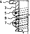
According to main embodiment of the present invention, as illustrated in fig. 1 and 2, container 1 comprises the cap 10 of a body 3 and a gastight closing body 3.
Volume controlled ring 5 direction in the shape of a spiral is formed on the outside face of sidewall of body 3 highlightedly.Volume controlled ring 5 has semi-circular cross-section, and its inside is provided with hollow passage 6.One coil spring 7 has predetermined elastic force usually, and it is accommodated in this hollow passage 6.
Therefore, when shrinking body 3 in vertical direction, the spiral raceway groove between each circle volume controlled ring 5 is folded, and makes the capacity of body 3 diminish.But under normal condition, the elastic force of coil spring 7 is applied on the body 3, therefore keeps body 3 to be in the state of expansion in vertical direction.
The process of holding thing in container 1 of the present invention is as follows.At first, the user places some things in body 3, and cap 10 is placed on the body 3.Then, the user is installed in locking ring 11 on the locking projection 4 and cap 10 is locked on the body 3.When the inventory in the container 1 during less than the capacity of body 3, the user with body 3 to pressing down to shrink body 3.By such operation, the capacity of body 3 be reduced to container 1 in the amount of content suitable.
When shrinking body 3 in this way, deflate from container 1 inside by the air valve 13 that is arranged on the cap 10, therefore realize the gas tight seal of container 1.Therefore the capacity of container 1 can control to the suitable minimum constructive height that need hold some things.In addition, container 1 can be with content, as food or beverage, fresh-keepingly reaches the quite a long time at the gas tight seal state.
When needs took out content from container 1, the user depressed air valve 13, made inrush of air in the atmosphere in container 1.When inrush of air was in container 1, body 3 vertically flexibly expanded owing to the elastic force of coil spring 7.When body 3 fully expands and return to its original-shape, take off cap 10 from body 3 after, content is taken out from container 1.
Therefore,, flexible body 3 is designed to compressible, is used to control the capacity of container 1 according to the present invention.When needs reduced the capacity of body 3, the user directly depresses body 3 so that its contraction.But when needs returned to its original-shape with body 3, the user utilized air valve 13 that the air in the atmosphere is flow in the body 3 by air valve 13, therefore was easy to make body 3 to expand, and did not need manually to make its expansion.Therefore the capacity of control body 3 is very easy to.Usually, body 3 keeps its original-shape, and promptly the shape of Peng Zhanging when therefore in container 1 some things being housed, be easy to remove the dirt in folding raceway groove, so sanitary condition is fine.And by using air valve 13, Food ﹠ Drink can keep considerable time under negative pressure state in the container 1 of controlled capacity freshly.
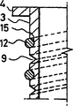
According to another embodiment of the present invention, as shown in Figure 3A, compressible slot 9 is to form spirally between the outside face of the sidewall of body 3, each circle at volume controlled ring 5, and is cut into V-shaped section.Compressible slot 9 forms along the spiral raceway groove to the bottom from the top of body 3.Therefore, when depressing body 3, body 3 is folded along compressible slot 9.Therefore, body 3 can be folded with very little power, so make the user can easily fold body 3.
In the above embodiment of the present invention, a coil spring 7 is placed in the hollow passageway 6 of volume controlled ring 5.But shown in Fig. 3 B, container 1 can be designed to only have hollow passageway 6, and does not have coil spring 7.In the case, be similar to the above-mentioned embodiment that is provided with coil spring 7,, only just body 3 can be shunk and expand into its original-shape by guiding air admission air tight seal body 3 because volume controlled ring 5 is used as a coil spring.
And, shown in Fig. 3 c, container 1 can be designed to have solid ring 5, rather than hollow passage 6, different with the embodiment shown in Fig. 3 B.According to another embodiment of the present invention, shown in Fig. 3 D, a seat groove 15 forms spirally around the sidewall of body 3, and receives a coil spring 12 therein, is used to allow body 3 to shrink and elastic expansion, therefore container 1 is made easily.
Industrial applicibility
As mentioned above, the invention provides a kind of container, it has a cap that is provided with an air valve, thereby Be convenient to control the capacity of container, be easy to clean and keep the fresh time that reaches than length of F﹠B.
Claims (5)
1. container comprises:
One flexible body has a cylindrical interior and free shrink and expansion in the axial direction; With
Form the volume controlled ring of spring, be formed on spiral form from bottom to the top of vessel on the surface of sidewall of described body, and have predetermined spring force to allow described vessel pucker ﹠ bloat in the axial direction;
The lid that is used for the described vessel oral area of capping;
Air valve, it keeps the sealing state of container in the normal state, and allows air exhaustion when described vessel shrinks, and allows air to flow into or discharge under pressed state.
2. according to the container of claim 1, wherein said volume controlled ring comprises:
A hollow passage is along the inside formation of described ring; With
A coil spring is contained in the hollow passageway, and for described body provides elasticity, so that allow the body pucker ﹠ bloat.
3. according to the container of claim 1, spiral raceway groove of formation was formed with the compressible slot around described body sidewall spirally between wherein each enclosed along described volume controlled ring.
4. according to the container of claim 1, wherein said volume controlled ring is a solid torus.
5. according to the container of claim 3, wherein the spiral compressible slot has V-shaped section.
Applications Claiming Priority (2)
| Application Number | Priority Date | Filing Date | Title |
|---|---|---|---|
| KR10-2000-0067565A KR100373458B1 (en) | 2000-11-14 | 2000-11-14 | container |
| KR67565/2000 | 2000-11-14 |
Publications (2)
| Publication Number | Publication Date |
|---|---|
| CN1398238A CN1398238A (en) | 2003-02-19 |
| CN1201976C true CN1201976C (en) | 2005-05-18 |
Family
ID=36782370
Family Applications (1)
| Application Number | Title | Priority Date | Filing Date |
|---|---|---|---|
| CNB018023061A Expired - Fee Related CN1201976C (en) | 2000-11-14 | 2001-11-13 | Container |
Country Status (13)
| Country | Link |
|---|---|
| US (1) | US6702143B2 (en) |
| EP (1) | EP1334032B1 (en) |
| JP (1) | JP3742795B2 (en) |
| KR (1) | KR100373458B1 (en) |
| CN (1) | CN1201976C (en) |
| AT (1) | ATE333416T1 (en) |
| BR (1) | BR0107070A (en) |
| DE (1) | DE60121612T2 (en) |
| DK (1) | DK1334032T3 (en) |
| ES (1) | ES2269491T3 (en) |
| HK (1) | HK1057735A1 (en) |
| PT (1) | PT1334032E (en) |
| WO (1) | WO2002040356A2 (en) |
Families Citing this family (43)
| Publication number | Priority date | Publication date | Assignee | Title |
|---|---|---|---|---|
| KR100501805B1 (en) * | 2001-12-28 | 2005-07-20 | 고려알파라인(주) | vacuum cover for function adjusting high and low |
| DE20215506U1 (en) * | 2002-05-18 | 2003-01-02 | Sommer Ira | Vessel for liquid, pasty and / or solid substances |
| WO2005016438A1 (en) * | 2003-07-17 | 2005-02-24 | Garry Tsaur | Retractable packaging |
| US7086549B2 (en) * | 2004-01-16 | 2006-08-08 | Illinois Tool Works Inc. | Fluid supply assembly |
| US7165732B2 (en) | 2004-01-16 | 2007-01-23 | Illinois Tool Works Inc. | Adapter assembly for a fluid supply assembly |
| US7665672B2 (en) | 2004-01-16 | 2010-02-23 | Illinois Tool Works Inc. | Antistatic paint cup |
| US7380680B2 (en) * | 2004-01-16 | 2008-06-03 | Illinois Tool Works Inc. | Fluid supply assembly |
| US20050258271A1 (en) * | 2004-05-18 | 2005-11-24 | Kosmyna Michael J | Disposable paint cup |
| US7766250B2 (en) | 2004-06-01 | 2010-08-03 | Illinois Tool Works Inc. | Antistatic paint cup |
| US7757972B2 (en) | 2004-06-03 | 2010-07-20 | Illinois Tool Works Inc. | Conversion adapter for a fluid supply assembly |
| US7353964B2 (en) * | 2004-06-10 | 2008-04-08 | Illinois Tool Works Inc. | Fluid supply assembly |
| US20060151520A1 (en) * | 2004-10-15 | 2006-07-13 | Kuei-Tang Chang | Cup holder |
| KR101245668B1 (en) * | 2005-01-31 | 2013-03-20 | 일리노이즈 툴 워크스 인코포레이티드 | Fluid supply assembly with measuring guide and method of measuring fluid components in the fluid supply assembly |
| US7458480B2 (en) * | 2005-05-23 | 2008-12-02 | Thuan Thien Nguyen | Disposable baby diaper container |
| US7390011B1 (en) | 2006-08-01 | 2008-06-24 | Kheam Hem | Space saver |
| DE102006047786A1 (en) * | 2006-10-06 | 2008-04-17 | Universität Rostock | Lightweight construction container i.e. bag or hose, for storing e.g. milk, has compressible and expandable spring unit extending between base unit and cover unit, and supporting receptacle in expanded condition |
| US20080110892A1 (en) * | 2006-10-18 | 2008-05-15 | House John L | Bubble top and extender for hopper |
| WO2009041800A1 (en) * | 2007-09-28 | 2009-04-02 | Lozano Escarcega Roberto Javie | Compressible flexible container |
| US20100038360A1 (en) * | 2008-08-18 | 2010-02-18 | Mcdonnell Scott | Collapsible canister for preventing animals from retrieving contents therefrom when the canister is in a non-collapsed configuration |
| EP2396234A1 (en) * | 2009-02-10 | 2011-12-21 | Ugo Nevi | Folding disposable glasses |
| US9498570B2 (en) | 2010-10-25 | 2016-11-22 | Bayer Healthcare Llc | Bladder syringe fluid delivery system |
| US10046106B2 (en) | 2010-10-25 | 2018-08-14 | Bayer Healthcare Llc | Bladder syringe fluid delivery system |
| CN102530351A (en) * | 2010-12-23 | 2012-07-04 | 苏州智泽电动工具有限公司 | Foldable water bucket |
| US8469225B2 (en) * | 2011-01-18 | 2013-06-25 | Silipint, Inc. | Semi-rigid beverage receptacle |
| WO2012174133A2 (en) * | 2011-06-14 | 2012-12-20 | Russell Jon Greenberg | Twistable and collapsible container for dispensing measured dosages of liquid |
| US8763829B2 (en) * | 2011-07-22 | 2014-07-01 | Craig Allen Madaus | Collapsible container for holding liquids or objects |
| US9237795B2 (en) | 2011-12-06 | 2016-01-19 | John Rey Hollis | Collapsible beverage cup |
| US9180252B2 (en) | 2012-04-20 | 2015-11-10 | Bayer Medical Care Inc. | Bellows syringe fluid delivery system |
| EP2810669B1 (en) * | 2013-06-03 | 2016-04-20 | Dentsply IH AB | Cylindrical collapsible container |
| JP6752774B2 (en) | 2014-04-25 | 2020-09-09 | バイエル・ヘルスケア・エルエルシーBayer HealthCare LLC | Syringe with rolling diaphragm |
| CN204363161U (en) * | 2014-08-08 | 2015-06-03 | 罗小波 | Flexible storage bottle |
| WO2016090162A1 (en) | 2014-12-04 | 2016-06-09 | Hollis John Rey | Collapsible receptacle |
| TWI621454B (en) | 2015-04-24 | 2018-04-21 | 拜耳保健公司 | Syringe with rolling diaphragm |
| US10390644B1 (en) * | 2016-02-23 | 2019-08-27 | Grisha Lachinian | Accordion sleeve for a beverage container |
| AR109649A1 (en) | 2016-09-16 | 2019-01-09 | Bayer Healthcare Llc | PRESSURE SHIRT WITH SYRINGE RETAINING ELEMENT |
| US11207462B2 (en) | 2016-10-17 | 2021-12-28 | Bayer Healthcare Llc | Fluid injector with syringe engagement mechanism |
| CA3040480C (en) | 2016-10-17 | 2024-01-23 | Bayer Healthcare Llc | Fluid injector with syringe engagement mechanism |
| DK3681561T3 (en) | 2017-09-13 | 2022-01-24 | Bayer Healthcare Llc | MOVABLE SPRAYER CAP FOR SEPARATE FILLING AND FEEDING |
| USD898301S1 (en) * | 2018-05-15 | 2020-10-06 | Meili Peng | Feeder for birds |
| US11172754B2 (en) | 2019-03-06 | 2021-11-16 | Design Fold Llc | Collapsible vessel |
| CN114502214A (en) | 2019-09-10 | 2022-05-13 | 拜耳医药保健有限公司 | Pressure jacket and syringe retention features for angiographic fluid injectors |
| AU2021224642A1 (en) | 2020-02-21 | 2022-09-15 | Bayer Healthcare Llc | Fluid path connectors for medical fluid delivery |
| BR112022023295A2 (en) | 2020-06-18 | 2023-01-17 | Bayer Healthcare Llc | IN-LINE AIR BUBBLE SUSPENSION APPARATUS FOR INJECTOR FLUID PATHWAY ANGIOGRAPHY |
Family Cites Families (16)
| Publication number | Priority date | Publication date | Assignee | Title |
|---|---|---|---|---|
| US533781A (en) * | 1895-02-05 | Windmill | ||
| US2780378A (en) * | 1953-11-13 | 1957-02-05 | Romano Mose | Collapsible container |
| US3083877A (en) * | 1960-10-25 | 1963-04-02 | Moulded Products Australasia L | Collapsible container with corrugations to facilitate the collapse of its walls |
| US3557788A (en) * | 1968-03-08 | 1971-01-26 | Betty J Swartz | Disposable syringe |
| FR2654413B1 (en) * | 1989-11-10 | 1992-02-21 | Poggi Paul | EXPANDABLE RIGID CONTAINER. |
| GB2262081A (en) * | 1991-12-06 | 1993-06-09 | Tsao Ye Ming | Contaminant-proof collapsible container |
| US5370250A (en) * | 1992-01-21 | 1994-12-06 | Gilbert; Neil Y. | Collapsible container |
| US5333761A (en) * | 1992-03-16 | 1994-08-02 | Ballard Medical Products | Collapsible bottle |
| US5209372A (en) * | 1992-04-08 | 1993-05-11 | Norwood Peter M | Collapsible spiral container |
| WO1995027522A1 (en) | 1994-04-12 | 1995-10-19 | Tsukada Medical Research Co., Ltd. | Accordion container for chemical |
| EP0733557B1 (en) | 1994-10-11 | 2001-01-17 | MAZDA, Masayosi | Bellows-shape container |
| US6105815A (en) | 1996-12-11 | 2000-08-22 | Mazda; Masayosi | Contraction-controlled bellows container |
| IT1296207B1 (en) | 1997-11-26 | 1999-06-11 | Daniela Monica Caterin Ferraro | FOOD CONTAINER. |
| US5921466A (en) | 1998-11-13 | 1999-07-13 | Arvco Container Corporation | Stackable, foldable food container |
| US6305546B1 (en) | 1999-05-14 | 2001-10-23 | Edward S. Robbins, III | Food storage containers |
| US6554149B2 (en) * | 2001-07-19 | 2003-04-29 | Aquapore Moisture Systems | Collapsible container with durable bottom shell |
-
2000
- 2000-11-14 KR KR10-2000-0067565A patent/KR100373458B1/en not_active IP Right Cessation
-
2001
- 2001-11-13 EP EP01987611A patent/EP1334032B1/en not_active Expired - Lifetime
- 2001-11-13 PT PT01987611T patent/PT1334032E/en unknown
- 2001-11-13 JP JP2002542694A patent/JP3742795B2/en not_active Expired - Fee Related
- 2001-11-13 DE DE60121612T patent/DE60121612T2/en not_active Expired - Lifetime
- 2001-11-13 CN CNB018023061A patent/CN1201976C/en not_active Expired - Fee Related
- 2001-11-13 WO PCT/KR2001/001933 patent/WO2002040356A2/en active IP Right Grant
- 2001-11-13 AT AT01987611T patent/ATE333416T1/en not_active IP Right Cessation
- 2001-11-13 BR BR0107070-3A patent/BR0107070A/en active Search and Examination
- 2001-11-13 US US10/110,255 patent/US6702143B2/en not_active Expired - Fee Related
- 2001-11-13 ES ES01987611T patent/ES2269491T3/en not_active Expired - Lifetime
- 2001-11-13 DK DK01987611T patent/DK1334032T3/en active
-
2004
- 2004-01-28 HK HK04100567A patent/HK1057735A1/en not_active IP Right Cessation
Also Published As
| Publication number | Publication date |
|---|---|
| ATE333416T1 (en) | 2006-08-15 |
| EP1334032A2 (en) | 2003-08-13 |
| CN1398238A (en) | 2003-02-19 |
| DE60121612D1 (en) | 2006-08-31 |
| KR20020037581A (en) | 2002-05-22 |
| WO2002040356A2 (en) | 2002-05-23 |
| JP3742795B2 (en) | 2006-02-08 |
| WO2002040356A3 (en) | 2002-07-25 |
| DK1334032T3 (en) | 2006-11-20 |
| DE60121612T2 (en) | 2007-07-05 |
| US6702143B2 (en) | 2004-03-09 |
| EP1334032B1 (en) | 2006-07-19 |
| PT1334032E (en) | 2006-12-29 |
| KR100373458B1 (en) | 2003-02-25 |
| ES2269491T3 (en) | 2007-04-01 |
| HK1057735A1 (en) | 2004-04-16 |
| BR0107070A (en) | 2002-09-17 |
| US20030066838A1 (en) | 2003-04-10 |
| JP2004513851A (en) | 2004-05-13 |
Similar Documents
| Publication | Publication Date | Title |
|---|---|---|
| CN1201976C (en) | Container | |
| RU2246431C2 (en) | Disposable bottle with walls compressing without shape recover | |
| JP4016248B2 (en) | Container capable of maintaining a reduced length direction and method for reducing the same | |
| US5310068A (en) | Disposable collapsible beverage bottle | |
| US4790361A (en) | Collapsible carbonated beverage container | |
| RU2198122C2 (en) | Packing container valve (versions) | |
| CN1255306C (en) | Bottle plug with pressure indicator | |
| CN1039694C (en) | Reusable re-collapsible container and resealable cap | |
| JP4698118B2 (en) | Linerless closure with pressure seal retention | |
| GB2068914A (en) | Side seal closure | |
| US4491219A (en) | Container for two-component systems | |
| CN1055665C (en) | Structure for can with discharge uper opening | |
| CN1340326A (en) | Container key for beverage | |
| WO2011055152A1 (en) | Foldable flexible bottle | |
| WO2019141973A1 (en) | A container and a closure for a container | |
| US20070007163A1 (en) | Container and a lock therefor | |
| GB2319238A (en) | Collapsible container | |
| KR200241870Y1 (en) | Liquid containing bottle capable of easy volume reduction | |
| KR200215422Y1 (en) | Retractable Liquid Bottle | |
| JPH09142479A (en) | Container whose space part can be shrunk and kept in shrunk state | |
| JPH11180428A (en) | Synthetic resin container | |
| KR200218548Y1 (en) | Stainless steel container | |
| KR100239952B1 (en) | A folding vessel | |
| CN112429366A (en) | Protective bottle shell | |
| JPH04128235U (en) | Container with variable volume |
Legal Events
| Date | Code | Title | Description |
|---|---|---|---|
| C06 | Publication | ||
| PB01 | Publication | ||
| C10 | Entry into substantive examination | ||
| SE01 | Entry into force of request for substantive examination | ||
| C14 | Grant of patent or utility model | ||
| GR01 | Patent grant | ||
| C17 | Cessation of patent right | ||
| CF01 | Termination of patent right due to non-payment of annual fee |
Granted publication date: 20050518 Termination date: 20111113 |