CN1193339C - Keyobard music instrument for producing tone and hammer sensor for stimulating physical parameter of hammer - Google Patents
Keyobard music instrument for producing tone and hammer sensor for stimulating physical parameter of hammer Download PDFInfo
- Publication number
- CN1193339C CN1193339C CNB011451750A CN01145175A CN1193339C CN 1193339 C CN1193339 C CN 1193339C CN B011451750 A CNB011451750 A CN B011451750A CN 01145175 A CN01145175 A CN 01145175A CN 1193339 C CN1193339 C CN 1193339C
- Authority
- CN
- China
- Prior art keywords
- hammer
- music data
- sensor
- key
- light
- Prior art date
- Legal status (The legal status is an assumption and is not a legal conclusion. Google has not performed a legal analysis and makes no representation as to the accuracy of the status listed.)
- Expired - Fee Related
Links
- 230000004936 stimulating effect Effects 0.000 title 1
- 230000003287 optical effect Effects 0.000 claims abstract description 15
- 230000033001 locomotion Effects 0.000 claims description 57
- 230000000875 corresponding effect Effects 0.000 claims description 44
- 230000007246 mechanism Effects 0.000 claims description 24
- 238000000034 method Methods 0.000 claims description 18
- 230000008569 process Effects 0.000 claims description 15
- 230000008859 change Effects 0.000 claims description 14
- 230000003068 static effect Effects 0.000 claims description 10
- 230000009471 action Effects 0.000 claims description 8
- 230000005236 sound signal Effects 0.000 claims description 7
- 230000007704 transition Effects 0.000 claims description 4
- 238000002834 transmittance Methods 0.000 claims description 2
- 230000007613 environmental effect Effects 0.000 abstract 1
- 230000005622 photoelectricity Effects 0.000 description 30
- 239000013307 optical fiber Substances 0.000 description 10
- 230000000994 depressogenic effect Effects 0.000 description 8
- 238000001514 detection method Methods 0.000 description 6
- 230000005355 Hall effect Effects 0.000 description 5
- 230000000977 initiatory effect Effects 0.000 description 5
- 238000003860 storage Methods 0.000 description 5
- 230000005540 biological transmission Effects 0.000 description 4
- 238000004891 communication Methods 0.000 description 4
- 239000000463 material Substances 0.000 description 4
- 230000008901 benefit Effects 0.000 description 3
- 230000000903 blocking effect Effects 0.000 description 3
- 230000000881 depressing effect Effects 0.000 description 3
- 238000010586 diagram Methods 0.000 description 3
- 229920003002 synthetic resin Polymers 0.000 description 3
- 239000000057 synthetic resin Substances 0.000 description 3
- XEEYBQQBJWHFJM-UHFFFAOYSA-N Iron Chemical compound [Fe] XEEYBQQBJWHFJM-UHFFFAOYSA-N 0.000 description 2
- 239000006096 absorbing agent Substances 0.000 description 2
- 230000001133 acceleration Effects 0.000 description 2
- 239000004411 aluminium Substances 0.000 description 2
- XAGFODPZIPBFFR-UHFFFAOYSA-N aluminium Chemical compound [Al] XAGFODPZIPBFFR-UHFFFAOYSA-N 0.000 description 2
- 229910052782 aluminium Inorganic materials 0.000 description 2
- 238000004364 calculation method Methods 0.000 description 2
- 238000005520 cutting process Methods 0.000 description 2
- 238000013461 design Methods 0.000 description 2
- 238000007599 discharging Methods 0.000 description 2
- 230000003116 impacting effect Effects 0.000 description 2
- 238000005259 measurement Methods 0.000 description 2
- NIXOWILDQLNWCW-UHFFFAOYSA-M Acrylate Chemical compound [O-]C(=O)C=C NIXOWILDQLNWCW-UHFFFAOYSA-M 0.000 description 1
- 239000004820 Pressure-sensitive adhesive Substances 0.000 description 1
- 230000032683 aging Effects 0.000 description 1
- 238000004458 analytical method Methods 0.000 description 1
- 238000003491 array Methods 0.000 description 1
- 230000000712 assembly Effects 0.000 description 1
- 238000000429 assembly Methods 0.000 description 1
- 230000015572 biosynthetic process Effects 0.000 description 1
- 238000006243 chemical reaction Methods 0.000 description 1
- HGAZMNJKRQFZKS-UHFFFAOYSA-N chloroethene;ethenyl acetate Chemical compound ClC=C.CC(=O)OC=C HGAZMNJKRQFZKS-UHFFFAOYSA-N 0.000 description 1
- 238000012937 correction Methods 0.000 description 1
- 230000008878 coupling Effects 0.000 description 1
- 238000010168 coupling process Methods 0.000 description 1
- 238000005859 coupling reaction Methods 0.000 description 1
- 238000013016 damping Methods 0.000 description 1
- 230000008451 emotion Effects 0.000 description 1
- 238000005516 engineering process Methods 0.000 description 1
- 238000005530 etching Methods 0.000 description 1
- 239000004615 ingredient Substances 0.000 description 1
- 239000013067 intermediate product Substances 0.000 description 1
- 229910052742 iron Inorganic materials 0.000 description 1
- 230000001788 irregular Effects 0.000 description 1
- 238000004519 manufacturing process Methods 0.000 description 1
- 230000010287 polarization Effects 0.000 description 1
- 230000000644 propagated effect Effects 0.000 description 1
- 238000004080 punching Methods 0.000 description 1
- 230000000717 retained effect Effects 0.000 description 1
- 239000004065 semiconductor Substances 0.000 description 1
- 238000007493 shaping process Methods 0.000 description 1
- 230000011664 signaling Effects 0.000 description 1
- 238000004088 simulation Methods 0.000 description 1
- 239000000758 substrate Substances 0.000 description 1
- 238000013268 sustained release Methods 0.000 description 1
- 239000012730 sustained-release form Substances 0.000 description 1
- KKEYFWRCBNTPAC-UHFFFAOYSA-L terephthalate(2-) Chemical compound [O-]C(=O)C1=CC=C(C([O-])=O)C=C1 KKEYFWRCBNTPAC-UHFFFAOYSA-L 0.000 description 1
- 239000012780 transparent material Substances 0.000 description 1
- 230000003245 working effect Effects 0.000 description 1
Images


Classifications
-
- G—PHYSICS
- G10—MUSICAL INSTRUMENTS; ACOUSTICS
- G10C—PIANOS, HARPSICHORDS, SPINETS OR SIMILAR STRINGED MUSICAL INSTRUMENTS WITH ONE OR MORE KEYBOARDS
- G10C3/00—Details or accessories
- G10C3/16—Actions
- G10C3/18—Hammers
-
- G—PHYSICS
- G10—MUSICAL INSTRUMENTS; ACOUSTICS
- G10F—AUTOMATIC MUSICAL INSTRUMENTS
- G10F1/00—Automatic musical instruments
- G10F1/02—Pianofortes with keyboard
-
- G—PHYSICS
- G01—MEASURING; TESTING
- G01D—MEASURING NOT SPECIALLY ADAPTED FOR A SPECIFIC VARIABLE; ARRANGEMENTS FOR MEASURING TWO OR MORE VARIABLES NOT COVERED IN A SINGLE OTHER SUBCLASS; TARIFF METERING APPARATUS; MEASURING OR TESTING NOT OTHERWISE PROVIDED FOR
- G01D5/00—Mechanical means for transferring the output of a sensing member; Means for converting the output of a sensing member to another variable where the form or nature of the sensing member does not constrain the means for converting; Transducers not specially adapted for a specific variable
- G01D5/26—Mechanical means for transferring the output of a sensing member; Means for converting the output of a sensing member to another variable where the form or nature of the sensing member does not constrain the means for converting; Transducers not specially adapted for a specific variable characterised by optical transfer means, i.e. using infrared, visible, or ultraviolet light
- G01D5/32—Mechanical means for transferring the output of a sensing member; Means for converting the output of a sensing member to another variable where the form or nature of the sensing member does not constrain the means for converting; Transducers not specially adapted for a specific variable characterised by optical transfer means, i.e. using infrared, visible, or ultraviolet light with attenuation or whole or partial obturation of beams of light
- G01D5/34—Mechanical means for transferring the output of a sensing member; Means for converting the output of a sensing member to another variable where the form or nature of the sensing member does not constrain the means for converting; Transducers not specially adapted for a specific variable characterised by optical transfer means, i.e. using infrared, visible, or ultraviolet light with attenuation or whole or partial obturation of beams of light the beams of light being detected by photocells
- G01D5/347—Mechanical means for transferring the output of a sensing member; Means for converting the output of a sensing member to another variable where the form or nature of the sensing member does not constrain the means for converting; Transducers not specially adapted for a specific variable characterised by optical transfer means, i.e. using infrared, visible, or ultraviolet light with attenuation or whole or partial obturation of beams of light the beams of light being detected by photocells using displacement encoding scales
- G01D5/34707—Scales; Discs, e.g. fixation, fabrication, compensation
- G01D5/34715—Scale reading or illumination devices
-
- G—PHYSICS
- G01—MEASURING; TESTING
- G01D—MEASURING NOT SPECIALLY ADAPTED FOR A SPECIFIC VARIABLE; ARRANGEMENTS FOR MEASURING TWO OR MORE VARIABLES NOT COVERED IN A SINGLE OTHER SUBCLASS; TARIFF METERING APPARATUS; MEASURING OR TESTING NOT OTHERWISE PROVIDED FOR
- G01D5/00—Mechanical means for transferring the output of a sensing member; Means for converting the output of a sensing member to another variable where the form or nature of the sensing member does not constrain the means for converting; Transducers not specially adapted for a specific variable
- G01D5/26—Mechanical means for transferring the output of a sensing member; Means for converting the output of a sensing member to another variable where the form or nature of the sensing member does not constrain the means for converting; Transducers not specially adapted for a specific variable characterised by optical transfer means, i.e. using infrared, visible, or ultraviolet light
- G01D5/32—Mechanical means for transferring the output of a sensing member; Means for converting the output of a sensing member to another variable where the form or nature of the sensing member does not constrain the means for converting; Transducers not specially adapted for a specific variable characterised by optical transfer means, i.e. using infrared, visible, or ultraviolet light with attenuation or whole or partial obturation of beams of light
- G01D5/34—Mechanical means for transferring the output of a sensing member; Means for converting the output of a sensing member to another variable where the form or nature of the sensing member does not constrain the means for converting; Transducers not specially adapted for a specific variable characterised by optical transfer means, i.e. using infrared, visible, or ultraviolet light with attenuation or whole or partial obturation of beams of light the beams of light being detected by photocells
- G01D5/347—Mechanical means for transferring the output of a sensing member; Means for converting the output of a sensing member to another variable where the form or nature of the sensing member does not constrain the means for converting; Transducers not specially adapted for a specific variable characterised by optical transfer means, i.e. using infrared, visible, or ultraviolet light with attenuation or whole or partial obturation of beams of light the beams of light being detected by photocells using displacement encoding scales
- G01D5/34776—Absolute encoders with analogue or digital scales
-
- G—PHYSICS
- G10—MUSICAL INSTRUMENTS; ACOUSTICS
- G10G—REPRESENTATION OF MUSIC; RECORDING MUSIC IN NOTATION FORM; ACCESSORIES FOR MUSIC OR MUSICAL INSTRUMENTS NOT OTHERWISE PROVIDED FOR, e.g. SUPPORTS
- G10G3/00—Recording music in notation form, e.g. recording the mechanical operation of a musical instrument
- G10G3/04—Recording music in notation form, e.g. recording the mechanical operation of a musical instrument using electrical means
Abstract
A hammer sensor includes a photo-filter plate movable together with a hammer assembly and having a base plate fixed to the hammer shank and an arc pattern formed on the base plate and different in transparency from the base plate, a photo radiating element radiating a light beam toward the arc pattern and a photo detecting element disposed on the optical path of the light beam for converting the amount of transmitted light to an electric signal, wherein the photo-filter plate converts the rotational angle of the hammer assembly to the amount of light incident on the photo detecting element, and makes the photo radiating element and the photo detecting element stationary so that a suitable photo-shield case prevents the photo elements from environmental light.
Description
Technical field
The present invention relates to a kind of keyboard instrument, more particularly, relate to a kind of keyboard instrument that is equipped with hammer, for example, an automatic playing piano and a mute piano, and be applied to one of them hammer sensor.
Background technology
The automatic playing piano is a combined keyboard instrument that constitutes based on acoustic piano, one row arranges key sensor by the key drive unit and of solenoid control and key is provided with accordingly, and an electronic control system is linked to the key drive unit array and the key sensor array of solenoid control, when a player plays a tune on key, Mo Jian and Bai Jian are depressed respectively by the player, and the key sensor that is associated is to the action situation of electronic control system report key.Electronic control system is determined the black/white key and the d/d black/white key that are depressed, and definite black/white key duration of being depressed and discharging, and, the speed of electronic control system calculation key.These music data information are stored with one group of music data code, so that reset.
When the user instruction electronic control system went to reproduce the performance situation, electronic control system was read the music data message segment.Control system is with the key transmission output drive signal of the cycle identical with original performance to solenoid control, and the key transmission of solenoid coil control drives relevant black/white key, and need not to do any playing on key.Thereby, the performance that automatic playing piano record is initial, and reproduce initial performance and need not on key, to do any playing.
Mute piano is another kind of synthetic keyboard instrument, and row's key sensor is provided with corresponding to key, and an electronics tone generation system is linked on the key sensor array, and a hammer detent is variable between free position and stop position.When the hammer detent was transformed free position, the hammer detent was moved out of the track of hammer.The player impacts string by playing optionally with hammer on key, just produced the tone of acoustic piano by vibrations of strings.If the player changes to stop position to the hammer detent, the hammer detent just is moved in the track of hammer.Even the player plays a tone on key, hammer also can be rebounded by the hammer detent before impacting string, and the hammer of any acoustic piano accent all can not produce from string.Yet key sensor is monitored relevant black/white key, and reports the motion conditions of key to electronics tone generation system.Electronics tone generation system is determined the black/white key pressed and the black/white key of release, and the speed of definite key.Electronics tone generation system produces an electronic signal of representing the tone that will generate, and the electronics tone is produced by an audio system.
Therefore, key sensor all is indispensable in automatic playing piano and mute piano.When a player presses the black/white key to the final position from rest position simply, key sensor is accurately reported the motion conditions of key to Electronic Control/electronics tone generation system, be equal to original tone fully and reproduce tone/electronics tone, this is because the hammer speed that relevant hammer is matched with the speed with key is taken turns to drive.Yet playing is not that motion by single key constitutes usually.When a black/white key can repeatedly be pressed by the player, other black/white key may be in returning the way in final position.In this case, the motion of key does not cause the hammer speed motion that hammer matches with the motion with key.As a result, the tone of reproduction/electronics tone is generated with the volume different with the piano tone of original piano tone/generate.Therefore, key sensor almost can not reflect the motion conditions of complicated key.
In order accurately to determine the motion of hammer, suggestion directly detects the motion of hammer.One row's hammer sensor is installed in the casing of piano.The hammer sensor directly detects corresponding hammer, and reports the current location of corresponding hammer.According to these positional informations, electronic control system/electronics tone generation system is accurately determined the motion of hammer, and stores these music data information with music data code.
The present known some kinds of hammer sensors that have.First kind of hammer sensor is the combination of a shadow shield and a photoelectrical coupler.Be formed a window on the shadow shield.In addition, photoelectrical coupler produces a plurality of light beams.Shadow shield presents and has window, and shadow shield is fixed on the hammer handle, and can move with the hammer assembly thus.Such as, photoelectrical coupler is by the action bearing bracket, and the light beam of shadow shield track is passed in generation.When corresponding black and white key was depressed, actuating mechanism drove the hammer assembly and rotates, and shadow shield is along its orbiting motion.When shadow shield touches light beam, shadow shield blocking light beam.Shadow shield interdicts light beam constantly up to arriving window.Shadow shield allows light beam by window, and interdicts light beam once more.Electronic control system/electronics tone generation system basis is from beginning most to interdict the speed that light to light passes the duration calculating hammer of window.Shadow shield is suitably designed so that electronic control system/electronics tone generation system is measured the time that hammer impacts string.
Second kind of hammer sensor and is the combination of a reflected light electric coupler 500 and a reflector plate 502 as shown in Figure 1.Reflection ray coupling mechanism 500 is fixed on the static carriage 501, and penetrates a light beam to hammer assembly 503.On the other hand, reflector plate 502 is fixed on the hammer handle 504, and moves with the movement locus of hammer assembly 503 along hammer handle 504.Light beam reflection on reflector plate 502 all the time, and go back to reflecting photoelectric coupler 500.Catoptrical amount changes along with the hammer current location, and reflecting photoelectric coupler 500 is reported catoptrical amount to electronic control system/electronics tone generation system.Electronic control system/electronics tone generation system is determined the current location of hammer, and calculates the speed of hammer.When catoptrical amount reached a predetermined value, electronic control system/electronics tone generation system determined that single hammering beats the moment of string 505.
The third hammer sensor is the combination of a Hall effect element and a permanent magnet elements.Reflecting photoelectric coupler 500 is replaced by Hall effect element, and permanent magnet elements is fixed on the hammer handle 504.Magnetic field intensity changes along with the distance between Hall effect element and the permanent magnet elements, and Hall element produces electric current in the magnetic field that is caused by the permanent-magnet pieces element.The size of element current has been represented the intensity in magnetic field, thereby has represented the distance between Hall element and the permanent magnet.Electronic control system/electronics tone generation system is determined the current location of hammer according to the size of electric current, and calculates the speed of hammer, and when electric current reached a predetermined value, electronic control system/electronics tone generation system decision should impact the moment of string.Therefore, these several hammer sensors and electronic control system/electronics tone generation system cooperation, and in the process of the music data information that writes down or generate the playing procedure of representative on key, assist electronic control system/electronics tone generation system.Yet, some problems below in above-mentioned several hammer sensors, running into.
An intrinsic problem in first kind of hammer sensor is that the hammer sensor array is vulnerable to depart from entopic influence.Time decision by window impacts moment of string to electronic control system/electronics tone generation system according to light beam, this means that moment that electronic control system/electronics tone generation system decision impacts string is to be based upon the supposition photoelectrical coupler and shadow shield is to be placed on the suitable target location.If photoelectrical coupler or shadow shield have departed from the target location.Electronic Control/electronics tone generation system can not accurately determine to impact the moment of string.First kind of hammer sensor required careful assembly work, and adjust termly.
Another intrinsic problem is that detectable range is narrow in first kind of hammer sensor.Detectable range equals the edge of shadow shield and the distance between the wherein formed window, and the movement locus of hammer assembly is more much longer than detectable range.Yet the photocurrent of photoelectrical coupler is immovable outside detectable range, and electronic control system/electronics tone generation system can not obtain any positional information outside detectable range.
An intrinsic problem is the serious noise component that is superimposed upon on the electric signal of representing the hammer current location in second kind of hammer sensor.If second kind of hammer sensor is placed in the constant ecotopia of background luminance, second kind of hammer sensor will produce the electric signal of accurately representing the hammer current location.Yet natural light and/or room light can incide in the photoelectrical coupler.Unfortunately, the brightness of natural light/room light is along with the position of season and combined keyboard instrument changes.This means the brightness that the fabricator can not projected background.For this reason, noise component is serious, and makes electronic control system/electronics tone generation system determine the current location and the moment that impacts string of hammer mistakenly.
Intrinsic in the third a hammer sensor problem also is the severe noise component.This is because the residing magnetic field of Hall element had not only been produced by the permanent magnet of correspondence but also by contiguous permanent magnet generation.The hammer assembly is rotated by drive, and the magnetic field intensity of each Hall effect element is not only to change but also change along with the current location of contiguous hammer assembly along with the current location of the hammer assembly of correspondence.The influence of magnetic field of near permanent magnet element is the reason that produces noise component.
Another intrinsic problem is by a kind of approximate error component that causes in second kind and the third hammer sensor.The output voltage of photoelectrical coupler/Hall effect element changes as nonlinear curve PL1 represented (as Fig. 2 A) from the rest position to the final position.Electronic control system/electronics tone generation system is approximately linearity curve PL2 (as Fig. 2 B) to nonlinear curve PL1, and determines the current location of hammer according to linearity curve PL2.Electronic control system/electronics tone generation system is according to the data message of the data message generation music of position, and error component is retained in the music data information.
Summary of the invention
Therefore, a free-revving engine of the present invention provides a kind of keyboard instrument and accurately produces tone.
Another free-revving engine of the present invention provides a kind of hammer sensor, and it has a wide detectable range, and on behalf of the output signal aspect of hammer current location, generation accurately have good reliability.
According to an aspect of the present invention, provide the keyboard instrument that is used to produce tone, having comprised: a plurality of keys, they can arrive self-movement between the final position separately in rest position separately; A plurality of actuating mechanisms, they are connected respectively on described a plurality of key, so that the motion of key drives corresponding action mechanism; A plurality of hammers correspond respectively to described a plurality of actuating mechanism, and rotate under corresponding actuating mechanism drives; And music data generation system, it comprises: a plurality of hammer sensors, they monitor described a plurality of hammer respectively, be used to detect respectively with respect to the part physical parameter of rotating described a plurality of hammers in the plane, be used to produce the hammer signal, each comprises: photoemissive element in described a plurality of hammer sensor, it is static with respect to described part, and along launching light beam at the upwardly extending light path in the side on the plane of passing corresponding hammer, photoelectric apparatus, it is static and be arranged on the described light path with respect to described part, being used to produce the hammer signal of representing the incident light size, and converter, it can rotate with corresponding hammer, and by described light beam irradiates, being used for the change transitions of described physical parameter is the variation of incident light size; Data process subsystem, it is connected on described a plurality of hammer sensor, be used to receive described hammer signal, and analysis is changed the motion of represented hammer by the light quantity of the incident light of corresponding each described hammer, so that produce the sound signal of the tone that the motion of representative by described hammer will produce, described converter comprises: a base members, this base members has in corresponding hammer rotation process with respect to the movable surface of described light path, so that described light beam is along a described lip-deep track relative motion, and on optical characteristics different pattern, this optical characteristics influences the incident light quantity of described base members, and this pattern takes place how much and changes on the direction parallel with described track.
According to a further aspect in the invention, a kind of hammer sensor that is used to detect the physical parameter of hammer is provided, it is rotatable in a plane with respect to a part, this sensor comprises: photoemissive element, it is static with respect to described part, and along the upwardly extending light path emission light beam in the side of passing described plane; Photoelectric apparatus, it is static with respect to described part, and is arranged on the described light path, is used to produce the electric signal of representing the incident light size; Converter, it can rotate with described hammer, and by described light beam irradiates, being used for the change transitions of described physical parameter is the variation of described incident light quantity; Described converter comprises: a base members, this base members has in corresponding hammer rotation process with respect to the movable surface of described light path, so that described light beam is along a described lip-deep track relative motion, and on optical characteristics different pattern, this optical characteristics influences the incident light quantity of described base members, and this pattern takes place how much and changes on the direction parallel with described track.
Description of drawings
The characteristic of this keyboard instrument and hammer sensor and advantage will be by being easier to understanding, wherein in conjunction with following the description of the drawings:
Fig. 1 is the side view of hammer sensor that the current hammer of the detection position of prior art is shown;
Fig. 2 A is the curve that current hammer position and output voltage relation are shown;
Fig. 2 B illustrates the curve that concerns through between hammer position after the linear-apporximation and the output voltage;
Fig. 3 is the synoptic diagram that illustrates according to automatic playing piano of the present invention;
Fig. 4 is the skeleton view that is illustrated in the hammer sensor of decomposing state;
Fig. 5 is the front view that the filter that forms a hammer sensor part is shown;
Fig. 6 A and 6B are the front views that the filter that is in different angles is shown;
Fig. 7 is the floor map that the layout of hammer sensor is shown;
Fig. 8 illustrates the synoptic diagram that is connected to the photoelectric subassembly on the combination photoelectric device;
Fig. 9 A is the skeleton view that the photoelectric subassembly that separates with shell is shown;
Fig. 9 B is the sectional view of I-I intercepting along the line, and the chlamydate photoelectric subassembly of assembling is shown;
Figure 10 be illustrate from substrate pull down one row photoelectric subassembly skeleton view;
Figure 11 is the planimetric map that the sensor bracket that is supported by a hammer handle flange guide rail (shank flange rail) is shown;
Figure 12 is the sectional view of J-J intercepting along the line, and the hammer sensor that is contained in the big grand piano is shown;
Figure 13 is the skeleton view that sensor stand is shown;
Figure 14 is the synoptic diagram that hammer assembly movement locus is shown;
Figure 15 illustrates according to the structure side view for the key of practising using of the present invention;
Figure 16 is the structure side view that illustrates according to a mute piano of the present invention; And
Figure 17 is the structural representation that another kind of photoelectric device is shown.
Embodiment
First kind of embodiment
Keyboard instrument
Referring to Fig. 3, one is embodied automatic playing piano of the present invention and mainly comprises an acoustic piano and an electronic control system.In this case, big grand piano is used as acoustic piano.Yet upright piano also can be used as the automatic playing piano.In the following description, " front " this speech is meant the end near the player, and promptly that is sitting in the people's who plays piano on the stool a end, and on the other side is " back "." vertically ", this speech was meant the direction that is parallel to the line between anterior locations and the back location, and " laterally " is meant perpendicular to direction longitudinally.
Acoustic piano comprise a key or one row black and white key 1, hammer assembly 2, actuating mechanism 3, organize string 4 and staccato device 6 more.Black and white key 1 is arranged with well-known style, and laterally is placed on the key bed 7.When a player pressed each black/white key anterior, the front portion of key sank, and the black/white key rotates around a balance beam 7a.
String 4 is arranged by the musical note of scale, and quilt is also promptly corresponding with black/white key 1 with the 2 corresponding placements of hammer assembly.When black/white key 1 was in rest position, hammer assembly 2 separated with relevant group string 4, and hammer assembly 2 begins freely to rotate after breaking away from corresponding action mechanism 3, and impacts corresponding group string 4.Should vibrate to produce tone by group string 4 then.On the other hand, hammer assembly 2 is rebounded by string 4, and returns rest position.Hammer assembly 2 is received lightly by a backhaul clamping device (back check) 3a, and reaches rest position after the black/white key 1 that is pressed discharges.
Staccato device 6 is provided with for string 4 respectively.Each staccato device 6 leaves certain distance by depressing black/white key 1 with the string 4 of respective sets, and touches string 4 after discharging black/white key 1.When staccato device 6 left this group string 4, string 4 was allowed to vibration.Yet when staccato device 6 was come to corresponding string 4, string 4 can not vibrate.
Electronic control system is divided into two subsystems.One of them subsystem is used to reset, and is called as " automatic playing subsystem " hereinafter.Another subsystem produces representative and play the music data code of situation on key, and is called as " music data generation subsystem " hereinafter.
The automatic playing subsystem is linked on a sound-track engraving apparatus or the communication system, and music data code is imported in the automatic playing subsystem, is used for rotating the black/white key selectively and need not to play.The automatic playing subsystem comprises the key actuator 14 of a data processor 10, motion controller 11, servo controller 12, electronics tone maker 13 and row's solenoid control, the key actuator 14 of solenoid control is installed in below the rear portion of black/white key 1 respectively, and be equipped with built-in speed pickup, music data code is input to data processor 10 continuously, and data processor 10 instruction motion controllers 11 stretch out or regain the piston of the key actuator 14 that solenoid controls by servo controller 12.When a drive signal is input to the key actuator of solenoid control from servo controller 12, the key actuator 14 of solenoid control upwards stretches out piston from solenoid, and built-in speed pickup is used for reporting current piston speed to feedback signal of servo controller 12 feedbacks.
Particularly, music data code is divided into two classes, the music data information of first kind music data code storage representative incident, such as note key encode that incident/note stops the black/white key that incident, representative will be rotated, velocity of rotation appear, with pitch of the tone that produces or the like.The performance that the storage representative of the second class music data code takes place from incident begins the control data information of time of being experienced.
Music data code of hypothesis represents that the moment that incident takes place appears in corresponding note now, and data processor 10 is according to the definite black/white key 1 that will rotate of key encode, and the movement locus of definite black/white key 1.Time t that data processor 10 notice motion controllers 11 begin to rotate and initial velocity Vr etc., promptly coordinate (t, Vr).Motion controller 11 is determined a series of coordinates on track, and provides target velocity to servo controller 12 continuously.Servo controller 12 is determined the size of drive signal, and provides drive signal to the key actuator of corresponding solenoid control.By this drive signal, solenoid produces magnetic field, and upwards releases piston.Piston promotes the rear portion of corresponding black/white key 1.The black/white key 1 that is so promoted by piston separates staccato device 6 from string 4, and black/white key 1 is rotated around balance guide rail 7a.Black/white key 1 starting actuating mechanism 3, and hammer 2 is driven by evasive movement mechanism 3 and does freely to rotate.Hammer 2 impacts string 4, and string 4 produces tone.Therefore, the automatic playing subsystem is played a piece of music and be need not to play on key.
When the user selects electronics tone maker 13, data processor 10 transmits music data code with suitable sequential to electronics tone maker, and electronics tone maker 13 produces the sound signal of a simulation from music data code.Electronics tone maker 13 from a suitable sound source such as giving off the electronics tone consistent a loudspeaker and/or the earphone with the piano tone.The automatic playing subsystem can a kind of ensemble of performance between the key actuator 14 of solenoid control and electronics tone maker 13.
Music data generates subsystem and comprises row's hammer sensor 21, a data processor 28 and a music data code maker 29.Hammer sensor 21 is monitored each hammer assembly 2 respectively, and produces the hammer signal of representing the current physical parameter of hammer assembly 2 in its movement locus.In this case, hammer sensor 21 is determined an angle between rest positions and the current hammer position, and the angle or the current hammer position of the corresponding hammer assembly 2 of hammer signal description thus.The hammer signal is sent to a data input port of data processor 28, and changes digital signal into by a suitable analog-digital converter (not shown).Data processor 28 is the scan data input terminal mouth termly, and stores the hammer data of all hammer assemblies in a dynamic storage (wording memory) (not shown).Therefore, data processor 28 repeating data scanning at a certain time interval and data acquisition are so that be stored in the dynamic storage about a series of hammer data of each black/white key 1.Music data code maker 29 is analyzed the hammer data of representing hammer to move in its movement locus.Music data code maker 29 is determined the concrete black/white keys of depressing 1, and determines to begin to the termination of each incident constantly from performance.Music data code maker 29 is according to the change calculations speed of angle.Therefore, music data code maker 29 obtains music data information according to the hammer data, and the music data information stores in one group of music data code.Music data code is stored in (not shown) in the suitable information storage medium.In addition, music data code by the public's or privately owned communication network be sent to another musical instrument or a data storer.
The hammer sensor
Referring to Fig. 4, hammer sensor 21 is provided with explicitly with hammer assembly 2.Hammer assembly 2 has the felt (manner felt) of a shaping at the front end of hammer handle 2a, and hammer handle 2a is attached on the hammer handle flange 2b rotationally by a pin 71.This sells the axis that a rotation is provided for hammer handle 2a, and hammer handle 2a is driven around pin 71 rotations.
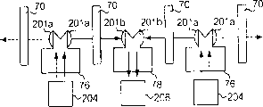
Each hammer sensor 21 is similar each other.Each hammer sensor 21 comprises a photoelectricity filter 70, a photoemission mouth 201a and a photoelectricity receiving port 201b.Filter 70 is made an arc patterns usually, and has a central shaft.Filter 70 is fixed on the side surface of hammer handle 2a as follows, that is, the rotation axis of hammer handle 2a and central shaft are in line.In this case, filter 70 adheres to the side surface of sound handle 2a by a kind of pressure sensitive adhesive tape of coated on both sides.The light-receiving mouth of the photoemission mouth 201a of each hammer sensor 21 and adjacent hammer sensor 21 becomes one.The photoemission mouth 201a of adjacent hammer sensor and photoelectricity receiving port 201b and prism 75 assemblings form an electrooptical device, and directed relative direction.Therefore, the photoemission mouth 201a of the photoelectricity receiving port 202b of each hammer sensor 21 and adjacent hammer sensor 21 is integral, and the light emission port 201a and the prism 75 of photoelectricity receiving port 202b, adjacent hammer sensor 21 combine formation with next electrooptical device.The light path of photoemission mouth 201a becomes a line with the light path of photoelectricity receiving port 201b.Filter 70 is alternately arranged with electrooptical device, and the electrooptical device light path that is arranged in light emission/photoelectricity receiving port 201a/201b departs from the central shaft of filter 70.
Fig. 6 A has shown the filter 70 that is fixed on the hammer handle 2a.The lower surface of the radial surface of extension 70s and hammer handle 2a in one plane, and the termination surface of the radial surface of another extension 70t and hammer handle 2a is in one plane.Angle 70u aligns with the line 2ar that intersect on lower surface and termination surface.The center line 71a of filter 70 and the center line of pin 71 overlap, and those center lines are all perpendicular to the center line of hammer handle 2a.Therefore, filter 70 is designed to be easy to be assembled on the hammer handle 2a.When hammer assembly 2 is in rest position, the light path 80s of photoemission mouth 201a as shown in Figure 6A pass arc patterns 73.Reference numeral " S " refers to a dummy line between the center of center line 71a and light path 80s.
Suppose that the player has depressed relevant black/white key 1.Actuating mechanism 3 causes that hammer assembly 2 rotates, and hammer handle 2a changes the position, from 2a to 2a ', as shown in Figure 6A.Angle between the 2a to 2a ' is represented with θ.Light path between photoemission mouth 201a and the photoelectricity receiving port 201b locates to pass filter 70 at 80s '.Angle between 80s and the 80s ' equals the angle between 2a and the 2a ', and also represents with θ.
As mentioned above, opaque section increases in the counterclockwise direction with the ratio of hyalomere branch.This means that at photoelectricity receiving port 201b light intensity be to reduce in the counterclockwise direction.In other words, turn to from rest position the process of impact point at hammer handle 2a, the light intensity at photoelectricity receiving port 201b place little by little reduces.The damping capacity of unit angle designs arbitrarily.For this reason, angle θ can be determined by calculating the different light intensity degree.
Electrooptical device and filter 70 are staggered, and electrooptical device comprises photoemission mouth 201a, photoelectricity receiving port 201b and a prism 75, shown in Fig. 7 and 8.On photoemission mouth 201a and the photoelectricity receiving port 201b convex lens are housed respectively.Prism 75 is to be made by transparent synthetic resin, such as acrylate, and has a cutting between a pair of plane parallel to each other.Photoemission mouth 201a is fixed on this on one in the plane, and photoelectricity receiving port 201b is fixed on another plane.Cutting is limited by inclined surface, and light beam reflects at inclined surface respectively, so that change light path, as shown by arrows.Prism 75 is to be made of a pair of locating slot 203 and an aperture, and it be will be described hereinafter.
Electrooptical device is connected on the combination photoelectric element 201, and this combination photoelectric element has a photoemissive element and an optical detection device, and optical fiber 100 transmission ray between combination photoelectric element 201 and electrooptical device.Optical fiber 100 is inserted in the aperture, and the front end of optical fiber 100 arrives the bottom surface of aperture.Combination photoelectric element 202 alternately sends light and light signal is converted to the hammer signal, resembles merotype when a kind of.In this case, combination photoelectric element 202 is launched light from the element 202 of low order end to the element 202 of high order end thereupon, and as shown in Figure 7, light beam incides on the combination photoelectric element in the left side respectively.
As mentioned above, the photoelectricity receiving port 201b of the photoemission mouth 201a of electrooptical device and adjacent electrooptical device is paired, and sets up the light path by filter 70 between them.The a branch of light of hypothesis incides the photoelectricity receiving port 201b or the convex lens of electrooptical device as shown in Figure 8 in distributing to a time slot of light-current conversion now, and incident light is by the reflection of the dip plane on right side, and reflected light is converged to the terminal 100a of optical fiber 100.Light is transferred to combination photoelectric element 202 by optical fiber 100.Photodetector in the combination photoelectric element 202 is converted to photocurrent to light, and suitable converter produces the hammer signal from photocurrent.
Distribute in the photoemissive time slot at the next one, the photoemissive element emission light in the combination photoelectric element 202, light is propagated by another terminal 100b of optical fiber 100.Light is transmitted into prism 75 from terminal 100a.Light continues to advance to the dip plane, and is reflected thereon.Light is divided into two light beams, and these beam-pointing photoemission mouth 201a and photoelectricity receiving port 201b.Parallel light is transmitted into adjacent electrooptical device from photoemission mouth 201a or convex lens.
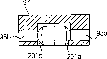
Electrooptical device and a light shielding mask 97 integrate.The opaque synthetic resin of light shielding mask 97 usefulness is made.Light shielding mask 97 may be dyed black.In light shielding mask 97, form the space of a hollow, and on the sidewall of light shielding mask 97, be formed with through hole 98a/98b.Rectangular opening 98c also is formed on the sidewall of light shielding mask 97, and another rectangular opening 98d is formed on the antetheca of light shielding mask 97.A slit (not shown) is formed on the rear wall of light shielding mask 97.Electrooptical device is arranged in the space of hollow closely, and light shielding mask 97 blocks the influence that prism 75 upper surfaces make its interference-free light, and detent 203 is exposed, because the lower surface of prism 75 is not covered by light shielding mask 97.Shown in Figure 10 is the situation that light shielding mask 97 is removed from electrooptical device.
When electrooptical device and light shielding mask 97 assemblings, optical fiber 100 is by slit, and through hole 98a/98b aims at photoelectricity emission port 201a and photoelectricity receiving port 201b respectively.For this reason, the light beam that emits from photoemission mouth 201a passes through through hole 98a directive filter 70, and incident beam arrives photoelectricity receiving port 201b by another through hole 98b.
A base plate 90 and a top board 95 are formed a sensor bracket.The electrooptical device that fits together with light shielding mask 97 is installed in (see figure 10) on the base plate 90.Base plate 90 is made such as an aluminium sheet, an iron plate or a black synthetic resin board by the opaque material manufacturing.Base plate 90 has a planar section 90a and a bossing 90b.Bossing 90b has the reverse U shape shape.Slit 91 is formed on the base plate 90 at certain intervals, and each slit 91 extends to bossing 90b from planar section 90a.Slit 91 is assigned to filter 70 respectively.When base plate 90 is fixed on the hammer handle flange guide rail 8 (seeing Figure 11) by sensor stand 99, filter 70 is set in the slit 91, and can not be subjected to the ground motion of any obstruction.Adjustment hole 93 also is set on the bossing 90b, and repeats to adjust screw and be exposed in the adjustment hole 93.
The electrooptical device that is installed on the base plate 90 is covered by top board 95.Top board 95 is made by opaque material as base plate 90.Top board 95 has two from the reclinate end 95a/95b of its remainder.The relative surface level B of planar section 90a becomes the direction of α angle to extend back from bossing 90b, and endwise skew thereafter.When top board 95 dropped on the base plate 90, fore-end 95a contacted with the upper surface of bossing 90b, and rear end part 95b contacts with the rearward end of planar section 90a.Top board 95 is fixed on the base plate 90 by a kind of suitable fixing means.Therefore, the electrooptical device of having assembled light shielding mask 97 is accommodated in the space between base plate 90 and the top board 95.
On top board 95 with certain adjustment hole 96 that is interval with.When top board 95 was fixed on the base plate 90, adjustment hole 96 was aimed at adjustment hole 93 respectively.Adjustment hole 93 and 96 allows an instrument not need to take top board 95 and base plate 90 apart from sensor stand 99 near re-adjustments screw 304 (seeing Figure 12).
By above explanation as can be known, sensor bracket 90/95 and light shielding mask 97 protection electrooptical devices are not subjected to the interference of surround lighting, thereby noise can not enter into the hammer signal.And paired detent 203 and paired location lug 92 make assembly work easier, and make photoemission mouth 201a aim at corresponding photoelectricity receiving port 201b.Therefore, see that from these viewpoints it is preferred using sensor bracket 90/95.
Following description explanation hammer sensor 21 is how to install explicitly with hammer assembly 2.Figure 11 and 12 has shown the sensor bracket 90/95 that is supported by hammer handle flange guide rail 8.String 4 is divided into 4 or 5 groups.Sensor stand 99 is linked on the hammer handle flange guide rail 8, and extend under the gap between the string group backward, in the breach of hammer assembly.Sensor bracket 90/95 is connected to the rearward end of sensor stand 99.
At first, with reference to Figure 13 sensor stand 99 is elaborated.Sensor stand 99 is divided into two part 99a and 99b.Fore-end 99a is a reverse U shape shape on section, and rear end part is the word shape of falling L on section.Fore-end 99a and rear end part 99b separate certain distance, and rear end part 99b is bent upwards with respect to fore-end 99a.A through hole 302 is formed on the fore-end 99a, and allows a screw 302a to insert wherein downwards.On the other hand, two through holes on rear end part 99b, and are allowed two screw 300a upwards to insert wherein respectively by shape.Pair of notches 99d is set on the vertical wall of fore-end 99a, and divide at a certain distance with front ends surface, this distance equals the vertical plane 8c of hammer handle flange guide rail 8 and the distance (seeing Figure 12) between the guiding rope 9 in groove that is inserted in hammer handle flange guide rail.
Guiding rope 9 is used as accurately hammer assembly 2 is positioned on the hammer handle flange guide rail 8.Hammer handle 2a is rotatably connected on the hammer handle flange 2c, and otch 2d is set on the hammer handle flange 2c.Hammer handle flange guide rail 8 is formed with a step, and vertical plane 8c and groove are separated and separate a predetermined distance with the guiding rope thus.The end face of hammer handle flange 2c and the distance between the otch 2d also are adjusted to predetermined distance.When a workman was fixed to hammer assembly 2 on the hammer handle flange guide rail 8, the workman aimed at guiding rope 9 to otch 2d, and by screw hammer handle flange 2c was fixed on the hammer handle flange guide rail 8.Therefore, guiding rope 9 is provided with for the purpose of accurately locating hammer assembly 2 on hammer handle flange guide rail 8.
So, otch 99d, vertical plane 8c and guiding rope 9 make base plate 90 be fixed on the position that is fit on the sound handle 2a, and filter 70 is set at the appropriate location of slit 91.Detent 203 and location lug 92 are suitably located electrooptical device with respect to filter 70.Therefore, the fabricator is installed to the hammer sensor in the big grand piano easily by using sensor bracket 90/95 and sensor stand 99.
The working condition of automatic playing piano
Player produces the music data code that representative is once played by the automatic playing piano, and instruction one section music of automatic playing piano performance and need not to do any playing at key.Like this, automatic playing piano selectivity is in a kind of music data code generate pattern and a kind of automatic playing pattern.In the music data code generate pattern, music data code is written into during a suitable information stores is provided with, in a semiconductor memory, disk or CD.Otherwise music data code is sent on a data memory device or another musical instrument by a public or privately owned communication line.On the other hand, one group of music data code is sent to the automatic playing piano by public/privately owned communication line or reads from information-storing device, and the tone of piano and/or electronics tone produce based on this group music data code.
Suppose that the player selects the music data generate pattern.Music data code generates subsystem and is activated, and when the player played one section melody, he or she depressed Bai Jian 1 at hypothesis, as shown in Figure 3, discharges it then.
When the player applied a power in the front portion of white key 1, its front portion sank to its final position, and the white key 1 that is depressed causes staccato device 6 and actuating mechanism 3 to start.Staccato device 6 leaves string 4, and string 4 is prepared vibration.Actuating mechanism 3 promotes hammer handle 2a, and hammer handle 2a begins to rotate.When support column touches adjusting knob, the support column rotation, and hammer assembly 2 spins off from support column.The hammer assembly is driven and freely rotates, and impacts string 4.String 4 vibrations, and produce a kind of piano tone.On string, hammer assembly 2 is rebounded by string 4, and rotates round about.Hammer assembly 2 is caught by backhaul detent 3a, and backhaul detent 3a keeps hammer assembly 2.When the player discharged the white key 1 be depressed, Bai Jian 1 turned back to rest position, and backhaul detent 3a falls down.Therefore, hammer assembly 2 returns rest position.In returning the process of rest position, staccato device 6 is touched on the string 3 once more, and staccato device 6 has absorbed the vibration of string.Then, the piano tone disappears.Hammer assembly 2 arrives rest position, and after this, Bai Jian 1 arrives rest position.The motion of hammer as shown in figure 14.
For the piano tone of resetting, require to obtain the clock data in the following moment of representative.
1. the moment T10 that white key 1 begins to move downward,
2. hammer assembly 2 moment T1 that begins to rotate,
3. hammer assembly 2 impacts the moment T2 of string 4,
4. backhaul detent 3a catches the moment T3 of hammer assembly 2,
5. backhaul detent 3a begins to return the moment T4 of rest position,
6. staccato device 6 touches the moment TD of string 4,
7. hammer assembly 2 turns back to the moment T5 of rest position, and
8. white key 1 turns back to the moment T11 of rest position.
9. the spot speed V2 after the hammer speed V1 of moment and hammer impacted before hammer impacted, and
10. the spot speed V3 after hammer discharges from backhaul detent 3a.
Music data code maker 29 needs the moment Ts1 of representative in string 4 motion processes and the clock data and the data message of representing the D1 partial-length of moment Ts2, to be used for calculating hammer speed V1.Similarly, music data code maker 29 needs to represent moment Ts3 and the clock data of Ts4 and the data message of the length of representing the D2 part in the rest position motion process, to be used for calculating hammer speed V2.Yet hammer speed V2 may be unwanted.Music data code maker 29 also needs to represent TS5 and the clock data and the data message of representative apart from d3 and part D3 length of TS6 constantly constantly.
In detail, the hammer sensor 21 that combines with white key 1 is monitored hammer assembly 2 by light beam always.When hammer assembly 2 remained on rest position, light beam 80S was by arc patterns 73 (seeing Fig. 6 A), and it is constant to incide the light quantity of photoelectricity receiving port 201b.Light quantity is in maximal value, and the level of hammer signal is minimum.When hammer assembly 2 begins to rotate, the rotation of filter 70 causes the minimizing of the beam intensity that incides photoelectricity receiving port 201b, and the hammer signal level increases.Because data processor 28 is the check data input end termly, looks at whether any hammer sensor 21 changes the level of hammer signal, music data code maker 29 is easily determined T1 constantly.
When playback piano tone, the key actuator 14 of solenoid control is being located the rear portion that begins to promote white key constantly with moment T10 is corresponding.In other words, servo controller 12 provides drive signal to the key actuator 14 of solenoid control when moment T10.Music data code maker 29 is determined the initial of key at moment T10, and it is stored in the music data code.
After moment T1, hammer assembly 2 rotates to string 4, and light beam 80s motion (seeing Fig. 6 A and 6B) on arc patterns 73 in the counterclockwise direction.The light quantity that incides photoelectricity receiving port 201b reduces gradually, and the size of hammer signal increases thus.Data processor 28 is the check data input end termly, looks at whether the size of hammer signal is still increasing.When hammer assembly 2 impacted string 4, hammer assembly 2 rebounded from it, and to back rotation.For this reason, light beam motion on arc patterns 73 along clockwise direction, and the light quantity that incides on the photoelectricity receiving port 201b increases.Thus, the size of hammer signal reduces.Then conclusion become negative, thereby music data code maker 29 has been determined the moment T2 of turning point.Music data code maker 29 determines that at moment T2 be the tone initiation event, and it is stored in the music data code.When playback, electronics tone maker 13 is producing the electronics tone corresponding to moment of T2, and data processor 10 according to time T 10 and time T 2 determine tracks (t, Vr).
In the automatic playing piano of prior art, the music data code maker is judged the initial moment T2 of tone according to the time T 10 of key sensor report, and the moment T2 that judges like this might have deviation with the initial timing of the tone of reality.On the other hand, music data code maker 29 directly moves to determine the initial situation of tone according to the hammer of hammer sensor 21 reports.This reason thus, the music data code that produces in automatic playing piano according to the present invention has accurately been described original performance.
In addition, when moment T2, turning point is the actual final position of the track of hammer assembly 2, and is actual measurement in the light quantity of final position.T1 position constantly is actual rest position, and is to determine easily in the light quantity of rest position.Even filter 70 is owing to for example be to have changed transmittance owing to polluting, as if combination photoelectric element 202 has changed the light propagation property and has changed the light emission characteristics owing to all aging and/or optical fiber 100, and music data code generates subsystem easily according in the measured value calibration level of the size of termination/rest position light and the relation between angle/hammer position.
Music data code maker 29 calculates hammer speed V1 with following method.The remote point and the difference d1 between the string of dotted portion D1 and D1 part are stored in the music data code maker 29.The length of dotted portion D1 and difference d1 are such as being respectively 5 millimeters and 0.5 millimeter.Music data code maker 29 calculates all end points of D1 part, and determines time T s1 and Ts2 by the actual value of more end-on hammer signal and the expectation value of hammer signal thus.Then, hammer speed V1 is drawn by following formula:
V1=D1/(Ts2-Ts1)
Under the situation that needs hammer speed V2, music data code maker 29 similarly according to the length computation of D2 part it, wherein D2 part and turning point be at a distance of d2, and Ts3/Ts4 is two end points in the D2 part constantly.Therefore, music data code maker 29 is determined the time T s1/Ts2 and the Ts3/Ts4 of each end points of D1/D2 portion according to the time T 2 of actual measurement.For this reason, even distortion appears in string and/or motion appears in hammer sensor 21 by accident, music data code maker 29 is accurately determined the speed of hammer.The volume of piano tone is to be directly proportional with the speed V1 of hammer.In addition, it is linear change that arc patterns 73 is designed to make the level of hammer signal, and for this reason, music data code maker 29 is accurately determined the volume of piano tone.Volume or speed are stored in the music data code.
Music data code maker 29 is also checked storer, looks at whether hammer assembly 2 restarts to back rotation.When music data code maker 29 was found 2 beginnings of hammer assembly to back rotation, music data code maker 29 was determined T4 constantly.
After determining moment T4, music data code maker 29 is determined Ts5 and Ts6 constantly.Length apart from d3 and part D3 is known, and the music data code maker 29 usefulness method same with determining moment Ts1 and moment Ts2 determined Ts5 and Ts6 constantly.Then, music data code maker 29 divided by the time period between time T s5 and the time T s6, and is determined hammer speed V3 to the length of part D3.
When the player discharged white key 1, Bai Jian 1 began to return rest position, and allowed the staccato device to fall.Staccato device 6 contacts with string 4 at moment TD, and absorbs the vibration of string 4.In this case, the length of part D3 is adjusted to and covers staccato device 6 drops.When hammer assembly 2 arrived the remote location of D3 part, music data code maker 29 hypothesis staccato devices 6 touched string 4, and judge that time T D equals time T s6.Music data code maker 29 determines that the tone vanishing state appears at time T D, and it is stored in the music data code.
In the performance of a reality, player is the speed of sustained release key 1 delicately, to express his or her emotion.When the player allowed the black/white key return at leisure, staccato device 6 also was to fall at leisure, and the vibration of string 4 is extended.In detail, suppose that a string 4 produces a drummy speech.If the player discharges black/white key 1 at leisure, the string 4 of vibration just began to touch staccato device 6 before staccato device 6 reaches string 4.When the player kept black/white key 1 and keeps resolving mixer 6 thus, vibration was continued, but amplitude reduces gradually.Therefore, the player can prolong tone by keep the black/white key in returning the process of rest position.In this case, time T D changes according to hammer speed V3.The length of part D3 may change according to key speed V3, so that make that the attenuation initiation of piano tone is identical with the actual tone decay of playing.
After the release, Bai Jian 1 returns to rest position, and reaches rest position at moment T5.White key 1 is in the static position stop motion, and that the hammer signal is kept level is constant.Music data code maker 29 check storeies look at that whether the hammer signal level is at a definite time-preserving.If answer is sure, music data code maker 29 judges that white key 1 arrives rest position in time T 5.
At last, music data code maker 29 judgement time T11.Music data code maker 29 has the value of one group of D12 part, and selects one of them value according to hammer speed V3.Music data code maker 29 is according to length, hammer speed V3 and moment T5 T11 computing time of part D12.Music data code maker 29 decision bond motion End Events occur in T11 constantly, and it is stored in the music data code.
Simply the front portion of black/white key 1 is pressed down to final position from rest position a player, and discharges then in its process, hammer assembly 2 is along curvilinear motion shown in Figure 14.In performance the player only to depress all black/white keys simply from the rest position to the final position be rarely found.In the performance of a reality, the player discharges some keys before arriving rest position, and by the key of depressing other.If the player repeats a key 15 times/second or more, hammer is tending towards departing from curve shown in Figure 14, and this is because instantaneous the appearing between vibration footing and the driving shaft screw in gap.If the player repeatedly presses key with irregular time intervals, the motion of reproducing hammer is a difficulty.For this reason.Music data code maker 29 is revised music data information so that make the motion of reproduction hammer become possibility.Making under the situation of automatic playing piano according to upright piano, if the player repeats a key 7 times/second or more, it is necessary making correction.Yet it is responsive that 13 pairs of electronics tone makers are represented the music data code that repeats at a high speed.Music data code maker 29 is not revised music data information, and produces the music data code of representing the actual music data message.
As mentioned above, hammer sensor 21 according to the present invention is monitored corresponding hammer assembly 2 on whole movement locus, and provides to data processor 28 and to represent the hammer signal of representing the hammer current location in the track.Music data code maker 29 is chosen music data information from clock data, and determines T1-T5 and speed constantly, is used for storing music data code.Therefore, music data code maker 29 determines that accurately key motion initiation event, tone initiation event, tone termination incident and key motion stop the volume of the tone of incident and generation.
Especially, arc patterns 73 is at random determined.This means that the fabricator can design the hammer position and incide relation between the light quantity of photoelectricity receiving port.When the fabricator is designed to linearity with its relation.Data processor 28 is determined the physical location of hammer by using linear relationship, and any being similar to all is unwanted.Therefore, any error component can not enter into clock data, and initial performance situation is reproduced from music data code faithfully.
Music data generates subsystem can also comprise row's key sensor, and these key sensors identify with Reference numeral 21a at accompanying drawing 3.In this case, key sensor 21a detects the key motion End Event, and determines the moment of player's release key according to the signal that key sensor 21a transmits to data processor 28.Key sensor array 21a can with 21 concurrent workings of hammer sensor array.In this case, if the hammer sensor can not detect the tone initiation event.The signal deciding that 29 bases of music data code maker are provided by key sensor impacts the time of string 4.
Second embodiment
Referring to Figure 15, be an embodiment key of making according to upright piano that exercise is used of the present invention.Black/white key 40 and actuating mechanism 41 are same with those upright pianos, and hammer assembly and string are replaced by 43 and vibration absorbers 44 of dumb sound hammer.When a trainee played a tone on black/white key 41, actuating mechanism 42 was started.And dumb sound hammer 43 is driven and rotates.Dumb sound hammer 43 rebounds on vibration absorber 44, and any tone does not all have to produce.
The key that exercise is used also comprises an electronics tone generation system.Electronics tone generation system comprises row's hammer sensor 45, a controller 46 and an audio system 47.Hammer sensor 45 is the same with hammer sensor 21, and monitors dumb sound key 43 respectively.Hammer sensor 45 produces the hammer position signalling of representing the current location of dumb sound hammer in movement locus, and the hammer signal is delivered to controller 46.Controller 46 and audio system 47 are corresponding to data processor 28, music data code maker and electronics tone maker 13.Controller 46 produces music data code, and a sound signal that produces from music data code is sent to audio system 47, with generating the electronics tone.
But hammer sensor 45 has the sensing range wideer than the angular range of hammer handle, so that the code of the music data that controller 46 produces is accurately represented the motion of hammer.This key has embodied another advantage of automatic playing piano.
The 3rd embodiment
Figure 16 illustrates one and has embodied mute piano of the present invention.Mute piano is an intermediate product between an acoustic piano and electronics tone maker system, and a hammer detent 51 is installed on hammer assembly 2 arrays.The ingredient of acoustic piano is labelled with the Reference numeral of appropriate section in the automatic playing piano, and electronics tone generation system comprises hammer sensor 21, data processor 28, music data code maker 29 and electronics tone maker 13.These system units 21,28,29 are the same with those in appropriate sections that music data code generates in the subsystem with 13 the course of work.For this reason, acoustic piano and electronics tone generation system are not further described hereinafter.
Mute piano has realized whole advantages of automatic playing piano.
In first to the 3rd embodiment, photoemission mouth 201a, optical fiber 100 and combination photoelectric element 202 constitute photoemissive element as a whole, and photoelectricity receiving port 201b, optical fiber 100 and combination photoelectric element 202 constitute photoelectric apparatus as a whole, filter 70 is made of arc patterns 73, as a converter.Hammer handle flange guide rail 8 is corresponding with a part.
Though certain embodiments of the present invention is demonstrated and describes, apparent for those skilled in the art, can carry out various changes and improvements in the situation of not leaving the spirit and scope of the present invention.
Physical parameter can be hammer speed or acceleration.
Filter can be made of the opaque material with a band slit pattern.Opaque material is an aluminium, and a plurality of arcuate slots forms slit pattern.Slit pattern can form by a kind of etching.Otherwise slit pattern can form by a kind of punching press.Filter can be realized by a pair of polarization plates.
Music data code maker 29 may be stored negative value in the time period between time T 1 and time T 10.In this case, music data code maker 29 is selected a negative value according to hammer speed V1, and it and T1 addition constantly.
Music data code maker 29 can be stored one group of value about a time period Δ t (seeing Figure 14), so that directly according to hammer speed V1/V3 judgement time T10/ time T 11.
Any pattern can both be as the pattern of filter, as long as this pattern is according to hammer position change light quantity.Dot pattern, grid-like pattern and grid pattern all are the examples of adoptable pattern.
Relation between hammer position and the light quantity can be non-linear.In the above-described embodiment, transmission is only incided the photoelectricity receiving port.Yet the light of reflection can be incided the photoelectricity receiving port.
Electrooptical device can alternately be attached on photoemissive element 204 and the photodetector 206, as shown in figure 17.
Paired light emission/photodetector can be set at photoemission mouth 201a and photoelectricity receiving port 201b position in line on.
Not only physical parameter, such as the hammer position, hammer speed and hammer acceleration also can be detected and/or be calculated to be used for analyzing the motion of hammer.Hammer speed can not only calculated on an interval.In this case, the value of hammer speed is asked average so that eliminate measuring error from timing data.
Certainly, position data can be analyzed as other time kind data.Some clock data can be left in the basket in producing music data code.In other words, even the behaviour of hammer sensor surveys the angle variation range of scope greater than the hammer assembly, the hammer sensor is monitored corresponding hammer assembly to produce the hammer signal in predetermined section.
Claims (9)
1. keyboard instrument that is used to produce tone comprises:
A plurality of keys (1; 41), they can arrive self-movement between the final position separately in rest position separately;
A plurality of actuating mechanisms (3; 42), they are connected respectively to described a plurality of key (1; 41) on, so that the motion of key drives corresponding action mechanism;
A plurality of hammers (2; 43), correspond respectively to described a plurality of actuating mechanism (3; 42), and under corresponding actuating mechanism drives rotate; And
A music data generation system, it comprises:
A plurality of hammer sensors (21; 45), they monitor described a plurality of hammer (2 respectively; 43), be used for detecting respectively, be used to produce the hammer signal, described a plurality of hammer sensors (21 with respect to a part (8) physical parameter of rotating described a plurality of hammers in the plane; 45) each comprises in:
Photoemissive element (201a/100/202; 201a/100/204), it is static with respect to described part (8), and along launching light beam at the upwardly extending light path in the side on the plane of passing corresponding hammer,
Photoelectric apparatus (201b/100/202; 201b/100/206), it is static and be arranged on the described light path with respect to described part (8), being used to produce the hammer signal of representing the incident light size, and
Converter (70), its can with corresponding hammer (2; 43) rotate together, and by described light beam irradiates, being used for the change transitions of described physical parameter is the variation of incident light size; With
Data process subsystem (21/28/29/13; 46), it is connected to described a plurality of hammer sensor (21; 45) on, be used to receive described hammer signal, and analyze by corresponding each described hammer (2; The light quantity of incident light 43) changes the motion of represented hammer, so that produce the sound signal of the tone that the motion of representative by described hammer will produce, it is characterized in that:
Described converter (70) comprises a base members, and this base members has in corresponding hammer rotation process with respect to the movable surface of described light path, so that described light beam is along a described lip-deep track relative motion, and
Different pattern (73) on optical characteristics, this optical characteristics influences the incident light quantity of described base members, and this pattern takes place how much and changes on the direction parallel with described track.
2. keyboard instrument as claimed in claim 1 is characterized in that described optical characteristics is meant the transmittance to described light beam.
3. keyboard instrument as claimed in claim 1 is characterized in that, described base members on penetrability greater than described pattern.
4. keyboard instrument as claimed in claim 1, it is characterized in that, described pattern is by a plurality of arc (73-1, ..., 73-m) realize, these arcs have the corresponding center of circle of rotation axis (71a) with described corresponding hammer, and change the ratio of described pattern (73) area and the exposed area on described surface along with the rotational angle of described corresponding hammer.
5. keyboard instrument as claimed in claim 1 is characterized in that, described pattern (73) makes described hammer signal along with the rotational angle of described corresponding hammer changes linearly.
6. keyboard instrument as claimed in claim 1 is characterized in that, described music data generation system also comprises a light shield part (90/95/97), and it protects the influence of the interference-free light of described hammer sensor (219).
7. keyboard instrument as claimed in claim 1, also comprise the string (4) that polycomponent is not impacted by described a plurality of hammers (2), be used for producing described tone, and a plurality of staccato devices (6), they are connected with described a plurality of keys (1) respectively, are used for allowing selectively described many group strings (4) to produce vibration in the key action back of correspondence.
8. keyboard instrument as claimed in claim 7 also comprises an automatic playing subsystem, and this subsystem comprises the actuator (14) of a plurality of solenoid controls, and these actuators move described a plurality of keys respectively; And a data processing unit (10/11/12), the music data code of the described tone that it indicates to be generated from the output of described data process subsystem is used for to the solenoid actuator energy supply relevant with the string that can produce described tone.
9. one kind is used to detect hammer (2; The hammer sensor of physical parameter 43), it is rotatable in a plane with respect to a part (8), and this sensor comprises:
Photoemissive element (201a/100/202; 201a/100/204), it is static with respect to described part (8), and along the upwardly extending light path emission light beam in the side of passing described plane;
Photoelectric apparatus (201b/100/202; 201b/100/206), it is static with respect to described part (8), and is arranged on the described light path, is used to produce the electric signal of representing the incident light size;
Converter (70), it can rotate with described hammer, and by described light beam irradiates, being used for the change transitions of described physical parameter is the variation of described incident light quantity;
Described converter (70) comprises a base members, and this base members has in corresponding hammer rotation process with respect to the movable surface of described light path, so that described light beam is along a described lip-deep track relative motion, and
Different pattern (73) on optical characteristics, this optical characteristics influences the incident light quantity of described base members, and this pattern takes place how much and changes on the direction parallel with described track.
Applications Claiming Priority (3)
| Application Number | Priority Date | Filing Date | Title |
|---|---|---|---|
| JP2000351192A JP4595193B2 (en) | 2000-11-17 | 2000-11-17 | Hammer detection device |
| JP351192/00 | 2000-11-17 | ||
| JP351192/2000 | 2000-11-17 |
Publications (2)
| Publication Number | Publication Date |
|---|---|
| CN1365097A CN1365097A (en) | 2002-08-21 |
| CN1193339C true CN1193339C (en) | 2005-03-16 |
Family
ID=18824295
Family Applications (1)
| Application Number | Title | Priority Date | Filing Date |
|---|---|---|---|
| CNB011451750A Expired - Fee Related CN1193339C (en) | 2000-11-17 | 2001-11-17 | Keyobard music instrument for producing tone and hammer sensor for stimulating physical parameter of hammer |
Country Status (5)
| Country | Link |
|---|---|
| US (2) | US6515213B2 (en) |
| EP (1) | EP1207515A3 (en) |
| JP (1) | JP4595193B2 (en) |
| KR (1) | KR100435211B1 (en) |
| CN (1) | CN1193339C (en) |
Families Citing this family (33)
| Publication number | Priority date | Publication date | Assignee | Title |
|---|---|---|---|---|
| JP4595193B2 (en) * | 2000-11-17 | 2010-12-08 | ヤマハ株式会社 | Hammer detection device |
| JP4374803B2 (en) * | 2001-06-26 | 2009-12-02 | ヤマハ株式会社 | Optical sensor |
| JP3820936B2 (en) * | 2001-07-31 | 2006-09-13 | ヤマハ株式会社 | Key sensor, key sensor detection board and keyboard instrument |
| JP3743363B2 (en) * | 2001-12-13 | 2006-02-08 | ヤマハ株式会社 | Silencer for keyboard instruments |
| JP4013251B2 (en) * | 2003-02-21 | 2007-11-28 | ヤマハ株式会社 | Processing equipment for mounting automatic performance equipment |
| JP4079064B2 (en) * | 2003-09-25 | 2008-04-23 | ヤマハ株式会社 | Rotating motion detection device |
| CN100561572C (en) * | 2003-12-05 | 2009-11-18 | 张文革 | Piano wireless remote control automatic playing system |
| JP4626241B2 (en) * | 2003-12-24 | 2011-02-02 | ヤマハ株式会社 | A method for generating a musical instrument and pronunciation instruction information and a program for executing the method on a computer. |
| US7285718B2 (en) * | 2003-12-22 | 2007-10-23 | Yamaha Corporation | Keyboard musical instrument and other-type musical instrument, and method for generating tone-generation instructing information |
| JP4218552B2 (en) * | 2004-03-04 | 2009-02-04 | ヤマハ株式会社 | Keyboard instrument |
| EP1575026A2 (en) * | 2004-03-12 | 2005-09-14 | Yamaha Corporation | Automatic player musical instrument, for exactly controlling the keys |
| JP4487617B2 (en) * | 2004-04-14 | 2010-06-23 | ヤマハ株式会社 | Keyboard instrument sensor frame mounting structure |
| JP4193752B2 (en) * | 2004-05-07 | 2008-12-10 | ヤマハ株式会社 | Automatic piano |
| JP4552227B2 (en) | 2005-01-24 | 2010-09-29 | ヤマハ株式会社 | Position detection device |
| JP4444131B2 (en) * | 2005-01-26 | 2010-03-31 | 株式会社河合楽器製作所 | Keyboard instrument speed detection device |
| JP4501725B2 (en) * | 2005-03-04 | 2010-07-14 | ヤマハ株式会社 | Keyboard instrument |
| JP4822782B2 (en) * | 2005-09-15 | 2011-11-24 | 株式会社河合楽器製作所 | Keyboard instrument touch detection device |
| JP2008268362A (en) * | 2007-04-17 | 2008-11-06 | Kawai Musical Instr Mfg Co Ltd | Electronic keyboard instrument and its processing method |
| JP2009098582A (en) * | 2007-10-19 | 2009-05-07 | Yamaha Corp | Drive unit |
| JP5209287B2 (en) * | 2007-12-13 | 2013-06-12 | ローランド株式会社 | Electronic musical instrument operation position detection device |
| JP5298534B2 (en) * | 2008-01-08 | 2013-09-25 | ヤマハ株式会社 | Action mechanism |
| US8686275B1 (en) * | 2008-01-15 | 2014-04-01 | Wayne Lee Stahnke | Pedal actuator with nonlinear sensor |
| WO2009108437A1 (en) * | 2008-02-27 | 2009-09-03 | Steinway Musical Instruments, Inc. | Pianos playable in acoustic and silent modes |
| US20090282962A1 (en) * | 2008-05-13 | 2009-11-19 | Steinway Musical Instruments, Inc. | Piano With Key Movement Detection System |
| US8148620B2 (en) * | 2009-04-24 | 2012-04-03 | Steinway Musical Instruments, Inc. | Hammer stoppers and use thereof in pianos playable in acoustic and silent modes |
| US8541673B2 (en) | 2009-04-24 | 2013-09-24 | Steinway Musical Instruments, Inc. | Hammer stoppers for pianos having acoustic and silent modes |
| JP5641285B2 (en) * | 2010-03-18 | 2014-12-17 | カシオ計算機株式会社 | Electronic keyboard instrument |
| JP5104928B2 (en) * | 2010-09-06 | 2012-12-19 | ヤマハ株式会社 | Performance information playback device |
| US8519252B2 (en) * | 2011-03-16 | 2013-08-27 | Waleed Sami Haddad | Optoelectronic pickup for musical instruments |
| US9383274B2 (en) * | 2011-10-31 | 2016-07-05 | Nsk Ltd. | Torque detection apparatus and electric power steering apparatus |
| US9047851B2 (en) | 2012-09-19 | 2015-06-02 | Light4Sound | Optoelectronic pickup for musical instruments |
| US20150122112A1 (en) * | 2013-11-03 | 2015-05-07 | Miselu Inc. | Sensing key press activation |
| CN106205578A (en) * | 2016-08-29 | 2016-12-07 | 四川文化艺术学院 | MIDI steering wheel ten thousand phonic wheel |
Family Cites Families (18)
| Publication number | Priority date | Publication date | Assignee | Title |
|---|---|---|---|---|
| JPS62153999A (en) * | 1985-12-27 | 1987-07-08 | ローランド株式会社 | Key-on switch for keyboard unit of electronic musical apparatus |
| US5237123A (en) | 1991-02-06 | 1993-08-17 | Laurence G. Broadmoore | Velocity, position and direction-tracking sensor for moving components of musical instruments |
| JPH06138870A (en) | 1992-10-29 | 1994-05-20 | Kawai Musical Instr Mfg Co Ltd | Key displacement detector for instrument keyboard |
| JPH06149234A (en) * | 1992-11-04 | 1994-05-27 | Kawai Musical Instr Mfg Co Ltd | Hammer action detecting device of keyboard musical instrument |
| JPH06149233A (en) * | 1992-11-05 | 1994-05-27 | Kawai Musical Instr Mfg Co Ltd | Method for adjusting key displacement detecting device of keyboard musical instrument |
| JP3684610B2 (en) * | 1994-08-01 | 2005-08-17 | ヤマハ株式会社 | Keyboard information output device |
| JP3552366B2 (en) * | 1995-06-09 | 2004-08-11 | ヤマハ株式会社 | Music control device |
| JP3552374B2 (en) * | 1995-11-30 | 2004-08-11 | ヤマハ株式会社 | Signal output device and optical sensor |
| JPH10161648A (en) * | 1996-12-04 | 1998-06-19 | Yamaha Corp | Keying-string hammering characteristic conforming device, drive signal-string hammering characteristic conforming device, and keyed instrument |
| JP3716104B2 (en) * | 1998-06-30 | 2005-11-16 | 京セラ株式会社 | Optical module |
| JP3887968B2 (en) * | 1998-09-18 | 2007-02-28 | ヤマハ株式会社 | Keyboard instrument and key speed judgment device |
| JP3900712B2 (en) * | 1998-10-23 | 2007-04-04 | ヤマハ株式会社 | Keyboard instrument sensor calibration apparatus and sensor calibration method |
| JP3887978B2 (en) * | 1998-12-25 | 2007-02-28 | ヤマハ株式会社 | Performance support device, performance support method, and recording medium recording performance support program |
| US6384305B1 (en) * | 1999-05-19 | 2002-05-07 | Overture Music Systems, Inc. | Method and apparatus for sensing key movement in a musical keyboard |
| JP4069557B2 (en) * | 1999-12-16 | 2008-04-02 | ヤマハ株式会社 | Hammer detection device and performance information acquisition device |
| JP4595193B2 (en) * | 2000-11-17 | 2010-12-08 | ヤマハ株式会社 | Hammer detection device |
| JP4221896B2 (en) * | 2000-11-30 | 2009-02-12 | ヤマハ株式会社 | Optical fiber sensor |
| JP4374803B2 (en) * | 2001-06-26 | 2009-12-02 | ヤマハ株式会社 | Optical sensor |
-
2000
- 2000-11-17 JP JP2000351192A patent/JP4595193B2/en not_active Expired - Fee Related
-
2001
- 2001-11-14 US US10/002,262 patent/US6515213B2/en not_active Expired - Lifetime
- 2001-11-16 EP EP01127230A patent/EP1207515A3/en not_active Withdrawn
- 2001-11-17 KR KR10-2001-0071614A patent/KR100435211B1/en not_active IP Right Cessation
- 2001-11-17 CN CNB011451750A patent/CN1193339C/en not_active Expired - Fee Related
-
2002
- 2002-11-13 US US10/293,181 patent/US6940005B2/en not_active Expired - Lifetime
Also Published As
| Publication number | Publication date |
|---|---|
| EP1207515A3 (en) | 2011-05-04 |
| US20030070526A1 (en) | 2003-04-17 |
| KR100435211B1 (en) | 2004-06-09 |
| JP2002156967A (en) | 2002-05-31 |
| US6515213B2 (en) | 2003-02-04 |
| CN1365097A (en) | 2002-08-21 |
| JP4595193B2 (en) | 2010-12-08 |
| US6940005B2 (en) | 2005-09-06 |
| EP1207515A2 (en) | 2002-05-22 |
| US20020059862A1 (en) | 2002-05-23 |
| KR20020038560A (en) | 2002-05-23 |
Similar Documents
| Publication | Publication Date | Title |
|---|---|---|
| CN1193339C (en) | Keyobard music instrument for producing tone and hammer sensor for stimulating physical parameter of hammer | |
| US10950137B2 (en) | Smart piano system | |
| US7642448B2 (en) | Optical transducer system for monitoring movable parts, optical modulator and musical instrument using the same | |
| US6403872B2 (en) | Keyboard musical instrument faithfully reproducing original performance without complicated tuning and music data generating system incorporated therein | |
| US6359207B1 (en) | Position transducer system with built-in calibrator for moving object, method for accurately determining position of moving object and keyboard musical instrument equipped with the position transducer system | |
| CN101271638B (en) | Musical instrument with electronic proof system, electric system and computer program | |
| CN1667696A (en) | Automatic player musical instrument, automatic player used therein and method for exactly controlling keys | |
| CN1818663A (en) | Speed detecting apparatus for keybord musical instrument | |
| CN1811904A (en) | Self-calibrating transducer system and musical instrument equipped with the same | |
| CN101064100A (en) | Automatic player musical instrument, testing system incorporated therein and method for specifying half pedal point | |
| CN1746968A (en) | High-fidelity automatic player musical instrument, automatic player used therein and method employed therein | |
| CN1637849A (en) | Musical instrument automatically playing music using a hybrid feedback control loop | |
| CN101110212A (en) | Sound control apparatus for a keyboard-based musical instrument | |
| CN1070607C (en) | Position sensor set with light-beam generator capable of covering wide detecting range | |
| CN1637847A (en) | Automatic player musical instrument for exactly reproducing performance and automatic player incorporated therein | |
| CN1194335C (en) | Optical fibre sensor installed easily and music instrument using it | |
| KR100690466B1 (en) | Musical instrument recording advanced music data codes for playback, music data generator and music data source for the musical instrument | |
| CN2833782Y (en) | Keyboard instrument with a sensor unit for accurate positioning by means of multiple positioners | |
| CN1898630A (en) | Inner force sense presentation device, inner force sense presentation method, and inner force sense presentation program | |
| JPH06149234A (en) | Hammer action detecting device of keyboard musical instrument | |
| CN1581311A (en) | Luminous power measuring method and device |
Legal Events
| Date | Code | Title | Description |
|---|---|---|---|
| C10 | Entry into substantive examination | ||
| SE01 | Entry into force of request for substantive examination | ||
| C06 | Publication | ||
| PB01 | Publication | ||
| C14 | Grant of patent or utility model | ||
| GR01 | Patent grant | ||
| CF01 | Termination of patent right due to non-payment of annual fee |
Granted publication date: 20050316 Termination date: 20191117 |
|
| CF01 | Termination of patent right due to non-payment of annual fee |