CN1176727C - Injection device and method for its operation - Google Patents
Injection device and method for its operation Download PDFInfo
- Publication number
- CN1176727C CN1176727C CNB971960666A CN97196066A CN1176727C CN 1176727 C CN1176727 C CN 1176727C CN B971960666 A CNB971960666 A CN B971960666A CN 97196066 A CN97196066 A CN 97196066A CN 1176727 C CN1176727 C CN 1176727C
- Authority
- CN
- China
- Prior art keywords
- cartridge case
- piston rod
- housing
- clamping
- cartridge
- Prior art date
- Legal status (The legal status is an assumption and is not a legal conclusion. Google has not performed a legal analysis and makes no representation as to the accuracy of the status listed.)
- Expired - Fee Related
Links
Images


Classifications
-
- A—HUMAN NECESSITIES
- A61—MEDICAL OR VETERINARY SCIENCE; HYGIENE
- A61M—DEVICES FOR INTRODUCING MEDIA INTO, OR ONTO, THE BODY; DEVICES FOR TRANSDUCING BODY MEDIA OR FOR TAKING MEDIA FROM THE BODY; DEVICES FOR PRODUCING OR ENDING SLEEP OR STUPOR
- A61M5/00—Devices for bringing media into the body in a subcutaneous, intra-vascular or intramuscular way; Accessories therefor, e.g. filling or cleaning devices, arm-rests
- A61M5/178—Syringes
- A61M5/20—Automatic syringes, e.g. with automatically actuated piston rod, with automatic needle injection, filling automatically
-
- A—HUMAN NECESSITIES
- A61—MEDICAL OR VETERINARY SCIENCE; HYGIENE
- A61M—DEVICES FOR INTRODUCING MEDIA INTO, OR ONTO, THE BODY; DEVICES FOR TRANSDUCING BODY MEDIA OR FOR TAKING MEDIA FROM THE BODY; DEVICES FOR PRODUCING OR ENDING SLEEP OR STUPOR
- A61M5/00—Devices for bringing media into the body in a subcutaneous, intra-vascular or intramuscular way; Accessories therefor, e.g. filling or cleaning devices, arm-rests
- A61M5/14—Infusion devices, e.g. infusing by gravity; Blood infusion; Accessories therefor
- A61M5/142—Pressure infusion, e.g. using pumps
- A61M5/145—Pressure infusion, e.g. using pumps using pressurised reservoirs, e.g. pressurised by means of pistons
- A61M5/1452—Pressure infusion, e.g. using pumps using pressurised reservoirs, e.g. pressurised by means of pistons pressurised by means of pistons
- A61M5/14566—Pressure infusion, e.g. using pumps using pressurised reservoirs, e.g. pressurised by means of pistons pressurised by means of pistons with a replaceable reservoir for receiving a piston rod of the pump
-
- A—HUMAN NECESSITIES
- A61—MEDICAL OR VETERINARY SCIENCE; HYGIENE
- A61M—DEVICES FOR INTRODUCING MEDIA INTO, OR ONTO, THE BODY; DEVICES FOR TRANSDUCING BODY MEDIA OR FOR TAKING MEDIA FROM THE BODY; DEVICES FOR PRODUCING OR ENDING SLEEP OR STUPOR
- A61M5/00—Devices for bringing media into the body in a subcutaneous, intra-vascular or intramuscular way; Accessories therefor, e.g. filling or cleaning devices, arm-rests
- A61M5/178—Syringes
- A61M5/31—Details
- A61M5/315—Pistons; Piston-rods; Guiding, blocking or restricting the movement of the rod or piston; Appliances on the rod for facilitating dosing ; Dosing mechanisms
- A61M5/31596—Pistons; Piston-rods; Guiding, blocking or restricting the movement of the rod or piston; Appliances on the rod for facilitating dosing ; Dosing mechanisms comprising means for injection of two or more media, e.g. by mixing
Landscapes
- Health & Medical Sciences (AREA)
- Hematology (AREA)
- Animal Behavior & Ethology (AREA)
- Anesthesiology (AREA)
- Biomedical Technology (AREA)
- Heart & Thoracic Surgery (AREA)
- Vascular Medicine (AREA)
- Life Sciences & Earth Sciences (AREA)
- Engineering & Computer Science (AREA)
- General Health & Medical Sciences (AREA)
- Public Health (AREA)
- Veterinary Medicine (AREA)
- Infusion, Injection, And Reservoir Apparatuses (AREA)
- Crystals, And After-Treatments Of Crystals (AREA)
- Diaphragms For Electromechanical Transducers (AREA)
- Seal Device For Vehicle (AREA)
- Chemical Or Physical Treatment Of Fibers (AREA)
- Percussion Or Vibration Massage (AREA)
- Valve Device For Special Equipments (AREA)
- Massaging Devices (AREA)
- Catching Or Destruction (AREA)
- Fertilizing (AREA)
- Enzymes And Modification Thereof (AREA)
- Consolidation Of Soil By Introduction Of Solidifying Substances Into Soil (AREA)
- Pharmaceuticals Containing Other Organic And Inorganic Compounds (AREA)
- Fuel-Injection Apparatus (AREA)
- Electronic Switches (AREA)
- Telephone Function (AREA)
Abstract
An injection device comprising: a) a housing; b) a cartridge containing a preparation or precursor components for the preparation and having a front part and a rear part defining a general cartridge axis, an outlet for the preparation arranged at the front part and at least one movable wall arranged between the front part and the rear part, a displacement of which wall causes the preparation to be moved towards or expelled through the outlet; c) a piston rod, having a first end and a second end, at least partly contained within the housing and being operable to engage and displace the movable wall at its first end; and d) actuating means within the housing arranged to move at least the rod. According to the invention the device comprises gripping means connected to the housing and arranged to hold the cartridge, or an enclosure therefor, with its front part distal and its rear part proximal to the housing, the actuating means being arranged to move the gripping means so as to move the cartridge, with its rear part leading, relative the housing, locking means able to lock the cartridge against axial movements relative to the housing, hereby defining a locked position for the cartridge, the actuating means being able to move the piston rod between at least one retracted position and at least one extended position, and the relative positions between the piston rod in its retracted position and the cartridge in its locked position being such that the piston rod extends into the cartridge. The invention also relates to a method for operating the device.
Description
Technical field
The present invention relates to a kind of injection device, wherein this injection device is such, it comprises: a) housing, b) cartridge case, this cartridge case includes medicament or is used for the precursor component of medicament and has an anterior and rear portion, the axis of wherein said front portion and rear portion definition cartridge case; Also have an outlet that is used for medicament, it is arranged on the front portion; And be arranged on movably wall of one between front portion and the rear portion, this wall mobile make medicament shift to or through outlet discharge, c) bar, it is at least partially housed in the housing, and can be operated with engagement and move described movably wall, d) be arranged on the actuating device that moves described bar in the housing at least.
Background technology
Based on one independently housing and removable cartridge case injection device in a lot of fields, for example obtained extensive use at drug injection system, this is owing to its motility and economy, because can be to providing advanced person's more or less mechanism to prepare, prepare, control and monitor injection process by reusable housing, and removable cartridge case feature can be limited in safety and discharge in the required scope of medicine simply, and further feature also can be suitable for various medicine preparations.
In many fixed-sites, for example medical space, from the operation of motor-driven operating means, processor control and data collection and with the possible connecting interface of other available instrument, very complexity of design limit and housing parts is seldom arranged.Usually utilize this design flexibility that housing parts cartridge case, syringe or injection device type existing with one or several or standard are matched (compatible mutually), thereby enlarge the adapted cost of the range of application and the reduction cartridge components of instrument.
For ease of flow using, its design limit is tighter, but especially installs for built-in (injection) with linkage function not.Size and weight limits will limit the quantity and the complexity of the function that may comprise.As improving tracker action that safety and the automatic technology of avoiding the another kind of measure of mistake increased equally and restriction because of the operant skill of energy storage device limited capacity.
And (injection) device must satisfy all customary safety and precision, these aspects not only relate to dosage preparation steps itself, also relate to the execution of correct order with preliminary step, wherein the dosage preparation steps will allow not only all evenly to carry out multiple injection, but also make that each dosage is accurate that with constant dosage ground correct order then for example comprises with execution in step mixes, removes air and walkthrough.For the medicament with limited preparation stability, it is more serious that problem becomes, and this medicament needs to carry out preparation steps immediately and must prepare under controlled mechanical condition before using or cutting off exposure.The frequent cartridge case that has two or more chambeies that uses in the medical treatment of the step that needs are prepared again, for example this preparation again are that the stable freeze dried medicated powder with an intracavity is dissolved in the solvent in another chamber.Except additional preparation steps, in order to reduce size, the multi-cavity cartridge case has also produced special problem, because they are in general greater than single chamber cartridge case, this part comes from needs blending space, part owing to additional wall and mixed structure.
Though can design the hand-held or the pocket syringe that have minimum support features, so that control the problem in all the demand and the skilled operators hands safely, but the total trend in the long term medical is that behavior (injection for curing) responsibility is put on one's body the patient, this is like this too for child or people with disability, for example adopts pen-style injection devices.Like this, need the automatization and the control of height, to avoid maloperation, this need not only being embodied in the injecting step is also embodied in the strict preparation and preparation steps.The patient that all need treat every day also has such reasonable demand, and promptly this injection device should be easily, and is enough to carry in daily life.For (injection) however height of devices is complicated again must be small and exquisite requires not reached by prior art as yet with this contradiction easily.
US Patent specification US5112317 and US5232459 have described typical machinery and manually operated pocket multiple dose (multidose) (injection) device, wherein make the size minimum by allowing described injection device to shrink with the consumption of medicine, it in first piece of list of references contraction by a linearity, and be to shrink by screw-type in second list of references, an ampoule is held in the master unit that parts are retracted to injection device.Have problems in order to be unlikely in injection process, the dose out powders measuring mechanism must be operated with a kind of intermittent mode, and this mode is unsuitable for further automation mechanized operation, but and the size of itself estimating resource demand.Not proposing special feature comes just to prepare and preliminary step with guaranteeing in preparation dosage the place ahead.
Patent specification US4874381, US4968299 and WO96/05878 have described similar manually operated device, and it is used for preliminary step, and reconfiguring in a two-chamber cartridge case of its Chinese medicine carried out.In order to ensure the slow and careful transmission of internal flow, the relative motion between piston rod and the cartridge case is carried out between screwed parts.Except total restriction, can be convenient in the safety conversion that reconfigures the control between step and the dosage preparation steps without any measure with above-mentioned further automatization.
Have motor-driven and injection device automaton and in several pieces of existing patent specifications, disclose, for example US4529401, US4833384, US5106375, US5139484, EP143895, EP293958, DE2710433, WO85/02546 and WO95/24233.On the whole, these injection devices or can only be used for fixing the place or when being used for flow using, its cartridge case is lower with respect to the ratio of overall dimension, thereby seems ugly.They all lack the cartridge case preparation feature that has the control corresponding device.List of references WO93/02720 discloses a kind of dual-chamber type cartridge systems, and it can be used in the pocket injection device.Except a kind of special syringe needle pinch system, it reconfigures rule is traditional fully, the probability that does not have automatization to utilize.
Therefore, for the pocket injection device, have a kind of consistent needs, it can free the patient who oneself treats from study and control burden, wherein this study and control relate to the secured fashion of slipping up of preventing of each step in the therapeutic scheme (injecting method), this liberation is preferably undertaken by the automatization that sets up height in injection device, still satisfy simultaneously patient about being easy to use and the reasonable request of independent design.Use though the present invention has widely, only be described based on the above-mentioned background technology.
Summary of the invention
A main purpose of the present invention is to avoid or improve the above-mentioned deficiency of existing injection device.One more specifically purpose provide a kind of injection device of easily and suitably size and be suitable for the operational approach that flows and use.Another purpose provides a kind of injection device of being convenient to operate and reduce error danger.A purpose provides a kind of injection device that is suitable for automatization and mobile operation again.Another purpose provides a kind of injection device that has improved automatic control function.Also a purpose provides a kind of injection device of being convenient to start.Another purpose provides a kind of device that is suitable for the multi-cavity cartridge case, and can simplify the reloading procedure in the connection.
For achieving the above object, the invention provides a kind of injection device, comprising: an a) housing, a b) cartridge case, this cartridge case contain medicament or are used for the precursor component of medicament and have an anterior and rear portion, the axis of wherein said front portion and rear portion definition cartridge case; Also have an outlet that is used for medicament, it is arranged on the front portion; And be arranged at least one movably wall between front portion and the rear portion, the mobile medicament that makes of this wall is shifted to or is discharged through outlet, c) piston rod, it has one first end and one second end, and be at least partially housed in the housing, and can be operated with by its first end engagement and mobile described movably wall, d) be arranged on the actuating device that moves described at least bar in the housing, it is characterized in that its improvements comprise:
Device for clamping, it is connected on the housing and is used to hold cartridge case or its shell, and its front portion is away from the then close housing in housing rear portion;
Described actuating device is used for moving described device for clamping, under the guiding at device for clamping rear portion cartridge case is moved with respect to housing; With
Described actuating device can make piston rod move between at least one punctured position and at least one extension position.
The present invention also proposes a kind of method of operation one injection device, wherein said injection device comprises: an a) housing, b) cartridge case, this cartridge case contain medicament or are used for the precursor component of medicament and have an anterior and rear portion, the axis of wherein said front portion and rear portion definition cartridge case; Also have an outlet that is used for medicament, it is arranged on the front portion; And be arranged at least one movably wall between front portion and the rear portion, the mobile medicament that makes of this wall is shifted to or is discharged through outlet, c) bar movably, it is contained in the housing at least in part and can be operated with engagement and mobile described movably wall, d) be arranged on the actuating device that moves described bar in the housing, it is characterized in that it may further comprise the steps:
With being threaded onto on the respective threaded on the piston rod on cartridge case or its shell, wherein the front portion of cartridge case away from the housing rear portion then near housing;
By relatively rotating between piston rod and the cartridge case, under the guiding at cartridge case rear portion, cartridge case is moved with respect to housing and
When bar is engaged to movably on the wall, bar is moved axially with respect to housing, thereby carry out the process of at least once making up a prescription, to discharge medicament through the cartridge case outlet.
According to one aspect of the present invention, the injection device of aforementioned type has device for clamping, is used for grasping and clamping cartridge case; Also have actuating device, be used for making cartridge case to move to a lock position, stretch in the cartridge case at this position piston rod with respect to housing.According to a kind of operational approach, the motion to locking accordingly makes the movably wall of cartridge case move at least in part, carries out the main discharge of making up a prescription afterwards.In desired method, hold cartridge case and cartridge case is moved with respect to housing, allow cartridge case is controlledly inserted in the device.The piston rod that is provided with in cartridge case after this step itself is used for the locking cartridge case, does not allow its transverse movement, thereby prevents moving in the undesirable and dangerous step, and this can further step up security by additional locking system.Motion when movably cartridge wall moves allows simply and controlledly prepares (initiation) injection device.Common this preparation is a kind of step process of coordinating to link up, and it clearly is different from ensuing main injection operation.By mobile cartridge case in this step, the final size of injection device will not comprise the length that preparation is required, and the haul distance of piston rod can be limited to the required value of the final medicament of discharge in principle.Same feature makes it can adopt and have benefited from small-sized cartridge case.Axially locking allows control from preparation and is transformed into injection and the size of stabilising arrangement a back step.When combining, can strengthen above-mentioned major advantage with automaton.Hold and move permission with actuating device and control and adaptation are arranged prepare in a kind of mode of automatic protection, this is equally applicable to the hypersensitivity medicament.This kind motion is convenient to detect automatically the cartridge case feature, for example condition, content (capacity) or any cognizance code of providing, and wherein this detection is undertaken by scanning a fixed detector or pick off.The piston rod of weak point allows additional function but is unlikely to too clumsy with using in the saving of size.By clearly two can being convenient to suddenly make control be transformed into injection step by step from preparation, but and even mechanization, if for example be connected on the locking step.Adopt suitable this control, available same machinery carries out cartridge case motion and ensuing making up a prescription, and this has simplified indoor design greatly.
By following description, can obvious other purpose of the present invention and advantage.
Principle of the present invention can be used for generalized injection device or system, and this injection device or system are used for chemicals, compositions or the medicament of any purpose, any kind.The present invention is main to be proposed according to being used for medicament, and for simplicity, the present invention will should be used for describing based on this.In these were used, injection canal or pipe guide can be a pipe or conduit, a syringe needle or sleeve pipe or based on the needleless systems of the liquid jet or have a particle gun of liquid propellant.Material in the cartridge case will spray by moving of removable wall, and can adopt any material that satisfies this requirement.This material is fluid, preferably liquid normally, and it comprises the material as liquid, for example emulsion or suspension.These information are relevant with final medicament, and other composition, particularly solid can be put into before final medicament preparation.The cartridge content feature is appreciated that and comprises generalized medicament, and comprise natural component for example and pre-annotate or the suction cartridge case in body fluid, though described medicament normally is equipped with in factory.The present invention is for for example being easy under the high shear force in mechanical stress to decompose or the mixture of the sensitivity of modification has special advantage.The mixture of macromolecule weight can be this type: the hormone of macromolecule weight such as HGH.The present invention also provides special advantage for the medicament preparation that needs preparation process immediately before injection, wherein this preparation process normally mixes two or more compositions, they can be liquid or can comprise as freeze dried medicated powder being dissolved into the solid in the solvent, for example hormone or prostaglandin.
(injection) mode of operation also can change in generalized scope, and can comprise completely continuous injection or the intermittent infusion of injecting, have changeable flow continuously or have repeatedly equivalent or the injection of variable medicament.Particularly when making up,, can easily change (injection) mode of operation by the adjustment or the similar control of software with the automaton that will be further described below.And the present invention provides special advantage in the intermittent infusion operating aspect.Similarly, the present invention is in most of modes of operation, for example in when preparation and can bring advantage when only carrying out the dispensing operation of single dose, though can obtain special advantage when what cartridge case was used for that intermittent infusion operates more than one or during a plurality of each dosage.
As described, the injection device type that constitutes this improvement basis comprises at least one cartridge case, a housing that is used at least one mechanism of making up a prescription and a generalized piston rod that is used for the medicament preparation, and this piston rod can be operated to mesh and the removable wall of mobile cartridge case.
A cartridge case all things considered that is used for this purpose can comprise a container, and it has an anterior and rear portion that limits a total cartridge axis; Be arranged on the outlet that this front portion is used for medicament; With at least one the removable wall that is arranged on this rear portion, moving of this wall will make medicament shift to or discharge through outlet.Container must coadaptation mutually with the shape of removable wall.When wall is elastic or large-sized thin film or barrier film, the design of container can be freer, wherein thin film or barrier film can be arranged on the inner surface of container by moving or being shaped again, at this, between wall and piston rod, may need a liquid dottle pin or an elastomeric material, to eliminate institute's applied pressure.But container preferably has the internal cross section of a constant, between its front portion and rear portion, have a similar constant container axis, constitute the container of a generally tubular, and preferably its cross section is common circle, constitutes one thus and is essentially columnar container.Removable wall is preferably the shape of an almost fixed, although can be elastic, its wall body be configured on the inner surface of container hermetically, and piston-type preferably, it has enough length and comes self-stabilization, to prevent upset (tumbling) in the process that moves along container.Anterior outlet can be any known design and laterally derive that to be suitable for some application scenario best, this outlet is positioned at front end but is not coaxial with container axis, the perhaps the most frequently used front end and coaxial that is arranged on.This outlet can become whole or be provided with one at the cartridge case front end with a kind of usual manner to be connected with container, and provides a destructible or transparent sealing before connecting.
Common described cartridge case need be made several preliminary activities, and this depends on moving of removable wall, to reset injection device and can be so that satisfy high required precision with regenerated making up a prescription repeatedly.In its first motion, movably wall may need the very large power of deviating from that stores, to overcome inner resistance that is shaped again and because contact point place lubricant adhesion or exhaust the friction of the wall that increases.And, mobile wall, cartridge case housing, outlet elasticity and inelastic deformation and the tolerance in connecting etc. equated for more weak well-regulated injection force.Medicament itself can have the inclusions that can compress, for example bubble.Need air-out and walkthrough, with the gas of amount discharge container intracavity with for example be full of and forwardly seal, export link and output device or syringe needle volume inside.
The cartridge case of two-chamber or the multi-cavity type of having already learned of the matter for example needs two or more compositions or precursor in the medicament are mixed before injection.One or more different midfeather by known structure separates these compositions, and its mesospore is separated into several chambeies with container, and they are provided with abreast along cartridge axis sometimes, but normally to be provided with along the stacked mode of axis.Can make these compositions be mixed into one by a valve arrangement that destroys, penetrates or open in the midfeather, for example by through cartridge case anterior introducing one pin or pin, warp or by rear portion wall or movably by cartridge case external device (ED) (WO93/02720 of Comparative Examples) as quoting.In another kind of Known designs, midfeather is a piston type, and be communicated with by this piston being moved to the fluid that a bypass section section finishes between the chamber, in this bypass section fragment position, interior wall has portion's section or the circumferential groove and the area of one or more expansions, and its set-up mode can allow to make the content of back cavity be bypassed to (US4968299 that contrast is quoted or WO93/20868 and WO95/11051) in the ante-chamber moving down of the removable wall in rear portion.Intracavity can contain gas, liquid or solid.Generally has at least a liquid.In medicament configuration is used two chambeies only are set usually, and one of them intracavity contains liquid, and another intracavity contains solid, the latter is dissolved in mixed process and is reconfigured.
The preparation of multi-cavity type cartridge case needs described universal institute in steps, though owing to existing additional wall and space to make its complex structureization.For effective mixing is provided, except the space that the one-tenth partial volume occupies, also a blending space need be set usually.The Powdered composition of fluff type also needs additional space between the granule gap.Blend step may produce foam or the bubble that needs the space to solve.The midfeather of piston-type must move with itself length at least usually, to arrive the unsealed position in the bypass.In all multi-cavity type cartridge cases, the removable wall stroke in that preliminary step need be grown not only is used for mixing but also is used for ensuing air-out, and from. obtain benefit the advantage of the present invention especially.
The size of cartridge case can be mainly changes according to should being used for of being intended to, and is difficult to provide general scope.In the preferred self-injection of using pocket device was used, typical dimensions was the internal diameter of 2~30mm, and 3~20mm preferably.Preferably have big length-footpath than, for example between 2~20, be preferably between 2.5~15, this depend on preparation back but any make up a prescription and inject before the volume of medicament.Very clear, because the size of at least piston, cartridge case length is longer, and in multi-cavity cartridge case situation, because of described reason especially seems longer, but their length-footpath than best less than 20 times of above-mentioned volumetric ratio, be more preferably less than 10.
Except above-mentioned minimum cartridge case feature, the present invention also can require some project organizations, so that hold, move and locking.This structure can be arranged on the inner surface of cartridge case container on certain limit.Yet, in many examples, preferably use external container.Also can use a single wall cartridge case, particularly when adopting machining type or molded wall material for example when glass or Merlon.When adopting independently parts, the cartridge case outside of containers can obtain design flexibility preferably.They can be limited to the position that needs described special construction or can coat entire container (contrast US5435076) in fact, to be formed for an axle sleeve or the container of described container, additional protection for example to be provided or can freely to select the fixing point of container.This container can obtain a suitable arrangement on container, to obtain best guiding and minimum size, perhaps can keep some gaps (play) betwixt, to be suitable for the container of difformity, diameter and length, perhaps allows container freely to rotate therein.The structure that is used for above-mentioned purpose can comprise the zone that increases friction, hold or seal being suitable for, the not rotatable symmetric shape of spline or other can prevent to rotate but allow to move axially, in or external screw thread locking cartridge case or by using an actuator to move it, this actuator has the screw thread that matches, be used to hold or the flange or the projection of locking, be used for the pit or the pedestal of packing ring etc.The details of these aspects is described with reference to each effect embodiment below.Especially on axle sleeve or container parts, may require them to comprise window or make, to allow visual observation or to detect content or its any code of container or container automatically by transparent, translucent or other material.Independently parts described herein such as axle sleeve, container are used for carrying out axially-movable at least with container, therefore, no matter when, notion herein " cartridge case " all is appreciated that and comprises any such parts: its hold and locking between connect together with container in the motion of section axial at least with respect to housing.
The housing of injection device is represented the datum mark of cartridge case motion and piston rod movement, and also represent to carry out that the datum mark of described motion applied force, power herein put on housing and motion by actuating device or the quilt parts that hold between.Minimum functional requirement is that housing is provided for movable part and supporting or platform of actuating device of described motion and power is provided.But in common practice, preferably housing constitutes a container, and it coats these parts at least in part, and preferably also reaches such degree, to such an extent as to the outside only demonstrates by operator's control or monitors designed feature.
Be arranged on the housing or the intravital actuating device that has piston rod, device for clamping, locking system at least and be used for displaceable member of shell.Will further describe as following, and also additional device can be set, mainly be control and checkout gear.
Though housing can have enough big size to reach outside the cartridge case after holding and before moving, and motion just occurs on the housing and in the housing fully, but, be preferably in the end of cartridge axis direction at the close cartridge case in the end of cartridge case motion procapsid in order to save size.Cartridge case has formed the distal portions of whole device and thus after the motion and when cartridge case is in the lock position before described direction and motion, housing can end at significantly near cartridge end or forward position, for example with saving in weight or be convenient to visual observation.Do not adopt at the rear portion or the lock position because above-mentioned size is saved measure; preferably along partly extensional shell and preferably almost extension fully of cartridge case in the position; for example with the protection cartridge case; in motor process or at a terminal location, to provide guiding, the installation site is provided perhaps for test or the checkout gear that will be further described below to cartridge case.Housing herein can be a tubulose, and it may have window basically or all around cartridge case, has an opening that is suitable for cartridge case shape and size at its end.And do not do at housing under the situation of above-mentioned extension, when shell end significantly when the cartridge end, it may be favourable that a similar opening is provided, particularly when housing constitutes a container in preferred mode.Therefore providing an opening in housing is a kind of general paying the utmost attention to, and wherein this opening is whole or in part around cartridge case, and its size and shape allows to hold cartridge case and carries out section axial motion at least at this.Stretch between cartridge case internal tank or container and the outside parts though can expect a housing parts, the whole cartridge case that is preferably limited by such split ring around.
The whole dimension that needs to make device when whenever hour, at cartridge case axially but hold the housing parts that the opposite direction of end extends with the cartridge case of housing and should extend shortly as far as possible.For the user, device size is a subject matter hardly before preparation or in the preparation process, and after preparation and (injection) distribution datum mark of being used for before size assessment on the contrary need to solve.In this device, can be with cartridge case by locking to housing the time as critical sizing.In injection manipulation, this size is preferably constant, perhaps also can reduce this size in the situation that allows device to shorten with the consumption of medicament, and known to itself, in one situation of back, datum mark should be before first dispensing operation.In described situation, first influence value is that this length begins to measure from the cartridge case rear end along cartridge axis or maximum shell length in parallel.Described distance preferably between 2~20cm, be preferably between 3~15cm and preferably between 4~10cm.Second influence value is the ratio of described first value whole the make up a prescription haul distance required with respect to the cartridge case type that is adopted.Described ratio preferably is at least 1, be at least 1.2 and preferably be at least 1.5 but less than 10 usually, preferably less than 7 and be more preferably less than 5.Perpendicular to the largest device size of cartridge axis usually less than the same shaft size of maximum.
Piston rod is used for meshing the removable wall with mobile cartridge case, and it is arranged in the housing to small part.At least in the dispensing operation process, piston rod will move axially between the one or more punctured positions that export with respect to cartridge case and one or more extensions position with respect to housing.Piston rod also can axially move in the cartridge case motor process, to increase or to reduce motion with respect to cartridge case, for example when the beginning of moving or end of a period and engagement or releasing operation, perhaps be used for moving of the removable wall of trickle adjustment, in described cartridge case motor process, to be suitable for different readinesss.Yet, in the cartridge case motor process, preferably keep bar to fix usually with respect to the housing substantial axial, this allows minimum size and the simplest Machine Design, and replacement uses device for clamping to control the cartridge case motion.At punctured position, piston rod that links to each other or parts are extensible and be exposed to outside the housing rear portion, wherein said rear portion is mutually opposed with the front portion that holds cartridge case, for example so that the shell dimension minimum, but it preferably is inclusive in the housing border herein, with the safest and be convenient to operation most, and can be in order to when requiring further additional function, to increase space in the housing.Similarly, even at punctured position, the piston rod front portion stretches into cartridge interior after motion and at least some parts may extend into outside the housing border that is positioned at front end, particularly when housing does not partly coat cartridge case as mentioned above basically, but also can all be coated in the housing, particularly when housing when cartridge case stretches out.But bar transverse movement or especially rotation are not got rid of in the described axially-movable of bar or restriction yet, with other purpose that is used for describing.
Piston rod should have enough rigidity, to such an extent as to when further being activated backward, its front end can make removable wall shift moving, and long enough and enough by force at least, to extend through the possible required additional length of actuating device of cartridge interior one.In the others of this notion, " bar " should be broadly interpreted as and comprise structure and details single or combination, and these structures and details were carried out description based on for example actuating or control, but did not comprise axial immovable parts usually.The front end of bar meshes removable wall by this way: it allows at least one pushing effect, this effect does not need physics to be connected on the wall (machinery), and only need an end face that leans or a part bonding, may produce the desired isostatic and power that distributes via described buffer unit.Need provide in the situation of pulling force effect to wall, when for example allowing in cartridge case, to suck medicament or body fluid, the engagement of bar head need comprise the physical connection with wall, this can be any traditional or known pattern, for example based on friction, push that locking, side are cut, bayonet socket locking, screw thread or any other assembling type of attachment.
The configuration that axially promotes piston rod generally includes the suitable engagement features on actuating device and the bar, and with transmitting effect power, wherein these devices must match with feature and they can be taked below with specifically described various ways.At first consider described any engagement features both can be arranged on bar originally on one's body, also can be arranged on one independently the axle on, this axle is arranged essentially parallel to bar, has a simple pushing configuration therebetween, as specifically described in several pieces of mentioned in the background technology introduction lists of references.For saving size and weight, be chosen in piston rod usually and originally make improvements on one's body, and for for simplicity, this description will be described by this.This bar can be only mesh based on jointer (clutch) configuration of friction by one, and the wedge between the wedge that wherein can be by radial effect and the axial groove of the complementary shaped in the bar strengthens described friction, and acts on thrust on bar.By providing to bar and actuating device for example a series of axial ring or one-sided lateral projection, groove or the tooth of the structure engages that matches on the driven gear, can obtain a better simply configuration.If be shaped on screw thread on the bar and by a screw-and-nut configuration driven that matches, owing to obtained gear ratio, therefore the power that is provided by actuating device does not need too big.Actuating device can for example rotate via the anti-simultaneously stopping bar of a gear mechanism rotating nut, and perhaps actuating device turns bar itself, and for example through a continuous driving wheel, nut is maintained fixed in rotation direction simultaneously.In superincumbent last example, may require locking rod, not allow it do angular displacement, allow simultaneously to move axially.This available many known method is realized, is included in the rotatable symmetrical structure of one on the bar, for example one or more planes, groove etc., they both can be positioned at the outside of bar, also can be positioned at its axial hole, this structure with the cross section of axial constant along bar along extension; Or a kind of so rotatable symmetrical structure, for example with the projection that axial passage cooperates that matches of one on the element that matches, this element that matches for example be one around axle sleeve or be positioned at of axial hole.This structure also can be used as the bearing of bar, itself or use separately or and independently traditional bearing use together.This structure and bearing should guarantee that bar and cartridge case are axially coaxial basically, may have the tolerance of the adjustment of allowing, to reduce misalignment degree therebetween.
Actuating device generally includes the motor apparatus and the energy." motor " device is appreciated that and comprises motion and the required any transmission of function that produces defined.This motor apparatus can be any known pattern, and is for example electronic, hydraulic, air operated or mechanical.Preferred motor (electro-motor) device is because it is simple and be easy to control.The energy can be extra power, and comprises the device of installing for (injection) power transfer, but is real pocket in order to make injection device, preferably adopts internal power source.For this purpose, " energy " is appreciated that and comprises any transmission or the conversion equipment that energy is transmitted into the motor apparatus desired form, although preferably select the sort of energy that can reduce this conversion in device.The energy can be artificial energy, but preferably includes the energy of storage, and for example pump (pump) installs or is used for a pressure source of pneumatic or hydraulic motor or is used for a spring system of mechanical type motor apparatus.For motor, electric capacity or battery preferably, they are the suitable energy.Can adopt several motors or several energy, for example combination of described any device is to drive different mechanical parts, instrument or the pick off of injection device, though preferably adopt the least possible device usually.Unless clearly advised special device, " actuating device " used herein is appreciated that and comprises any required device that energy is provided to injection device.
Motor apparatus can drive the piston rod at diverse location.Can allow motor apparatus along with bar moves together, this only needs that a simple meshing point is set and gets final product on bar.But, motor apparatus is maintained static.For example can select this meshing point to be positioned near the cartridge end, allow and the bar engagement at whole injection stage, and allow to utilize the space of back that one contraction structure for example is provided.Also can select meshing point in this opposite end at the rear portion of bar, this needs some transmitting device under the fixed situation of motor apparatus, for example around an axle sleeve of bar, stretch in the one axial hole one or the pusher that works in a similar mode.
The minimum length that piston rod limited meets the required stroke that makes up a prescription, and may have an additional length, allowing described engagement features, it for example be the required length of making up a prescription at least 1.1, be preferably 1.3, preferably 1.5 times.For example in preparing with the process that begins to make up a prescription, when cartridge case moved, if carry out moving of the removable wall of cartridge case by the axis of the piston of an axial restraint, then this minimum length was useful; After this, when by using described any driving mechanism when extend in the place ahead of fixed part, carry out by axially movable piston and make up a prescription.Greatest length herein is preferably basically corresponding to the length of fixed part.Usually, if give the length of piston rod one minimum, wherein this length is corresponding to stroke required when preparing and making up a prescription, the perhaps whole stroke of cartridge interior preferably, and have and activate a required additional length, for example for described length at least 1.1, be preferably 1.3, be preferably 1.5 times, then can obtain a simpler and more accurate structure.Preferred maximum length less than 4 times of described length, be preferably 3 times, best be 2 times.This bar can be the telescopic structure in this limit if desired.
Usually, device for clamping of the present invention comprises connecting device and mobile device, but same device can be carried out this two kinds of functions.Device for clamping can connect cartridge case and be clamped on the housing, and cartridge case is shunk with respect to housing.This device for clamping can be different from piston lever arrangement fully, for example to obtain the operating flexibility of height.They can mesh cartridge case in inside, and in this case, this device is preferably at least in part around piston rod, restricted quarter demand.They also can be at passage outside engagement cartridge case, for example externally or between container and possible outside parts, this allows the narrower cartridge case passage of employing.By axially-movable carrying cartridge case at itself, device for clamping can make cartridge case move in same direction, but perhaps this a device for clamping axial restraint but rotation is provided, wherein this rotation is converted to the axially-movable of cartridge case by a screw-and-nut mechanism, and conversely, through a fixed screw thread this cartridge case is rotated, but preferably another kind of mode, screw thread support unit rotation this moment and prevention cartridge case are done angular movement.
The length of device for clamping can be preferably with an additional length that is used to activate engagement corresponding to the movement length of cartridge case, wherein when activating the rearmost end of the close cartridge case motion of meshing point, adopts its minimum length usually; But the length of device for clamping can further extend back, particularly during the position after activating meshing point and being positioned at more, though preferably this length is not extended to than the decline also far away position of piston rod when the punctured position.On described, can be adopted as any driving principle that piston rod is advised.Actuating device can comprise the discrete motor apparatus that is used for device for clamping and piston rod, but preferably adopts same motor apparatus and the switching of an engagement therebetween is provided.Usually control piston bar independently, to mesh and to move removable wall with any required mode of operation, as pointing out, though best mode is to keep piston rod in a fixed position, but its front end is in the such position with respect to device for clamping, make it carry out at least a portion of the required removable wall of preparation, all basically moving preferably, make the fixed principle of bar especially be convenient to adopt same actuating device, it both had been used for the motion of device for clamping, be used for the motion of piston rod again, wherein have suitable switching device shifter.
Use narrower cartridge case for reducing mechanism in system, saving space and permission, preferably adopt piston rod, allow it not only influence the removable wall of cartridge case, and be used as the device for clamping of cartridge case motion.An optimal way of carrying out this purpose is to allow cartridge case to move along piston rod, piston rod and wall engagement simultaneously.Preferably the relative motion between cartridge case and the piston rod is to finish by a screw-threaded engagement therebetween.Though can imagine cartridge case is the driven and rotatable parts that the screw thread along piston rod part moves, wherein piston rod is maintained fixed in rotation direction at least, if stop the cartridge case rotation to allow its axially-movable simultaneously but for example piston rod is made as rotatable parts, then can obtain a general simpler design by arbitrary said apparatus.Screw thread on the piston rod can be arranged on central part section other bar section in addition, wherein this bar section extends on the axle sleeve of cartridge case container, for example surrounding said central portion section, this makes the screw thread of cartridge case freely to be provided with, and for example in its outside, and this central part section can not made screw thread.Be shaped on screw thread if stretch into the center rod section of cartridge case internal tank at least in part, then can reduce dimensional requirement.Above-mentioned designability relates to the piston rod as the function of device for clamping, and it is used for motion and its preparation to small part of cartridge case.For ensuing minute dose out powders (dispense) purpose, can adopt any previously described piston rod movement principle, this and device for clamping feature described herein are irrelevant fully, wherein need motor control is changed.If come two kinds of purposes of reality with the screw thread on the bar, then be convenient to the actuating of being undertaken by similar device.Can bring operation especially smoothly though confirmed single and successive screw thread, have some advantage when adopting different thread type, for example be that left-hand thread and right-hand thread are adopted in two kinds of operations respectively.
As begin pointed, can but may not necessarily provide special connecting device that mobile device is connected on the cartridge case.Preferably housing or device for clamping comprise guiding part at least, the new cartridge that is used to make insertion simultaneously laterally with axially align the position that is being suitable for being connected.Described mobile device itself can be used to connect.In a preferred embodiment, rod member and cartridge case spare threadably mesh, and this engagement system needs the minimum auxiliary device that connects with accurate way of being used for.A kind of preferred supplementary structure is to provide normal pressure between the screw thread of bar and cartridge case, and this normal pressure is by applying power and elasticity betwixt, preferably for example coming to exerting pressure that rod member carries out by a spring-load.Another kind of preferred supplementary structure is to adopt enough big pitch, more than one to allow, for example 2~4 independent with parallel screw threads come to provide the circumferential engagement chance of equivalent to these elements, only just can guarantee a corresponding accurate assignment accuracy, otherwise need carry out more complicated monitoring axial distance by the control degree of rotation.Another preferred supplementary structure is to make in the opposed thread head at least one have inside inclined plane, to assist the coaxial alignment of element.Another preferred supplementary structure be make in the screw element that matches one, preferably female member has certain elasticity and replaces complete screw thread with the projection of being interrupted in a kind of known mode, make thus its have with relative screw thread in the compatible ability in a plurality of angle positions, even also may and element between the stop surface of a uniqueness match, to limit shaft orientation relation.This should emphasize again be screw thread on the cartridge case spare can be arranged on the cartridge case container originally on one's body, both can set within it the surface, also can be provided with on its outer surface, perhaps be arranged on the individual components of cartridge case, for more perfect structure, a kind of scheme in preferred back.
When free space allows, preferred different solutions for connectivity problem are to design a frame to cartridge case, this frame constitutes the part of cartridge case motion, therefore it is one of structure of above-mentioned defined cartridge case, but this frame is to be consolidated on the movable fixture more or less or at least without any need for independently attended operation.In this embodiment, in any above-mentioned theory of engagement that can utilize between bar and the frame between bar and the cartridge case.Preferably frame has guiding face, be used for a kind of qualification with stable shaft orientation relation with the cartridge case locking to frame, and no matter when all requirements like this of any above-mentioned pushing mechanism, all help to make cartridge case location, angle stably, this mechanism for example is spline or other not rotatable symmetrical structure.Can adopt any known locking system of serving this purpose.Adopt suitable design, when the cartridge case that inserts a cartridge case or changed with a new cartridge, the required unique step of the operator of injection device is to guarantee the correct location of cartridge case in frame, preferably adopt simple locking system, for example push-press type, screw-type, bayonet type or any other similar known mode that is connected and installed for this reason.
After the cartridge case motion, it should be its further axially-movable of locking, but preferably go back its angular movement of locking that this can adopt the locking system of injection device to carry out at least with respect to housing by locking.Described locking system can adopt any known type, for example screw-type, push-press type, plug-in, solenoid type etc.But,, preferably utilize the already provided latch functions of device for clamping in order to simplify injection device and operation thereof.Do the time spent when also be provided with device for clamping except that piston rod, minimum requirement is to make cartridge case keep transfixion with respect to housing at these device for clamping of cartridge case motion back, and in this case, locking system is only limited to and keeps the required control feature of this resting position.Equally usually preferably, except that this device for clamping locking, increase locking system again.Preferably increase at least one stop surface on housing, the face that matches of one on the cartridge case can be resisted against on this stop surface reliably.Can be provided with one replenish prevent the locking system that rotates, it is provided with the axial projection that matches on bearing part, in screw-threaded engagement then by rubbing action, this device can be the parts of an independent action and control, for example a solenoid operation locking structure or with any other known way.Can preferentially use the fully independently locking system that is used for cartridge case, for example to increase locking safety, higher operating flexibility and particularly to work to dispose (making up a prescription) in order to discharge it during as device for clamping when piston rod.This device is its motion that moves forward and backward of locking simultaneously preferably, and preferably goes back its angular movement of locking, can adopt to relate to the independently any above-mentioned attachment device of device for clamping for this reason.Be more preferably the motion that operable lock locking apparatus independently comes all three directions of locking.Can finish independently operation by processor device or machinery, for example certain position concerns and activates between the parts with injection device.Locking system can be provided with several lock positions along the motion path of cartridge case, and this selection can be used to provide a contractile injection device, and wherein this contraction is also embodied in makes up a prescription or injection stage.A kind of mode easily of finishing this purpose is to adopt the device for clamping that independently separates with piston rod, and it is used for moving and the stop cartridge case in several position, so that several lock positions to be provided.A kind of typical operation is to make cartridge case move to one first lock position to housing, finishes once forward injection movement by piston rod; Make cartridge case move to a new lock position, carry out the once new exhaustjet motion of bar etc. to housing.
Represented contact between the injection device parts wherein can obtain multiple operation probability in conjunction with each given embodiment.In a broad sense, preferred mode of operation is by its rear portion guiding cartridge case to be moved with respect to housing, make piston rod keep transfixion basically simultaneously with respect to housing, and during at least a portion engagement motion and moving of the removable wall of cartridge case will be carried out to small part preparation effect, after this cartridge case keeps static with respect to housing, piston rod meshes with respect to the housing axially-movable and with removable wall simultaneously, to carry out the distributional effects of at least medicine.For adjust cartridge case make its front portion away from and the rear portion near housing, can carry out once formal preliminary step.As pointing out that the cartridge case motion can be intermittent or successional, has variation or preferably constant speed.Advantage of the present invention is to can be each purpose controlled motion in the preproduction phase, and low speed and motion uniformly can be provided when needing, for example in two-chamber or multi-cavity cartridge case during blending constituent.Similarly, the action that the branch of piston rod makes up a prescription can be intermittent or successive, has constant or variable speed, and this depends on the injection system of injection type and hope.This shows, can carry out once the single action of making up a prescription with the emptying cartridge case, though need several independent actions usually, wherein making up a prescription each time, dosage can equate or setting separately.Though can be for a certain reason or in a manner known way piston rod is disposed removable wall withdrawal between the action from make up a prescription each of (injection is disposed) mode of operation of intermittence, this can easily realize by software control, preferably make piston rod keep disposing with each that removable wall between moving meshes basically usually or against.
If at intermediary operation stage generator or take preventive measures and prevent that cartridge case from throwing off, then can obtain special safe effect.If for example dispose stage (dispensing phase) removable cartridge case in the distribution of medicine, and insert same again or another cartridge case, then because medicament kind and quantity that the distribution disposal effect of medicine is discharged are out of hand, dangerous situation can appear.Therefore, at least when piston rod is positioned at the position that the distribution of medicine disposes, prevent that preferably cartridge case from throwing off, prevent preferably also that in cartridge case preparation process it from throwing off, and just prevent when preferably cartridge case has just begun with respect to the motion of housing.In other words, no matter when from an operation that resets (reseting) some start injection device, its reference value is taked in wherein various operations, preferably can not decontrol cartridge case, unless injection device has turned back to same reduction point.Preferred reduction point is that piston rod is in punctured position and cartridge case away from housing.Be in the beginning reduction point and return in the normal running between the same reduction point at injection device, cartridge case has been prepared and has been disposed by the distribution of one or several medicine before the piston retraction at least and moved emptying basically, and moves to terminal position by it cartridge case is thrown off.But preferably automatically interrupt run operation cycle and injection device are returned to reduction point, for example to proofread and correct.Can prevent described disengagement by processor control device, but preferably adopt mechanical device.The present invention is providing help aspect this, because piston rod stretches into internal tank in the cartridge case movement step, and unique further requirement is with its locking, do not allow it axially move apart housing, because other reason of having described, it has been provided.
Operating sequence preferably includes the step and the device of the switching between each stage of control.Especially, preferably provide the controllable switching in the stage of disposing from the preliminary exercise stage (when cartridge case arrives housing) to the distribution of medicine, dispose stage mobile piston bar to discharge the content of cartridge case in the distribution of medicine to device for clamping.Therefore, exercisable switching device shifter preferably is provided, it can finish and preferably also stop the motion of device for clamping by cancellation effect action (disablingaction), therefore may also help the physics locking of cartridge case and constitute the parts of locking system, and can enable effect action (enablingaction) through one and operate, be used for the piston rod of the distribution disposal of medicine with relieving.Preferably these actions are reversible, with for example allow when cartridge case is drained and the first time medicine distribution disposal effect secondary piston bar stop when being retracted to its position, and the reverse operation that preferably stops the piston rod movement that carries out through cancellation effect action and throw off device for clamping, to enable the effect action through one cartridge case is moved with respect to housing, this may also help the physical disengagement of cartridge case.Under the situation of software control by shutdown signal periodically and under the situation of machinery control the injection device parts by physically being connected, come the operation almost side by side cancelling respectively and enable to act on, this still is suitable; Even so, in case of machines, will allow in carrying out the trigger action chain, to apply a little gap (play) and enable effect/cancellation effect action, to allow in the step of back, to carry out enough big motion switch.Also find with described cancellation effect with enable to act on that the locking of action with cartridge case connect also is suitable, this can occur in it with respect in last/initial movement of housing or in the actual locking/disengagement of cartridge case.
As long as the actuating device that is provided with is enough perfect, carry out their desirable motions to drive various parts respectively, this device for example is the locking and the holdout device of independent motors device and solenoid operation, just can carry out above-mentioned control by software service fully and switch, to bring maximum motility.For guaranteeing to operate with correct spatial relationship between the parts, also may need pick off or microswitch at the critical localisation of moving component, for example to detect the distal-most end and the most proximal end of piston rod and device for clamping.But preferably provide machinery to assist the switching of controlling usually, be beneficial to safest operation; And if were used for various objectives with same motor apparatus, for example mobile device for clamping and then move a piston rod independently if perhaps piston rod can be carried out two kinds of functions, then might also need this machinery to assist.Mechanical switching device shifter can easily be set, its moving-member by the critical localisation place is triggered.Might as well use software to combine, be beneficial to maximum safety and operational redundancy with machinery.
The triggering that above-mentioned control is switched need detect as the position of the associated components of trigger action usually and this information need be transferred to effect of enabling and cancellation acting device respectively.Be used for from the preferred trigger action that the cartridge case motor performance switches to the distribution disposal operations of medicine be cartridge case arrive its roughly or wish by the position of locking with respect to housing accurately.Similarly, at the end in whole or operation cycle of interrupting, when order that needs one reverse, preferred trigger action is that piston rod arrives its roughly or accurate punctured position, and this position is corresponding to the position that is close to before injection is disposed.Available different modes carries out actual detection, for example adopts microswitch or mechanically pass through for example axially-movable of a structure when needing electric transmission, and it follows the axially-movable of trigger unit; The axially-movable of described trigger unit is for example by adopting conical surface or cam face to be converted into a radial motion; Described axially-movable is converted into rotatablely moving of detection part by screw action, for example screw thread, and its axis is parallel or perpendicular to the axis of moving member; For example, when being positioned at the detection position, make the locking piece of a bias voltage enter a groove or the otch of moving component or pass through any alternate manner, rotatablely moving of cartridge case is converted into one laterally detects motion by a lug or cam surface on the cartridge case.Any position of moving component, for example cartridge case, device for clamping or piston rod all can be used for detecting, for example its front portion, rear portion or middle part, as long as the relevant detection parts can be in the trigger position engagement of its hope, though preferably adopt the roughly the most preceding and last position of parts for this purpose.
Also can adopt various ways that detected trigger action is transferred to effect of enabling and cancellation acting device respectively.In software control, can provide described transmission by processor device.When preferred use machinery was controlled, machinery also was used for transmission.Parts itself can transmit these information.When cartridge case was resisted against on the stop surface, for example device for clamping or also can detect the motoricity of increase as the piston rod of device for clamping, and the power of this increase can be used to cancel the motion of device for clamping and makes piston rod movement, to inject disposal.Usually preferably adopt mechanical transmission device, it is independent of by the parts that enable to act on and cancel acting device control itself.Transmitting device can have different designs, as long as it carries out the required effect that enables action and cancellation effect action.If device for clamping and piston rod have the independent motors device, then transmitting device can make these motor apparatus effects or cancellation effect.If be used for independently device for clamping and piston rod with same motor apparatus, then transmitting device can make motor apparatus throw off and its and another parts are meshed from parts.If piston rod is also carried out the function of device for clamping, then preferably transmitting device is used for axial locking cartridge case, on the contrary decontrol simultaneously piston rod or, preferably and motor apparatus often mesh.
Injection device of the present invention can make up with additional performance characteristic, to improve its performance.This injection device can be equipped with position detecting device, operates in certain orientation of this injection device with permission, but prevents in other orientation operation.For example preferably many steps, for example air-out, walkthrough and possible the reconfiguring when syringe needle a bit upwards refers in the preliminary step carried out, and when departing from the angle of being scheduled in desirable upwards orientation one, position detecting device can help to prevent that the motor apparatus that is used for device for clamping or piston rod from activating or operation.This position detecting device can adopt disclosed mode among our the Swedish patent application SE9503685-1 that does not conclude, and it is incorporated by reference at this.
Be more preferably the sensor device that this injection device is equipped with the insertion of at least one parameter that is used for cartridge case.This pick off can detect the cartridge case type, with cartridge case, the medicament filling or concentrated that prevents to adopt undesirable mechanical type.This pick off also can detect and may read a machine readable code of cartridge case.This pick off also can detect the cartridge case circumstance or state, prevent to operate injection device with the caution user or when detecting improperly state, this state improperly for example is to break or other mechanical damage of cartridge case or position, piston or wall go wrong, are not full of fully, variable color, dust etc. occurs improperly.When being equipped with such pick off, the present invention can bring some advantage.Because cartridge case moves with respect to housing, or even just can scan, and adopt this pick off from pick off along cartridge axis during with respect to the housing transfixion and finish several detection tasks.The movement velocity of cartridge case can be adjusted to the desired degree of sensor, and for example allow to move discontinuously and stop at critical localisation.Because preparing to small part of cartridge case is to occur in the motor process, therefore can carry out real-time operation, for example correctly finishes reconfiguring or successfully discharging gas.Though can adopt the pick off of motion, because described reason preferably adopts immobilized pick off.Position detecting device can adopt in our name of submitting on the same day that does not conclude and be called disclosed any form in the application of " dispensation apparatus and operational approach thereof ", and it is incorporated by reference at this.
As pointed, injection device can be provided with processor device, to carry out described operation but also carry out additional function.Preferably this injection device is provided with control device, and it is taked the key form or is used to import the form of necessary instruction.After inserting a new cartridge case, device for clamping is automatically moved, but preferably user input one instruction start that cartridge case holds, motion and preliminary process.This enable to act on can be depending on the correct angle orientation that optional position detecting device is exported described injection device.In cartridge case motion and preparation process, processor device can be monitored the output that comes from any pick off, to trigger a caution or termination or make operation converse when detecting error conditions.If switching between described each stage or instruction are to be controlled by processor, then may need processor to receive input signal about the locus of parts, and when cartridge case is in its lock position, accept a cancellation action command of device for clamping output, may return independently locking system and export locking instruction, and enable action command to piston rod output one simultaneously or after this, dispose action to inject.Switch with suitable machinery for described control, if when piston rod can be injected dispose action-this may be used for carrying out aerofluxus completely or preparation process do not have deflated words then answer an initial injection of walkthrough dispose after-processor may be enough to start described process and make it to stop.Before beginning to make up a prescription and injecting disposal, should set desired dose, or inject each ground for each and carry out or can carry out the injection of equivalent repeatedly.This dosage setting can be programmed in the injection device in advance, may have the adjustment of processor control, to be suitable for detected cartridge case concentration and type, perhaps can pass through the user manual programming, and it is auxiliary to have similar processor.At least one trigger (trigger) or key by the user operation should be set, to start each injection disposal action, wherein activate for this, preferably processor executes energy for the motor apparatus that is used for piston rod, to carry out required moving axially.Preferably provide feedback device to come the actual of recording bar to move axially, the actual corners of perhaps best is recording pen motor is rotated or the actual corners of piston rod when rotating rotated.Total obtainable moving axially that also best is processor follows the tracks of total capacity that makes up a prescription or piston rod is relevant to cartridge case is to prevent triggering incomplete dosage preparation when the terminal of cartridge case capacity.In addition, also can provide physical detection, both can detect certain position, also can detect its position by detection additional power when piston rod promotes cartridge end with respect to cartridge case according to absolute sense to the piston rod extension limit.Can adopt any of these device, both can automatically, also can make the reverse turn operation of piston rod contraction in a manual affirmation startup afterwards, make cartridge case move to its end from the locking system disengagement with cartridge case, this all is to begin or reduction point for injection device being brought back to it.Also preferably this injection device has an interface that is used to be connected to external data processing device, both can be used for can installing download message from this again, for example Zhu She time and dosage to these device input data.
Description of drawings
Below in conjunction with accompanying drawing the preferred embodiments of the present invention are described.
Figure 1A~1C schematically is illustrated in the basic feature of three kinds of different operating stage injection devices.
Fig. 2 represents that one is similar to the injection device of Fig. 1, and it has more detailed independent device for clamping.
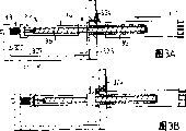
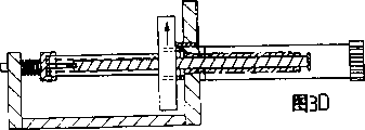
Fig. 3 A~3F represent a kind of based on independent device for clamping injection device and the construction machine formula of control device switch, wherein Fig. 3 A~3D represents each operational phase, and Fig. 3 F represents the details of injection device.
Fig. 4 A~4E schematically represents a kind of based on the injection device at different operating step piston bar and device for clamping unit construction.
Fig. 5 A~5E is the improvement of the embodiment of presentation graphs 4 schematically, is used to provide the automation of control device to switch.
Fig. 6 A~6D represents another kind of injection device based on piston rod and device for clamping and the combination of mechanical switching device shifter.
The specific embodiment
Figure 1A~1C schematically is illustrated in the injection device basic feature in three kinds of different operating stages.Be labeled as a front end 3, the rear end 5 of an opening and a piston 6 that can move that a cartridge case of 1 has an elongated shape cylindrical shell 2, has an outlet 4 along the inside of cylindrical shell 2.When cartridge case is two-chamber or multi-cavity type, a plurality of pistons can be set.Be labeled as that a pump of 10 or the parts that make up a prescription comprise a housing 11, a piston rod 12, device for clamping 13, locking system 14 and by the actuating device unit 15 shown in the dotted line.Piston rod 12 is manipulable and can moves with respect to housing, with close and mobile piston 6.Device for clamping 13 at least towards the direction of housing under the guiding of cartridge case rear end 5, be used for cartridge case 1 engagement and move it.The motion of locking system 14 restriction cartridge cases also can further be fixed its position.Actuating device unit 15 is used for power piston bar 12 and device for clamping 13, finishing its motion separately, and the switching of limiting control device, to guarantee correct order between the two.
In the stage of Figure 1A, a new cartridge case 1 is connected on the device 10, wherein device for clamping and cartridge case engagement, and the rearmost end of piston rod near or lean the piston 6 that is in ready position in this new cartridge case.Figure 1B represents cartridge case 1 have been moved in the housing 11 up to its relative position when this direction further mobile is subjected to the restriction of locking system 14 when device for clamping 13.Piston rod 12 remains on its rearmost end but still piston 6 is moved to the front end of cartridge case 1, and this moving is the result that cartridge case 1 is shifted to piston rod 12.In this stage, medicine can be discharged through opening 4 but preferably be carried out preparation (initiation) operation.In the stage of Fig. 1 C, with respect to cartridge case 1 and housing 11 both reaches, cartridge case 1 remains secured to locking system 14 with respect to housing 11 to piston rod 12 simultaneously.Piston rod 12 has moved on to piston 6 front position in the cylindrical shell 2 as a result, and piston rod can be in the extreme position of its far-end.In this stage, the content of cartridge case 1 can be by opening 4 injections.Various effects are adjusted by actuating device unit 15.Can expect and can adopt opposite order to use a new cartridge case, for example piston rod 12 is retracted to Figure 1B the position, discharge locking system 14 and make the front end 3 of cartridge case move apart housing 11 by activating device for clamping 13.
Fig. 2 representation class is similar to the injection device 20 of Fig. 1, and common feature adopts identical reference marker, but describes more in detail to device for clamping independently.This device for clamping comprises a sleeve pipe 21, and it has female thread 22, and this sleeve pipe axially is fixed in the housing 11, but can be rotated by the effect of actuating device unit 15.Cartridge case 1 has corresponding external screw thread 23, and also has the mesh splines on vertical spline and the housing front surface 25 to match in screw thread.Locking system 26 herein is provided with as the lateral inner surface on the rotating sleeve pipe 21.Piston rod 12 is similar to piston rod effect shown in Figure 1.Promptly cartridge case was drawn in the housing 11 but will be moved further to arrive locking system 26 between respectively by the stage shown in Figure 1A and the 1B operational phase of Fig. 2.The device for clamping of Fig. 2 can be operated by rotating casing 21, the rotation of its middle sleeve 21 makes cartridge case 1 being meshing with each other and moving axially between the external screw thread 23 of the female thread 22 of sleeve pipe 21 and cartridge case 1, does angular movement and spline 23,24 prevents cartridge case 1 respectively with respect to housing 11.This motion is sustainable to be abutted on the locking system surface 26 up to cartridge case 1, and locking intensity herein can the bolt effect through being obtained reach arbitrary value.Sleeve pipe 21 rotation in the opposite direction will discharge cartridge case 1 and make it move apart housing 11.As shown in Figure 1, in the device for clamping operating process, piston rod 12 can remain fixed in its near-end.
Fig. 3 A~3F represents a kind of injection device that the machinery based on independently device for clamping and control device switches, and wherein Fig. 3 A~3D represents the various operational phases, and the details of Fig. 3 F indication device.A kind of dosage adjustment (a making up a prescription) device feature 30 and a cartridge components 31 have been shown in Fig. 3 A~3E.The deployment device parts comprise a housing 32 of underframe type, and it has a base plate 321 and two vertical walls 322,323, and wherein vertical wall has the dead eye that is used for movable part.The lock pin 324 that one spring is exerted pressure is arranged on the wall 323 near the dead eye place.Movably parts comprise spring-loaded axle head parts 33, a driver 34, a threaded collar tube sub-assembly 35 and a piston rod 36, and these parts are further detailed to be shown among Fig. 3 F.Axle head parts 33 comprise a pivot 331, a spring 332 and are used for a pit 333 of driver 34 ends.Driver 34 comprises a pipe 341, it is suitable for holding piston rod 36 and has a guide groove 342, a pinion 343 and be used to be connected to connecting pin 344 on the threaded sleeve pipe 35, threaded sleeve pipe 35 has a flange 351, its structure can be held connecting pin 344, female thread 352, one pipe parts 353 and the external screw thread on the pipe parts 354 near flange.Cartridge case 31 has a rear end 311, is positioned at the female thread 312 of rear end, be used for sleeve pipe 35 on external screw thread match a container parts 313, spline 314 and a front end 315 that extends to the right.Shown cartridge case 31 can be the shell of a syringe cylinder or itself just be used as syringe cylinder.Piston rod 36 comprises a follower pin 361, is used for matching with guide groove 342, has an externally threaded axostylus axostyle 362 and is used for a push plate 363 with a plunger engages.Get back to Fig. 3 A, can see the assembling situation of parts.Axle head parts 33 are contained in the end of driver 34 in the pit 333, and the connecting pin 344 of driver 34 other ends can or not with the flange 351 of threaded sleeve pipe 35 in the corresponding construction engagement, this point below will be described in further detail.Thereby threaded sleeve pipe 35 inserts inboard and its pipe parts 353 of its flange 351 abutment walls 323 of a hole of wall 323 to be extended from housing 32.The external screw thread 354 of sleeve pipe 35 is suitable for matching with the female thread 312 of cartridge case 31.The spline 314 of cartridge case matches with the engaging structure (not shown) on the housing 32, rotates to prevent cartridge case 31.Piston rod 36 inserts the pipe parts 353 of driver pipe 341 and threaded sleeve pipe 35; thereby follower pin 361 moves in the guide groove 342 of driver 34; to guarantee that piston rod 36 rotates with driver 34; and thereby the female thread on the external screw thread of bar 362 and the sleeve pipe 35 matches, and moves axially when rotating with respect to sleeve pipe 35 with appropriate guarantor's bar 36.
The operation of this injection device is shown in Fig. 3 A~3E.Piston rod 36 in Fig. 3 A is in external screw thread 354 engagements of female thread 312 with the sleeve pipe 35 of punctured position and cartridge case 31.Driver connecting pin 344 meshes with sleeve pipe 35 under the pressure of spring 332, and when the direction of arrow of driver 34 on gear 343 is rotated, sleeve pipe 35 all rotates with piston rod 36, and because cartridge case 31 is meshing with each other with sleeve pipe 35 screw threads and the nonrotational property that produces owing to spline, so the direction of arrow of cartridge case on 31 along its is pulled to housing 32.Cartridge case 31 among Fig. 3 B has arrived and has abutted on the wall 323.When arriving, the lock pin 324 that its hole pushing spring in wall is exerted pressure so that driver 34 overcomes spring 332 and move, and makes connecting pin 344 separate with sleeve pipe 35.This moment, driver 34 can freely be rotated with respect to sleeve pipe 35 and female thread 352 thereof with piston rod 36.In Fig. 3 C pinion 343 be rotated further that to make the engagement of piston rod 36 by itself and fixed screw thread 352 move forward the order that produces among the pushing action diagram 3D be converse, wherein along the rightabout transmitting gear shown in the arrow.Rotation causes that piston rod 36 almost turns back to its punctured position, because 352 engagements of itself and screw thread.In Fig. 3 E,, prevent that piston rod 36 from further moving backward, and the engagement at screw thread 352 places makes again sleeve pipe 35 beginnings with piston rod 36 rotations by contacting between the far-end of push plate 363 and sleeve pipe 35.Separate release lock pin 324 first time of cartridge case 31, wherein lock pin is pressed to its position by spring, and allows connecting pin 344 will be affixed on the sleeve pipe 35.Gear 343 further rotates and makes cartridge case 31 move apart housing 32 along the direction of arrow.
Very clear, in the enforcement of just having described was fallen, threaded sleeve pipe 35 was as device for clamping, wall 323 is as locking system, it also can be used as locking system by the screw thread on bolt, and driver 34 is as parts of actuating device, so that device for clamping and piston rod motion.Actuating device also comprises the switching of control device, wherein control device is described various control characteristic formp, the control that it is guaranteed desired stage order and reduces gear is rotated at one or other direction, this control can manually be carried out but preferably be carried out through geared system by a motor.Triggering among Fig. 3 B is carried out when cartridge case 31 arrives walls 323, and its contact comprises the axially-movable of lock pin 324 and driver, and this motion fails device for clamping and piston rod is moved forward.Triggering among Fig. 3 E is carried out when push plate 363 arrives sleeve pipe 35, and this makes device for clamping work (enable) and removes the effect (disable) of piston rod.
Fig. 4 A~4E schematically represented a kind of based on combination piston rod and the injection device of device for clamping parts in the situation in different operating stage.Not shown housing and only show main movable part.From right to left, this device comprises a cartridge case 41 that has an intermediate flange 42, wherein has the spline (not shown) on the intermediate flange 42.Not only had a driving wheel 44 as piston rod but also as one 43 of device for clamping, this take turns with axle on for example flat surface engaged, move axially to allow axle; Also has a flange 45 that is positioned at its rear end.This has external screw thread except that being used to take turns 44 flat surface, and in the embodiments of figure 3, the female thread engagement that in described external screw thread and the cartridge case 41 matches, wherein said cartridge case is because cooperating and can not rotate between the corresponding construction on the spline on the flange 42 and the housing.A mechanical brake 46 can be upper and lower the moving in flange 45 backs, to discharge or to prevent that axle 43 from moving forward.One similar cartridge case mechanical brake 47 can be upper and lower the moving in intermediate flange 42 back of cartridge case, to discharge or to prevent its reach.
Among Fig. 4 A mechanical brake 46 activated and axle 43 rotation make cartridge case 41 since the female thread of the external screw thread of axle 43 and cartridge case 41 be meshing with each other and move along the direction of arrow.Cartridge case 41 has arrived a back-end location and has activated mechanical brake 47 to prevent its reach at this moment among Fig. 4 B, removes mechanical brake 46 simultaneously to allow axle 43 reaches.Among Fig. 4 C, axle 43 is in the unidirectional foremost position of axle being shifted in the cartridge case 41 that is rotated further, but this moment, rotation direction was reversed, and moved after making axle 43 as shown by arrows.Fig. 4 D axis 43 arrives its rear end again and activates mechanical brake 46 axle is remained on this position, removes mechanical brake 47 simultaneously allowing cartridge case 41 reaches, and with Fig. 4 C in unidirectional being rotated further make cartridge case move along the direction of arrow.Cartridge case 41 has arrived identical among its foremost position and this position and Fig. 4 A among Fig. 4 E.Available one new cartridge case is changed this cartridge case and is repeated this circulation.
This embodiment shows and can adopt same device as piston rod and device for clamping.The switching of control is to be undertaken by mechanical brake 46,47, for example can be by carry out the electro-mechanical operation separately or in phase such as electromagnetic valve.Control system only need be controlled the forward and backward rotation of these two mechanical brakes and motor, can detect the axle and the end position of cartridge case with pick off.
Fig. 5 A~5E represents the embodiment same substantially with Fig. 4, just schematically shows some and revises, and switches so that the mechanical type to handling control to be provided.The reference marker that has kept Fig. 4.The lower surface of axle mechanical brake 46 and cartridge case mechanical brake 47 is cut into taper and places by under the downward spring pressure shown in the arrow 50,51.This layout allow when cartridge case flange when figure moves left 42 by under the mechanical brake 47 and allow axial flange 45 to pass through under the mechanical brake 46, but prevent that them from moving right.Preferably referring to Fig. 5 B, a cartridge sensor 52 that is pushed away to the right by spring as shown in arrow 54 is to be provided with in this wise, to such an extent as to arrive its rearmost end this pick off is moved to left by cartridge case, and this motion can pass to a mechanical brake 46, and this moment, mechanical brake was owing to conical surface 53 and the cooperating of a corresponding conical surface on the mechanical brake 46 lift.Be used to lift the required cartridge case axially-movable of effect and be shown in 55.Preferably referring to Fig. 5 D, axle sensor 56 by the spring pressed rightwards as shown in arrow 58 is provided with like this, to such an extent as to can arrive its rear end this pick off is moved to left by the flange 45 of axle, and this motion can pass to cartridge case mechanical brake 47, this by conical surface 57 with cooperating of a respective surfaces make it to lift on the mechanical brake 47.The axially-movable that is used to the required axle of the effect of lifting is shown in 59.Described feature is used for cancelling mechanical brake 46 and the 47 this demands controlled respectively, and reduces axle and rotate required effect in either direction.
Manipulation difference with respect to Fig. 4 is described below.Stage shown in Fig. 5 A is handled in the mode identical with Fig. 4 A, i.e. one of axle 43 rotation causes that cartridge case 41 moves to left.In this embodiment, cartridge case mechanical brake 47 can slide along cartridge case, up to being lifted by flange 42.In Fig. 5 B, cartridge case 41 arrives its rearmost position and cartridge sensor 52 is moved to left, and lifts a mechanical brake 46 thus, and axle 43 can freely be moved forward.In its motion, cartridge case flange 42 is also by cartridge case mechanical brake 47, and this mechanical brake at first is lifted and drops to the flange back then, does not allow its reach with the locking cartridge case.Fig. 5 C such as Fig. 4 C ground are handled, and promptly axle 43 makes the axle reach unidirectional foregoing being rotated further, to discharge the content in the cartridge case.As long as cartridge case 41 remains on its rearmost position, axle mechanical brake 46 just remains on the high position with the same reason of Fig. 5 B.In Fig. 5 D, as Fig. 4 D, backward rotation brings back to its rearmost position with axle 43.At this, it is with axle sensor 56 pushers, and wherein this pusher motion is converted to the effect of lifting that acts on the cartridge case mechanical brake 47, makes cartridge case 41 freely to move forward.Fig. 5 E axis 43 moves on to cartridge case the position same as Fig. 5 A unidirectional being rotated further.In case cartridge case leaves its rearmost position, cartridge sensor 52 is reach just, makes a mechanical brake 46 be free state, and mechanical brake fell and stoped axle 43 not allow its reach this moment.After flange 42 passed through, cartridge case mechanical brake 47 both can be high, also can be low.
Fig. 6 A~6D represents based on the piston rod and the device for clamping of a combination and has the another kind of injection device of mechanical type switching device shifter.Fig. 6 A and 6B represent not to be with two views of the device inside of housing.Fig. 6 C represents the parts of near-end, has wherein used the cervical region of cartridge case.Fig. 6 D represents the locking of injection device and a view that amplifies of switching device shifter.Cartridge case 61 be shown among Fig. 6 A and the 6B, be connected to a guide groove 62 on the housing, substantially by one of 63 expressions activate devices, as one threaded 64, the follower unit 65 and a lockable mechanism 66 of piston rod and device for clamping.Can see a shell on cartridge case 61, at the glass cylindrical shell that this enclosure has a simple designs, this glass cylindrical shell has at least one piston.Preferably referring to Fig. 6 C, there is a flange 612 at the rear portion of shell 611, and its diameter is slightly less than the diameter of master unit 611; Also have a cervical region 613, be used for meshing with locking system.Rear aperture 614 has the female thread (not shown), is used for matching with threaded axle 64.Guide groove 62 has the interior profile of semi-circular cross section, and outline of profile and cartridge case 61 adapts in this.Actuating device 63 comprises a motor 631, it has gear 632, its middle gear 632 matches with a gear wheel 633 that is connected on the gear shaft 634, the rear portion that is supported on bearing 635 and stretching to an elongated hollow cavity in the axle 64 forwards to, gear shaft 634 is meshed with the cavity of axle 64, but not circular cross section, to allow axle 64 axially-movable with coming from actuating that gear shaft 634 kept.Axle is shaped on screw thread on 64, matches and its rear portion is pivotally connected on the follower unit 65 with the female thread with cartridge case 61.This follower unit 65 comprise be positioned at wall 652 be used for an axle bearing 651 of 64 and two arms 653 that stretch out forward from wall 652.Preferably referring to Fig. 6 D, arm 653 ends at the conical surface 654 and following stop surfaces 655.Locking system 66 comprises a locking piece 661, and it is guided in the housing and by spring 662 and presses to a upper/lower positions.Locking piece 661 has a upper fork part spare 663, and this upper fork part spare has the following conical surface 664, be used for arm 653 on stop surface 655 match; Also have fork part 665, the stop surface 655 when it lifts and on the arm 653 matches, the stop arm reach.Lower fork 665 has a width that is suitable for entering cervical region 613, and wherein this cervical region is between the cylindrical shell 611 and flange 612 of cartridge case.Gap between last fork 663 and the lower fork 665 is suitable for allowing arm 653 to pass through.Make a support ring 666 slightly move axially and be pressed towards forward a position by spring 667, and move it stable by matching of the groove 669 in the projection on the ring 668 and the guide groove 62.Support ring 666 and cartridge case 61 coaxial and have with cartridge case 61 on the roughly the same diameter of flange 612, and when ring 666 during in its forward position, be used for locking piece 661 is remained on its higher position, and, allow locking piece 661 to be pressed towards position lower in the cervical region 613 when ring 666 during by cartridge case flange 612 pushers.
Total mode of operation of the injection device of Fig. 6 is similar in conjunction with Fig. 4 described, promptly axle 64 rotates along its punctured position, cartridge case 61 is pulled back into a lock position, then by make axle 64 reaches in the successive rotation of same direction, to discharge the content of cartridge case 61, the axle 64 that oppositely makes that rotates turns back to its punctured position, discharges cartridge case 61 and makes it to remove in unidirectional continuous rotation by axle 64.Locking and switching device shifter are described its operation according to Fig. 6 D below with shown in Figure 4 different.In the moment shown in Fig. 6 D, axle 65 (not shown) are almost in its rearmost position.Locking piece 661 abuts on the support ring 666, allows cartridge case flange 612 below locking piece, and stop surface 655 engagements of lower fork 665 and arm 653, to stop follower unit 65 and axle 64, does not allow their move forward.The flange 612 that axle 64 rotations that move direction after making flange 612 will allow cartridge case 61 to push support ring 666 open and to allow locking piece 661 to drop in the cartridge case cervical region 613, meanwhile makes axle 64 freely move forward below the locking piece 661 that lifts.Make the converse conical surface engagement that will make tapered end 654 with the last fork 663 of arm 653 of axle 64 rotation direction, impel locking piece in cervical region 613, to lift, allow flange 612 and support ring 666 below locking piece 661, and stop arm 653 does not allow its reach once more.Cartridge case can move fully and the axle can not move between this two states fully, allow certain axial action.
When axle 64 during in its rearmost position, can begin an operation cycle, wherein locking piece is raised to its higher position, and is fixed to this position by support ring 666, and support ring pushes away before by spring 667, stops travelling forward but allowing cartridge case flange 612 to pass through of axle thus.Even at its punctured position, axle also extends far away outside the lockable mechanism 66, and can connect cartridge case in its end by the rotation of axle, meshes with the female thread with cartridge case.The rotation of axle will impel cartridge case to shift to lockable mechanism, and related flange 612 is together by below the locking piece 661, meanwhile mobile backward support ring 666, and stop it further to move axially by contacting between locking piece and the big cartridge case master unit 611.This moment, locking piece 661 can drop in the cartridge case cervical region 613, with locking cartridge case and arm 653 can fully freely be moved forward.In the successive rotation of same direction axle 64 and follower unit 65 will be moved forward, to discharge the content of cartridge case.After the discharge, move after making axle 64 backward rotation and follower unit 65 and axle 64, cartridge case 61 is still by locking piece 661 lockings that are in its lower position simultaneously.When axle 64 with follower 65 during near its rearmost position, tapered end 654 beginnings of arm 653 and the conical surface 664 engagements of last fork 663, and overcome the pressure of spring 662 and lift locking piece 661 from cartridge case cervical region 613, to allow support ring 666 and cartridge case flange 612 below locking piece, thereby lower fork 665 basically with the engagement of the stop surface of wall 653, to stop follower unit 65 and axle 64, do not allow its reach.Make cartridge case 61 reaches of locking this moment in the successive rotation of same direction, support ring 666 moves in locking piece 661 times, to fix its position, up to unloading cartridge case.Very clear, as long as cartridge case is not in its lock position, axle 64 just can not move axially, this moment, locking piece 661 was at its lower position, and before its last position, cartridge case still can not move axially up to axle 64 and follower 65, and be raised to its higher position with locking piece 661 this moment, and except axle the rotation of either direction, need not other control action.
Cited embodiment is exemplary, can not be understood as that to limit the scope of the invention and universality.
Claims (44)
1. injection device, comprising: an a) housing (11), a b) cartridge case (1), this cartridge case contain medicament or are used for the precursor component of medicament and have a front portion (3) and a rear portion (5), the axis of wherein said front portion and rear portion definition cartridge case; Also have an outlet (4) that is used for medicament, it is arranged on the front portion; And be arranged at least one movably wall (6) between front portion and the rear portion, the mobile medicament that makes of this wall is shifted to or is discharged through outlet, c) piston rod (12), it has one first end and one second end, and be at least partially housed in the housing (11), and can be operated with by its first end engagement and mobile described movably wall (6), d) be arranged on the actuating device (15) that moves described at least bar in the housing, it is characterized in that its improvements comprise:
Device for clamping (13), it is connected on the housing and is used to hold cartridge case (1) or its shell, and its front portion is away from the then close housing in housing rear portion;
Described actuating device (15) is used for moving described device for clamping (13), and is mobile with respect to housing (11) to make cartridge case (1) under the guiding at device for clamping rear portion; With
Described actuating device (15) can make piston rod (12) move between at least one punctured position and at least one extension position.
2. device as claimed in claim 1 is characterized in that:
Cartridge case (1) comprises that one has the container (2) of constant interior cross section, and described movably wall (6) is a piston-type.
3. device as claimed in claim 1 is characterized in that:
Cartridge case (1) is two-chamber or multi-cavity type, has one or more independently midfeathers and contain to carry out blended precursor component before use.
4. device as claimed in claim 1 is characterized in that:
Cartridge case (1) comprises a container (2), its internal diameter between 2~20mm, length-diameter ratio between 2~20, this depend on preparation back but make up a prescription and inject before the volume of medicament.
5. device as claimed in claim 1 is characterized in that:
Housing (11) forms a container, and it coats at least a portion, device for clamping (13), locking system (14) and at least some actuating devices (15) of piston rod (12).
6. device as claimed in claim 1 is characterized in that:
When holding cartridge case but at mobile device for clamping (13) before, housing (11) is near cartridge case (1) end.
7. device as claimed in claim 1 is characterized in that:
When being in the lock position, housing (11) is upheld along cartridge case (1) at least in part.
8. device as claimed in claim 5 is characterized in that:
Housing (11) has whole or in part the opening around cartridge case (1), and its size and shape is suitable for allowing to hold cartridge case and carries out it and move to small part.
9. device as claimed in claim 1 is characterized in that:
Housing (11) along the length of cartridge case (1) axis with respect to the ratio of the total length of cartridge case giving drugs into nose dosage before discharging more than or equal to 1, and less than 10.
10. device as claimed in claim 1 is characterized in that:
When piston rod (12) when being in punctured position, its second end is limited in the housing (11).
11. device as claimed in claim 1 is characterized in that:
Piston rod has screw thread at least on its partial-length, and the actuating device that is used for mobile piston comprises the screw-and-nut configuration (614) that matches, and has one and be driven part.
12. device as claimed in claim 11 is characterized in that:
In described screw-and-nut configuration, actuating device rotary nut parts also provide the device that prevents that piston rod part from rotating simultaneously.
13. device as claimed in claim 11 is characterized in that:
In described screw-and-nut configuration, actuating device turns piston rod part, and the device that prevents that nut part from rotating also is provided simultaneously.
14. device as claimed in claim 1 is characterized in that:
Actuating device comprises motor apparatus (631).
15. device as claimed in claim 14 is characterized in that:
Motor apparatus comprises at least one motor.
16. device as claimed in claim 1 is characterized in that:
Actuating device comprises an energy of the energy that contains storage.
17. device as claimed in claim 16 is characterized in that:
The energy comprises at least one power supply.
18. device as claimed in claim 1 is characterized in that:
The length of piston rod (12) is less than cartridge case (1) in the rear portion of wall (6) movably and cartridge case between anterior (3) 2 times of length but be at least 1.1 times.
19. device as claimed in claim 1 is characterized in that:
Device for clamping (13) is independently with piston rod (12).
20. device as claimed in claim 19 is characterized in that:
Actuating device (15) comprises motor apparatus, is used for driving the motion of device for clamping (13) motion or piston rod (12), and is provided with switching device shifter and switches engagement between them.
21. device as claimed in claim 1 is characterized in that:
Piston rod is configured to device for clamping.
22. device as claimed in claim 21 is characterized in that:
Piston rod part and cartridge components have respective threads (614), and these parts can back and forth rotate with mobile cartridge case.
23. device as claimed in claim 22 is characterized in that:
Piston rod part is configured to turn, and cartridge components cannot not be configured to rotatablely.
24. device as claimed in claim 22 is characterized in that:
In the cartridge case moving process, the threaded portion of piston rod inserts cartridge interior.
25. device as claimed in claim 22 is characterized in that:
Screw thread on the piston rod both had been used for cartridge case is moved with respect to housing, was used for making piston rod to move with respect to housing again, so that the distribution of medicament is disposed.
26. device as claimed in claim 25 is characterized in that:
Actuating device comprises motor apparatus (631), is used for driving cartridge case motion or piston rod movement, and is provided with switching device shifter (65,66), to switch these motions.
27. device as claimed in claim 1 is characterized in that:
Device for clamping (13) comprises connecting device and mobile device, and this connecting device is used for cartridge case (1) is appended on the mobile device.
28. device as claimed in claim 27 is characterized in that:
Connecting device comprises a frame that is used for cartridge case, and this frame is connected on the device for clamping and has the locking feature, is used for releasably connecting cartridge case (1).
29. device as claimed in claim 1 is characterized in that:
Comprise a locking system (14), but its locking cartridge case (1) does not allow it move axially with respect to housing (11), defines a lock position of cartridge case thus.
30. device as claimed in claim 29 is characterized in that:
Operable locks locking apparatus (14) comes the locking cartridge case, does not allow it move axially and rotates.
31. device as claimed in claim 29 is characterized in that:
When engagement, the operable locks locking apparatus prevents to unload cartridge case, and is provided with control device (654,664) and stops disengagement, unless piston rod is in its punctured position.
32. device as claimed in claim 1 is characterized in that:
It comprises an exercisable switching device shifter (65,66), to make the state that device for clamping can move with respect to housing at least and piston rod can not be switched between the axially movable state with respect to housing in an operation cycle, wherein the latter is a kind of switching of opposite or contrary.
33. device as claimed in claim 32 is characterized in that:
Switching device shifter (65,66) can be in response at least one trigger mechanism that switches.
34. device as claimed in claim 33 is characterized in that:
Switching device shifter (66) constitutes a trigger mechanism, and it makes device for clamping inoperative and piston rod is worked, and arrive the lock position with device for clamping or cartridge case or its actual locking relevant.
35. device as claimed in claim 33 is characterized in that:
Switching device shifter (66) constitutes a trigger mechanism, and it works device for clamping and makes piston rod inoperative, and to arrive its punctured position relevant with piston rod.
36. device as claimed in claim 33 is characterized in that:
Switching device shifter (65,66) comprises transfer device (661), is used for release with trigger mechanism and passes to respectively and parts are worked and do not make its device that works (654,664,653,655), and wherein transfer device is mechanical.
37. device as claimed in claim 32 is characterized in that:
When cartridge case during, can operate switching device shifter (65,66) piston rod is moved axially, and, can make the device for clamping motion of cartridge case when piston rod during at its punctured position in its lock position.
38. device as claimed in claim 32 is characterized in that:
Make parts work and its switching of working is carried out simultaneously.
39. device as claimed in claim 32 is characterized in that:
Actuating device comprises motor apparatus (631), is used for the motion of device for clamping and piston rod, and switching device shifter (65,66) is carried out the switching to engagement.
40. device as claimed in claim 1 is characterized in that:
The relative position that is in the piston rod (12) of punctured position and is between the cartridge case (1) of lock position is set like this, crosses the movably initial position of wall (6) in cartridge case in the cartridge case to such an extent as to piston rod stretches into.
41. device as claimed in claim 1 is characterized in that:
Comprise a locking system, be used for setting several lock positions along the cartridge case movement locus.
42. device as claimed in claim 41 is characterized in that:
Be independent of piston rod device for clamping is set,, thereby provide described several lock position so that cartridge case is in several position motion with stop.
43. device as claimed in claim 1 is characterized in that:
It comprises the position detecting device that has control device, is used for preventing or allow to operate this injection device at described injection device preposition.
44. device as claimed in claim 1 is characterized in that:
It comprises a pick off, is used to detect at least one cartridge case parameter.
Applications Claiming Priority (5)
| Application Number | Priority Date | Filing Date | Title |
|---|---|---|---|
| SE9602611A SE9602611D0 (en) | 1996-07-01 | 1996-07-01 | Injection device and method for its operation |
| SE96026117 | 1996-07-01 | ||
| US2129396P | 1996-07-09 | 1996-07-09 | |
| US06/021,293 | 1996-07-09 | ||
| PCT/SE1997/001093 WO1998000188A1 (en) | 1996-07-01 | 1997-06-18 | Injection device and method for its operation |
Related Child Applications (1)
| Application Number | Title | Priority Date | Filing Date |
|---|---|---|---|
| CNA2004100797994A Division CN1589916A (en) | 1996-07-01 | 1997-06-18 | Injection device and method for its operation |
Publications (2)
| Publication Number | Publication Date |
|---|---|
| CN1224364A CN1224364A (en) | 1999-07-28 |
| CN1176727C true CN1176727C (en) | 2004-11-24 |
Family
ID=26662698
Family Applications (2)
| Application Number | Title | Priority Date | Filing Date |
|---|---|---|---|
| CNA2004100797994A Pending CN1589916A (en) | 1996-07-01 | 1997-06-18 | Injection device and method for its operation |
| CNB971960666A Expired - Fee Related CN1176727C (en) | 1996-07-01 | 1997-06-18 | Injection device and method for its operation |
Family Applications Before (1)
| Application Number | Title | Priority Date | Filing Date |
|---|---|---|---|
| CNA2004100797994A Pending CN1589916A (en) | 1996-07-01 | 1997-06-18 | Injection device and method for its operation |
Country Status (20)
| Country | Link |
|---|---|
| US (1) | US6042571A (en) |
| EP (1) | EP0921828B1 (en) |
| JP (1) | JP2000513261A (en) |
| KR (1) | KR100383477B1 (en) |
| CN (2) | CN1589916A (en) |
| AT (1) | ATE233111T1 (en) |
| AU (1) | AU713846B2 (en) |
| BR (1) | BR9710121A (en) |
| CA (1) | CA2259442C (en) |
| CZ (1) | CZ294265B6 (en) |
| DE (1) | DE69719335T2 (en) |
| DK (1) | DK0921828T3 (en) |
| ES (1) | ES2193383T3 (en) |
| HU (1) | HUP0000104A3 (en) |
| IL (1) | IL127618A (en) |
| NO (1) | NO316312B1 (en) |
| PL (1) | PL185530B1 (en) |
| PT (1) | PT921828E (en) |
| TW (1) | TW486375B (en) |
| WO (1) | WO1998000188A1 (en) |
Cited By (1)
| Publication number | Priority date | Publication date | Assignee | Title |
|---|---|---|---|---|
| CN101287511B (en) * | 2005-04-06 | 2011-06-22 | 西拉格国际有限公司 | Injection device |
Families Citing this family (68)
| Publication number | Priority date | Publication date | Assignee | Title |
|---|---|---|---|---|
| DE19822031C2 (en) | 1998-05-15 | 2000-03-23 | Disetronic Licensing Ag | Auto injection device |
| DE19900827C1 (en) | 1999-01-12 | 2000-08-17 | Disetronic Licensing Ag | Device for the dosed administration of an injectable product |
| DE19900792C1 (en) | 1999-01-12 | 2000-06-15 | Disetronic Licensing Ag | Injection unit forming part of e.g. pen-type self-injection syringe has continuous dosing stop in spiral form with constant pitch ensuring close fine control and accuracy in use |
| IL156245A0 (en) * | 2000-12-22 | 2004-01-04 | Dca Design Int Ltd | Drive mechanism for an injection device |
| US6673049B2 (en) | 2001-02-15 | 2004-01-06 | Disetronic Licensing Ag | Injection device for injecting fluid |
| GB0107608D0 (en) * | 2001-03-27 | 2001-05-16 | Dca Design Int Ltd | Improvements in and relating to an injection device |
| EP1384003B1 (en) * | 2001-04-27 | 2007-07-18 | HydroCision, Inc. | High pressure pumping cartridges for medical and surgical pumping and infusion applications |
| ITMI20011666A1 (en) * | 2001-07-31 | 2003-01-31 | Inge Spa | MULTIFUNCTIONAL DEVICE FOR THE DISPENSING OF MEDICINAL SUBSTANCES |
| DE10147973A1 (en) * | 2001-09-28 | 2003-04-17 | Disetronic Licensing Ag | ampoules recognition |
| DE10151471A1 (en) * | 2001-10-18 | 2003-05-15 | Disetronic Licensing Ag | Injection device with energy storage |
| MY139059A (en) | 2002-06-24 | 2009-08-28 | Alza Corp | Reusable, spring driven autoinjector |
| DE602004005962T2 (en) * | 2003-01-17 | 2007-08-30 | Dentsply International Inc. | STICKY LIQUID DISPENSER |
| JP4904283B2 (en) | 2004-12-01 | 2012-03-28 | アキュショット インク | Needleless syringe |
| JP2008529689A (en) * | 2005-02-21 | 2008-08-07 | ノボ・ノルデイスク・エー/エス | Method of keeping the motor speed in the injection device constant |
| US9011386B2 (en) * | 2005-06-01 | 2015-04-21 | Shl Group Ab | Device for delivering medicament |
| ITVI20050187A1 (en) | 2005-06-28 | 2006-12-29 | Tecres Spa | CARTRIDGE FOR STERILE MIXING OF A BIPHASIC COMPOUND, PERTICULARLY FOR BICOMPONENT ACRYLIC RESINS |
| US20070055199A1 (en) | 2005-08-10 | 2007-03-08 | Gilbert Scott J | Drug delivery device for buccal and aural applications and other areas of the body difficult to access |
| JP5241714B2 (en) | 2006-07-07 | 2013-07-17 | プロテウス デジタル ヘルス, インコーポレイテッド | Smart parenteral delivery system |
| JPWO2008007674A1 (en) * | 2006-07-11 | 2009-12-10 | 株式会社根本杏林堂 | Chemical filling device |
| DE102006048180A1 (en) * | 2006-10-10 | 2008-04-17 | Tecpharma Licensing Ag | Injection device with a trigger lock with not inserted product container |
| DE102007002096A1 (en) * | 2007-01-09 | 2008-07-10 | B. Braun Melsungen Ag | Device for injecting liquids |
| US9125979B2 (en) | 2007-10-25 | 2015-09-08 | Proteus Digital Health, Inc. | Fluid transfer port information system |
| DE102007054868A1 (en) * | 2007-11-07 | 2009-05-20 | Arzneimittel Gmbh Apotheker Vetter & Co. Ravensburg | Device and method for mounting a pharmaceutical application aid |
| JP5662337B2 (en) * | 2008-12-09 | 2015-01-28 | ベクトン・ディキンソン・アンド・カンパニーBecton, Dickinson And Company | Open and close valve drug delivery system for high pressure injection |
| CN102307605B (en) | 2009-02-05 | 2014-09-03 | 赛诺菲-安万特德国有限公司 | Medicament delivery devices |
| US8221433B2 (en) | 2009-05-26 | 2012-07-17 | Zimmer, Inc. | Bone fixation tool |
| EP2482879B1 (en) * | 2009-09-30 | 2016-11-09 | Sanofi-Aventis Deutschland GmbH | Method and assembly for a drug delivery device |
| US9795744B2 (en) | 2009-12-15 | 2017-10-24 | Shl Group Ab | Medicament delivery device |
| US10322244B2 (en) | 2009-12-15 | 2019-06-18 | Shl Group Ab | Medicament delivery device |
| US10322243B2 (en) | 2009-12-15 | 2019-06-18 | Shl Group Ab | Medicament delivery device |
| EP2512561B1 (en) | 2009-12-15 | 2016-04-13 | SHL Group AB | Medicament delivery device |
| USD823459S1 (en) | 2009-12-15 | 2018-07-17 | Shl Group Ab | Medical injector |
| CN102905612A (en) | 2010-02-01 | 2013-01-30 | 普罗秋斯数字健康公司 | Two-wrist data gathering system |
| JP5841951B2 (en) | 2010-02-01 | 2016-01-13 | プロテウス デジタル ヘルス, インコーポレイテッド | Data collection system |
| AU2013224349A1 (en) | 2012-02-24 | 2014-08-21 | Novo Nordisk A/S | Drug delivery device with front loading feature |
| EP3225205A2 (en) | 2012-07-11 | 2017-10-04 | Zimmer, Inc. | Bone fixation tool |
| ES2659491T3 (en) | 2012-09-05 | 2018-03-15 | E3D Agricultural Cooperative Association Ltd. | Electronic self-injection device |
| JP6047371B2 (en) * | 2012-10-31 | 2016-12-21 | 株式会社ハイレックスコーポレーション | Open / close drive device |
| US20140336577A1 (en) * | 2013-05-07 | 2014-11-13 | Jewis J. McCoy | Auto-injector syringe |
| EP3049132B1 (en) | 2013-09-26 | 2020-08-19 | Companion Medical, Inc. | System for administering a medicament |
| CN105848696A (en) * | 2014-02-28 | 2016-08-10 | 崔奎东 | Device and method for injecting drug |
| WO2015153981A2 (en) | 2014-04-03 | 2015-10-08 | Zimmer, Inc. | Orthopedic tool for bone fixation |
| EP3659651A3 (en) | 2014-07-10 | 2020-10-14 | Companion Medical, Inc. | Medicine administering system including injection pen and companion device |
| EP3233156A4 (en) * | 2014-12-19 | 2019-01-30 | Smiths Medical ASD, Inc. | Compact medical infusion pumps |
| WO2017060899A2 (en) | 2015-10-05 | 2017-04-13 | E3D Agricultural Cooperative Association Ltd. | Infusion pump device and method for use thereof |
| EP3407940A4 (en) | 2016-01-29 | 2019-09-04 | Companion Medical, Inc. | Automatic medication delivery tracking |
| CN106236317A (en) * | 2016-08-26 | 2016-12-21 | 中国科学院深圳先进技术研究院 | A kind of trace injection instrument |
| EP3581219A4 (en) * | 2017-02-08 | 2020-08-26 | Nemoto Kyorindo Co., Ltd. | Injection device, actuator, and injection device production method |
| WO2018227163A1 (en) | 2017-06-09 | 2018-12-13 | Companion Medical, Inc. | Intelligent medication delivery systems and methods |
| EP3694583A4 (en) | 2017-10-12 | 2021-08-04 | Companion Medical, Inc. | Intelligent medication delivery systems and methods for dose recommendation and management |
| US10987464B2 (en) | 2017-12-12 | 2021-04-27 | Bigfoot Biomedical, Inc. | Pen cap for insulin injection pens and associated methods and systems |
| US11116899B2 (en) | 2017-12-12 | 2021-09-14 | Bigfoot Biomedical, Inc. | User interface for diabetes management systems and devices |
| EP3724888A1 (en) | 2017-12-12 | 2020-10-21 | Bigfoot Biomedical, Inc. | Therapy management systems, methods, and devices |
| US11083852B2 (en) | 2017-12-12 | 2021-08-10 | Bigfoot Biomedical, Inc. | Insulin injection assistance systems, methods, and devices |
| US11077243B2 (en) | 2017-12-12 | 2021-08-03 | Bigfoot Biomedical, Inc. | Devices, systems, and methods for estimating active medication from injections |
| US11464459B2 (en) | 2017-12-12 | 2022-10-11 | Bigfoot Biomedical, Inc. | User interface for diabetes management systems including flash glucose monitor |
| BR112020011830A2 (en) | 2017-12-13 | 2020-11-24 | Regeneron Pharmaceuticals, Inc. | devices and methods for precision dose distribution |
| US11664107B2 (en) | 2018-05-08 | 2023-05-30 | Medtronic Minimed, Inc. | Intelligent medication delivery systems and methods using a prescription-regulated software application |
| US10898653B2 (en) | 2018-05-08 | 2021-01-26 | Companion Medical, Inc. | Intelligent medication delivery systems and methods for dose setting and dispensing monitoring |
| USD893020S1 (en) | 2018-05-11 | 2020-08-11 | Companion Medical, Inc. | Injection pen |
| USD892819S1 (en) | 2018-06-20 | 2020-08-11 | Companion Medical, Inc. | Display screen with graphical user interface |
| US11587663B2 (en) | 2018-06-20 | 2023-02-21 | Medtronic Minimed, Inc. | Intelligent medication delivery systems and methods for medicine dose calculation and reporting |
| CN109350297A (en) * | 2018-11-07 | 2019-02-19 | 浙江康瑞器械科技股份有限公司 | Intelligent animal doctor's automatic injector |
| US11948671B2 (en) | 2019-04-11 | 2024-04-02 | Medtronic Minimed, Inc. | Intelligent accessories for medicine dispensing device |
| EP3969076A4 (en) * | 2019-05-17 | 2023-06-14 | Medtrum Technologies Inc. | Drug infusion device with multiple infusion modes |
| CN110622724B (en) * | 2019-11-13 | 2024-02-02 | 南京林业大学 | Hydraulically driven root pesticide application head |
| CN113456997B (en) * | 2021-05-24 | 2023-03-31 | 浙江伏尔特医疗器械股份有限公司 | Department of respiration is with device of dosing |
| US11701473B2 (en) | 2021-06-23 | 2023-07-18 | Medtronic Minimed, Inc. | Reusable injection pens |
Family Cites Families (20)
| Publication number | Priority date | Publication date | Assignee | Title |
|---|---|---|---|---|
| CH600893A5 (en) * | 1976-03-12 | 1978-06-30 | Sandhaus Sami | |
| US4529401A (en) * | 1982-01-11 | 1985-07-16 | Cardiac Pacemakers, Inc. | Ambulatory infusion pump having programmable parameters |
| DE3215711A1 (en) * | 1982-04-28 | 1983-11-10 | B. Braun Melsungen Ag, 3508 Melsungen | PRESSURE INFUSION APPARATUS FOR MEDICAL APPLICATIONS |
| EP0143895B1 (en) * | 1983-09-07 | 1987-12-23 | Disetronic Ag | Portable infusion apparatus |
| JPS61500589A (en) * | 1983-12-08 | 1986-04-03 | デイゼトロニツク アクチエンゲゼルシヤフト | drip device |
| NL8701091A (en) * | 1987-05-08 | 1988-12-01 | Spruyt Hillen Bv | INJECTION PEN. |
| IL86799A (en) * | 1987-07-02 | 1993-03-15 | Kabi Pharmacia Ab | Method and device for injection |
| US4833384A (en) * | 1987-07-20 | 1989-05-23 | Syntex (U.S.A.) Inc. | Syringe drive assembly |
| US5139484A (en) * | 1988-01-07 | 1992-08-18 | Bernard Hazon | Ambulatory syringe-pusher device for parenteral injections with output servo-controlled by the contents of the syringe |
| CH675078A5 (en) * | 1988-01-22 | 1990-08-31 | Nosta Ag | |
| EP0328699B1 (en) * | 1988-02-16 | 1991-09-18 | Arzneimittel GmbH Apotheker Vetter & Co. Ravensburg | Syringe for medical use |
| GB8900763D0 (en) * | 1989-01-13 | 1989-03-08 | Kabi Vitrum Peptide Hormones A | Multi-dose syringe |
| US5360410A (en) * | 1991-01-16 | 1994-11-01 | Senetek Plc | Safety syringe for mixing two-component medicaments |
| US5106375A (en) * | 1991-05-23 | 1992-04-21 | Ivac Corporation | Dynamic lead screw engagement and indicator |
| SE9201247D0 (en) * | 1992-04-21 | 1992-04-21 | Kabi Pharmacia Ab | INJECTION DEVICE |
| SE9201248D0 (en) * | 1992-04-21 | 1992-04-21 | Kabi Pharmacia Ab | INJECTION CARTRIDGE |
| US5390844A (en) * | 1993-07-23 | 1995-02-21 | Tessera, Inc. | Semiconductor inner lead bonding tool |
| SE9303453D0 (en) * | 1993-10-20 | 1993-10-20 | Kabi Pharmacia Ab | Injection cartridge |
| US5536249A (en) * | 1994-03-09 | 1996-07-16 | Visionary Medical Products, Inc. | Pen-type injector with a microprocessor and blood characteristic monitor |
| US5823998A (en) * | 1994-08-24 | 1998-10-20 | Eli Lilly Japan Kabushiki Kaisha | Injection apparatus |
-
1997
- 1997-06-18 WO PCT/SE1997/001093 patent/WO1998000188A1/en active IP Right Grant
- 1997-06-18 PT PT97930931T patent/PT921828E/en unknown
- 1997-06-18 CA CA002259442A patent/CA2259442C/en not_active Expired - Fee Related
- 1997-06-18 IL IL127618A patent/IL127618A/en not_active IP Right Cessation
- 1997-06-18 PL PL97330845A patent/PL185530B1/en not_active IP Right Cessation
- 1997-06-18 AU AU34689/97A patent/AU713846B2/en not_active Ceased
- 1997-06-18 BR BR9710121A patent/BR9710121A/en not_active IP Right Cessation
- 1997-06-18 HU HU0000104A patent/HUP0000104A3/en unknown
- 1997-06-18 AT AT97930931T patent/ATE233111T1/en not_active IP Right Cessation
- 1997-06-18 KR KR10-1998-0710913A patent/KR100383477B1/en not_active IP Right Cessation
- 1997-06-18 DE DE69719335T patent/DE69719335T2/en not_active Expired - Fee Related
- 1997-06-18 ES ES97930931T patent/ES2193383T3/en not_active Expired - Lifetime
- 1997-06-18 CN CNA2004100797994A patent/CN1589916A/en active Pending
- 1997-06-18 CZ CZ19984380A patent/CZ294265B6/en not_active IP Right Cessation
- 1997-06-18 DK DK97930931T patent/DK0921828T3/en active
- 1997-06-18 CN CNB971960666A patent/CN1176727C/en not_active Expired - Fee Related
- 1997-06-18 JP JP10504038A patent/JP2000513261A/en not_active Withdrawn
- 1997-06-18 EP EP97930931A patent/EP0921828B1/en not_active Expired - Lifetime
- 1997-06-26 TW TW086108994A patent/TW486375B/en not_active IP Right Cessation
- 1997-07-01 US US08/886,515 patent/US6042571A/en not_active Expired - Fee Related
-
1998
- 1998-12-30 NO NO19986206A patent/NO316312B1/en unknown
Cited By (1)
| Publication number | Priority date | Publication date | Assignee | Title |
|---|---|---|---|---|
| CN101287511B (en) * | 2005-04-06 | 2011-06-22 | 西拉格国际有限公司 | Injection device |
Also Published As
| Publication number | Publication date |
|---|---|
| CA2259442C (en) | 2006-06-06 |
| US6042571A (en) | 2000-03-28 |
| EP0921828B1 (en) | 2003-02-26 |
| ATE233111T1 (en) | 2003-03-15 |
| DK0921828T3 (en) | 2003-06-16 |
| TW486375B (en) | 2002-05-11 |
| DE69719335T2 (en) | 2003-10-16 |
| CA2259442A1 (en) | 1998-01-08 |
| BR9710121A (en) | 1999-08-10 |
| ES2193383T3 (en) | 2003-11-01 |
| DE69719335D1 (en) | 2003-04-03 |
| EP0921828A1 (en) | 1999-06-16 |
| PL185530B1 (en) | 2003-05-30 |
| CZ438098A3 (en) | 1999-06-16 |
| NO986206D0 (en) | 1998-12-30 |
| IL127618A (en) | 2006-09-05 |
| CN1589916A (en) | 2005-03-09 |
| KR100383477B1 (en) | 2003-09-22 |
| CZ294265B6 (en) | 2004-11-10 |
| WO1998000188A1 (en) | 1998-01-08 |
| AU3468997A (en) | 1998-01-21 |
| NO316312B1 (en) | 2004-01-12 |
| AU713846B2 (en) | 1999-12-09 |
| NO986206L (en) | 1999-02-11 |
| PL330845A1 (en) | 1999-06-07 |
| CN1224364A (en) | 1999-07-28 |
| PT921828E (en) | 2003-07-31 |
| HUP0000104A3 (en) | 2000-07-28 |
| HUP0000104A2 (en) | 2000-06-28 |
| KR20000022473A (en) | 2000-04-25 |
| IL127618A0 (en) | 1999-10-28 |
| JP2000513261A (en) | 2000-10-10 |
Similar Documents
| Publication | Publication Date | Title |
|---|---|---|
| CN1176727C (en) | Injection device and method for its operation | |
| EP2125081B1 (en) | An injection device comprising a locking nut | |
| EP1861141B1 (en) | A dose setting element for an injection device and having a dose setting limiting mechanism | |
| US6599272B1 (en) | Injection device and method for its operation | |
| AU2001262829B2 (en) | Medical arrangement | |
| CN105407945B (en) | With for the driving for preventing the stopping element of setting dosage and proportioning device | |
| CN102186518B (en) | Medical injector with coupled body portions | |
| CN101998870B (en) | Administering apparatus comprising holding device | |
| CN1509193A (en) | Automatic injection device with reset feature | |
| DE102004039020B4 (en) | autoinjector | |
| US20020007142A1 (en) | Medical arrangement | |
| CN109641111A (en) | The medicine delivery device that there is torque protection mechanism | |
| CN102112166B (en) | Medicament delivery device |
Legal Events
| Date | Code | Title | Description |
|---|---|---|---|
| C06 | Publication | ||
| PB01 | Publication | ||
| C10 | Entry into substantive examination | ||
| SE01 | Entry into force of request for substantive examination | ||
| C14 | Grant of patent or utility model | ||
| GR01 | Patent grant | ||
| REG | Reference to a national code |
Ref country code: HK Ref legal event code: GR Ref document number: 1021306 Country of ref document: HK |
|
| C19 | Lapse of patent right due to non-payment of the annual fee | ||
| CF01 | Termination of patent right due to non-payment of annual fee |