CN1172014A - Fluid-discharge method and fluid-discharge head, ink-jet recording method and head of the same - Google Patents
Fluid-discharge method and fluid-discharge head, ink-jet recording method and head of the same Download PDFInfo
- Publication number
- CN1172014A CN1172014A CN97117854A CN97117854A CN1172014A CN 1172014 A CN1172014 A CN 1172014A CN 97117854 A CN97117854 A CN 97117854A CN 97117854 A CN97117854 A CN 97117854A CN 1172014 A CN1172014 A CN 1172014A
- Authority
- CN
- China
- Prior art keywords
- liquid
- movable part
- bubble
- discharge head
- area
- Prior art date
- Legal status (The legal status is an assumption and is not a legal conclusion. Google has not performed a legal analysis and makes no representation as to the accuracy of the status listed.)
- Granted
Links
Images


Classifications
-
- B—PERFORMING OPERATIONS; TRANSPORTING
- B41—PRINTING; LINING MACHINES; TYPEWRITERS; STAMPS
- B41J—TYPEWRITERS; SELECTIVE PRINTING MECHANISMS, i.e. MECHANISMS PRINTING OTHERWISE THAN FROM A FORME; CORRECTION OF TYPOGRAPHICAL ERRORS
- B41J2/00—Typewriters or selective printing mechanisms characterised by the printing or marking process for which they are designed
- B41J2/005—Typewriters or selective printing mechanisms characterised by the printing or marking process for which they are designed characterised by bringing liquid or particles selectively into contact with a printing material
- B41J2/01—Ink jet
- B41J2/135—Nozzles
- B41J2/14—Structure thereof only for on-demand ink jet heads
- B41J2/14016—Structure of bubble jet print heads
- B41J2/14032—Structure of the pressure chamber
- B41J2/14048—Movable member in the chamber
-
- B—PERFORMING OPERATIONS; TRANSPORTING
- B41—PRINTING; LINING MACHINES; TYPEWRITERS; STAMPS
- B41J—TYPEWRITERS; SELECTIVE PRINTING MECHANISMS, i.e. MECHANISMS PRINTING OTHERWISE THAN FROM A FORME; CORRECTION OF TYPOGRAPHICAL ERRORS
- B41J2/00—Typewriters or selective printing mechanisms characterised by the printing or marking process for which they are designed
- B41J2/005—Typewriters or selective printing mechanisms characterised by the printing or marking process for which they are designed characterised by bringing liquid or particles selectively into contact with a printing material
- B41J2/01—Ink jet
- B41J2/135—Nozzles
- B41J2/14—Structure thereof only for on-demand ink jet heads
- B41J2/14016—Structure of bubble jet print heads
- B41J2/14024—Assembling head parts
-
- B—PERFORMING OPERATIONS; TRANSPORTING
- B41—PRINTING; LINING MACHINES; TYPEWRITERS; STAMPS
- B41J—TYPEWRITERS; SELECTIVE PRINTING MECHANISMS, i.e. MECHANISMS PRINTING OTHERWISE THAN FROM A FORME; CORRECTION OF TYPOGRAPHICAL ERRORS
- B41J2/00—Typewriters or selective printing mechanisms characterised by the printing or marking process for which they are designed
- B41J2/005—Typewriters or selective printing mechanisms characterised by the printing or marking process for which they are designed characterised by bringing liquid or particles selectively into contact with a printing material
- B41J2/01—Ink jet
- B41J2/135—Nozzles
- B41J2/14—Structure thereof only for on-demand ink jet heads
- B41J2002/14362—Assembling elements of heads
Landscapes
- Particle Formation And Scattering Control In Inkjet Printers (AREA)
- Ink Jet (AREA)
Abstract
Disclosed herein is a liquid discharging method, comprising using a liquid-discharge head equipped with a discharge opening from which a liquid is discharged, a first region to which a first liquid is supplied, a bubble-generating region containing a second liquid and generating bubbles in the second liquid, and a movable member which is displaceable between a first position opposite to the bubble-generating region and a second position within the first region and apart from the bubble-generating region and has a support part more upstream than its free end, in which the movable member is displaced from the first position toward the second position with the generation of a bubble in the bubble-generating region, and the bubble is guided to the discharge opening by the movable member, wherein the first liquid and the second liquid have no compatibility with each other.
Description
The present invention relates to a kind of fluid-discharge method, comprise that utilization discharges a kind of ideal liquid by the bubble that applies heat energy to liquid and produce in a perfect condition, and a kind of liquid discharge head that is used for this fluid-discharge method.The present invention can preferentially be used for the ink mist recording technical field.
The present invention can be applied to printing machine, duplicator, the facsimile machine as the word processor with communication system and band printing, and with industrial tape deck that various processors combine in, it can be on the recording medium as paper, silk, fiber, cloth, skin, metal, plastics, glass, timber and pottery record.
The term " record " that the present invention uses not only refers to significant image applying on recording medium as literal and design drawing, and refers to the nonsensical like this image of pattern applying on recording medium.
Known recording method, it is so-called bubble discharge record method, wherein, energy as heat is applied in the China ink, cause the variation of the state that brings by the rapid variation (generation of bubble) of volume in the China ink, the operational forces that is produced by this state variation emits China ink and be applied on the recording medium from floss hole, thereby forms an image.As disclose in the U.S. Patent No. 4723.129, use the tape deck of this bubble discharge record method generally to be equipped with the black floss hole of discharging, the black circulation road that communicates with this floss hole, and a kind of electrothermal conversioning element that is used in black circulation road, discharging China ink as an energy producing unit.
This recording method has many advantages, and promptly except printing at a high speed the high quality graphic with low noise, a small size device can provide the document image and the coloured image of fine definition, can arrange setting because be used for the floss hole of venting with high density at print head.Therefore steep the discharge record method in recent years and be used for office equipment as printing machine, duplicator and facsimile machine, and be used for the industrial system as textile printing equipment.
Because this bubble draining technology has been used to the product in aforesaid various fields, so in recent years this technology has been increased following various requirements.
For example, to improving the requirement of energy efficiency, the heating element heater of the best as the THICKNESS CONTROL of protective film has been proposed.This technology is effective to the conduction efficiency that the heat that increases new generation passes in the liquid.
In order to obtain high quality image, have been proposed in the drive condition of discharge liquid process under the high venting speed and based on good the China ink discharging and the analogue thereof of the generation of stable bubble.Be high-speed record, proposed a kind of improved fluid course form, thus provide a kind of can be at a high speed liquid be refilled the liquid discharge head in the fluid course after discharging liquid.
For the form of the stream circulation road of describing among Figure 23 A and the 23B, structure discloses in the open No.63-199972 of Japanese patent application.In this disclosure by to the head sea that produces of generation of bubble (towards with the rightabout pressure of floss hole, promptly towards the pressure of sap cavity 12) attention and a kind of liquid flowing channel structure and production process of described head are proposed.This head sea is a kind of loss of energy, because it is not the energy towards emission direction.
Disclosed a valve 10 in the invention that Figure 23 A and 23B describe, this valve is separated out with the foamed zones that is limited by heating element heater 2, and places the position relative with floss hole 11 with respect to heating element heater 2.
Disclosed among Figure 23 B and to have utilized the valve of producing in the production method of the initial position lath at a top of fluid course 3 10, and along with this valve 10 of generation of bubble is hanging in the fluid course 3.The present invention has disclosed the loss that prevents energy by the part by the above-mentioned head sea of valve 10 controls.
Yet, in this structure, be unpractical for fluid discharge by the control of 10 pairs of a part of head seas of valve, the research of this generation liquid this point by fluid course 3 being kept at the interior bubble that is discharged can find out obviously that reason is as follows.
As mentioned above, head sea itself is not directly related with discharging.When head sea occurring in fluid course 3, the blowdown presssure that is produced by bubble has made liquid from fluid course 3 ejections, as described in Figure 23 B.Therefore clearly can not produce a very large impact discharge liquid the control of part head sea.
On the other hand, in this bubble discharge record method, because the coking because of repeating to heat the China ink that causes in the place that China ink occurs, so form deposit on the surface of heating element heater.With the use of inking, formed a large amount of deposits, therefore the generation of bubble becomes unstable.So, can not successfully discharge China ink sometimes.In addition, good discharge method is had such requirement, that is, make when liquid and be easy to heat or be not easy to form abundant bubble, the liquid that discharge also undergoes no deterioration.
From this point, in the open No.s 61-69467 of Japanese patent application and 55-81172 and U.S. Patent No. 4480259 a kind of like this process is disclosed for example, wherein the liquid (foaming liquid) that produces bubble by heating is different with the liquid that will be discharged (relief liquor), and the transmission pressure of the foaming generation by expanding foam solution emits relief liquor.According to these disclosures, as the China ink of discharge liquid and expanding foam solution by a flexible partition, as silicone rubber they are separated from each other out fully, thereby prevent that relief liquor from directly contacting with heating element heater, will give relief liquor by the pressure transmission that the foaming liquid foaming produces by the distortion of this flexible piece.This structure can prevent in the formation of heating element heater surface deposits and increase the free degree of selecting discharge liquid.
; in aforesaid liquid discharge head; discharge liquid is separated fully with foaming liquid, and the appreciable pressure that is produced by foaming is absorbed by described flexible partition spare, because be delivered in the relief liquor with expansion and the contraction distortion by fexible film of the pressure of foaming generation.In addition, because the deflection of fexible film is not very big,, the possibility that can reduce energy efficiency and discharge force is arranged also although can effectively relief liquor and expanding foam solution be separated.
Inventor of the present invention has designed a kind of actively brand-new invention of control bubble in a system, and wherein, liquid is by the bubble that forms in a fluid course (especially, the bubble that is produced by film boiling) discharging, based on this neodoxy application this patent.The objective of the invention is with basic discharge capacity bring up to one in legacy system unforeseen level.In this invention, by movable part control bubble, this movable part is arranged on the position facing to heating member or foamed zones, and its free end is from strong point side extension downstream, promptly towards the discharging oral-lateral.Consider bubble itself to the energy of discharging generation and the growth component that steeps in the downstream direction, the present invention discloses, can increase discharge efficiency and mass rate of emission by effectively the downstream growth component that steeps being guided towards emission direction.
Consider above-mentioned invention formerly, inventor of the present invention finds, thereby replacing forming phase separation structure separates the zone of action of movable part basically with foamed zones, the selection of employed liquid can solve because the problem of the labile state that structural change causes can be loosened the structural design condition in other words.
The present invention finishes with regard to being based on these discoveries, and its main purpose is as follows:
First purpose of the present invention is to utilize the released state that is fed to the liquid of foamed zones and does not guarantee these two kinds of liquid in liquid discharge head by the difference of performance between the liquid of foamed zones, distinguish the function difference of these liquid thus, increase owing to using these two kinds of advantages that liquid brings.
Second purpose of the present invention is reasonably to select the combination of above-mentioned two kinds of liquid, and the technology that can obtain light and high-quality record is provided thus.
The 3rd purpose of the present invention provides a kind of technology that can make the final entry image have good gloss.
Above-mentioned purpose can realize by the present invention who describes below.
According to one aspect of the present invention, the invention provides a kind of fluid discharge method, comprise step: a kind of liquid discharge head is provided, comprises: a leakage fluid dram; One comprises the first area of first liquid; One comprises the foamed zones of second liquid, and bubble produces in this second liquid; And one have a free end and be positioned at the movable part of the support section of this free end upstream side, when producing bubble in second liquid in foamed zones, this movable part can be displaced to the second place away from this foamed zones in the first area from the primary importance that covers foamed zones, and skew is directed to leakage fluid dram at this movable part of the second place with the bubble of second area; From this leakage fluid dram discharging at least the first liquid, wherein there is not compatibility mutually between first liquid and second liquid.
Press another aspect of the present invention, a kind of liquid discharge head also is provided, comprising: a leakage fluid dram; The first area that comprises first liquid; The foamed zones that comprises second liquid, bubble produces in this second liquid; And one have the movable part that a free end and is positioned at the support section of this free end upstream, when producing in second liquid of bubble in foamed zones, this movable part can be displaced to the second place away from this foamed zones from the primary importance that covers foamed zones in the first area, skew is directed to leakage fluid dram at this movable part of the second place with the bubble of second area, wherein, first liquid and second liquid do not have compatibility each other.
By the further aspect of the present invention, provide a kind of fluid-discharge method to comprise step: to provide a liquid discharge head to comprise: leakage fluid dram; The first area that comprises first liquid; The foamed zones that comprises second liquid, bubble produces in this second liquid; And one have the movable part that a free end and is positioned at the support section of this free end upstream, when producing bubble in second liquid in foamed zones, this movable part is displaced to the second place away from foamed zones in the first area from the primary importance that covers foamed zones, and at this movable part of the second place bubble of second area is directed to leakage fluid dram; From leakage fluid dram discharging at least the first liquid, wherein, when movable part during in primary importance, first area and second area be base closed each other, and first liquid and second liquid do not have compatibility each other.
According to the further aspect of the present invention, provide a kind of liquid discharge head to comprise: a leakage fluid dram; One comprises the first area of first liquid; One comprises the foamed zones of second liquid, and bubble produces in this second liquid; And one have the movable part that a free end and is positioned at the support section of this free end upstream side, and when producing bubble in second liquid in foamed zones, this movable part is displaced to the second place away from foamed zones in the first area from the primary importance that covers foamed zones, skew is directed to leakage fluid dram at the movable part of the second place with the bubble in the second area, wherein, when movable part during in primary importance, first area and second area be sealing basically each other, and first liquid and second liquid do not have compatibility each other.
According to further aspect of the present invention, provide a kind of ink jet recording method to comprise: to provide a liquid discharge head to comprise: a leakage fluid dram; One comprises the first area of first liquid; One comprises the foamed zones of second liquid, produces bubble in this second liquid; And one have the movable part that a free end and is positioned at the support section of free end upstream side, when producing bubble in second liquid in foamed zones, movable part can be displaced to the second place away from foamed zones from the primary importance that covers foamed zones in the first area, and skew is directed to leakage fluid dram at the movable part of the second place with the bubble of second area; From leakage fluid dram discharging at least the first liquid, wherein when movable part during in primary importance, first area and second area be base closed each other, and first liquid and second liquid do not have compatibility each other, and first liquid is the China ink of being with pigment.
According to the further aspect of the present invention, provide a kind of head that is used for ink gun to comprise: an outage; One comprises the first area of first liquid; One comprises the foamed zones of second liquid, produces bubble in this second liquid; And one have a free end and be positioned at the movable part of the support section of this free end upstream, when producing bubble in second liquid in foamed zones, this movable part is displaced to the second place away from foamed zones in the first area from the primary importance that covers foamed zones, and skew is directed to leakage fluid dram at the movable part of the second place with the bubble in the second area, wherein when movable part during in primary importance, first area and second area be sealing mutually basically, first liquid and second liquid do not have compatibility each other, and first liquid is the China ink that comprises a kind of pigment.
The example of first liquid and second liquid combination comprises following compound mode:
1) first liquid is a kind of both sexes China ink, and second liquid is a kind of combination of hydrophily China ink;
2) first liquid is a kind of both sexes China ink, and second liquid is a kind of combination of hydrophobicity China ink;
3) first liquid is a kind of hydrophily China ink, and second liquid is a kind of combination of both sexes China ink;
4) first liquid is a kind of hydrophobicity China ink, and second liquid is a kind of combination of both sexes China ink; And
5) one of first and second liquid are the hydrophily China inks, and all the other are a kind of to be the combination of hydrophobicity China ink.
According to the present invention, two kinds of unmixed liquid are contained under guaranteeing the situation that they separate in the same head, therefore can more effectively demonstrate the superiority of using these two kinds of liquid.Further, when selecting the combination of these liquid suitably, can prevent from effectively to reveal, and can realize light, high quality record.In addition, according to this structure, can prevent the fouling of liquid discharge head floss hole thickening effectively.Also can make final document image have good gloss.
In addition, according to the present invention, even along with the free-ended skew of movable part leaves a spot of second liquid in the first area after discharge liquid, but because the incompatibility of first liquid and second liquid, remaining liquid is separated from each other and combines, second liquid is got back to foamed zones again, recovers released state automatically.As a result, can stablize the drop mass that is used for fluid discharge.
Further, according to the present invention, can obtain the bubble that produced and by the synergy of the movable part of this bubble skew, therefore the liquid at the floss hole close region can be discharged effectively.So, compare with the conventional exhaust head with traditional discharge method of bubble exhaust system and can improve discharge efficiency.For example, in most preferred embodiment of the present invention, discharge efficiency increases sharply 2 times at least.
According to this feature structure of the present invention,, also can avoid discharging malfunctioning even under low temperature and low humidity, place for a long time when tape deck.Even also have an advantage be discharge malfunctioning, by as discharge and aspirate this slight operation in advance just can very fast recovery normal condition.
By this structure of the present invention with the improved especially ability of refilling, the response that when continuous blow-down, can obtain, therefore stable air bubble growth and stable drop can realize having high-speed record or the high-quality record that high-speed liquid discharges.
Such or such purpose, advantage and the characteristics of the present invention will be by following description and additional claim, and become more cheer and bright in conjunction with the accompanying drawings.
By the way, term used herein " upstream " and " downstream " express liquid pass through the flow direction of foamed zones or movable part, perhaps structure direction from source of supply towards floss hole.
In addition, " downstream " of term bubble refers to that this part is considered to the discharging of drop is directly worked in the bubble part of discharging oral-lateral.More particularly, it refers to along above-mentioned flow direction or structure direction, from the downstream of bubble center, or than the center of the heating element heater bubble that produces of the zone in downstream more.
Further, a kind of like this state that is meant " closed " basically in said here term, that is, when air bubble growth, before movable part was offset, bubble did not pass the narrow slit around movable part.
Further, here said term " dividing wall " refers to a wall (can comprise movable part) that inserts in it in a broad sense, so that foamed zones and the direct area region that communicates with floss hole are separated, perhaps in a narrow sense refer to a wall, this wall will comprise the fluid course of foamed zones and distinguish with the fluid course that directly communicates with discharging, mix each other to prevent the liquid in respective regions.
Figure 1A, 1B, 1C and 1D are the schematic cross-sections that the typical liquid discharge head of a movable part is used in expression.
Fig. 2 is the pressure conduction schematic diagram of foaming in the expression tradition head.
Fig. 3 is to use the pressure conduction schematic diagram that foams in the head of movable part.
Fig. 4 is to use the schematic cross-section of another typical liquid discharge head of a movable part.
Fig. 5 is the schematic cross-section of the liquid discharge head of one embodiment of the invention.
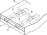
Fig. 6 is the perspective view of the liquid discharge head part of the embodiment of the invention after cut.
Fig. 7 A and 7B represent the operating process of movable part.
Fig. 8 represents the structure of the movable part and first fluid course.
Fig. 9 A, 9B, 9C represent the structure of the displaceable member and second fluid course.
Figure 10 A, 10B, 10C represent other form of displaceable member.
Relation between Figure 11 diagramming heating member area and the venting amount.
Figure 12 A and Figure 12 B represent the structural relation between displaceable member and the heating member.
Figure 13 diagramming from one side of heating member to the supporting-point of movable part distance and the relation the displacement of movable part.
Figure 14 represents the structural relation between movable part and the heating member.
Figure 15 A and 15B are the longitdinal cross-section diagrams by the liquid discharge head of another embodiment of the present invention.
Figure 16 is the driving pulse schematic diagram.
Figure 17 is by the typical supply of liquid discharge head of the present invention or the sectional view of feed path.
Figure 18 is the decomposition diagram of the present invention's one typical liquid discharge head.
Figure 19 is the decomposition diagram of a liquid discharge head box.
Figure 20 is the structural representation of a pumping equipment.
Figure 21 is the block diagram of device.
Figure 22 represents a discharge opeing register system.
Figure 23 A and 23B represent the structure of the fluid course of a traditional liquid discharge head.
After this will describe the present invention in conjunction with the accompanying drawings in detail.
The effect of the used movable part of the present invention will be described with reference to the drawings here, more particularly, will describe a kind of like this example here, wherein, improve the discharge opeing power and the efficient of discharge liquid by the direction of growth of control pressure conduction orientation of bubble and bubble.By the way, the following examples are described according to this prerequisite,, are expanded to the displacement region of movable part or the fluid course of foamed zones is disconnected from each other from feed tank that is.
Figure 1A is a cross sectional representation along the fluid course direction intercepting of the liquid discharge head that comprises a movable part to 1D.
In this liquid discharge head, heating element heater 2 (in the present embodiment, heating resistor is of a size of 40 μ m * 150 μ m), as the discharging energy generating element of thermal energy transfer being come discharge liquid to liquid, it is provided in the element substrate 1, is provided with a fluid course 10 over against heating element heater 2 on this element substrate 1.Fluid course 10 also links to each other with the common sap cavity 13 of giving a plurality of fluid course 10 supply liquid with leakage fluid dram 18, and therefore, the liquid supply that receives is suitable with the liquid that discharges from leakage fluid dram from common sap cavity 13.A movable part 31 that is plate shape has a planar section, and this movable part 31 is by elastomeric material such as metal, and it is positioned on the element substrate 1 and is cantilevers at fluid course 10, so that over against heating element heater 2.One end of this movable part is by the coating photosensitive resin or analog is fixed on the base portion (support member) 34 or on the analog that forms on the wall of fluid course 10 or in the described element substrate, thereby this movable part is maintained, and this just constitutes a strong point (support section) 33.
Heat by heating element heater 2 by the liquid in the foamed zones 11 that limits between movable part 31 and the heating element heater 2; According to as the film boiling phenomenon in U.S. No.4723129, described and in liquid, produce bubble.The pressure that is produced by foaming and the pressure preferential interaction of bubble itself are on this movable part, and this movable part shifts so that be that the center is unlimited greatly towards discharging oral-lateral with the strong point 33 shown in Figure 1B and 1C.According to transfer or its transfering state of movable part 31, the pressure that is produced by foaming is directed to the discharging oral-lateral, and the growth of bubble itself also is directed to this discharging oral-lateral.
Basic discharging principle when using above-mentioned movable part will be described in the back.One of most important principle in this discharge process is after the pressure that is produced by foaming or bubble itself causes that movable part shifts, movable part towards the bubble setting is transferred to the second place from the primary importance that is inactive state, by the movable part 31 after shifting pressure and bubble guiding itself is provided with the downstream of floss hole this moment.
This principle will be described clearlyer in conjunction with Fig. 2, and Fig. 2 represents not have traditional liquid flowing channel structure schematic diagram of movable part, and Fig. 3 represents the liquid flowing channel structure schematic diagram with movable part.Here, towards floss hole with use V respectively towards the direction of propagation of the pressure of upstream side
AAnd V
BExpression.
In traditional liquid discharge head shown in Figure 2, not having can be with the structure of restriction by the conduction orientation of the pressure of bubble 40 generations.Therefore, the pressure conduction orientation of bubble 40 is perpendicular to this bubble surface, as by V
1To V
8Represented.Has V
AThose pressure conduction orientation 1 of durection component are as V
1To V
4To fluid discharge is effectively, in other words, from half pressure conduction orientation of the bubble of bubble center towards floss hole.These pressure conduction orientation are very important, because they can directly be made contributions to analogues such as discharge opeing efficient, discharge opeing power, discharge opeing speed.Further, V
1The most close discharge opeing direction V
A, so it is the most effective.On the contrary, V
4V
ADurection component is just relatively little.
On the other hand, in the time of in using activity shown in Figure 3, movable part 31 will point to the pressure conduction orientation V of the bubble of each different directions in Fig. 2
1To V
4Be directed to downstream (discharging oral-lateral), convert them to pressure conduction orientation V
A, the pressure that is produced by bubble 40 directly works to discharging effectively whereby.Resemble pressure conduction orientation V
1To V
4The same, the growing direction of bubble itself also is directed to the downstream direction, thereby increases than big on updrift side at the downstream direction bubble.As mentioned above, by the growing direction of movable part control bubble, thus the pressure conduction orientation of control bubble, so discharge efficiency, discharge force, rate of discharge and analogue can fundamentally improve.
To the discharge opeing of the liquid discharge head that uses movable part be explained in detail to 1D with reference to Figure 1A.
Figure 1A represents the state before applying energy such as electric energy to heating member 2, that is, and and the state before heating member 2 produces heat.Here, this point is very important, that is, movable part 31 is provided at and make half position, its downstream at least that covers the bubble that is produced by heating element heater 2 heating.In other words, from this starting point of liquid flowing channel structure, movable part 31 extend in such a way than the regional center at least 3 of heating element heater more by downstream (than the regional center 3 by heating element heater and perpendicular to the line of fluid course length direction), that is, the downstream part of bubble will act on the movable part.
Represent to give heating element heater 2 to apply energy with 1B, as apply electric energy and produce the state of heat, the part of the liquid in foamed zones 11 has been heated, and bubble is produced by the boiling film.
Here, the pressure that is formed by the generation of bubble 40 makes movable part 31 shift from primary importance towards the second place, so that guides floss hole direction with the pressure conduction orientation of bubble.Here, as mentioned above, the free end 32 of movable part 31 is arranged on downstream (discharging oral-lateral), it is very important that its strong point 33 is arranged on upstream (common sap cavity), so that the part of movable part is in the face of the downstream part of heating element heater, the i.e. downstream part of bubble at least.
Fig. 1 C represents the states that bubble 40 further increases, and further is offset according to the pressure movable part 31 of bubble 40.The bubble that is produced than growing greatlyyer in updrift side, and surpasses the primary importance (position that is illustrated by the broken lines) of movable part at downstream direction.It is believed that the growth according to bubble 40, the transfer gradually by movable part can improve discharge efficiency, because the volume of pressure conduction orientation that moves and the bubble 40 that moves, in other words, bubble is grown towards free end, can finally be directed to floss hole.When being directed to the floss hole direction when bubble with by the pressure that bubble produces, movable part almost can not stop this propagation, therefore according to the intensity of pressure of being conducted effectively the controlled pressure conduction orientation and the bubble direction of growth.
Fig. 1 D represent when above-mentioned stop above-mentioned film boiling after because venting of the minimizing bubble 40 of bubble inner pressure power and the state that disappears.
Owing to bubble dwindles the negative pressure that forms and the flexible inlet restoring force of movable part itself, the movable part of transferring to the second place turns back to its initial position (primary importance) again shown in Figure 1A.Along with the disappearance of bubble, for the volume of bubble after the venting that replenishes foamed zones 11 and the volume after the discharge liquid, liquid is by upstream side B, that is, and and corresponding common sap cavity, liquid stream V
D1And V
D2, and from discharging oral-lateral, liquid stream V
CFlow to respective regions.
To describe in detail along with the operation of aforesaid foaming movable part and liquid releasing operation below and use refilling of liquid in the liquid discharge head of movable part.
Used the structure of the feed flow head of movable part will be with reference to the accompanying drawings 1A be described in further detail to 1D.
When the process shown in process Fig. 1 C, behind the maximum volume state, bubble 40 enters venting during the stage, the liquid volume amount suitable with the volume of bubble after disappearing enters foamed zones from first fluid course 14 of discharging oral-lateral, and enters foamed zones from common sap cavity 13 through second fluid course 16.In not having traditional liquid flowing channel structure of movable part 31, the liquid flowing resistance in the zone the amount of liquid from discharge opeing oral-lateral and common sap cavity side inflow to the bubble collapse position depends on from the foamed zones to the floss hole and from foamed zones to the zone the common sap cavity in liquid flowing resistance (based on the inertia of fluid course resistance and liquid).
Therefore, when when the flow resistance of discharging oral-lateral is hanged down, bubble position after a large amount of liquid is disappeared by the floss hole side inflow.Therefore the answer of meniscus becomes big.Especially, if by reducing to promote discharge efficiency near the flow resistance of floss hole, along with the disappearance of bubble, the answer of meniscus becomes bigger, therefore refills time lengthening, has suppressed high speed printing.
On the other hand, provide movable part 31 in the present embodiment, when this movable part turned back to its initial position along with the disappearance of bubble, the answer of meniscus rested on a bit, with the remaining lower part of bubble volume (ω
2) suitable liquid is mainly by the stream of the liquid in second fluid course 16 V
D2Supply.Here W represents the volume of whole bubble, W
1The volume of expression bubble on the primary importance of movable part 31, W
2The volume of the bubble of foamed zones 11 sides is stayed in expression.Therefore, the answer degree of the meniscus of traditional liquid discharge head approximates half of volume W, and meniscus answer degree is reduced to and is about volume W in the present embodiment
1Half, littler than the answer degree of meniscus in traditional liquid discharge head.
With volume W
2The negative pressure that suitable supply liquid is produced by the disappearance with bubble forces it mainly from the upstream side (V of second fluid course
D2) be guided along the surface of the movable part on the heating member side 31, therefore realize refilling faster.
In traditional liquid discharge head, when the negative pressure that produces when the disappearance that utilizes with bubble refilled, it is big that the chatter of meniscus becomes, and causes the reduction of image quality.On the other hand, press present embodiment, reduce greatly, because movable part has stoped the circulation between the liquid of the liquid of first fluid course, 14 discharging oral-laterals and foamed zones 11 at the chatter that refills at a high speed meniscus under the situation.
Possesses an above-mentioned movable part, when when record, using the discharge head of this band movable part, because liquid enters second fluid course 16 by fluid course 12 and is forced to refill foamed zones, so can refill fast, so can realize the discharging that repeats of stable fluid discharge, high speed, and can improve image quality and realize high-speed record, also can realize the answer of above-mentioned meniscus and the control of chatter.
Structure with movable part further comprises following useful effect, that is, and and along with foaming prevents pressure side (head sea) conduction upstream.
Because the pressure component on the bubble that produces on the heating element heater 21 is at these pressure components of major part (in the part of common sap cavity 13 sides) of bubble upstream portion, as the power (head sea) of liquid being pushed backward to upstream side.This head sea is pressed to the upstream with liquid, causes the motion of liquid and the inertia force that forms owing to liquid motion.These effects have reduced liquid and have entered refilling of fluid course, have suppressed high-speed driving.When using movable part, can suppress by this movable part 31 in these effects of upstream side, therefore, further improved the ability of refilling.
Further architectural characteristic and its effect of band movable part will be described below.
From liquid stream V
D1The liquid that is fed to foamed zones can be guided by a side (narrow slit 35) of movable part.; when using as Figure 1A to the big movable part of the whole foamed zones of the covering shown in the 1D (on the heating element heater surface); because of foaming to floss hole; for guide pressure more effectively, because of turning back to primary importance, movable part 31 becomes big in foamed zones 11 with near the flow resistance of the liquid between the floss hole zone in first fluid course 14.Like this, from liquid stream V
D1Liquid flow towards foamed zones 11 is hindered.In the liquid discharge head structure of using a kind of like this movable part, the liquid stream V of a high speed to foamed zones supply liquid arranged
D2, therefore, adopt this structure, promptly cover foamed zones 11 and can not reduce the liquid deliverability with this structure that realizes maximum discharge efficient with movable part 31.
For the free end 32 and the strong point 33 of movable part 31, this free end is positioned at than this strong point position in downstream more.This structure can play such effect promptly as mentioned above effectively, and when producing bubble, the pressure conduction orientation of bubble and its direction of growth are guided at the discharging oral-lateral.Further, this position relation is not only effective to discharge function, and also is effective to reducing the flow resistance that liquid flows through fluid course 10 when refilling with high speed.This is because this free end 32 and the strong point 33, when the answer meniscus turns back to floss hole 18 by capillary force when discharging, or when bubble collapse is supplied liquid, be arranged to not against flowing through fluid course 10, the liquid stream V of (comprising first fluid course 14 and second fluid course 16)
D1And V
D2
The additional description, at Figure 1A in 1D, the free end 32 of movable part 31 extends above heating member 2 so that more facing toward heating member 2 by the place in downstream than regional center 3, described regional center 3 is divided into the upstream region of heating member 2 and downstream area (one pass heating member regional center 3 (center) and perpendicular to the line of fluid course length direction) with heating member 2, movable part 31 can touch and more lean on pressure and the bubble that produces on the downstream than regional center 3 on the heating element heater whereby, and can go far towards the discharging of liquid, bubble and pressure are directed to floss hole, thereby can fundamentally increase discharge efficiency and discharge force.
In addition, the upstream portion of bubble also can play further effect.And the free end that is considered to movable part 31 passes through the mechanical bias of moment, can work to the discharging of liquid effectively.
Fig. 4 has described an embodiment who further strengthens fluid discharge power by above-mentioned mechanical bias.Fig. 4 is a cross-sectional view of describing this liquid discharge head structure.Described such a case in Fig. 4, promptly the free end of movable part is positioned at than heating member 2 position in downstream more.Such structure arrangement has increased the free-ended migration velocity of movable part, and has further increased the discharge force that the skew owing to movable part causes.
In addition, owing to compare with previous situation, the more close discharging oral-lateral of this free end so the growth of bubble can be focused on the more stable durection component, can be realized better discharging.
Although the migration velocity R of movable part 31
1Skew is directly proportional with the air bubble growth speed at pressure in bubbles center, but is positioned at than this point further from the free end 32 of the strong point 33 with higher speed R
2Skew, thereby so this free end 32 can act on the motion that causes liquid on the liquid with high speed machine ground, heat discharge efficiency.
When free-ended shape was flowed perpendicular to liquid, the pressure that is produced by bubble and the mechanism of movable part be discharge liquid more effectively.
The present invention can be made of the exhaust system of using the above-mentioned movable part of this use.The used discharge head of the present invention has structure, characteristics and the discharging principle of the discharge head that uses above-mentioned movable part, and except that these main elements, the present invention also has such characteristics, be that fluid course is divided into first fluid course and second fluid course, first liquid that is fed in first fluid course separates with second liquid that is used for foaming when heating that is fed to second fluid course.
Fig. 5 represents that the cross sectional representation of cutting along the liquid flow direction of the liquid discharge head of another embodiment of the present invention, Fig. 6 represent the perspective view of this liquid discharge head part after cut.
In the liquid discharge head of present embodiment, second fluid course 16 that is used for foaming is arranged on the top of the element body 1 that provides heating element heater 2, heating element heater 2 applies the heat that is used to foam to liquid, directly is set at the there with first fluid course 14 that floss hole 18 circulates mutually.
The upstream side of first fluid course 14 communicates with the first common sap cavity 15, is used for providing first liquid to many first fluid courses, and the upstream side of second fluid course 16 communicates with the second common sap cavity 17, is used for providing liquid to many second fluid courses.
Dividing plate 30 is made by elastomeric material such as metal, it is provided between first fluid course and the circulation of second liquid, and impenetrable liquid ground separates first liquid in first fluid course and second liquid in second fluid course, is not mixed in together so that make each other.
Be positioned at heating element heater surface wider space and (be called " blowdown presssure produces the zone " later on, zone A, and " foamed zones 11 ", area B, the part of dividing plate as shown in Figure 5) forms the movable part 31 that is cantilevered fashion, wherein forms free end in discharging O side (liquid downstream), and narrow slit commonly used 35, form a strong point 33 in common sap cavity (15, a 17) side.Because movable part 31 is over against foamed zones 11 (B), when foaming liquid foamed, first fluid course (shown in arrow among Fig. 5) is opened and entered to movable part 31 towards floss hole.In Fig. 6, dividing plate 30 also is positioned at and is inserted into a space on the element substrate 1 and forms second fluid course, and a heating resistor wherein is provided in the element substrate, as heating element heater 2, and provides a lead electrode 5 that is used for applying the signal of telecommunication to heating resistor.Be the mixing of two kinds of liquid preventing movable part free end and seam place, the width of finedraw should be to resemble to form a meniscus as described above between two liquid.In the present invention, this can realize by the characteristic of first and second liquid.The mixed of liquid at the movable part dual-side can prevent by adopting this structure, that is, make with the width of corresponding second fluid course of movable part littler than the width of movable part.In the present invention, this also can realize by the character of first and second liquid.
The strong point 33 of movable part 31 and the layout of free end 32 and with heating member 2 between position arrangement relation and aforementioned Figure 1A the same to shown in the 1D.
Position arrangement relation between fluid course 12 and the heating member 2 as mentioned above.In this embodiment, concern it also is like this with position arrangement between second fluid course 16 and the heating member 2.
7A and 7B describe the operation of present embodiment liquid discharge head below with reference to the accompanying drawings.When driving liquid discharge head, use first liquid that is fed to first fluid course 14 and second liquid that is fed to second fluid course 16 as foaming liquid.The heat that is produced by heating element heater 12 acts on the foaming liquid in the second fluid course foamed zones, produces bubble according to the film boiling phenomenon in foaming liquid whereby, as describe in the U.S. Patent No. 4723129.
In the present embodiment, blow pressure can not be escaped along other three directions except the updrift side of foamed zones, and therefore the pressure that produces with foaming is transmitted on the movable part 31 fully.Like this, when air bubble growth, movable part 31 is displaced to the zone of first fluid course shown in Fig. 7 B from the state shown in Fig. 7 A.By this operation of movable part, first fluid course 14 is communicated with greatly with second fluid course 16, so blow pressure is mainly propagated along the leakage fluid dram direction (direction A) of first fluid course.Above-mentioned mechanical bias first liquid by this pressure propagation and movable part is discharged from from leakage fluid dram.
At this moment, first liquid part and second liquid part can not be mixed in mutually together, but both are discharged from from leakage fluid dram as a droplet, described first liquid partly is arranged in the discharge opeing oral-lateral of first fluid course 14, and be discharged from from leakage fluid dram, described second liquid part is transferred to first fluid course, 14 1 sides from second fluid course 16.
Composition by purpose first liquid of the present invention and second liquid can suitably be chosen from the fluid composition with mutual not mixed nature, for example, a kind of another kind for hydrophobicity of first liquid and second liquid is the such composition of hydrophilic liquid.
The object lesson of the combination of these liquid can comprise some following combinations:
(1) water-based ink is as first liquid, nonpolarity solvent (as, cyclohexene or dimethylbenzene), perhaps the mixture of (silicone oil or the analog) of waterproof and non-phasic property solvent is as the composition of second liquid:
(2) oil-based ink is as first liquid, liquid, aqueous composition as second liquid.
As liquid, aqueous, can make the mixture of water or water and water-miscible organic solvent.As water-miscible organic solvent, for example, the common ink that can suitably use those in ink mist recording, to use.Object lesson comprises acid amides, for example dimethyl formamide and dimethylacetylamide; Ketone such as acetone; Ethers such as oxolane and dioxane; Polyglycols such as polyethylene glycol and polypropylene glycol; Alkylidene glycol such as ethylidene glycol; Propane diols, butanediol, triethylene glycol, thiodiglycol, hexylene glycol and diethylene glycol (DEG); The low alkyl ether of polyalcohol is as the ethylidene glycol monomethyl ether; Diethylene glycol (DEG) monomethyl ether and triethylene glycol monomethyl ether; Monohydric alcohol such as ethanol and isopropyl alcohol; 1,2,6 hexane triols (1,2,6-hexanetriol); Glycerine; N-methyl-2 pyrrolidones; 1,3-dimethyl-2-imidazolone; Triethanolamine; Tetramethylene sulfone; Dimethyl sulfoxide (DMSO); And cyclohexanol.These solvents can be used alone or be used with their any combining form.Water-miscible organic solvent composition in liquid can suitably be selected according to needed characteristic of liquid or analogue.They can contain from 1% to 80% percentage by weight.
Liquid, aqueously comprise various additives, as surfactant, the PH conditioning agent, anticorrisive agent, antioxidant, cosolvent and dispersant, they can use separately, also can use with their any combining form.To these additives, the surfactant that also can be used as surface tension modifier is preferentially used.These surfactants comprise anionic surfactant such as soap, high ethanol sulfate, alkylbenzenesulfonate and high ethanol phosphide salt; Cation surfactant such as aliphatic amine and quaternary ammonium salt; The ethylene oxide adduct of non-ionic surface activator such as high ethanol, alkyl epoxy ethane adduct, the aliphatic acid ethylene oxide adduct, many hydroxyls alcohol fatty acid ester ethylene oxide adduct, high alkylamine ethylene oxide adduct, the fatty acid amide ethylene oxide adduct, polypropylene glycol ethylene oxide adduct, many hydroxyls alcohol fatty acid ester and alkanolamine fatty acid amide; And amphoteric surface's activator such as amino-type and trimethyl ammonium lactone type both sexes activator.
Comprise pigment water-based ink can by above-mentioned liquid, aqueous in the dissolving or disperse a kind of dyestuff, pigment, dispersion toner or analog to obtain.Amount of pigment can be selected by desirable density of image, reactivity when being used as active element or analog when pigment., the amount of the percentage by weight that for example it can from 0.1% to 20% is used.As this pigment, also can use any pigment that uses in water-soluble resin or analog liquid, aqueous that is dispersed in.
The physical characteristic of liquid, aqueous or water-based ink can be regulated by selecting its component as viscosity and surface tension.
For oil-based ink, do not force any special restriction with regard to it as a Mo Eryan who in various printing processes, uses, the oil-based ink that obtains by dissolved oil soluble dye in the oil-dissolving solvent resembling dimethylbenzene or lytic agent so for example, and have the required characteristic of first liquid.
Then, movable part turns back to the position shown in Fig. 7 A when bubble is exitted, and in first fluid course 14, the relief liquor scale of construction suitable with being discharged from amount of liquid is from the upstream side supply.In this embodiment, the supply of discharge liquid is directed to the closing direction of movable part, as in the above-described embodiments, so discharge liquid refill the obstruction that can not be subjected to movable part.
When the main effect and the effect of relevant pressure conduction orientation of when foaming, with main effect and the effect along with the direction of growth of the relevant bubble of skew of movable part, and the effect that prevents head sea is with effect with describe equally at above-mentioned Figure 1A in 1D., use this embodiment of two liquid flowing channel structures further to have following advantage.
Promptly, the required thermal characteristics that foams does not require that first liquid has, therefore can loosen the design condition of first liquid greatly, because first liquid uses different liquid with second liquid, the drop of unmixed these liquid is discharged away by the pressure of the foaming generation of second liquid mutually.For example, even a kind ofly be difficult to by applying heat the high viscosity liquid that fully foaming does not have abundant discharge capacity, can be by supplying this liquid for first fluid course and giving a kind of liquid that is easy to foam of second fluid course supply [for example, the ratio of second alcohol and water is 4: 6 a mixture liquid (viscosity: be about 1 to 2cp)] or a kind of low foaming liquid as second liquid.
Further, as second liquid, it can select a kind of both having made also can not cause when bearing high temperature and resemble the such deposited liquid of coking on the heating element heater surface, thereby can realize the discharging that stable foaming is become reconciled.
Further, because discharge head structure of the present invention also can be brought above-mentioned effect, therefore the liquid as high viscosity liquid so still can be discharged with maximum discharge efficient and discharge force.
Further, even a kind of liquid that is easy to be influenced by heat can be discharged with maximum discharge efficient and discharge force, as mentioned above, only by this liquid is supplied to first fluid course, and supply a kind of heat-resisting liquid that is easy to bubble for second fluid course, and can not reduce its quality owing to being heated.
The embodiment of liquid discharge head major part of the present invention and fluid-discharge method has been described above.The back will be described with reference to the drawings the preferred structure that is used for these embodiment.
Fig. 8 be by in one embodiment of the invention along the liquid discharge head cross-sectional view of fluid course direction intercepting, the trough of belt spare 50 that provides a groove and limit first fluid course 14 (or Figure 1A is to fluid course shown in the 1D 10) is provided on the dividing plate 30.In this embodiment, near the top of this fluid course the movable part free end 32 is raised, therefore can make the operation angle θ of movable part bigger.Because this structure of fluid course, the life-span foaming capacity of movable part and the opereating specification of analogue movable part can be determined., ideal situation is that movable part forwards an angle of the discharging angle that comprises vertically to.
The diameter of the offset height brake specific exhaust emission mouth of movable part is higher, as shown in Figure 8, therefore can realize the abundant transmission of discharge force.In addition, since with the overhead height of the fluid course of the movable part strong point 33 corresponding positions than low with the overhead height of the fluid course of movable part free end 32 corresponding positions, such as shown in Figure 8, the escape at the pressure wave of upstream example that is caused by the skew of movable part can be prevented effectively.
Fig. 9 A represents the variation of position arrangement relation between second fluid course 16 and the movable part 31 to 9C.Fig. 9 A is the top plan view of movable part 31 adjacent domains.Fig. 9 B represents movable part 31 is removed the top plan view of back second fluid course 16, and Fig. 9 C is placed on movable part 31 that the position between the movable part 31 and second fluid course 16 concerns schematic diagram on second fluid course 16.In these all figure, the bottom of each figure is the front side that leakage fluid dram is set.
In traditional liquid discharge head, the runner and the discharge opeing runner of guiding foaming are same runners, Road narrows partly are provided at common sap cavity side, so that preventing the pressure of feed liquor body cavity escapes from common sap cavity, it is necessary adopting such structure, promptly fully takes into account refilling of liquid at the cross-sectional area of the runner of Road narrows parts and is not too little.
Can be in the present embodiment, the most of liquid that is discharged is supplied to first fluid course as first liquid, therefore the consumption of second liquid (foaming liquid) in second fluid course of heating element heater is provided is compared greatly with first liquid and is reduced, and can save the amount of refilling of the foaming liquid that enters the foamed zones in second fluid course.Therefore, the space of Road narrows part 19 can be made from several microns so narrow to tens microns, so that can prevent further that the pressure that produces along with foaming from running away in second fluid course around, thereby can more fully pressure be directed to movable part, can be used as discharge force by movable part 31 in order to reach higher this pressure of discharge efficiency., the form 2 of second fluid course 16 only limits to said structure, and it can adopt any form as long as it can more effectively pass to the movable part side with pressure with the generation of bubble.
Shown in Fig. 9 C, the both sides of movable part 31 all cover the part of the wall that constitutes second fluid course, therefore can prevent that movable part from falling into second fluid course.This can guarantee that when not discharging first liquid in first fluid course and second fluid separation applications in second fluid course are opened.By this structure, can prevent bubble from the narrow slit escape, therefore can further increase discharge force and improve discharge efficiency.Further, this also can strengthen aforesaid when bubble collapse, based on the refill effect of the negative pressure that is produced from upstream side.
In Fig. 7 B and Fig. 8, when movable part 31 during to the skew of first fluid course 14, the part of the bubble that produces in the foamed zones of second fluid course 4 extends in first fluid course 14.When the height of second fluid course can make that bubble extends in first fluid course, comparing with the inductile situation of bubble further to increase discharge force.For bubble is extended in first fluid course 14, make that preferably the height of aspect ratio largest air bubbles of second fluid course is little, from several microns in 30 micrometer ranges.In the present embodiment, this highly is 15 μ m.
Figure 10 A has described other form of movable part 31 to 10C.Narrow slit on the mark mark 35 expression dividing plates.This narrow slit has been determined movable part.Figure 10 A represents a rectangular form, and Figure 10 B represents to be easy to the form that strong point side has neck down portions that operates in of movable part, and Figure 10 C represents in order to increase its life-span has wider portion in strong point side form.For easy operating and life-span longer, shown in Fig. 9 C, determine that by two circular arcs the form of a neck is desirable in strong point side., can adopt any type of movable part, as long as movable part can not fall into second fluid course, and easy operating, long getting final product of life-span.
Among the embodiment in front, tabular movable part 31 is to be made by the thick nickel plate of 5 μ m with the dividing plate 5 that has this movable part, but the present invention is not limited to this.The material that is used for movable part and dividing plate can be any material, as long as they have high antilysis to liquid contacted with it, and has movable part successfully to operate necessary elasticity to get final product, and a finedraw forms in them.
Consider from this starting point of high life, the preferred example of movable part material comprises, metal as silver, nickel, gold, iron, titanium, aluminium, platinum, tantalum, stainless steel and phosphor bronze and their alloy, the itrile group resin comprises acrylonitrile, butadiene, styrene or analog, amide groups resin such as polyamide, carboxy resin, as Merlon, formaldehyde-based resin such as aldehyde resin, the resin as liquid crystal polymer and their composition.Consider from high ink-resistant property this point, comprise as gold, tungsten, tantalum, nickel, stainless steel and titanium and the such metal of their alloy, and those are coated with the material that is coated with these metals, the amide groups resin, as polyamide, formaldehyde-based resin such as aldehyde resin, ketone-based resins is as poly-(arbitrary ketone), imido grpup resin such as polyimides, hydroxy resin such as phenolic resins, ethylamide resin such as polyethylene, alkyl resin such as polypropylene, epoxy resin-matrix resin such as epoxy resin, amino resins such as melmac, and their composition, pottery as silica and their composition.
The preferred example of separator material comprises having good thermal resistance, active and the plastic material of resistance, engineering plastics in the last few years are representative, as polyethylene, polypropylene, polyamide, the polyethylene terephthalate ester, melmac, phenolic resins, epoxy resin, polybutadiene, poly-argon carbamate, poly-(ether ether ketone), poly-(ether sulfone) polyarylate, polyimides, polysulfones and liquid crystal polymer (LCP), and their composition, silica, silicon nitride, metal and as nickel, gold, stainless alloy and their composition and being coated with is coated with the material of titanium or gold.
Consider as its used material of a dividing plate and reach the high strength required form, and, can determine the thickness of dividing plate as the good operability of a movable part., ideal situation is in 5 to 10 mu m ranges.
In this embodiment, the width that limits the narrow slit 35 of movable part 31 is 2 μ m., but its width appropriate change, only otherwise the effect that the destructive activity part is provided gets final product.For example, this width preferably is controlled in 5 μ m or littler, more preferably 3 μ m or littler.Among the present invention, first liquid and the isolation between second liquid that are fed to respectively in first fluid course and second fluid course that are separated by movable part and dividing plate are to guarantee by the characteristic of selecting these liquid.The width of narrow slit can be conditioned, so that these liquid can form a meniscus, therefore can guarantee to separate more reliably.
Among the present invention, plan to allow movable part have the thickness (t μ m) of μ m level rather than thickness with cm level.When the finedraw of μ m width (ω μ m) is intended for use to have the movable part of μ m level thickness, is preferably in and considers the production deviation to a certain extent.
(Fig. 7 A and 7B when equaling the thickness of movable part facing to movable part free end and/or its edge and thickness that center on the next door layer of its formation finedraw, and Fig. 8), can regulate the thickness of finedraw width and movable part and be prevented from better by in following ranges, considering manufacture deviation at mixed (the no emissions operation) of two kinds of liquid of inactive state.When high viscous ink (5cp, 10cp, etc.) is 3cp or the second lower liquid when using with viscosity, concern more that by satisfying w/t≤1 can prevent the mixed of two kinds of liquid in long a period of time, this is maximum conditions of this liquid discharge head structure.
As once the narrow slit that only can reach " a basic closed condition " of the present invention by the structure of liquid discharge head, several micron-sized narrow slits just can guarantee this state., by utilizing different characteristics of liquids of the present invention just can loosen this condition.
As mentioned above, this movable part can be used as the part of the separator of first liquid and second liquid.When skew took place this movable part when foaming, a part second liquid in second fluid course entered first fluid course, thereby formed one by being in and mutual not first liquid of mixed state and the discharging drop that second liquid is formed.The ratio of component of these liquid that are used to form image in the discharging drop can suitably be selected according to the structure of liquid discharge head and analog.In order to show a kind of like this feature, the required heat that promptly foams can be lowered greatly, yet preferably the ratio of first liquid is high as much as possible in the scope that allows the realization objects of the present invention.Preferably modulated in advance by this way, promptly the shared ratio of first liquid and second liquid is in the scope as 50: 50 to 95: 5.And preferably preset the concentration of pigment by first liquid and the shared ratio of second liquid.
For example, also can control first liquid and the shared ratio of second liquid at the drive condition of the heating member of foamed zones by change.This this situation of control method consideration is described.That is first, the liquid, aqueous liquid mixes with second liquid that is discharged.This method also is applicable to method of the present invention, that is, preferably two kinds of liquid exist simultaneously when discharging and express certain gradation.
With reference now to accompanying drawing, the relation of the position arrangement between the heating element heater and movable part in this liquid discharge head is described.Yet the form of movable part and heating member, size and quantity are not limited to following situation.The pressure that makes liquid arrange effectively heating element heater to be made liquid foam produce by the optimum position of heating member and movable part is used as blowdown presssure.
In discharge opeing recording method prior art, the recording method of so-called spray bubble, wherein be applied in the China ink the energy as heat by in the China ink rapidly Volume Changes cause the variation of the state of following, by the operational forces that produces by this state variation China ink is discharged from floss hole and to be applied on the recording medium, thereby form an image, as shown in Figure 11, between the discharge capacity of the area of heating member and China ink a proportionate relationship is arranged., found that a foaming is to the inoperative inactive area S of venting.And found also that from the condition of burning on heating element heater the inactive area S that foams is present in the periphery of heating element heater.The peripheral part of the about 4 μ m width of heating element heater does not participate in foaming as can be known from these results.
Therefore, we we can say the pressure that produces with foaming in order to effectively utilize, and arranging movable part by this way is effectively, promptly, the zone of action covers just in time the space above the effective coverage of heating element heater foaming, and this zone is from its periphery zone of at least 4 μ m inward.Among the present invention, the effective coverage of foaming is confirmed as from its periphery zone of μ m at least inward, but the present invention is not limited to this, but depends on the kind and the formation method of heating element heater.
Figure 12 A and 12B are the schematic top plan view of the heating member of 58 * 150 μ m and side's placed on it movable part 301 (Figure 12 A) and 302 (Figure 12 B).301 and 302 zone of action is different each other.
From top result be appreciated that movable part preferably be arranged to cover just in time be the foaming effective area on this area, consider this life-span and discharge efficiency, the area of movable part is bigger than the area of heating member.
Figure 13 is the schematic diagram that concerns expression skew of movable part and the distance from the movable part fulcrum to the heating member edge 1.Figure 14 is the position relation between movable part 31 and the heating member 2 is seen in statement from side direction a cross section calcspar.The size of employed heating member is 40 * 105 μ m.People can see, when the distance to the fulcrum of movable part 31 1 was elongated from the edge of heating member 2, skew became bigger.So ideal situation is, the position of the fulcrum of movable part is by according to the form of the circulation road structure of required lifting rate discharge opeing and heating member and definite optimized migration is determined.
When the fulcrum of movable part just in time was positioned on effective foamed zones of heating member, except that the stress that the skew by movable part produces, the pressure that is produced by foaming directly put on the fulcrum, thereby has reduced the life-span of movable part.Inventor of the present invention tests, and the result shows at fulcrum and just in time is arranged in the liquid discharge head of foaming on the effective coverage, applies 1 * 10
6Individual pulse removable wall is just destroyed, has therefore reduced its life-span.So when the fulcrum of movable part was positioned at the position that does not just in time face toward the foaming effective coverage, even the form of movable part and material make its life-span not high, it also can be actually used.On the other hand, just in time be positioned on the foaming effective coverage,, also can successfully utilize this movable part by selecting its shape and material even work as fulcrum.In a kind of like this structure, can provide a liquid discharge head with durability of maximum discharge efficient and excellence.
Below description is provided the structure that applies the element substrate of hot heating element heater to liquid.
Figure 15 A and 15B are the longitudinal cross-section schematic diagrames of describing liquid discharge head, and one provides the diaphragm that will more describe subsequently, and one does not have diaphragm.
On element substrate 1, be disposed with second fluid course 16, dividing plate 30, the first fluid courses 14 and the trough of belt spare 50 that is used for limiting first fluid course that has groove.
This element substrate 1 comprises the substrate 107 of being made by materials such as silicon.In this substrate, be disposed with in order to insulate and the silica or the silicon nitride film 106 of heat accumulation, the thermal resistor layer of making by hafnium boride, tantalum nitride or calorize tantalum 105 that constitutes heating element heater (thickness: 0.01 to 0.2 μ mP), lead electrode 104 made of aluminum or pattern as shown in Figure 6 (thickness: 0.2 to 1.0 μ m).Apply voltage for resistor layer 105 by two lead electrodes 104 and make electric current pass through resistor layer, thereby produce heat.On the resistor layer between two lead electrodes; form thickness and be the protective layer that is formed by silica, silicon nitride or analog of 0.1 to 2.0 μ m, further formation protects this resistor layer 105 to avoid anti-cavitation layer (thickness: 0.1 to 0.6 μ m) as various corroded by liquid such as China inks by forming analog thereon.
Especially, the pressure of the vibration wave that produces with the foaming or the disappearance of bubble is strong, and it reduces the life-span of not only hard but also crisp sull greatly.Therefore, tantalum (Ta) or the similar material as metal material is used as anti-cavitation layer.
According to the combination of liquid, liquid flowing channel structure and resistor material, this liquid discharge head can have the structure that does not need above-mentioned protective layer.This structure is shown in Figure 15 B.The examples of material that is used for this resistor layer without any need for protective layer comprises iridium-tantalum-aluminium alloy and analog.
As mentioned above, the heating member among above-mentioned each embodiment can also can and be used for protecting its protective layer to constitute by resistor layer only by the resistor layer between the electrode (heating part formation).
In this embodiment, have by what resistor constituted and can be used as heating member according to the heating element heater that the signal of telecommunication produces the heating part of heat, can the present invention is not limited to this.Any heating element heater all may be utilized, as long as it can foam in second liquid as expanding foam solution, is to get final product with the discharging relief liquor.For example, have, or have the heating element heater of the heating part that produces by high frequency by the heating element heater of using up the heating part of forming as the photothermal converter of laser generation heat.
Except electrothermal transducer of forming by the resistor layer 105 that constitutes above-mentioned heating part and the lead electrode that is used for to the resistor layer transmission of electric signals, be used for driving selectively the function element of electrothermal transducer, as triode, diode or mobile resistance, can prepare by integral production in the said elements substrate by semiconductor production process.
For thereby the heating part discharge liquid of the electrothermal transducer that provides in aforesaid this element substrate 1 is provided, by lead electrode 104 this rectangular pulse as shown in figure 16 is added on the aforesaid resistive layer 105, thereby causes that the resistive layer 105 between lead electrode produces heat rapidly.In each discharge head of above-mentioned each enforcement, be 24V by applying a voltage, pulse width 7 μ sec, electric current are that 105mA, frequency are that the signal of telecommunication of 6KHZ drives heating element heater, thus this as described above operation is discharged liquid ink from floss hole., the situation that drives signal is not limited only to this, can adopt any driving signal, as long as it can make foaming liquid fully bubble.
To describe a typical structure of liquid discharge head below, this liquid discharge head can successfully import the first and second common sap cavities with different types of liquid and they do not mixed, and can reduce number of components, reduces production costs.
Figure 17 is a cross sectional representation of describing this structure of liquid discharge head.
In this embodiment, trough of belt spare 50 roughly is made up of pinhole plate 51, this pinhole plate 51 has floss hole 18, be used for correspondingly limiting a plurality of grooves of many first fluid courses 14, and be used for limiting and a plurality of fluid course 14 intercommunication liquid and the trough of belt part of giving the first common sap cavity 15 of each first fluid course, 14 supplies, first liquid.
This first many fluid course can be defined by the bottom that dividing plate 30 is welded on trough of belt spare 50.Such trough of belt spare 50 has first a liquid service duct 20 that extends to the first common sap cavity 15 from its top.In addition, trough of belt spare 50 has second a liquid service duct that extends to the second common sap cavity 17 from its top by dividing plate 30.
As shown by arrow C, first liquid is fed to the first common sap cavity 15 by the first liquid service duct 20, then to first fluid course 14, simultaneously, shown in arrow D, second liquid is supplied to the second common sap cavity 17 by the second liquid service duct 21, then to second fluid course 16.
In this embodiment, the second liquid service duct 21 is parallel with the first liquid service duct 20, yet the present invention is not limited to this.It can be configured to any way, if it be limited or be passed in dividing plate 30 that the first common sap cavity, 15 outsides provide and with second common sap cavity 17 intercommunications.
The thickness of the second liquid service duct 21 (diameter) can be determined according to the feed speed of second liquid.The form of second liquid supply passage 21 needn't be rounded, and it can be rectangular.
Can come dividing strip slotware 50 by dividing plate 30, form the second common sap cavity 17.As a forming process, get like that described in the decomposition diagram of present embodiment as shown in figure 18, form common sap cavity framework and one second fluid course wall by the dry film on the element substrate, the assembly of trough of belt spare 50 and dividing plate 30 fixed thereon is welded on the element substrate 1, thereby can form the second common sap cavity 17 and second fluid course 16.
In this embodiment, element substrate 1 is set on the metallic substrates 70 as aluminium, provides many electrothermal transducers as heating element heater in element substrate 1, and they can produce heat, by as above on film boiling cause foaming and produce bubble.
Be arranged on the substrate 1 is many grooves that are used for limiting second fluid course 16 that is formed by the second fluid course wall, one is used for being defined for the sunk part to the second common sap cavity (common foaming sap cavity) 17 of each foaming liquid passage supply foaming liquid, and the demarcation strip 30 that provides the movable utmost point 31.
For the position arrangement relation of 50 on element substrate 1, dividing plate 30 and trough of belt top board, each movable part 31 can be arranged to the heating element heater on the element substrate 1, and first fluid course 14 is configured to relative with movable part 31.In this embodiment, the embodiment that one second service duct is set has been described in trough of belt spare., the feed speed according to second liquid can provide many second feed paths.First feed path 20 is directly proportional with corresponding feed speed with long-pending can being confirmed as of the flow channel cross-section of foaming liquid feed path 21.The part and the like that constitute trough of belt spare 50 can make its miniaturization by the cross-sectional area of preferred these circulation roads.
According to this embodiment, as mentioned above, first service duct of supplying second service duct of second liquid and supplying first liquid for first fluid course to second fluid course forms towards the trough of belt top board inside as a trough of belt spare, thereby can reduce the quantity of parts, can shorten production process and can reduce cost.
In addition, passed through second service duct along the direction guiding that passes dividing plate for second liquid of the second common sap cavity supply that communicates with second fluid course, described dividing plate separates first liquid and second liquid, thus with dividing plate, trough of belt spare and the substrate that forms heating member on it mutually step welded together can finish at one time.Therefore, be easier to produce, also can add the accuracy of strong weld, so just can discharge relief liquor reposefully.
Further, because second liquid is supplied to the second common sap cavity by dividing plate, second liquid can be fed to second fluid course reliably, thereby can guarantee enough supply rates, realizes stable discharging.
Among the present invention, as described in the embodiment in front, the structure with above-mentioned movable part allows than traditional liquid discharge head with higher discharge force, faster speed discharge liquid.
Roughly describe now by the liquid discharge head box that liquid discharge head is installed on its of the foregoing description.
Figure 19 is the schematic exploded perspective view that comprises the liquid discharge head box of above-mentioned liquid discharge head.This liquid discharge head box mainly comprises liquid discharge head part 200 and liquid container 90.
Liquid discharge head part 20 is to supply with part 80, bottom 70 and analog by element substrate 1, dividing plate 30, trough of belt spare 50, Pressure-bar spring 78, liquid to constitute.On element substrate 1, provide many aforesaid number rows heating resistor and many function element that drives heating resistor selectively to the foaming liquid heating.In element substrate 1 with have between the aforementioned barriers 30 of portable plate and define the expanding foam solution circulation road, foaming liquid flows through this passage.Determine by dividing plate 30 is welded on the grooved top plate 50 by its relief liquor circulation road (not shown) that flows through discharge liquid.
Pressure-bar spring 78 is one to be used for applying the element of bias force for trough of belt spare 50 to element substrate 1 direction.By being connected on the pedestal 70 with regard to a bias force, this will describe subsequently well for element substrate 1, dividing plate 30 and trough of belt spare 50.
Liquid container 90 is equipped with two kinds of liquid that will be fed on the liquid discharge head respectively.Provide in the outside of liquid container 90 and to be used for installing one this container is connected to the keeper 94 of connector of liquid discharge head and the fixed axis 95 that is used for fixing this connector.First liquid that is supplied in first fluid course is supplied by the service duct 92 of liquid container 90, the service duct 84 that passes connector enters the feed path 81 that liquid is supplied with part 80, and the service duct 83,71,21 by each element is supplied to the first common sap cavity.Second liquid (expanding foam solution) also is to be supplied with by the service duct 93 of liquid container 90, and the service duct that passes connector enters the service duct 82 of liquid delivery member 80 and the service duct 84,71,22 by each element is supplied to the second common sap cavity.
When depleted liq, can be by refilling corresponding liquid for the liquid container and reusing again.Therefore be preferably in the liquid inlet is provided in the liquid container.Further, liquid discharge head and liquid container both can wholely form mutually, also can form respectively.
Figure 20 is a schematic diagram of describing the pumping equipment structure, and above-mentioned liquid discharge head wherein is installed.Balladeur train HC is equipped with one and removably provides the liquid discharge head box of a liquid container part 90 and liquid discharge head part 200, and can move back and forth along the width of the recording medium as record-paper 150.Described recording medium is transmitted by a recording medium conveyer.
When applying a driving signal from unshowned driving signal supply device to the pumping equipment on balladeur train, with this signal response, first liquid and second liquid are admixture and emit from liquid discharge head.
The pumping equipment of present embodiment has a motor 111 as drive source, and it is used for activation record media delivery apparatus, balladeur train gear 112,113 and balladeur train axle 115, sends kinetic energy to balladeur train or similarity piece from drive source.The fluid-discharge method of realizing by this tape deck with by this tape deck on various recording mediums, thereby just can improve the printed matter with high quality graphic with fluid discharge.
Figure 21 describes to be used for using fluid-discharge method of the present invention and liquid discharge head and to carry out the operation of the whole device of venting record.
Tape deck receives printing information as control signal from main frame 300.This printing information is temporarily stored in the input interface 301 of printing in (tape deck), but meanwhile converts it into deal with data in this tape deck and be input among the CPU302 that merges mutually with the device of supplying liquid discharge head driving signal again.CPU302 handles the input data and is translated into printed data (view data) according to the peripheral unit of control program utilization as RAM304 that is stored among the ROM303.
For the appropriate location on record-paper printing image, CPU302 also produces driving data, is used for driving and the view data CD-ROM drive motor of moving recording paper and record head synchronously.View data and motor driving data respectively by head driver 307 and motor driver 305 control be transmitted opportunity to the end 200 and CD-ROM drive motor 306 in, form an image thus.
The recording medium that can be used for aforesaid this tape deck comprises various paper, OHP paper, the plastics that are used for compact disc and decorative panel, cloth, the metal material as aluminium and copper, resembles the such leather substance of ox-hide, pigskin and leatheret, timber as wood, glued board, bamboo, as watt pottery, and three-dimensional structure resemble the sponge.
Above-mentioned tape deck is included in the printing machine that various paper and OHP open the enterprising line item of paper, plastics tape deck at the enterprising line item of plastics as high density disk, metal tape deck at metallic plate or the enterprising line item of thin plate, leather tape deck at the enterprising line item of leather, timber tape deck at the enterprising line item of timber, at the ceramic tape deck of the enterprising line item of ceramic material, at the tape deck of the enterprising line item of three-dimensional structure and at the textile printing device of the enterprising line item of cloth resemble the sponge.
For the discharge liquid of using in these pumping equipments, can use the liquid that has characteristic of the present invention at least and be suitable for corresponding recording medium and record condition.
To describe a typical venting register system now, liquid discharge head wherein of the present invention is used as the record head of the enterprising line item of recording medium.
Figure 22 is a structural representation of describing the venting register system of using liquid discharge head 201 of the present invention.Liquid discharge head in the present embodiment is a solid line type record head, all provide many and be separated by 360 on each head, and with the corresponding length of record width of recording medium 150 in floss hole.Four statures of yellow, pinkish red, blue, black four kinds of colors by a clamper 202 along directions X with preset space length in parallel to each other fixed support get up.
From constituting the head driver 307 that drives signal supply device signal is fed to respectively these heads, thereby drives corresponding head according to these signals.
Give the China ink of these supply Huangs, magenta, blue, black four kinds of colors correspondingly from ink container 204a to 204d.By the way, mark mark 204e represents to be equipped with the expanding foam solution container of second liquid (foaming liquid), and its formation can make this expanding foam solution be fed to each stature from this container.
Below each stature, provide the head cap 203a that the blotting material is housed in it to 203d.When not carrying out record head, these caps are lived the floss hole of corresponding head, thereby these can obtain maintenance.
306 expressions of mark mark constitute the conveyer belt of conveyer, and it is used for being transmitted in describes various recording mediums among the embodiment of front.This conveyer belt 206 is walked around predetermined passage by various rollers stretchings and is driven by the driven roller that links to each other with motor driver 305.
In pressing the venting register system of present embodiment, the pretreatment unit 251 and the after-treatment device 252 that carry out various processing before and after record correspondingly are provided at upstream side and the downstream that recording medium transmits passage.
The content of preliminary treatment and post processing changes according to the kind of the recording medium that writes down thereon and the kind of employed China ink.For example, for metal, plastics and the such recording medium of pottery, preliminary treatment is that they are exposed in ultraviolet and the ozone to activate its surface, can improve their absorbency thus.Be easy to the medium of static electrification, as plasticity, because static being easy at its surface absorption dust.In some cases, high quality record will prevent the infringement of dust.Therefore, preferably to remove static on the recording medium,, thereby get on except that dust from recording medium as preprocessing process by ionizer.Consider that prevention China ink is dirty or improve the location look, need be to applying a kind of material of from alkaline matter, water-soluble substances, synthetic polymer, water-soluble metal salt, urea and thiocarbamide, selecting on the cloth, and as preprocessing process.Preliminary treatment is not limited to above-mentioned these processing procedures.As a kind of preliminary treatment, the temperature of recording medium will be controlled as the temperature of suitable record.
On the other hand, post processing is included as the photographic fixing processing that the recording medium that applies China ink is convenient to the photographic fixing of China ink, as heat treatment or be exposed in the ultraviolet, and for remove in preprocessing process, apply but the cleaning treatment of not reacted inorganic agent under the residue.
In the present embodiment, the solid line head is described, but the present invention is not limited to this, this device also can be to constitute like this, thereby promptly aforesaid small records head moves along the width of recording medium and carries out record.
The present invention will more specifically be described in conjunction with following Example in the back.By the way, all " part " of using in the following example or " n part " expression parts by weight, unless stated otherwise.Example comprises by the general molecular formula for 1: three part
 In the cyclohexane that the ethane silicone oil adding of the composition of n:0~1000 expressions is 97 parts, it is as nonpolarity solvent, and preparation is supplied to second liquid as foaming liquid in second fluid course.
Prepare water-based ink by methods known in the art by following compositions, thereby first liquid that is supplied in first fluid course is provided.(composition of water-based ink)
C.J. food is black 25 parts
10 parts of glycerine
10 parts of diethylene glycol (DEG)s
75 parts in water
The mixed liquid of first liquid and second liquid is used to have as described in Figure 5 by having installed that the device of the liquid discharge head of structure carries out the discharge opeing record, being 90: 10 being discharged first liquid in the drop each time to the volume ratio of second liquid wherein, is the printing sample of 1 * cm so that obtain the solid printing area on level and smooth paper.
Each drop that the analysis showed that to the document image of such acquisition has a kind of like this structure, that is, second liquid that is discharged covers first liquid drop, in other words, is coated with a kind of structure of second liquid on the round dot of first liquid.Comparative example 1:
Only make in the use-case 1 water-based ink of using, that is, this water-based ink is supplied with first fluid course and second fluid course, and carries out the discharge opeing record identical with example 1, obtains printing sample thus.Characterization test agent 1:
Image on the printing sample that example 1 and comparative example 1 are obtained carries out the Test Identification of following items.1) durability:
The image-side of each printing sample towards and tilt with 45,1ml water drips on it along this mode that image-side slides with water droplet, observes thus colored liquid stream whether to occur.Found that and on the printing sample of example 1, almost do not observe colored liquid stream.On the other hand, on the printing sample of comparative example 1, observe colored liquid stream.The printing sample of this sample 1 has good water proofing property.2) image gloss
With the naked eye identify the gloss of each printing sample.As a result, find to compare with the printing sample of comparative example 1 printing sample of example 1 makes moderate progress on gloss.3) rub resistance:
To prepare a printing sample with the same mode of example 1, remove the pigment difference, it is black 2 to use color pigment to replace C.I. food at this, thus the rub resistance that is improved.Identify the friction level of image for 5 times with the print surface of this printing sample of erasing rubber.As a result, to this printing sample without any problem.On the other hand, the printing zone of comparative example 1 printing sample fades.Example 2:
Prepare first liquid (water-based ink) that will be supplied in first fluid course by following ingredients.(first liquid component)
Disperse toner
*) 50 parts
10 parts of diethylene glycol (DEG)s
10 parts of glycerine
30 parts in water
*) with 10 parts of MCF88 (trade name, the commodity of Mitsubishi Kagaku), 10 parts of styrene-propene copolymer resins (molecular weight: 8000, Seiko chemical industry Co., Ltd) and 80 parts of water mix and make the dispersion toner.
As first liquid, cyclohexane give is second liquid with water-based ink, by carrying out the discharge opeing record with the used same device of example 1.At this moment, thus be added on the heating element heater volume that changes the each discharging of decision drop with the electric pulse condition of recorded information response variedly.As a kind of adjusting, only use first liquid, in other words, the liquid that is fed in first fluid course and second fluid course is water-based ink, carries out and aforesaid identical discharge opeing record.Found that when using water-based ink and cyclohexane, compare that each discharging drop and volume increase about 10% under same impulsive condition with the situation of only using water-based ink.
The pulse signal that under the identical condition of discharge volume, compares these situations.Found that when using water-based ink and cyclohexane compare with the situation of only using water-based ink, pulse signal intensity is less.
As discharge liquid, second liquid prevents the variation of relief liquor characteristic as the fluid-discharge method of the present invention of foaming liquid and the consumption that liquid discharge head can reduce second liquid greatly, can keep suitable fluid discharge like this in longer a period of time with first liquid.Further according to the present invention, can form the drop that not only comprises first liquid but also comprise second liquid, first and second liquid effect separately can be illustrated on the recording medium as paper and liquid receiving layer.
As mentioned above, be supplied to the liquid of foamed zones and not by foamed zones or in discharge head in the activity liquid of offset area guarantee their released state by the difference of character between these liquid.The functional separation of so further these liquid of increasing just can further increase the advantage that the use by two kinds of liquid brings.
Further, when selecting above-mentioned two kinds of mixtures of liquids suitably, just can obtain the record of light, high-quality and waterproof.In addition, can more effectively prevent the floss hole place thickening and the fouling of head.In addition, final document image has good glossiness.
Although the present invention is described according to present imputed preferred embodiment, be appreciated that these embodiment that the present invention is not limited to disclose.On the contrary, present inventor's included various distortion and equality unit in covering additional claim scope.Scope to following claim has given the wideest explaining, so that comprise all these distortion and equivalent structure and function thereof.
Claims (41)
1, a kind of fluid-discharge method comprises step:
One liquid discharge head is provided, comprises:
One leakage fluid dram;
One comprises the first area of first liquid;
One comprises the foamed zones of second liquid, and bubble produces in this second liquid, and
One has the movable part that a free end and is positioned at the support section of this free end upstream side, when producing bubble in second liquid in foamed zones, this movable part can be displaced in the first area the second place away from foamed zones from the primary importance that covers foamed zones, and skew is directed to leakage fluid dram at the movable part of the second place with the bubble in the second area; And
From leakage fluid dram discharging at least the first liquid, it is characterized in that first and second liquid are incompatible each other.
2, a kind ofly it is characterized in that free end is arranged on than the regional center of the heating element heater place in downstream more concerning liquid stream according to the described fluid-discharge method of claim 1.
3, a kind ofly it is characterized in that when skew took place movable part, the part of the bubble that is produced was extended to first fluid course according to the described fluid-discharge method of claim 1.
4, a kind of fluid-discharge method as claimed in claim 1 is characterized in that, formed bubble contacts with the movable part that is being offset during the movable part skew.
5, a kind ofly it is characterized in that described bubble is the bubble that the film boiling phenomenon that causes by passing to the heat of liquid from heating element heater produces by one of any described fluid-discharge method in the claim 1 to 4.
6, a kind of fluid-discharge method as claimed in claim 1 is characterized in that, second liquid is that more the plane basically of upstream or smooth inwall are supplied than heating element heater along being positioned at.
7, a kind ofly it is characterized in that the zone of action of the whole effective coverage facing movament spare that foams on the heating member according to the described fluid-discharge method of claim 1.
8, a kind ofly it is characterized in that according to the described fluid-discharge method of claim 1 the whole surface of heating element heater is facing to the zone of action of movable part.
9, a kind ofly it is characterized in that the strong point of movable part is positioned at away from heating member over against the place of crossing according to the described fluid-discharge method of claim 1.
10, a kind ofly it is characterized in that according to the described fluid-discharge method of claim 1, the free end of movable part place than heating element heater over against the position of crossing more close floss hole.
11, a kind of according to the described fluid-discharge method of claim 1, it is characterized in that, being supplied to liquid in second fluid course, compare at least a that it selects from following performance with first liquid in being fed to first fluid course be excellent, i.e. low viscosity, foaming capacity and anti-heating property.
12, a kind ofly it is characterized in that according to the described fluid-discharge method of claim 1 first liquid is a kind of both sexes China ink, second liquid is a kind of hydrophily China ink.
13, a kind ofly it is characterized in that according to the described fluid-discharge method of claim 1 first liquid is a kind of both sexes China ink, second liquid is a kind of hydrophobicity China ink.
14, a kind ofly it is characterized in that according to the described fluid-discharge method of claim 1 first liquid is a kind of hydrophily China ink, second liquid is a kind of both sexes China ink.
15, a kind ofly it is characterized in that according to the described fluid-discharge method of claim 1 first liquid is a kind of hydrophily China ink, second liquid is a kind of both sexes China ink.
16, a kind ofly it is characterized in that according to the described fluid-discharge method of claim 1 that a kind of in first and second liquid is the hydrophily China ink, another kind is a kind of hydrophobicity China ink.
17, a kind of liquid discharge head comprises:
One leakage fluid dram;
One comprises the first area of first liquid;
One comprises the foamed zones of second liquid, produces bubble in this second liquid; And
One has the movable part that a free end and is positioned at the support section of this free end upstream side, when producing bubble in second liquid in foamed zones, movable part can be transferred in the first area the second place away from foamed zones from the primary importance that is covered with foamed zones, and skew will be directed to leakage fluid dram in the foaming of second area at second place movable part, it is characterized in that second liquid of first liquid does not have compatibility each other.
18, a kind of liquid discharge head according to claim 17 is characterized in that first liquid is a kind of both sexes China ink, and second liquid is a kind of hydrophily China ink.
19, a kind ofly it is characterized in that according to the described liquid discharge head of claim 17 first liquid is a kind of both sexes China ink, second liquid is a kind of hydrophobicity China ink.
20, a kind of liquid discharge head as claimed in claim 17 is characterized in that, first liquid is a kind of hydrophily China ink, and second liquid is a kind of both sexes China ink.
21, a kind of liquid discharge head as claimed in claim 17 is characterized in that, first liquid is a kind of hydrophobicity China ink, and second liquid is a kind of both sexes China ink.
22, a kind of liquid discharge head as claimed in claim 17 is characterized in that, a kind of in first and second liquid is the hydrophily China ink, and another is a kind of hydrophobicity China ink.
23, a kind of liquid discharge head as claimed in claim 17 is characterized in that, the free end of movable part places than the regional center of the heating member position in downstream more.
24, a kind of liquid discharge head as claimed in claim 17 is characterized in that, described liquid discharge head has one than the heating element heater service duct initiating terminal of upstream more, is used for supplying second liquid to heating element heater.
25, a kind of liquid discharge head as claimed in claim 24 is characterized in that, this service duct has one than the heating element heater flat and smooth basically inwall of upstream more, is used for supplying liquid along this inwall to heating member.
26, a kind of liquid discharge head as claimed in claim 17 is characterized in that, bubble is the bubble that is produced by the film boiling that the heat that produces by heating element heater causes.
27, a kind of liquid discharge head as claimed in claim 17 is characterized in that, it is tabular that movable part is.
28, a kind of liquid discharge head as claimed in claim 17 is characterized in that, the whole foaming effective coverage of heating element heater is in the face of the movable area of movable part.
29, a kind of liquid discharge head as claimed in claim 17 is characterized in that, the whole surface of heating element heater is in the face of the zone of action of movable part.
30, a kind of liquid discharge head as claimed in claim 17 is characterized in that, the whole zone of action area of movable part is bigger than the whole area of heating element heater.
31, a kind of liquid discharge head as claimed in claim 17 is characterized in that, the strong point of movable part is positioned at and is not at heating element heater over against the position of crossing.
32, a kind of liquid discharge head as claimed in claim 17 is characterized in that, the free end of movable part has and is substantially perpendicular to.Place the form of the fluid course of heating element heater in it.
33, a kind of liquid discharge head as claimed in claim 17 is characterized in that, the free end of movable part places the position over against the more close floss hole of mistake than heating member.
34, a kind of liquid discharge head as claimed in claim 17 is characterized in that, movable part constitutes as the part of the next door layer between first fluid course and second fluid course.
35, a kind of liquid discharge head as claimed in claim 34 is characterized in that, described next door layer is made of metal material, resin or a kind of ceramic material.
36, a kind of liquid discharge head as claimed in claim 35 is characterized in that, metal material is nickel or gold.
37, a kind of liquid discharge head as claimed in claim 17, it is characterized in that the second common sap cavity that is used for supplying to many second fluid courses to the first common sap cavity and being used for that many first fluid courses are supplied first liquid second liquid is separated from each other in liquid discharge head.
38, a kind of fluid-discharge method comprises step:
Provide a kind of liquid discharge head to comprise:
Leakage fluid dram;
One comprises the first area of first liquid;
A kind of foamed zones that comprises second liquid, bubble produces in this second liquid; And
One has the movable part that a free end and is positioned at the support section of this free end upstream side, when producing bubble in second liquid in foamed zones, this movable part is displaced in the first area the second place away from foamed zones from the primary importance that covers foamed zones, and skew is directed to leakage fluid dram at the movable part of the second place with the bubble in the second area; And
From leakage fluid dram discharging at least the first liquid, it is characterized in that when movable part during in primary importance, first area and second area be sealing mutually basically, and first liquid and second liquid there is not compatibility each other.
39, a kind of liquid discharge head comprises:
One leakage fluid dram;
One comprises the first area of first liquid;
One comprises the foamed zones of second liquid, and bubble produces in this second liquid; And
One has the movable part that a free end and is positioned at the support section of this free end upstream side, when producing bubble in second liquid in foamed zones, this movable part is displaced in the first area the second place away from foamed zones from the primary importance over against foamed zones, and skew is directed to leakage fluid dram at the movable part of the second place with the bubble in second area, it is characterized in that, when movable part during in primary importance, first area and second area be sealing mutually basically, and does not have compatibility between first and second liquid mutually.
40, a kind of ink jet recording method comprises:
Provide a kind of liquid discharge head to comprise:
One leakage fluid dram;
One comprises the first area of first liquid;
One comprises the foamed zones of second liquid, and bubble produces in this second liquid; And
One has the movable part that a free end and is positioned at the support section of this free end upstream side, when producing in second liquid of bubble in foamed zones, movable part can be displaced to the second place of first area district away from foamed zones from the primary importance that covers foamed zones, and skew is directed to leakage fluid dram at the movable part of the second place with the bubble in the second area; And
From leakage fluid dram discharging at least the first liquid, it is characterized in that when movable part during in primary importance, first area and second area be sealing mutually basically, and first and second liquid there are not compatibility each other, first liquid is a kind of China ink that comprises pigment.
41, a kind of ink gun liquid discharge head comprises:
One leakage fluid dram;
One comprises the first area of first liquid;
One comprises the foamed zones of second liquid, and bubble produces in second liquid; And
One has the movable part that a free end and is positioned at the support section of this free end upstream side, when producing bubble in second liquid in foamed zones, this movable part can be displaced in the first area the second place away from foamed zones from the primary importance that covers foamed zones, and skew is directed to leakage fluid dram at the movable part of the second place with the bubble in the second area, it is characterized in that, when movable part during in primary importance, first area and second area be sealing basically each other, and first and second liquid do not have compatibility each other, and first liquid is a kind of a kind of China ink that comprises pigment.
Applications Claiming Priority (3)
| Application Number | Priority Date | Filing Date | Title |
|---|---|---|---|
| JP18188696 | 1996-07-11 | ||
| JP181886/96 | 1996-07-11 | ||
| JP181886/1996 | 1996-07-11 |
Publications (2)
| Publication Number | Publication Date |
|---|---|
| CN1172014A true CN1172014A (en) | 1998-02-04 |
| CN1191935C CN1191935C (en) | 2005-03-09 |
Family
ID=16108603
Family Applications (1)
| Application Number | Title | Priority Date | Filing Date |
|---|---|---|---|
| CNB971178542A Expired - Fee Related CN1191935C (en) | 1996-07-11 | 1997-07-11 | Fluid-discharge method and fluid-discharge head, ink-jet recording method and head of the same |
Country Status (6)
| Country | Link |
|---|---|
| US (1) | US6070970A (en) |
| EP (1) | EP0818311B1 (en) |
| CN (1) | CN1191935C (en) |
| AU (1) | AU725864B2 (en) |
| CA (1) | CA2210129C (en) |
| DE (1) | DE69732680T2 (en) |
Cited By (1)
| Publication number | Priority date | Publication date | Assignee | Title |
|---|---|---|---|---|
| CN1709699B (en) * | 2004-06-18 | 2011-07-06 | 惠普开发有限公司 | Air management in a fluid ejection device |
Families Citing this family (8)
| Publication number | Priority date | Publication date | Assignee | Title |
|---|---|---|---|---|
| JPH1024584A (en) | 1996-07-12 | 1998-01-27 | Canon Inc | Liquid discharge head cartridge and liquid discharge device |
| AU766832B2 (en) * | 1998-07-28 | 2003-10-23 | Canon Kabushiki Kaisha | Liquid discharging head and liquid discharging method |
| EP1057642B1 (en) | 1999-06-04 | 2003-11-19 | Canon Kabushiki Kaisha | Method of manufacturing a liquid discharge head, liquid discharge head manufactured by the same method, and method of manufacturing a minute mechanical apparatus |
| DE60014272T2 (en) | 1999-07-27 | 2005-10-06 | Canon K.K. | Printer and printing process |
| JP3826749B2 (en) * | 2001-08-22 | 2006-09-27 | 株式会社日立製作所 | Power converter with shunt resistor |
| JP2004082689A (en) * | 2002-06-28 | 2004-03-18 | Fuji Photo Film Co Ltd | Ink jet recording apparatus |
| US20050085178A1 (en) * | 2003-08-26 | 2005-04-21 | Bruce Hall | System and method for preventing growth of mold or mildew in a building |
| US7314276B2 (en) * | 2003-12-12 | 2008-01-01 | Canon Kabushiki Kaisha | Ink-jet recording method, ink-jet ink, ink-jet recording unit, ink cartridge for ink-jet recording and ink-jet recording apparatus |
Family Cites Families (20)
| Publication number | Priority date | Publication date | Assignee | Title |
|---|---|---|---|---|
| CA1127227A (en) * | 1977-10-03 | 1982-07-06 | Ichiro Endo | Liquid jet recording process and apparatus therefor |
| JPS5581172A (en) * | 1978-12-14 | 1980-06-18 | Canon Inc | Liquid injection type recording method and device |
| US4480259A (en) * | 1982-07-30 | 1984-10-30 | Hewlett-Packard Company | Ink jet printer with bubble driven flexible membrane |
| JPS6169467A (en) * | 1985-06-11 | 1986-04-10 | Seiko Epson Corp | Recording liquid ejection type recorder |
| JPS63139749A (en) * | 1986-12-03 | 1988-06-11 | Canon Inc | Ink jet recording head |
| JPS63199972A (en) * | 1987-02-13 | 1988-08-18 | Canon Inc | Manufacture of valve element |
| JPS6427956A (en) * | 1987-07-24 | 1989-01-30 | Ricoh Kk | Ink jet recorder |
| JPS6427955A (en) * | 1987-07-24 | 1989-01-30 | Ricoh Kk | Ink jet recorder |
| US4994825A (en) * | 1988-06-30 | 1991-02-19 | Canon Kabushiki Kaisha | Ink jet recording head equipped with a discharging opening forming member including a protruding portion and a recessed portion |
| US5175565A (en) * | 1988-07-26 | 1992-12-29 | Canon Kabushiki Kaisha | Ink jet substrate including plural temperature sensors and heaters |
| US5208604A (en) * | 1988-10-31 | 1993-05-04 | Canon Kabushiki Kaisha | Ink jet head and manufacturing method thereof, and ink jet apparatus with ink jet head |
| JPH02258263A (en) * | 1988-12-16 | 1990-10-19 | Matsushita Electric Ind Co Ltd | Ink recording device |
| AU6257490A (en) * | 1989-09-18 | 1991-08-01 | Canon Kabushiki Kaisha | An ink jet apparatus |
| EP0436047A1 (en) * | 1990-01-02 | 1991-07-10 | Siemens Aktiengesellschaft | Liquid jet printhead for ink jet printers |
| JP3095842B2 (en) * | 1991-12-26 | 2000-10-10 | 株式会社リコー | Ink jet recording device |
| US5278585A (en) * | 1992-05-28 | 1994-01-11 | Xerox Corporation | Ink jet printhead with ink flow directing valves |
| JP3222593B2 (en) * | 1992-12-28 | 2001-10-29 | キヤノン株式会社 | Inkjet recording head and monolithic integrated circuit for inkjet recording head |
| AU4092596A (en) * | 1995-01-13 | 1996-08-08 | Canon Kabushiki Kaisha | Liquid ejecting head, liquid ejecting device and liquid ejecting method |
| US5821962A (en) * | 1995-06-02 | 1998-10-13 | Canon Kabushiki Kaisha | Liquid ejection apparatus and method |
| WO1998043225A2 (en) * | 1997-03-25 | 1998-10-01 | Sharp Kabushiki Kaisha | Optical device for polarization conversion and projection display using said device |
-
1997
- 1997-07-09 CA CA002210129A patent/CA2210129C/en not_active Expired - Fee Related
- 1997-07-09 US US08/890,332 patent/US6070970A/en not_active Expired - Fee Related
- 1997-07-10 AU AU28570/97A patent/AU725864B2/en not_active Ceased
- 1997-07-11 DE DE69732680T patent/DE69732680T2/en not_active Expired - Fee Related
- 1997-07-11 CN CNB971178542A patent/CN1191935C/en not_active Expired - Fee Related
- 1997-07-11 EP EP97111867A patent/EP0818311B1/en not_active Expired - Lifetime
Cited By (1)
| Publication number | Priority date | Publication date | Assignee | Title |
|---|---|---|---|---|
| CN1709699B (en) * | 2004-06-18 | 2011-07-06 | 惠普开发有限公司 | Air management in a fluid ejection device |
Also Published As
| Publication number | Publication date |
|---|---|
| DE69732680T2 (en) | 2005-07-28 |
| EP0818311A3 (en) | 1998-10-07 |
| DE69732680D1 (en) | 2005-04-14 |
| CA2210129A1 (en) | 1998-01-11 |
| US6070970A (en) | 2000-06-06 |
| CA2210129C (en) | 2003-02-04 |
| EP0818311A2 (en) | 1998-01-14 |
| CN1191935C (en) | 2005-03-09 |
| EP0818311B1 (en) | 2005-03-09 |
| AU2857097A (en) | 1998-01-22 |
| AU725864B2 (en) | 2000-10-26 |
Similar Documents
| Publication | Publication Date | Title |
|---|---|---|
| CN1070111C (en) | Liquid jet head, liquid jet device and liquid jet method | |
| CN1115249C (en) | Liquid spraying device and method thereof | |
| CN1096946C (en) | Method for discharging liquid by communicating bubble with atmosphere, and apparatus | |
| CN1072116C (en) | Method for producing liquid ejecting head and liquid ejecting head obtained by same method | |
| CN1105018C (en) | Liquid ejecting head, liquid ejecting device and liquid ejecting method | |
| CN1081542C (en) | Liquid ejecting head, liquid ejecting device and liquid ejecting method | |
| CN1111479C (en) | Liquid ejecting method with movable member | |
| CN1082448C (en) | Liquid-jet head, recovering method and mfg. method therefor, and liquid-jetting apparatus using same | |
| CN100337820C (en) | Ink jet printing apparatus | |
| CN1076669C (en) | Liquid jet head, liquid jet device and liquid jet method | |
| CN1078536C (en) | Liquid jet head, liquid jet device and liquid jet method | |
| CN1090089C (en) | Liquid ejecting head, liquid ejecting device and liquid ejecting method | |
| CN1092109C (en) | Liquid ejecting method and apparatus | |
| CN1121947C (en) | Liquid ejection head and apparatus, and manufacturing method for liquid ejection head | |
| CN1233633A (en) | Ink, Ink set, ink cartridge, recording unit, image recording process and image recording apparatus | |
| CN101040014A (en) | Recording ink, and ink cartridge, ink-recorded article, inkjet recording device and inkjet recording method | |
| CN1191935C (en) | Fluid-discharge method and fluid-discharge head, ink-jet recording method and head of the same | |
| CN1057045C (en) | Recording paper, ink-jet recording process and recording system making use of the recording paper | |
| CN1160194C (en) | Liquid-jetting head, method and device | |
| CN1082446C (en) | Liquid discharging method, liquid supplying method, liquid discharge head, liquid discharge head cartridge using such liquid discharge head, and liquid discharge apparatus | |
| CN1115248C (en) | Liquid ejecting method, liquid ejecting head, and head cartridge using same | |
| JP2018065372A (en) | Ink discharge device and ink discharge method | |
| CN1254380C (en) | Ink-jet recording head and equipment | |
| CN1176889A (en) | Liquid container, head cartridge, liquid ejecting apparatus and liquid ejection control method | |
| CN1158790A (en) | Liquid discharging method, liquid discharging head, liquid discharging apparatus, liquid container and head cartridge |
Legal Events
| Date | Code | Title | Description |
|---|---|---|---|
| C10 | Entry into substantive examination | ||
| SE01 | Entry into force of request for substantive examination | ||
| C06 | Publication | ||
| PB01 | Publication | ||
| C14 | Grant of patent or utility model | ||
| GR01 | Patent grant | ||
| C19 | Lapse of patent right due to non-payment of the annual fee | ||
| CF01 | Termination of patent right due to non-payment of annual fee |