CN1167700A - Vehicle seat slide mechanism - Google Patents

Vehicle seat slide mechanism Download PDF

Info

Publication number
CN1167700A
CN1167700A CN96112100A CN96112100A CN1167700A CN 1167700 A CN1167700 A CN 1167700A CN 96112100 A CN96112100 A CN 96112100A CN 96112100 A CN96112100 A CN 96112100A CN 1167700 A CN1167700 A CN 1167700A
Authority
CN
China
Prior art keywords
rail
lockplate
wall
slip
vehicle
Prior art date
Legal status (The legal status is an assumption and is not a legal conclusion. Google has not performed a legal analysis and makes no representation as to the accuracy of the status listed.)
Granted
Application number
CN96112100A
Other languages
Chinese (zh)
Other versions
CN1078858C (en
Inventor
星原直明
田村宏
渡边尚人
Current Assignee (The listed assignees may be inaccurate. Google has not performed a legal analysis and makes no representation or warranty as to the accuracy of the list.)
Toyota Motor Corp
Aisin Corp
Original Assignee
Aisin Seiki Co Ltd
Toyota Motor Corp
Priority date (The priority date is an assumption and is not a legal conclusion. Google has not performed a legal analysis and makes no representation as to the accuracy of the date listed.)
Filing date
Publication date
Application filed by Aisin Seiki Co Ltd, Toyota Motor Corp filed Critical Aisin Seiki Co Ltd
Publication of CN1167700A publication Critical patent/CN1167700A/en
Application granted granted Critical
Publication of CN1078858C publication Critical patent/CN1078858C/en
Anticipated expiration legal-status Critical
Expired - Fee Related legal-status Critical Current

Links

Images

Classifications

    • BPERFORMING OPERATIONS; TRANSPORTING
    • B60VEHICLES IN GENERAL
    • B60NSEATS SPECIALLY ADAPTED FOR VEHICLES; VEHICLE PASSENGER ACCOMMODATION NOT OTHERWISE PROVIDED FOR
    • B60N2/00Seats specially adapted for vehicles; Arrangement or mounting of seats in vehicles
    • B60N2/02Seats specially adapted for vehicles; Arrangement or mounting of seats in vehicles the seat or part thereof being movable, e.g. adjustable
    • B60N2/04Seats specially adapted for vehicles; Arrangement or mounting of seats in vehicles the seat or part thereof being movable, e.g. adjustable the whole seat being movable
    • B60N2/06Seats specially adapted for vehicles; Arrangement or mounting of seats in vehicles the seat or part thereof being movable, e.g. adjustable the whole seat being movable slidable
    • B60N2/07Slide construction
    • B60N2/0722Constructive details
    • B60N2/0732Attachment of seat frame to the slide, e.g. eyelets
    • BPERFORMING OPERATIONS; TRANSPORTING
    • B60VEHICLES IN GENERAL
    • B60NSEATS SPECIALLY ADAPTED FOR VEHICLES; VEHICLE PASSENGER ACCOMMODATION NOT OTHERWISE PROVIDED FOR
    • B60N2/00Seats specially adapted for vehicles; Arrangement or mounting of seats in vehicles
    • B60N2/02Seats specially adapted for vehicles; Arrangement or mounting of seats in vehicles the seat or part thereof being movable, e.g. adjustable
    • B60N2/04Seats specially adapted for vehicles; Arrangement or mounting of seats in vehicles the seat or part thereof being movable, e.g. adjustable the whole seat being movable
    • B60N2/06Seats specially adapted for vehicles; Arrangement or mounting of seats in vehicles the seat or part thereof being movable, e.g. adjustable the whole seat being movable slidable
    • B60N2/07Slide construction
    • B60N2/0702Slide construction characterised by its cross-section
    • B60N2/071T-shaped
    • BPERFORMING OPERATIONS; TRANSPORTING
    • B60VEHICLES IN GENERAL
    • B60NSEATS SPECIALLY ADAPTED FOR VEHICLES; VEHICLE PASSENGER ACCOMMODATION NOT OTHERWISE PROVIDED FOR
    • B60N2/00Seats specially adapted for vehicles; Arrangement or mounting of seats in vehicles
    • B60N2/02Seats specially adapted for vehicles; Arrangement or mounting of seats in vehicles the seat or part thereof being movable, e.g. adjustable
    • B60N2/04Seats specially adapted for vehicles; Arrangement or mounting of seats in vehicles the seat or part thereof being movable, e.g. adjustable the whole seat being movable
    • B60N2/06Seats specially adapted for vehicles; Arrangement or mounting of seats in vehicles the seat or part thereof being movable, e.g. adjustable the whole seat being movable slidable
    • B60N2/07Slide construction
    • B60N2/0702Slide construction characterised by its cross-section
    • B60N2/0715C or U-shaped
    • BPERFORMING OPERATIONS; TRANSPORTING
    • B60VEHICLES IN GENERAL
    • B60NSEATS SPECIALLY ADAPTED FOR VEHICLES; VEHICLE PASSENGER ACCOMMODATION NOT OTHERWISE PROVIDED FOR
    • B60N2/00Seats specially adapted for vehicles; Arrangement or mounting of seats in vehicles
    • B60N2/02Seats specially adapted for vehicles; Arrangement or mounting of seats in vehicles the seat or part thereof being movable, e.g. adjustable
    • B60N2/04Seats specially adapted for vehicles; Arrangement or mounting of seats in vehicles the seat or part thereof being movable, e.g. adjustable the whole seat being movable
    • B60N2/06Seats specially adapted for vehicles; Arrangement or mounting of seats in vehicles the seat or part thereof being movable, e.g. adjustable the whole seat being movable slidable
    • B60N2/08Seats specially adapted for vehicles; Arrangement or mounting of seats in vehicles the seat or part thereof being movable, e.g. adjustable the whole seat being movable slidable characterised by the locking device
    • B60N2/0812Location of the latch
    • B60N2/0818Location of the latch inside the rail
    • BPERFORMING OPERATIONS; TRANSPORTING
    • B60VEHICLES IN GENERAL
    • B60NSEATS SPECIALLY ADAPTED FOR VEHICLES; VEHICLE PASSENGER ACCOMMODATION NOT OTHERWISE PROVIDED FOR
    • B60N2/00Seats specially adapted for vehicles; Arrangement or mounting of seats in vehicles
    • B60N2/02Seats specially adapted for vehicles; Arrangement or mounting of seats in vehicles the seat or part thereof being movable, e.g. adjustable
    • B60N2/04Seats specially adapted for vehicles; Arrangement or mounting of seats in vehicles the seat or part thereof being movable, e.g. adjustable the whole seat being movable
    • B60N2/06Seats specially adapted for vehicles; Arrangement or mounting of seats in vehicles the seat or part thereof being movable, e.g. adjustable the whole seat being movable slidable
    • B60N2/08Seats specially adapted for vehicles; Arrangement or mounting of seats in vehicles the seat or part thereof being movable, e.g. adjustable the whole seat being movable slidable characterised by the locking device
    • B60N2/0831Movement of the latch
    • B60N2/0837Movement of the latch pivoting
    • B60N2/085Movement of the latch pivoting about a transversal axis

Abstract

A vehicle seat slide mechanism for a vehicle includes a lower rail, an upper rail, a locking plate disposed between the lower rail and the upper rail, an operating lever disposed underneath the seat, a converging first wall formed on the locking plate so as to be engageable with teeth, which are formed on the lower rail, in the direction in which the upper rail slides relative to the lower rail, and a second wall formed on the locking plate and capable of engaging the upper rail in the direction of locking plate movement when the teeth are at the second position.

Description

Vehicle seat slide mechanism
The present invention relates to a kind of seat slide mechanism that is used for automobile.
Generally, the seat slide mechanism that is used for automobile comprises: rail once, and this time rail is fixed on the floor of vehicle; Rail on one, rail links to each other with a seat and is bearing in down on the rail and can freely slides thereon on this; One lockplate, this lockplate is bearing on the rail, is used to limit rail and descends the slip of rail relatively and remove this qualification; With a joystick, this bar is arranged on the front side portion below the seat, is used to handle lockplate.
Following rail has engaging tooth, and these engaging tooths are inserted in the lock hole that is arranged on lockplate usually, the engagement of the hole wall of this engaging tooth and lock hole is fixed on desired location on the vehicle floor with respect to the slip of rail down and with seat with rail on limiting on.When the people on being sitting in seat passed through the joystick manipulation lockplate, the lock hole jump out of mesh of engaging tooth and lockplate was removed the qualification that last rail is carried out with respect to the slip of following rail thus, makes seat can move to needed position on vehicle floor.
The example of this seat slide mechanism is disclosed in Japanese utility model application and discloses on the flat 5-1569 (1993).
For above-mentioned slide mechanism, no matter the qualification what state of descending the slip of rail to carry out relatively to last rail, as long as joystick is touched, just the action of locked plate is removed.Therefore, such as, if be placed on luggage and articles on the vehicle floor, impinging upon on the joystick owing to moving forward suddenly of vehicle is subjected to application force, joystick has the danger of being handled so.
Therefore, the purpose of this invention is to provide a kind of safety slide with rollers for vehicle seats, it can be worked as when vehicle is quickened joystick and not handled.
According to the present invention, above-mentioned purpose can realize that promptly this mechanism has by a kind of like this seat slipping mechanism is provided: rail once, and this time rail is fixed on the vehicle floor; Rail on one, rail is connected with a seat and is supported in down on the rail and can be free to slide thereon on this; One lockplate, this plate are arranged on down between rail and the last rail, are used to limit rail with respect to the slip of rail down with remove this qualification to last rail; One joystick, this bar is arranged on the front side below the seat, is used to handle lockplate; The first wall of one convergence shape is arranged on rail, descends on the parts in rail and the lockplate, it can be arranged on rail with one, down the mate on another parts is meshed on the direction of last rail with respect to rail slip down among rail and the lockplate, this first wall can make mate be in a primary importance and a second place, and they are pressed and the direction setting of last rail with respect to the direction square crossing of following rail slip along basic; With one second wall, this wall is arranged on the lockplate and can be in lockplate sense of motion and last rail or rail engagement down when mate is positioned at the second place.
In a most preferred embodiment of the present invention, lockplate has a groove near second wall, when mate during in primary importance, this groove make lockplate the lockplate sense of motion with last rail or rail engagement down.
In use, when vehicle quickened, last rail had the tendency of slip on following rail, and the result makes mate move on to the second place owing to the former of the first wall of restraining shape thereby from primary importance.This just can make the moving direction and last rail or down rail engagement of second wall of lockplate at lockplate, thereby the motion of lockplate is defined by the engagement between second wall and last rail or the following rail.Therefore, joystick can not be touched.Thereby under the situation of flat-out acceleration, joystick almost possibility is handled.
Other features and advantages of the present invention will in whole accompanying drawings, mark with identical mark with same or similar unit architecture below with reference to becoming apparent in the description that accompanying drawing carried out.
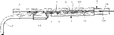
Fig. 1 is a decomposition shaft side figure, has represented a kind of safety slide with rollers for vehicle seats according to one embodiment of the invention;
Fig. 2 is the front view of the vehicle seat slide mechanism;
Fig. 3 is the birds-eye view of the vehicle seat slide mechanism;
Fig. 4 is the part sectional view of safety slide with rollers for vehicle seats shown in Figure 2;
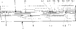
Fig. 5 is an amplification plan view according to the essential part of the safety slide with rollers for vehicle seats of the embodiment of the invention;
Fig. 6 is an amplification plan view according to the essential part of the safety slide with rollers for vehicle seats of the embodiment of the invention;
Fig. 7 is an axonometric drawing, has represented the essential part according to the safety slide with rollers for vehicle seats of the embodiment of the invention;
Fig. 8 is an explanatory diagram, has represented the working process of next lockplate of acceleration environment, and wherein, this lockplate is an assembly of safety slide with rollers for vehicle seats of the present invention.
Referring now to accompanying drawing one embodiment of the present of invention are described in detail.
As shown in figs. 1 and 4, a pair of down rail 1 is fixed on (not shown) on the floor of vehicle.Though a following rail only is shown among the figure, another same following rail also is fixed on the vehicle floor and following rail to that indicated in the drawings parallels.Following rail 1 is along the longitudinal extension of vehicle, and it bends to a specific shape (being tee section) by a single sheet material and constitutes.
The last rail 2 of pair of parallel (only illustrating one among the figure) is along the longitudinal extension of vehicle and be bearing in down slidably on the rail 1, and this is connected with the respective side of a seat with seat cushion and backrest not shown in the figures respectively last rail.Rail 2 has book plate 2a on each, the crooked and reservation shape that obtains of 2b, and this reservation shape has the plug-in type T section.Last rail 2 is by a roller unit 3 and utilize the cross sectional shape of upper and lower rail 1 and 2 to be bearing in down on the rail 1 with being free to slide.
As shown in Figs. 4-6, rail 1 has the part of curving inwardly 11 under each, and the edge of this part is made of the tooth 12 that rail under some edges vertically is provided with.In addition, rail 2 has a upright wooden partition 21 on each, and this wall is by book plate 2a, and 2b constitutes.One lockplate 5 is bearing on each and also can freely rotates on the rail 2.Lockplate 5 parallels with the upright wooden partition 21 of last rail 2, and in the middle by a pin 6 supportings, so that can freely rotate.On each side of pin 6, in the opposite end portion of lockplate 5, one end (rearward end) is made of a flange 51, and this flange 51 is along the horizontal expansion of upper and lower rail and vertical vertical with upper and lower rail.Flange 51 passes a kerf 211, and otch 211 is formed in the upright wooden partition of rail 2 and facing to the tooth 12 of rail 1 down.The other end of lockplate divides 52 to constitute by a junction, and a joystick (this joystick will be described below) is connected with this connecting bridge 52.Flange 51 has at least one pair of lock hole 53 that tooth 12 can be inserted.Each lock hole 53 all has a pair of first hole wall of relatively putting 531, and they intersect vertically with the direction of last rail with respect to rail slip down, promptly with vertically the intersecting vertically of upper and lower rail.In addition, lockplate 5 is made of a kind of deformable material, so that allow the side travel of flange 51 along upper and lower rail.This distortion can be realized by plastic deformation or elastic deformation.
Shown in Fig. 1 to 4, joystick 7 has a bow-shaped structural, and the connecting bridge 52 that corresponding lockplate 5 is passed at the two ends of joystick 7 is connected with lockplate 5.The centre portion of joystick 7 is positioned at the front side below the seat, so that can be handled by the people who is sitting on the seat.In addition, shaft-like spring 9 is arranged between lockplate 5 and the last rail 2.One end of shaft-like spring 9 is fixed on the upright wooden partition 21 of rail 2, and the other end is fixed on an end of lockplate 5 by a pin 8.Therefore, lockplate 5 is subjected to the effect of the bias pressure of spring 9, thereby makes lockplate pressurized and turn to tooth 12 to insert the direction of lock holes 53 all the time.
In above-mentioned structure, the bias voltage that is subjected to shaft-like spring 9 owing to lockplate 5 all the time forwards a first direction to, and therefore tooth 12 is inserted in the lock hole 53.Last rail 2 with respect to the slip of following rail 1 owing to the engagement between the hole wall 511 of tooth that has inserted and lock hole 53 is restricted.Therefore, seat is fixed on the desired location of vehicle floor.If joystick 7 is upwards spurred, 5 of lockplates overcome the pressure of shaft-like spring 9 and rotate on second (on the contrary) direction, thereby tooth 12 is extracted out from lock hole 53.Remove the restriction of descending the slip of rail to carry out relatively to last rail thus, thereby rail 2 can slided on the rail 1 down.This just means that seat can moving longitudinally on the desired position on the vehicle floor along vehicle.When joystick 7 unclamped, the effect that lockplate 5 is subjected to spring 9 bias pressures was rotated in a first direction, thereby made tooth 12 insert lock hole 53 once more, and the slip of rail 2 on following rail 1 gone up in restriction thus.
Shown in Fig. 7 and 8, each lock hole 53 all has a rectangular shape.First wall 531 vertically intersects vertically with upper and lower rail, and it is along the plate thickness of the horizontal width of upper and lower rail greater than tooth 12.First wall 531 shrinks by this way, that is, each lock hole 53 along upper and lower rail longitudinally width upper and lower rail outside big than inboard place longitudinally.Therefore, a primary importance A and a second place B (relative and put) at these position teeth 12 and lock hole 53 along and such direction setting, promptly this direction and last rail are with respect to rail direction of slip square crossing down, just upper and lower rail is horizontal.In addition, each all has one second wall 511 two opposite ends of the flange 51 that lockplate 5 vertically is provided with along upper and lower rail, and this wall is along vertical protrusion of upper and lower rail, and a notch 512, and this notch is positioned near second wall 511.In addition, last rail 2 all has a hook 211a respectively by vertical relative wooden partition of the otch 211 that the flange 51 of lockplate 5 passes, and this hook can and can insert the notch 512 of flange 51 in second wall, 511 engagements of the operative orientation of lockplate 5 and flange 51.Second wall 511 and notch 512 are along the groove horizontally set of upper and lower rail.When tooth 12 during at primary importance A place, hook 211a is inserted in the notch 512, when tooth mouth during at second place B place, and second wall 511 and hook 211a engagement.
In said structure, shown in solid line among Fig. 8, tooth 12 is in the first position the A place usually and hook 211 is inserted in the notch 512.Therefore, if joystick 7 is worked according to mode above-mentioned, then the lockplate 5 above-mentioned rotation that bias pressure carried out that overcomes shaft-like spring 9 is allowed to.
If the acceleration/accel that surpasses a predetermined value along vertical effect of vehicle thereon, for example when vehicle during by static flat-out acceleration, tooth 12 is meshed with first wall 531 on the opposite side with the vehicle acceleration direction of lock hole 53 tightly.As a result, flange 51 is because the distortion of the contraction structure of first wall 513 and lockplate 5 and along laterally inwardly the moving of upper and lower rail, thereby makes tooth 12 be in second place B and hook 211a meshes with second wall 511.This state as shown in phantom in Figure 8.Therefore, under these circumstances, even with mode manipulation bar 7 above-mentioned, lockplate 5 is owing to the bias voltage that the engagement of second wall 511 and hook 211a can not overcome shaft-like spring rotates.This just means that joystick 7 can not be operated.
Therefore, when the acceleration/accel that surpasses predetermined value acted on vehicle, the motion of lockplate was restricted, and joystick can not be handled.Thus, even be placed on luggage and articles on the vehicle floor in the effect whisk of acceleration/accel and bump against on the joystick, the latter will can not work yet.
Should be noted in the discussion above that along upper and lower rail vertically, only the first wall 531 on lock hole 53 front sides or only the first wall 531 on lock hole 53 rear sides need shrink towards another wall.Certainly, the first wall 531 of the forward and backward side of lock hole is as described above such, can shrink toward each other.In addition, the first wall 531 that shrinks shape needn't be as the part of lock hole 53, also can be arranged in the tooth 12 along the thickness direction of tooth (this direction and upper and lower rail vertically perpendicular).
According to the present invention, the mate of last rail or following rail can move to the second place from primary importance owing to the contraction structure of the first wall on the lockplate.Lockplate has one second wall, and this wall is used for when mate is positioned at the second place in lockplate sense of motion and last rail or rail engagement down.Therefore, when vehicle quickened, the motion of lockplate was limited by the engagement of second wall and last rail or following rail.Thus, under the situation of flat-out acceleration, joystick may be handled hardly.In addition, this point can be achieved under the situation that is no more than existing mechanism element number, thereby can reduce cost.
In addition, according to the present invention, lockplate has a notch near second wall.When mate is positioned at primary importance, lockplate will can not mesh with last rail or following rail on the sense of motion of lockplate.Can guarantee that like this lockplate can work under the situation of acceleration/accel not having.
Owing to can have many embodiment that significant difference is arranged under the spirit and scope of the present invention, so should illustrate, the present invention will only be subjected to the restriction of claims and not be subjected to the restriction of its specific embodiment.

Claims (7)

1. seat slide mechanism that is used for vehicle comprises:
Rail once, this time rail is fixed on the floor of vehicle;
Rail on one, rail is connected with a seat and is bearing on the said down rail and can automatically slides thereon on this;
One lockplate, this lockplate are arranged on said down rail and institute says between the rail, are used to limit institute's rail of saying with respect to the slip of said rail down and the releasing this restriction to last rail;
One joystick, this joystick are arranged on seat front-side underside place, are used to handle said lockplate;
One shrinks the first wall of shape, this first wall is arranged on the rail of saying, descends in rail and the lockplate, can be arranged on the rail of saying with one, down the mate on another in rail and the lockplate is meshed on the direction of last rail with respect to rail slip down, this first wall can make said mate be in a primary importance and a second place, these two positions along with last rail with respect to rail direction of slip direction setting substantially vertically down; With
One second wall, this second wall be arranged on the said lockplate and when said mate can be during in the said second place in lockplate sense of motion and institute's rail of saying or rail engagement down.
2. according to the mechanism of claim 1, it is characterized in that, said engaging plate has a notch near said second wall, when said mate during in said primary importance, said notch make said lockplate the lockplate sense of motion with saying rail or rail engagement down.
3. seat slide mechanism that is used for vehicle comprises:
A pair of down rail, this is fixed on the vehicle floor rail down and is parallel to each other and put;
The a pair of rail of going up, they are bearing in respectively on the cooresponding rail down slidably, are used to support seat; With
One blocking device, it be used to limit the rail of saying with respect to the slip of said down rail, this blocking device has: be arranged on each tooth on rail down; The lockplate that can swing, each lockplate can be meshed with cooresponding hole by the hole that is arranged on each lockplate; With some hooks, they are arranged on each on the rail, are meshed with the flange of each lockplate, keep the engagement in said tooth and said hole during along horizontal slip of last rail direction of slip with convenient lockplate.
4. mechanism as claimed in claim 3 is characterized in that, each flange of lockplate all has said hole, and these holes are limited by the pinch wall of putting relatively.
5. mechanism as claimed in claim 4 is characterized in that, lockplate is moved by horizontal the pressure with contacting of said tooth by the hole that pinch wall limited under the situation of vehicle flat-out acceleration.
6. mechanism as claimed in claim 3 is characterized in that, each flange of lockplate all has said hole, and these holes are limited by the pinch wall of putting relatively.
7. mechanism as claimed in claim 6 is characterized in that, lockplate is moved by horizontal the pressure with contacting of said tooth by the hole that pinch wall limited under the situation of vehicle flat-out acceleration.
CN96112100A 1995-06-28 1996-06-28 Vehicle seat slide mechanism Expired - Fee Related CN1078858C (en)

Applications Claiming Priority (2)

Application Number Priority Date Filing Date Title
JP162419/95 1995-06-28
JP16241995A JP3400613B2 (en) 1995-06-28 1995-06-28 Vehicle seat slide device

Publications (2)

Publication Number Publication Date
CN1167700A true CN1167700A (en) 1997-12-17
CN1078858C CN1078858C (en) 2002-02-06

Family

ID=15754247

Family Applications (1)

Application Number Title Priority Date Filing Date
CN96112100A Expired - Fee Related CN1078858C (en) 1995-06-28 1996-06-28 Vehicle seat slide mechanism

Country Status (6)

Country Link
US (1) US5829728A (en)
EP (1) EP0751029B1 (en)
JP (1) JP3400613B2 (en)
KR (1) KR100226565B1 (en)
CN (1) CN1078858C (en)
DE (1) DE69615759T2 (en)

Cited By (14)

* Cited by examiner, † Cited by third party
Publication number Priority date Publication date Assignee Title
CN100343087C (en) * 2001-03-05 2007-10-17 Ims传动装置有限公司 Longitudinal seat adjustment device, especially in motor vehicle
CN100421986C (en) * 2003-04-21 2008-10-01 岐阜车体工业株式会社 Locking gear in sliding means of seat rail of vehicle
CN100460241C (en) * 2004-12-20 2009-02-11 爱信精机株式会社 Seat slide apparatus for a vehicle
CN101175652B (en) * 2005-05-12 2010-06-09 东京座椅技术股份公司 Sliding-type automobile seat
CN1955039B (en) * 2005-10-24 2010-09-01 爱信精机株式会社 Seat sliding apparatus for vehicle
CN101157344B (en) * 2006-10-04 2010-12-01 爱信精机株式会社 Seat position adjusting apparatus for vehicle
CN102745096A (en) * 2012-07-18 2012-10-24 无锡同捷汽车设计有限公司 Novel electric seat adjusting device
CN102848936A (en) * 2012-08-29 2013-01-02 上海沿浦金属制品股份有限公司 Manual longitudinal sliding rail for car seat
CN103241139A (en) * 2012-02-03 2013-08-14 李尔公司 Seat track having selectable end stop positions
CN104411537A (en) * 2012-05-30 2015-03-11 约翰逊控股公司 Actuating unit for a vehicle seat
CN104972935A (en) * 2015-07-15 2015-10-14 芜湖仅一机械有限公司 Automobile seat
CN107757428A (en) * 2017-11-17 2018-03-06 湖北航嘉麦格纳座椅系统有限公司 A kind of sliding rail of automobile seat and its control mechanism
CN107878263A (en) * 2016-09-29 2018-04-06 博泽(科堡)汽车零部件有限公司 For the retainer used in the adjusting means of seat longitudinally adjust and such adjusting means
CN108372804A (en) * 2018-03-30 2018-08-07 延锋安道拓(烟台)座椅有限公司 A kind of seat inclines the unlocking mechanism in parallel of sliding avoidance system

Families Citing this family (27)

* Cited by examiner, † Cited by third party
Publication number Priority date Publication date Assignee Title
JP3646356B2 (en) * 1995-06-30 2005-05-11 アイシン精機株式会社 Seat slide device
EP0878342B1 (en) * 1997-05-13 2005-11-23 Delta Kogyo Co., Ltd. Automobile seat slide unit
JP3295627B2 (en) * 1997-10-21 2002-06-24 富士機工株式会社 Seat slide device
DE19757110C1 (en) * 1997-12-20 1998-11-19 Keiper Gmbh & Co Longitudinal seat adjuster for motor vehicle
EP0943484A3 (en) * 1998-03-17 2000-08-16 Ohi Seisakusho Co., Ltd. Seat slide unit
ITTO980279A1 (en) * 1998-03-31 1999-10-01 Sergio Gallo LONGITUDINAL ADJUSTMENT DEVICE FOR VEHICLE SEATS.
US6086154A (en) * 1998-03-31 2000-07-11 Dura Automotive Systems, Inc. Infinitely adjustable seat track assembly
JP2000043621A (en) * 1998-07-29 2000-02-15 Ikeda Bussan Co Ltd Vehicle seat device
JP4106137B2 (en) * 1998-11-13 2008-06-25 アイシン精機株式会社 Vehicle seat slide device
JP3560846B2 (en) * 1999-05-11 2004-09-02 富士機工株式会社 Seat slide device
JP2001171398A (en) * 1999-12-17 2001-06-26 Aisin Seiki Co Ltd Seat rail device
DE10051669C2 (en) * 2000-10-18 2003-12-24 Daimler Chrysler Ag Device for guiding a seat of a vehicle
JP4098057B2 (en) * 2002-10-11 2008-06-11 アイシン精機株式会社 Vehicle seat slide device
DE102004049404B4 (en) * 2004-10-08 2014-06-18 Johnson Controls Gmbh Device for limiting the adjustability of a component, in particular a vehicle seat, on a longitudinally extending adjustment area and vehicle seat
JP4291795B2 (en) * 2005-03-31 2009-07-08 富士機工株式会社 Vehicle seat slide device
FR2884462B1 (en) * 2005-04-18 2007-06-29 Faurecia Sieges Automobile AUTOMOTIVE VEHICLE SEAT SLIDE AND METHOD OF MANUFACTURING THE SAME
DE102005019765A1 (en) * 2005-04-28 2006-11-02 Faurecia Autositze Gmbh & Co. Kg Longitudinally adjustable motor vehicle seat, has side arms inserted into seat rail and including plates, and clamp with bar, which is formed in wave shaped W-form with two seat part abandon outer bends and central seat part facing bend
US7798462B2 (en) * 2005-05-12 2010-09-21 Ts Tech Co., Ltd. Sliding-type automobile seat
JP4355963B2 (en) * 2007-01-30 2009-11-04 株式会社今仙電機製作所 Slide rail device
JP5309802B2 (en) * 2008-09-02 2013-10-09 アイシン精機株式会社 Vehicle seat slide device
JP2010064526A (en) * 2008-09-08 2010-03-25 Denso Corp Device for limiting seat sliding operation
JP5156573B2 (en) * 2008-10-17 2013-03-06 株式会社今仙電機製作所 Slide rail device for vehicle seat
JP5816000B2 (en) * 2010-12-14 2015-11-17 デルタ工業株式会社 Seat slide device
JP6236655B2 (en) * 2014-04-25 2017-11-29 トヨタ紡織株式会社 Vehicle seat
CN105179898A (en) * 2015-07-15 2015-12-23 芜湖仅一机械有限公司 Fixing rod
IT201800005731A1 (en) 2018-05-25 2019-11-25 Slider for a vehicle seat
IT201900000313A1 (en) * 2019-01-09 2020-07-09 Martur Italy Srl Slider for a vehicle seat with an improved rail configuration

Family Cites Families (11)

* Cited by examiner, † Cited by third party
Publication number Priority date Publication date Assignee Title
US3310274A (en) * 1965-08-09 1967-03-21 Gen Motors Corp Manual seat adjuster locking device
DE6928888U (en) * 1969-07-18 1969-11-20 Daimler Benz Ag SEAT ADJUSTMENT DEVICE, IN PARTICULAR FOR VEHICLE SEATS
DE2914229C2 (en) * 1979-04-09 1983-12-22 Ford-Werke AG, 5000 Köln Motor vehicle seat mounted so as to be longitudinally displaceable
JPS5631839A (en) * 1979-08-22 1981-03-31 Aisin Seiki Co Ltd One-step feeding system seat sliding adjuster
US4556186A (en) * 1983-08-15 1985-12-03 General Motors Corporation Seat adjuster
JPH0231967A (en) * 1988-07-19 1990-02-01 Suzuki Motor Co Ltd Device for sliding seat
JPH059227Y2 (en) * 1988-07-28 1993-03-08
US4961559A (en) * 1989-12-18 1990-10-09 Chrysler Corporation Latching bar arrangement for seat adjuster
JPH0639232B2 (en) * 1990-02-09 1994-05-25 株式会社大井製作所 Seat slide device
JP2976356B2 (en) * 1990-07-05 1999-11-10 ヤマハ発動機株式会社 High pressure fuel injector for engine
US5242144A (en) * 1991-09-23 1993-09-07 Ford Motor Company Latch system seat support assembly

Cited By (17)

* Cited by examiner, † Cited by third party
Publication number Priority date Publication date Assignee Title
CN100343087C (en) * 2001-03-05 2007-10-17 Ims传动装置有限公司 Longitudinal seat adjustment device, especially in motor vehicle
CN100421986C (en) * 2003-04-21 2008-10-01 岐阜车体工业株式会社 Locking gear in sliding means of seat rail of vehicle
CN100460241C (en) * 2004-12-20 2009-02-11 爱信精机株式会社 Seat slide apparatus for a vehicle
CN101175652B (en) * 2005-05-12 2010-06-09 东京座椅技术股份公司 Sliding-type automobile seat
CN1955039B (en) * 2005-10-24 2010-09-01 爱信精机株式会社 Seat sliding apparatus for vehicle
CN101157344B (en) * 2006-10-04 2010-12-01 爱信精机株式会社 Seat position adjusting apparatus for vehicle
CN103241139A (en) * 2012-02-03 2013-08-14 李尔公司 Seat track having selectable end stop positions
CN104411537A (en) * 2012-05-30 2015-03-11 约翰逊控股公司 Actuating unit for a vehicle seat
CN104411537B (en) * 2012-05-30 2017-10-27 约翰逊控股公司 Actuating unit for seat
US10131250B2 (en) 2012-05-30 2018-11-20 Adient Luxembourg Holding S.a.r.l. Actuating unit for a vehicle seat
CN102745096A (en) * 2012-07-18 2012-10-24 无锡同捷汽车设计有限公司 Novel electric seat adjusting device
CN102848936A (en) * 2012-08-29 2013-01-02 上海沿浦金属制品股份有限公司 Manual longitudinal sliding rail for car seat
CN104972935A (en) * 2015-07-15 2015-10-14 芜湖仅一机械有限公司 Automobile seat
CN107878263A (en) * 2016-09-29 2018-04-06 博泽(科堡)汽车零部件有限公司 For the retainer used in the adjusting means of seat longitudinally adjust and such adjusting means
CN107878263B (en) * 2016-09-29 2020-12-18 博泽(科堡)汽车零部件有限公司 Adjusting device for longitudinal adjustment of a vehicle seat and holder for use therein
CN107757428A (en) * 2017-11-17 2018-03-06 湖北航嘉麦格纳座椅系统有限公司 A kind of sliding rail of automobile seat and its control mechanism
CN108372804A (en) * 2018-03-30 2018-08-07 延锋安道拓(烟台)座椅有限公司 A kind of seat inclines the unlocking mechanism in parallel of sliding avoidance system

Also Published As

Publication number Publication date
KR100226565B1 (en) 1999-10-15
KR970000804A (en) 1997-01-21
US5829728A (en) 1998-11-03
EP0751029A2 (en) 1997-01-02
CN1078858C (en) 2002-02-06
DE69615759T2 (en) 2002-08-01
EP0751029B1 (en) 2001-10-10
DE69615759D1 (en) 2001-11-15
JPH0911781A (en) 1997-01-14
EP0751029A3 (en) 1998-09-02
JP3400613B2 (en) 2003-04-28

Similar Documents

Publication Publication Date Title
CN1078858C (en) Vehicle seat slide mechanism
JP3788637B2 (en) Lockable sliding device for automobile seat
DE102009012955B4 (en) Active headrest system with a locking connection structure for a vehicle
AU694963B2 (en) Seat recliner
CN1576110A (en) Headrest apparatus for a vehicle seat
CN1133386A (en) Scaffold plate
EP0958961A3 (en) Tray for the dashboard of an automotive vehicle
JPH0636999Y2 (en) Vehicle seat slide lock device
GB2277440A (en) Intermediate armrest for a row of seats
JP2011079370A (en) Lock unit mounting structure of seat slide lock device for vehicle
EP1241047A3 (en) Backrest for vehicle seats
JP6776211B2 (en) Panel structure
JPH0537864Y2 (en)
JP3104737B2 (en) Lock mechanism for seat slide device
JP3050514B2 (en) Lock mechanism for seat slide device
CN111196187B (en) Slide rail unlocking structure matched with easy-entering function of seat
CN2409116Y (en) Motorcycle back regulator
JP3847213B2 (en) Automotive seat
JPH023444Y2 (en)
JPH046342Y2 (en)
JPH0212101Y2 (en)
JP4434765B2 (en) Fork backlash prevention device
JP2544136Y2 (en) Automotive seat slide device
KR200411305Y1 (en) Tilting device of headrest
JPH0139233Y2 (en)

Legal Events

Date Code Title Description
C10 Entry into substantive examination
SE01 Entry into force of request for substantive examination
C06 Publication
PB01 Publication
ASS Succession or assignment of patent right

Owner name: AISIN FINE MACHINE INC.; TOYOTA JIDOSHA K. K.

Free format text: FORMER OWNER: AISIN SEIKI K.K.; TOYOTA JIDOSHA K. K.

Effective date: 20010805

C41 Transfer of patent application or patent right or utility model
TA01 Transfer of patent application right

Effective date of registration: 20010805

Applicant after: AISIN SEIKI Kabushiki Kaisha

Applicant after: Toyota Motor Corp.

Applicant before: Aisin Seiki Kabushiki Kaisha

Applicant before: Toyota Motor Corp.

C14 Grant of patent or utility model
GR01 Patent grant
CF01 Termination of patent right due to non-payment of annual fee

Granted publication date: 20020206

Termination date: 20150628

EXPY Termination of patent right or utility model