CN1167562C - Arrangement for operating a transportation system with a magnetic levitation vehicle - Google Patents
Arrangement for operating a transportation system with a magnetic levitation vehicle Download PDFInfo
- Publication number
- CN1167562C CN1167562C CNB998030791A CN99803079A CN1167562C CN 1167562 C CN1167562 C CN 1167562C CN B998030791 A CNB998030791 A CN B998030791A CN 99803079 A CN99803079 A CN 99803079A CN 1167562 C CN1167562 C CN 1167562C
- Authority
- CN
- China
- Prior art keywords
- suspension
- described device
- electric motors
- linear electric
- vehicle
- Prior art date
- Legal status (The legal status is an assumption and is not a legal conclusion. Google has not performed a legal analysis and makes no representation as to the accuracy of the status listed.)
- Expired - Fee Related
Links
Images


Classifications
-
- B—PERFORMING OPERATIONS; TRANSPORTING
- B60—VEHICLES IN GENERAL
- B60L—PROPULSION OF ELECTRICALLY-PROPELLED VEHICLES; SUPPLYING ELECTRIC POWER FOR AUXILIARY EQUIPMENT OF ELECTRICALLY-PROPELLED VEHICLES; ELECTRODYNAMIC BRAKE SYSTEMS FOR VEHICLES IN GENERAL; MAGNETIC SUSPENSION OR LEVITATION FOR VEHICLES; MONITORING OPERATING VARIABLES OF ELECTRICALLY-PROPELLED VEHICLES; ELECTRIC SAFETY DEVICES FOR ELECTRICALLY-PROPELLED VEHICLES
- B60L13/00—Electric propulsion for monorail vehicles, suspension vehicles or rack railways; Magnetic suspension or levitation for vehicles
- B60L13/10—Combination of electric propulsion and magnetic suspension or levitation
-
- B—PERFORMING OPERATIONS; TRANSPORTING
- B60—VEHICLES IN GENERAL
- B60L—PROPULSION OF ELECTRICALLY-PROPELLED VEHICLES; SUPPLYING ELECTRIC POWER FOR AUXILIARY EQUIPMENT OF ELECTRICALLY-PROPELLED VEHICLES; ELECTRODYNAMIC BRAKE SYSTEMS FOR VEHICLES IN GENERAL; MAGNETIC SUSPENSION OR LEVITATION FOR VEHICLES; MONITORING OPERATING VARIABLES OF ELECTRICALLY-PROPELLED VEHICLES; ELECTRIC SAFETY DEVICES FOR ELECTRICALLY-PROPELLED VEHICLES
- B60L2200/00—Type of vehicles
- B60L2200/26—Rail vehicles
Abstract
The invention relates to an arrangement for operating a transportation system with a magnetic levitation vehicle, in which the inventive arrangement consists of an integrated transmission system including a power transmission system for inductive transmission of electric power, a linear motor for transmission of motive power and a magnetic levitation system for transmission of a carrying force and/or a lateral guiding force.
Description
Technical field
The present invention relates to a kind of device that is used to move transport systems with maglev vehicle.
Background technology
Utilize magnetic levitation technology can realize moving linearly and revolving member are carried out no touch, and thereby do not have a support of abrasion.Magnetic levitation technology replaces the contact of wheel-rail under mainly being used at a high speed aspect personnel's transportation; And aspect conveying technology its Special Significance be not have abrasion, low noise and low wearing and tearing.Thereby such delivery system is applicable to in the very high environment of hygienic requirements, as food industry, pharmacy industry and medical industry; Simultaneously, also be applicable to high-purity space or the place of explosion hazard is arranged.With regard to the ratio of the deadweight (light mass) of the load that transported and vehicle, the numerical value aspect conveying technology also is higher than personnel's transportation aspect.
Important point of view is with the vehicle suspension energy needed of getting up.Aspect personnel's transportation, this energy is because high-revolving cause can reach the level that is higher than driving power.In conveying technology, only be the speed of several metre per second (m/s)s, obviously too low.Thereby, must provide by vehicle self in order to reach the suspension energy needed.
Provided a kind of magnetic suspension-transport systems among the EP-A1 0 580 107, the vehicle that wherein suspends is driven forwards by linear electric motors on a track.The shortcoming of system is that the volume of device is big, mechanical system is complicated.
Summary of the invention
The objective of the invention is, the device that provides a kind of operation to have the transport systems of maglev vehicle, it should compact conformation, occupy-place is few, and thereby cost low.
In order to realize this purpose, the present invention proposes a kind of running gear that has the transport systems of a rail-guided maglev vehicle, has integrated transmission system, this transmission system has and is used for the energy delivery system of inductive transfer electric power, have linear electric motors and transmit driving power, and have magnetic suspension system and transmit and support and/or the side guidance force, wherein, the actv. of suspension system, the part system that is regulated is positioned on the suspension vehicle or the side, wherein, be provided with and be used for device that the mechanical air gap of suspension system is regulated, wherein, the actv. of linear electric motors, the part system that is regulated is positioned on the suspension vehicle or the side, this energy delivery system to suspension system and linear electric motors be placed on the suspension vehicle or other part system provides electric power, be provided with the mechanical air gap that is used for to suspension system, also be used for device that the mechanical air gap of linear electric motors and/or energy delivery system is regulated simultaneously.
Utilize the present invention, the complicated mechanical system can be replaced with contactless system, such system can transmit energy and/or transmission of drive force and bearing force and side guidance force, particularly is used in the maglev vehicle.It has realized the integrated of removable system that no touch drives.
Of the present invention, be used to move the device that has the maglev vehicle transport systems, have an integrated transmission system, transmission system has energy delivery system, realizes the inductive transfer of electric power, has linear electric motors, transmits the driving energy; And have magnetic suspension system, transmit bearing force and/or side guidance force.This device has following advantage: each element in the integrated transmission system, the dynamics condition that is in operation is similar, and mechanical air gap condition is similar in magnet or mechanical tolerance.Structural form simply is its advantage, and integrated transmission system particularly of the present invention can be the module structure.Additional advantage is, the assembling of local system is simple, and possible electric connection and interconnection technique are simplified, and safeguards simple in the time may needing part replacement.
In a preferred embodiment, transmission system is placed in mobile system, particularly the suspend exterior angle place of vehicle.Its advantage is the balanced configuration of transmission system, thereby can use a mobile system neatly, particularly advances and the condition of travelling that falls back can compare.Like this, simplified with regard to the change that makes the suspension vehicle heading.
Particularly advantageous is to be provided with a bogie truck to hold transmission system.Preferably be provided with at this and be, integrated transmission system is positioned in respectively on two lateral surfaces of the bogie truck that is connected with the compartment, wherein bogie truck preferably is connected with the compartment by a hinge, and this hinge can wind the rotational vertical with respect to service direction respectively.Particularly advantageous setting is that a bogie truck is respectively installed in the front and back on the compartment service direction.Transmission system being placed in two ends of the bogie truck that is connected with the compartment of a suspension vehicle, is favourable.A kind of favourable being set to is provided with a multi-directional ball joint between bogie truck and compartment.Like this, can realize turning radius especially little on the vertical surface, when transport systems of the present invention is applied to uphill way and descending highway section, have advantage.
In a kind of favourable further structure of apparatus of the present invention, the moveable portion system of magnetic suspension system, the particularly vehicle that suspends are connected by the multi-directional ball joint with bogie truck, have two independently, adjustable single magnet.Can reach suitable dynam ride characteristic like this, particularly in crooked highway section.
In the favourable improvement structure of another of apparatus of the present invention, transmission system has the converyer head that is fixed together with the suspension vehicle, and they are configured to the suspension vehicle outside is U-shape, like this U-shape leg vertically about overlapping and directed outside.If U-shape-profile is extend in the fixed in position profile partly of transmission system, then be particularly advantageous.Special benefits is like this can be at transport systems use passive type in service track switch.
Another kind of favorable structure of the present invention is, the actv. of magnetic suspension system and linear electric motors, the local system of being regulated are placed on the mobile suspension vehicle or the side, wherein preferably utilize by means of the electric energy of energy transmission device transmission and the possible information processing of being undertaken by a control unit.Its advantage is, can make any place of each mobile system on running route, all have an independent operation of travelling at any time.Special advantage is that on the identical running section and/or on the identical running section section, a plurality of mobile systems can move independently.
According to another advantageous forms of implementation of the present invention, magnetic suspension system has an adjustable mechanical air gap.The normal force action direction preferably is set, particularly along the adjusting of y-change in coordinate axis direction.The advantage of this measure is to have reduced wearing and tearing widely, and possibility is provided, and the anti-of suspension vehicle that the mechanical support element only is configured to move falls and/or auxiliary device.
Particularly advantageously be, be provided with the device that the mechanical air gap of magnetic suspension system is regulated, can regulate the mechanical air gap of linear electric motors and/or energy delivery system again simultaneously.This favourable combination makes contactless transmission system have minimized air gap.Consequently, with the comparable substantially power data of known schemes under, the weight of each transmission system of integrated transmission system is compared little with size.Corresponding, when size was suitable with quality, transferable power and/or propulsive effort then advantageously were improved.
In a kind of particularly advantageous improvement structure of apparatus of the present invention, linear electric motors are placed on the suspension vehicle like this, make the center of gravity of linear electric motors and the center of gravity of whole transmission system, when particularly considering quality of loads, be arranged in a plane (x-z-face) substantially, this plane is parallel with the moving direction of suspension vehicle.Like this, can be by of the effect of a minimized throw of lever in conjunction with propulsive effort, the disturbance torque when controlling acceleration of suspension vehicle and deceleration.
A kind of good be configured to of magnetic suspension system on mobile system and in the integrated transmission system, the air-gap surface of magnetic suspension system (y-coordinate axle) are positioned at the top of center of gravity of the whole mobile system of transmission system, consider the representative type quality of loads here.Its favourable part is, can avoid the characteristic of upright pendulum of the unstable balance of transport systems like this.
Advantageously, magnetic suspension system, linear electric motors and energy transmission device overlapping arrangement up and down in vertical direction respectively.So basically, reach a kind of optimized setting, have minimized disturbance torque, this is owing to be activated the power effect under the condition of the pendulum characteristic of having been avoided undesirable unstable balance, and/or the cause of device self structure minimized height.If additionally make the converyer head not have compact arrangement the in mechanical spacing ground, then have advantage especially.Like this, can avoid the system height of this device to be subjected to the high numerical value of essential design condition restriction in other cases.
According to the present invention, in the favourable improvement structure of another kind, energy transmission device, magnetic suspension system and linear electric motors are settled down respectively in vertical direction overlappingly, and, on the one hand the fixed part of energy transmission device and magnetic suspension system, the converyer head and the linear electric motors of suspension system are closely settled on the other hand.The advantage here is again to access favourable little system height.
Magnetic suspension system has a magnet that has the magnetic conductance yoke, and wherein, magnet and magnetic conductance yoke all have U-shape cross-sectional plane, and the leg of U-shape profile relative to each other.The advantage of this setting is to have actv. lateral guide gravitation, and it obtains by contour shape.Therefore mobile system is stablized.
Another favorable structure is, integrated transmission system has a mechanical guidance system, it be set for transport systems travel on direction control in the passive type track switch.Preferably a wheel by mechanical guidance system is to carrying out the guiding of travelling of a side direction.Wherein take turns affacting in the groove, the latter is made of the U-shape magnetic conductance yoke of magnetic suspension system.Wheel is on the bogie truck that preferably is in mobile suspension vehicle, and can be placed in couples converyer head (z coordinate axle) rigging position before or after, perhaps be respectively wheel centering single take turns be placed in converyer head rigging position before or after.
Have among the embodiment of advantage at another kind, the magnet of suspension system is settled in couples relatively, wherein, the converyer head movably, be fixed in the part of the fixed in position of the part overlap joint energy transmission device on the suspension vehicle.
Advantageously, designed device, their the feasible air gap of magnetic suspension system are regulated become possibility, make this air gap have transformable numerical value.Thereby the normal force of linear electric motors is conditioned as suspension support.Sided configuration by magnetic suspension system makes it advantageously be achieved, and this is owing to can upward regulate power at positive and negative both direction (y-coordinate axle).Like this, can make the energy requirement of system reach minimum, loss and reach minimum.
The advantageous forms of implementation of magnetic suspension system is, is provided with device, and they can make the travel direction of magnetic conductance perpendicular to the suspension vehicle.Can reach the purpose that reduces eddy current loss and improve useful lateral guide gravitation like this.
Description of drawings
Below by means of the embodiment among the figure the present invention is further specified.Wherein,
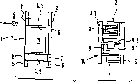
The birds-eye view of Fig. 1 device of the present invention and a detail drawing,
The detail drawing of two articulated mountings of Fig. 2,
Two kinds of arrangements of Fig. 3 magnet,
Fig. 4 supports the multi-form of magnet,
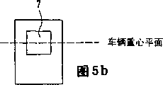
The suitable setting of Fig. 5 center of gravity,
The detail drawing of a kind of form of implementation of the integrated transmission system of Fig. 6,
Fig. 7 has the suspension vehicle of guidance device.
The specific embodiment
Figure 1 illustrates the configuration with transport systems of integrated transmission system of the present invention.Wherein, the suspension vehicle is subjected to the driving of the linear electric motors of non-contact type operation, and contactlessly obtains electric energy by an inductive transfer system.Comprise in a kind of composition of preferred integrated transmission system: the energy delivery system of a non-contact type operation is used for induction type and transmits electric energy; Linear electric motors that are used for transmission of drive force; With a magnetic suspension system, its movable part is the suspension vehicle, and its fixed part in orbit.
A transport systems 1 has four integrated transmission systems 2.In its left side of birds-eye view, can see a compartment 3, have a forecarriage 4.1 and a trailing truck 4.2.They are installed on the suspension vehicle, and this vehicle moves along a track 5.The details of suspension vehicle is not shown here.Bogie truck 4.1,4.2 couples together by a hinge 6 and compartment 3 respectively.On whole four angles of vehicle are in the side end of bogie truck 4.1,4.2, an integrated transmission system 2 has been installed respectively symmetrically.Vehicle can move along the z-coordinate axle.Hinge 6 can be a pin under the simplest situation, its allow in the horizontal direction the rotation that preferably limits by block, promptly around the rotation of y-axle.Rotation in vertical direction is unallowed, and will guarantee that bogie truck 4.1,4.2 and compartment 3 are in the same plane basically.Another suitable configurations of hinge 6 is a multi-directional ball joint, and it allows along level, vertical and azimuth direction rotation.This rotation can be restricted independently of one another by block.For in vertical direction curve applicability favourable be not only the slit of between bogie truck and compartment, leaving, but also so-called hinge rigid length is arranged.
Among Fig. 1 shown in the details drawing on right side is the details of the cross-sectional plane of an integrated transmission system 2.The left side is the part of track 5, and a bogie truck 4.1,4.2 can be seen in the right side.Lower element is represented linear electric motors 7, is settling a supporting magnet system 8 on its top, and being positioned at above it is energy transmission device head 9.Linear electric motors 7, supporting magnet system 8 and converyer head 9 have a fixed parts and a movable part here respectively, and the former is placed on the track 5, and the latter is placed on the mobile system and by bogie truck 4.1,4.2 and connects.Here, the moving-member of converyer head 9 has U-shape profile, and it protrudes in the E-shape profile of fixing counterpart.Supporting magnet system 8 has a lower member 8.1 and a magnetic conductance yoke 8.2, and these two all is U-shape, and its profile leg faces toward mutually.The moving member of linear electric motors 7 has U-shape profile, the profile on its overlap joint fixation side.The structure of integrated transmission system 2 is very compact, has passive type track switch (passive Weichen) used in permission in system advantage.
In Fig. 2, simply show two embodiment of hinge 6.In last figure, be the pin hinge, lay respectively at bogie truck 4.1,4.2 between two sides in compartment 3; Be the multi-directional ball joint in figure below, it bogie truck 4.1 or 4.2 and compartment 3 between.Because stability reasons, and because degree of freedom is bigger, the multi-directional ball joint need support the 2-configurations of magnets of magnet 8.This be since for example when vehicle quickens bogie truck 4.1,4.2 in vertical direction to tumble by a 1-configurations of magnets be unescapable.And have a device of selling hinge, for the reason of cost aspect, can only implement with the 1-configurations of magnets.At this, the rigidity of vehicle is enough for stability.Yet, also the 2-configurations of magnets can be set.
In Fig. 3, further specify with the 1-configurations of magnets and the 2-configurations of magnets of birds-eye view to support magnet.The 1-configurations of magnets that there is shown in the left side has illustrated that it is suitable for reason in conjunction with a pin hinge 6 between 4.1,4.2 and compartments 3 of bogie truck.The suspension vehicle 10 here has four support units, and they have support magnet 8, and these supporting magnet are made of the supporting magnet with a lower member 8.1 and a magnetic conductance yoke 8.2 respectively.They are placed on the side end of bogie truck 4.1,4.2.The 2-configurations of magnets that there is shown on the right side.The magnet here is the component part of integrated transmission system 2.Preferably, each magnet 8 all has the size that self an air gap sensor is determined air gap, and self a current relay.
The favorable structure of support magnet 8 has been shown among Fig. 4.Suitable support magnet 8 is electromagnet, as shown in Fig. 4 a.In this suspension theory, utilize the attractive force of an electromagnet to a ferrimagnetism yoke, yoke is made of track 5 in the drawings.The excitation of electromagnet realizes by hot-wire coil.Because this device is unsettled, air gap must be measured and made it stable by suitable coil current by the air gap sensor.Another kind of suitable support magnet 8 is made of a kind of hybrid magnet.In such device, basic excitation is born by permanent magnet, and they are connected with electromagnet.Can realize the energy-conservation magnetic suspension of vehicle like this.
In principle, vehicle can perhaps be guided by magnetic force in orbit by mechanical force or by corresponding structural constituent such as roller, sledge.The guiding here both can be an actv., also can be passive.
Belong in the guiding of active electromagnetism a kind of, except support magnet 8, also need to use other electromagnet, they remain on the vehicle on the track on the guide rail or are located between the guide rail.For this reason, preferably measure the lateral distance of guide rail, and guiding magnet is correspondingly regulated.
A kind of substitute in light weight, that cost is low is passive guiding.If at this moment an electromagnet laterally offset that is suspended under the guide rail has just produced a power, it is withdrawn into electromagnet on the midway location.This principle promptly is the magnetic resistance of knowing altogether for everybody.Form weak damped vibration thus.The suspension vehicle can advantageously be guided by reluctance force, wherein, can carry out shifted laterally.In order to realize smooth operation, to be limited the mobile possibility of side direction, preferably undertaken by gear wheel.Compare with mechanical propelling sheave, these gear wheels are not to be in running condition always, thereby they can more easily be designed.The advantageous particularly part is, in order to improve the magnetic resistance application force, is provided with a groove on the direct of travel of supporting track upper edge, utilizes it can improve the side direction restoring force, particularly roughly doubles.
An electromagnet has been shown in Fig. 4 b, and it is as the lower member 8.1 of support magnet 8.It has U-shape yoke 8.3, is twining exciting coil 11 on two leg.Exciting coil is also not shown in the drawings.Since power only with coil in current related, use a 2-quadrant regulating control enough for operation.
A hybrid magnet has been shown in Fig. 4 c.Settled a permanent-magnet material 12 in this embodiment on the pole-face of electro-magnet magnetic yoke 8.3, wherein, the leg of yoke 8.3 has among the figure again and unshowned exciting coil 11.To the selection of permanent-magnet material thickness, pay the utmost attention to and make hybrid magnet produce predetermined fixed power, and no current flows through exciting coil 11 for predetermined pole-face and the air gap between the yoke.The power that produces in order to change, or come the additional incentive hybrid magnet by exciting coil 11 galvanizations, or deenergization.Here it is favourable using the four-quadrant regulating control.
Another favorable structure of support magnet 8 has been shown in Fig. 4 d.The advantage of the hybrid magnet of application force form obtains comprehensive application here when the advantage of an electromagnet with less magnetic action air gap form and a no current, becomes so-called compound type hybrid magnet.The pole surface of an electro-magnet magnetic yoke 8.3 is only partly covered by permanent-magnet material 12.In the drawings, permanent-magnet material 12 is prepared on the exterior lateral area of pole-face, is parallel to the groove of yoke 8.3.Because permanent-magnet material 12 contacts with the yoke 8.3 of conduction on both sides, forms magnet short-cut path there.In order to reduce this short circuit, effective method is to add to leave a groove on pole-face, and it is parallel to permanent-magnet material 12.According to the design of permanent magnet 12,2-quadrant regulating control come for the electromagnet feed should be enough.
The another kind of favorable structure of supporting magnet 8 illustrates with the form of a double loop configuration in Fig. 4 e.Supporting magnet 8 is made of an electromagnet and a permanent magnet respectively, they on mechanical location by front and back or settle abreast.
In all configurations, advantageously use a magnetic conduction heel piece 8.2, it is U-shape.For this reason, the circuit element on the affiliated orbit 5 is provided with groove, and it also has the advantage that can improve the side directed forces simultaneously.At this, this circuit element must carry and support the same magnetic flux of lower member 8.1 of magnet 8.Advantage is that the lamellar iron of magnetic conductance yoke 8.2 usefulness is made, thereby can reduce eddy current loss.
In order to make the configuration of total system as far as possible stably constitute, advantageously, design system promptly, is positioned on the center of gravity of whole mobile system the air-gap surface of magnetic suspension system like this.This is shown in Fig. 5 a.Advantage is that the effect of a typical quality of loads in the suspension vehicle obtains considering simultaneously.In Fig. 5 b, provided the reasonable setting of linear electric motors 7 centers of gravity.When the center of gravity of the center of gravity of linear electric motors 7 and integrated transmission system is in the same plane substantially, then be favourable.At this moment, system is stable especially.
Figure 6 illustrates a compact especially configuration of integrated transmission system 2.Variation has taken place with respect to the embodiment among Fig. 1 here in the order of each transmission system.Here, energy transmission device head 9 below, linear electric motors 7 are in the centre, and magnetic suspension system 8 is placed in the top of integrated transmission system.
By means of the embodiment of the integrated transmission system 2 shown in Fig. 6, show one and have machinery guiding, reasonably and stable configuration.This point is provided by Fig. 7.Although used a magnetic support system, for the consideration to the safety factor of bogie truck 4.1,4.2, additional wheel 13 is set is favourable.On the one hand, wheel 13 is set at the downside of bogie truck 4.1,4.2, so that can pass through passive type track switch.These take turns 13 controls that can also take over simultaneously vehicle under the not normal situation of sudden power or other system.In addition, wheel 13 can also be set on the upside of bogie truck 4.1,4.2, because when using mictomagnet owing to linear electric motors 7 with in supporting magnet system 8, when sudden power took place, the decline of vehicle was not all may under any load condition.On the other hand, wheel 13 helps by logical trouble, and this is because the friction force of wheel 13 will be higher than an out-of-position supporting reluctance force that magnet had.Like this, wheel also can be used when negotiation of bends, so that improve the moving velocity at bend place.On bogie truck, in the zone of transmission system 2, the side of bogie truck 4.1,4.2 is separately installed with wheel 13.Such form of implementation is particularly suitable for carrying out the control of mechanical type direction in the logical trouble of passive type.Here, a wheel affacts in the groove 13, and this groove is the U-shape magnetic conductance yoke 8.2 of magnetic suspension system.The setting of wheel 13 here can be double-type, is positioned at the place ahead or the back in compartment 3, and a wheel 13 also can be set respectively, is placed in the front or the back in compartment 3.
A rational especially magnetic conductance of magnetic suspension system is to make it vertical with respect to travel direction (z-direction).The type of magnetic conductance influences the eddy current loss that produces on the travel direction when moving, and also influences the bearing force and the side guidance force of system.Because the supporting role of supporting magnet 8 need preferentially be met, normal force is greater than reluctance force, thereby magnet 8 is supported in design like this, and the normal force of magnet 8 is played a supportive role, and reluctance force is used to guiding.If magnetic conductance then with respect to for the magnetic conductance (parallel magnetic conductance) of moving direction, has advantage perpendicular to moving direction (vertical magnetic conductance).On the one hand be eddy current loss in magnetic conductance yoke 8.3 than low in the parallel magnetic conductance, this is because in comparable the moving of magnet 8, the variation of magnetic flux is very little on moving direction.On the other hand, in vertical magnetic conductance, pass through the situation of the shifted laterally of yoke 8.2 greater than parallel magnetic conductance from the yoke surfaces that track 5 stretches out.The surface that this is bigger and the variation of magnetic field energy are coupled, and the restoring force the when latter and shifted laterally is proportional.By the fluting on the track 5, side direction guide power is increased.
Claims (26)
1. the running gear that has the transport systems of a rail-guided maglev vehicle (10), has integrated transmission system (2), this transmission system (2) has and is used for the energy delivery system (9) of inductive transfer electric power, has linear electric motors (7) and transmits driving power, and have magnetic suspension system (8,8.1,8.2,8.3) transmit and support and/or the side guidance force, wherein, suspension system (8,8.1,8.2,8.3) actv., it is last or other that the part system that is regulated is positioned in suspension vehicle (10), wherein, be provided with and be used for suspension system (8,8.1,8.2,8.3) the device regulated of mechanical air gap
Wherein,
It is last or other that the actv. of linear electric motors (7), the part system that is regulated are positioned in suspension vehicle (10), this energy delivery system (9) is to suspension system (8,8.1,8.2,8.3) and linear electric motors (7) be placed in that suspension vehicle (10) is gone up or other part system provides electric power, be provided with to be used for to suspension system (8,8.1,8.2,8.3) mechanical air gap, also be used for device that the mechanical air gap of linear electric motors (7) and/or energy delivery system (9) is regulated simultaneously.
2. device as claimed in claim 1,
It is characterized by:
Transmission system (2) is placed on the external angle of suspension vehicle (10).
3. device as claimed in claim 1 or 2,
It is characterized by:
Be provided with a bogie truck (4.1,4.2) and hold transmission system (2).
4. as the described device of one of claim 1 to 2,
It is characterized by:
Between bogie truck (4.1,4.2) and compartment (3), be provided with a hinge (6).
5. as the described device of one of claim 1 to 2,
It is characterized by:
Transmission system (2) is positioned on the lateral surface of a bogie truck (4.1,4.2), and bogie truck is connected with the compartment (3) of suspension vehicle (10).
6. as the described device of one of claim 1 to 2,
It is characterized by:
Transmission system (2) is placed on two side end faces of a bogie truck (4.1,4.2), and bogie truck is connected with the compartment (3) of suspension vehicle (10).
7. as the described device of one of claim 1 to 2,
It is characterized by:
On the travel direction of suspension vehicle (10), bogie truck (4.1,4.2) is placed in the front or the back in the compartment (3) of suspension vehicle (10).
8. as the described device of one of claim 1 to 2,
It is characterized by:
A moveable portion system (8.1,8.2) of suspension system (8,8.1,8.2,8.3) have two independently, adjustable single magnet (8.1,11) so that apply bearing force.
9. as the described device of one of claim 1 to 2,
It is characterized by:
Transmission system (2) has the converyer head (9) of captiveing joint with suspension vehicle (10), and they are configured to U-shape on the outside of suspension vehicle (10), thus the mutual in vertical direction stacked and directed outside of leg that makes U-shape.
10. as the described device of one of claim 1 to 2,
It is characterized by:
Transmission system (2) captive joint with suspension vehicle (10) part converyer head (9) profile, extend into transmission system (2) maintain static the part profile in.
11. as the described device of one of claim 1 to 2,
It is characterized by:
Linear electric motors (7) are placed on the transmission system (2) like this, make the center of gravity of linear electric motors (7) and the center of gravity of whole transmission system (2) be arranged in a plane that is parallel to suspension vehicle (10) moving direction.
12. as the described device of one of claim 1 to 2,
It is characterized by:
Linear electric motors (7) are placed on the suspension vehicle (10), make and be fixed in part on the suspension vehicle (10) in the center of gravity of linear electric motors (7) and suspension vehicle (10), the transmission system (2) and the common center of gravity of quality of loads is arranged in a plane that is parallel to suspension vehicle (10) moving direction.
13. as the described device of one of claim 1 to 2,
It is characterized by:
The air-gap surface of magnetic suspension system (8,8.1,8.2,8.3) is integrated in the transmission system (2) like this, makes it be positioned at the top of the center of gravity of transmission system (2).
14. as the described device of one of claim 1 to 2,
It is characterized by:
Magnetic suspension system (8,8.1,8.2,8.3) air-gap surface be integrated into like this in the transmission system (2), that is, it is set at suspension vehicle (10) and is fixed in the part of the transmission system (2) on the suspension vehicle (10) and the top of the common center of gravity of linear electric motors (7).
15. as the described device of one of claim 1 to 2,
It is characterized by:
Magnetic suspension system (8,8.1,8.2,8.3), linear electric motors (7) and energy delivery system (9) are placed up and down respectively in vertical direction overlappingly.
16. as the described device of one of claim 1 to 2,
It is characterized by:
Magnetic suspension system (8,8.1,8.2,8.3), linear electric motors (7) and energy delivery system (9) are placed up and down respectively in vertical direction overlappingly, and wherein, suspension system (8) is placed on the linear electric motors (7).
17. as the described device of one of claim 1 to 2,
It is characterized by:
The part that is fixed in the suspension system (8) on the suspension vehicle (10) is settled by tightly adjacent no mechanical spacing ground with linear electric motors (7).
18. as the described device of one of claim 1 to 2,
It is characterized by:
Magnetic suspension system (8,8.1,8.2,8.3), linear electric motors (7) and energy transmission device (9) are placed down respectively in vertical direction overlappingly, and wherein, energy transmission device (9) is placed in the bottom to suspension system (8) in that last, linear electric motors (7) are placed in the middle.
19. as the described device of one of claim 1 to 2,
It is characterized by:
In the configuration in vertical direction, energy transmission device (9) is last, magnetic suspension system (8,8.1,8.2,8.3) placed in the middle, linear electric motors (7) are placed in the bottom, thereby one side energy transmission device (9) and magnetic suspension system (8,8.1,8.2,8.3) maintain static part, the partial sum linear electric motors (7) on the suspension vehicle (10) of being fixed in of suspension system (8) tightly are adjacent to settle on the other hand, do not have mechanical spacing.
20. as the described device of one of claim 1 to 2,
It is characterized by:
Magnetic suspension system (8,8.1,8.2,8.3) has a magnet (8.1) that has magnetic conductance yoke (8.2) and yoke (8.3), and wherein, magnetic conductance yoke (8.2) has U-shape cross-sectional plane, and its leg is towards magnet (8.1).
21. as the described device of one of claim 1 to 2,
It is characterized by:
Integrated transmission system (2) has a guidance system (13), and it is set for travel direction control in a passive type track switch and/or side guiding.
22. as the described device of one of claim 1 to 2,
It is characterized by:
Guidance system has a wheel to (13), wherein takes turns (13) are affacted in the groove, and this groove is the magnetic conductance yoke (5,8.2) of U-shape.
23. as the described device of one of claim 1 to 2,
It is characterized by:
The magnet (8.1,8.3) of suspension system (8) is to settle in pairs and relatively.
24. device as claimed in claim 23,
It is characterized by:
What be fixed in part overlap joint suspension system (8) on the suspension vehicle (10) in the suspension system (8) is placed in part on the track (5) regularly.
25. as the described device of one of claim 1 to 2,
It is characterized by:
The normal force of linear electric motors (7) is provided for as the support that suspends.
26. as the described device of one of claim 1 to 2,
It is characterized by:
By directed like this, that is, magnetic flux is led perpendicular to suspension vehicle (10) travel direction magnetic conductance yoke (8.2) with respect to the part that is fixed in the suspension system (8.1,8.3) on the suspension vehicle (10).
Applications Claiming Priority (2)
| Application Number | Priority Date | Filing Date | Title |
|---|---|---|---|
| DE19801586.0 | 1998-01-19 | ||
| DE19801586A DE19801586A1 (en) | 1998-01-19 | 1998-01-19 | Arrangement for operating transport system with rail-guided magnetically suspended vehicle |
Publications (2)
| Publication Number | Publication Date |
|---|---|
| CN1291146A CN1291146A (en) | 2001-04-11 |
| CN1167562C true CN1167562C (en) | 2004-09-22 |
Family
ID=7854871
Family Applications (1)
| Application Number | Title | Priority Date | Filing Date |
|---|---|---|---|
| CNB998030791A Expired - Fee Related CN1167562C (en) | 1998-01-19 | 1999-01-18 | Arrangement for operating a transportation system with a magnetic levitation vehicle |
Country Status (11)
| Country | Link |
|---|---|
| US (1) | US6502517B1 (en) |
| EP (1) | EP1049601B1 (en) |
| JP (1) | JP3857049B2 (en) |
| KR (1) | KR100583677B1 (en) |
| CN (1) | CN1167562C (en) |
| AT (1) | ATE217268T1 (en) |
| AU (1) | AU749681B2 (en) |
| BR (1) | BR9907030B1 (en) |
| CA (1) | CA2322888C (en) |
| DE (1) | DE19801586A1 (en) |
| WO (1) | WO1999036287A1 (en) |
Families Citing this family (31)
| Publication number | Priority date | Publication date | Assignee | Title |
|---|---|---|---|---|
| DE10240080A1 (en) * | 2002-08-30 | 2004-03-11 | Siemens Ag | Method for wireless and contactless energy and data transport and associated device |
| DE10334736A1 (en) * | 2003-07-29 | 2005-02-17 | Rexroth Indramat Gmbh | Linear motor with advancement or motion regulation for use in industrial automated processes, with bearing unit for guiding a secondary component along the desired path |
| DE10334737A1 (en) * | 2003-07-29 | 2005-02-24 | Rexroth Indramat Gmbh | Linear motor for non-contact power supply to moving consumers/modular conveying devices in automated industrial processes has a power transfer interface and field-generating coils |
| US20080223666A1 (en) * | 2005-07-09 | 2008-09-18 | Anthony Cuthbert | Traction Arrangements |
| CN100554029C (en) * | 2005-12-30 | 2009-10-28 | 中国科学院电工研究所 | Linear induction motor traction carrying device |
| CN101121384B (en) * | 2006-08-08 | 2011-05-04 | 彭雪明 | Driving system for magnetic suspension train |
| DE102006050201A1 (en) * | 2006-10-25 | 2008-04-30 | Robert Bosch Gmbh | Transverse flux machine and method for producing a transverse flux machine |
| US20090026869A1 (en) * | 2007-07-24 | 2009-01-29 | Christian Kaehler | Transverse flux reluctance machine and method for manufacturing same |
| GB2461578A (en) | 2008-07-04 | 2010-01-06 | Bombardier Transp Gmbh | Transferring electric energy to a vehicle |
| GB2461577A (en) | 2008-07-04 | 2010-01-06 | Bombardier Transp Gmbh | System and method for transferring electric energy to a vehicle |
| EP2161826B1 (en) * | 2008-09-09 | 2011-03-16 | Siemens Aktiengesellschaft | Transfer device with dynamically changeable driving ranges |
| GB2463693A (en) | 2008-09-19 | 2010-03-24 | Bombardier Transp Gmbh | A system for transferring electric energy to a vehicle |
| GB2463692A (en) | 2008-09-19 | 2010-03-24 | Bombardier Transp Gmbh | An arrangement for providing a vehicle with electric energy |
| WO2012089341A2 (en) * | 2010-12-30 | 2012-07-05 | Robert Bosch Gmbh | Magnetically mounted positioning shaft |
| KR101525559B1 (en) * | 2013-11-14 | 2015-06-03 | 한국철도기술연구원 | Linear propulsion and wireless power transfer system using 3-phase coreless ground coil |
| WO2016126494A1 (en) | 2015-02-08 | 2016-08-11 | Hyperloop Technologies, Inc. | Continuous winding for electric motors |
| WO2016126506A1 (en) | 2015-02-08 | 2016-08-11 | Hyperloop Technologies, Inc. | Low-pressure environment structures |
| WO2016126502A1 (en) | 2015-02-08 | 2016-08-11 | Hyperloop Technologies, Inc | Power supply system and method for a movable vehicle within a structure |
| WO2016126507A1 (en) | 2015-02-08 | 2016-08-11 | Hyperloop Technologies, Inc. | Gate valves and airlocks for a transportation system |
| CN107466444B (en) | 2015-02-08 | 2019-05-17 | 超级高铁技术公司 | The control of dynamic linear stator section |
| WO2016126503A1 (en) | 2015-02-08 | 2016-08-11 | Hyperloop Technologies, Inc | Transportation system |
| WO2016126492A1 (en) | 2015-02-08 | 2016-08-11 | Hyperloop Technologies, Inc. | Deployable decelerator |
| CN108702122B (en) | 2015-10-29 | 2022-06-21 | 超级高铁技术公司 | Variable frequency driving system |
| CN105346408A (en) * | 2015-11-03 | 2016-02-24 | 西南交通大学 | Series-connection type permanent magnet hybrid suspension device based on dislocation structure |
| CN105346409B (en) * | 2015-11-03 | 2017-12-19 | 西南交通大学 | A kind of cylinder type levitation device for permanent dynamic magnetic suspension train |
| US10533289B2 (en) | 2016-03-28 | 2020-01-14 | Hyperloop Technologies, Inc. | Metamaterial null flux magnet bearing system |
| CN109139723A (en) * | 2018-09-20 | 2019-01-04 | 常州明磁卓控智能科技有限公司 | A kind of magnetic suspension motor shaft coupling |
| CN109552054B (en) * | 2019-01-18 | 2023-12-05 | 张述成 | Magnetic levitation driving lifting bow device |
| CN110014848B (en) * | 2019-04-19 | 2023-11-07 | 西南交通大学 | Propelling device for magnetic levitation train |
| CN111942162B (en) * | 2020-07-07 | 2022-09-27 | 西南交通大学 | Magnetic suspension automobile |
| CN111942163B (en) * | 2020-07-07 | 2022-09-27 | 西南交通大学 | Magnetic suspension automobile with permanent magnet wheels |
Family Cites Families (8)
| Publication number | Priority date | Publication date | Assignee | Title |
|---|---|---|---|---|
| DE2220735A1 (en) * | 1972-01-20 | 1973-11-08 | Krauss Maffei Ag | ARRANGEMENT FOR NON-CONTACT MAGNETIC CARRYING OF A HOVER VEHICLE IN THE AREA OF A ROAD BREAKING |
| US3850109A (en) * | 1973-04-30 | 1974-11-26 | Massachusetts Inst Technology | Transportation system employing magnetic levitation, guidance and propulsion |
| DE3411190C2 (en) * | 1984-03-27 | 1986-11-06 | Messerschmitt-Bölkow-Blohm GmbH, 8012 Ottobrunn | Magnetic regulator for long-stator magnetic levitation vehicles |
| US4730566A (en) | 1984-09-18 | 1988-03-15 | Porter Sewing Machines, Inc. | Automatic pocket label stitcher |
| DE3578860D1 (en) * | 1984-10-23 | 1990-08-30 | Toshiba Kawasaki Kk | TYPE TRANSPORT SYSTEM WITH FLOATING CARRIER. |
| JPS631305A (en) * | 1986-06-20 | 1988-01-06 | H S S T:Kk | Structure of flexible bogie for linear motor car |
| JP2584473B2 (en) * | 1988-02-25 | 1997-02-26 | 財団法人鉄道総合技術研究所 | Cross anchor bogie type low floor vehicle for superconducting maglev railway |
| JPH01315204A (en) * | 1988-03-30 | 1989-12-20 | Toshiba Corp | Attraction type magnetic levitation apparatus |
-
1998
- 1998-01-19 DE DE19801586A patent/DE19801586A1/en not_active Withdrawn
-
1999
- 1999-01-13 US US09/600,585 patent/US6502517B1/en not_active Expired - Lifetime
- 1999-01-18 WO PCT/EP1999/000259 patent/WO1999036287A1/en active IP Right Grant
- 1999-01-18 CA CA002322888A patent/CA2322888C/en not_active Expired - Fee Related
- 1999-01-18 KR KR1020007007915A patent/KR100583677B1/en not_active IP Right Cessation
- 1999-01-18 JP JP2000540020A patent/JP3857049B2/en not_active Expired - Fee Related
- 1999-01-18 BR BRPI9907030-8B1A patent/BR9907030B1/en not_active IP Right Cessation
- 1999-01-18 EP EP99903641A patent/EP1049601B1/en not_active Expired - Lifetime
- 1999-01-18 CN CNB998030791A patent/CN1167562C/en not_active Expired - Fee Related
- 1999-01-18 AT AT99903641T patent/ATE217268T1/en active
- 1999-01-18 AU AU24219/99A patent/AU749681B2/en not_active Ceased
Also Published As
| Publication number | Publication date |
|---|---|
| US6502517B1 (en) | 2003-01-07 |
| DE19801586A1 (en) | 1999-07-22 |
| AU749681B2 (en) | 2002-07-04 |
| AU2421999A (en) | 1999-08-02 |
| JP2002509420A (en) | 2002-03-26 |
| CA2322888C (en) | 2007-09-04 |
| BR9907030A (en) | 2000-10-24 |
| KR100583677B1 (en) | 2006-05-25 |
| CN1291146A (en) | 2001-04-11 |
| KR20010040363A (en) | 2001-05-15 |
| EP1049601A1 (en) | 2000-11-08 |
| CA2322888A1 (en) | 1999-07-22 |
| WO1999036287A1 (en) | 1999-07-22 |
| BR9907030B1 (en) | 2013-06-25 |
| ATE217268T1 (en) | 2002-05-15 |
| JP3857049B2 (en) | 2006-12-13 |
| EP1049601B1 (en) | 2002-05-08 |
Similar Documents
| Publication | Publication Date | Title |
|---|---|---|
| CN1167562C (en) | Arrangement for operating a transportation system with a magnetic levitation vehicle | |
| JP4531067B2 (en) | Magnetic levitation device | |
| RU2288852C2 (en) | Device, system and method of lifting and moving of objects | |
| JP4846237B2 (en) | Magnetic suspension system | |
| US5657697A (en) | Coils for magnetic levitation apparatus | |
| CN111373097B (en) | Permanent magnetic suspension train adopting passive low-frequency electromagnetic stabilization | |
| CN1990299A (en) | Linear induction motor traction carrying device | |
| CN113352903B (en) | Wheel rail-permanent magnet suspension hybrid bearing bogie | |
| US11890946B2 (en) | Levitation control system for a transportation system | |
| CN1076677C (en) | Bidirectional electromagnet-controlled permanent magnet suspension and guiding device | |
| CN1522912A (en) | High speed rail vehicle capable of adjusting pressure on ground | |
| CA2211491A1 (en) | Self-regulating system of high speed ground transportation based on permanent magnets | |
| KR20120004865A (en) | Magnetic levitation conveyance system having spring | |
| KR20140087675A (en) | Magnetic levitation system having invertor for current angle | |
| KR20120037182A (en) | Magnetic levitation conveyance system having guide structure | |
| TW590919B (en) | Electromagnetic coil assembly for rail vehicles provided for increasing the traction | |
| CN117465227A (en) | Passenger and cargo permanent magnet suspension transportation system driven by distributed wheel type permanent magnet motor | |
| CN115547906A (en) | Single-rail cylindrical surface magnetic suspension crown block capable of inclining laterally | |
| CN117485135A (en) | Magnetic suspension bogie structure adopting rotary motor for traction | |
| Yoshida et al. | Lateral running control for air-suspended hybrid linear motor vehicle | |
| CN113212466A (en) | Mixed weight-reducing linear driving suspension type train | |
| AU2002320255B2 (en) | Apparatus, systems and methods for levitating and moving objects | |
| JPH05198427A (en) | Magnetic suspending device of magnetic levitation carrier vehicle | |
| AU2002320255A1 (en) | Apparatus, systems and methods for levitating and moving objects |
Legal Events
| Date | Code | Title | Description |
|---|---|---|---|
| C06 | Publication | ||
| PB01 | Publication | ||
| C10 | Entry into substantive examination | ||
| SE01 | Entry into force of request for substantive examination | ||
| C14 | Grant of patent or utility model | ||
| GR01 | Patent grant | ||
| CF01 | Termination of patent right due to non-payment of annual fee |
Granted publication date: 20040922 Termination date: 20150118 |
|
| EXPY | Termination of patent right or utility model |