CN116417837A - Seal ring protection end cover, connector and connector assembly - Google Patents
Seal ring protection end cover, connector and connector assembly Download PDFInfo
- Publication number
- CN116417837A CN116417837A CN202111682070.6A CN202111682070A CN116417837A CN 116417837 A CN116417837 A CN 116417837A CN 202111682070 A CN202111682070 A CN 202111682070A CN 116417837 A CN116417837 A CN 116417837A
- Authority
- CN
- China
- Prior art keywords
- connector
- cable
- housing
- flange
- protective
- Prior art date
- Legal status (The legal status is an assumption and is not a legal conclusion. Google has not performed a legal analysis and makes no representation as to the accuracy of the status listed.)
- Pending
Links
- 230000001681 protective effect Effects 0.000 claims abstract description 47
- 238000003780 insertion Methods 0.000 claims abstract description 37
- 230000037431 insertion Effects 0.000 claims abstract description 37
- 230000000903 blocking effect Effects 0.000 claims abstract description 33
- 238000007789 sealing Methods 0.000 claims abstract description 28
- 230000013011 mating Effects 0.000 claims description 7
- 238000004519 manufacturing process Methods 0.000 abstract description 4
- 238000012856 packing Methods 0.000 description 3
- 230000002093 peripheral effect Effects 0.000 description 2
- 238000009434 installation Methods 0.000 description 1
- 238000012986 modification Methods 0.000 description 1
- 230000004048 modification Effects 0.000 description 1
Images


Classifications
-
- H—ELECTRICITY
- H01—ELECTRIC ELEMENTS
- H01R—ELECTRICALLY-CONDUCTIVE CONNECTIONS; STRUCTURAL ASSOCIATIONS OF A PLURALITY OF MUTUALLY-INSULATED ELECTRICAL CONNECTING ELEMENTS; COUPLING DEVICES; CURRENT COLLECTORS
- H01R13/00—Details of coupling devices of the kinds covered by groups H01R12/70 or H01R24/00 - H01R33/00
- H01R13/46—Bases; Cases
- H01R13/52—Dustproof, splashproof, drip-proof, waterproof, or flameproof cases
- H01R13/5205—Sealing means between cable and housing, e.g. grommet
-
- H—ELECTRICITY
- H01—ELECTRIC ELEMENTS
- H01R—ELECTRICALLY-CONDUCTIVE CONNECTIONS; STRUCTURAL ASSOCIATIONS OF A PLURALITY OF MUTUALLY-INSULATED ELECTRICAL CONNECTING ELEMENTS; COUPLING DEVICES; CURRENT COLLECTORS
- H01R13/00—Details of coupling devices of the kinds covered by groups H01R12/70 or H01R24/00 - H01R33/00
- H01R13/46—Bases; Cases
- H01R13/52—Dustproof, splashproof, drip-proof, waterproof, or flameproof cases
- H01R13/5213—Covers
-
- H—ELECTRICITY
- H01—ELECTRIC ELEMENTS
- H01R—ELECTRICALLY-CONDUCTIVE CONNECTIONS; STRUCTURAL ASSOCIATIONS OF A PLURALITY OF MUTUALLY-INSULATED ELECTRICAL CONNECTING ELEMENTS; COUPLING DEVICES; CURRENT COLLECTORS
- H01R13/00—Details of coupling devices of the kinds covered by groups H01R12/70 or H01R24/00 - H01R33/00
- H01R13/46—Bases; Cases
- H01R13/52—Dustproof, splashproof, drip-proof, waterproof, or flameproof cases
- H01R13/5202—Sealing means between parts of housing or between housing part and a wall, e.g. sealing rings
-
- H—ELECTRICITY
- H01—ELECTRIC ELEMENTS
- H01R—ELECTRICALLY-CONDUCTIVE CONNECTIONS; STRUCTURAL ASSOCIATIONS OF A PLURALITY OF MUTUALLY-INSULATED ELECTRICAL CONNECTING ELEMENTS; COUPLING DEVICES; CURRENT COLLECTORS
- H01R13/00—Details of coupling devices of the kinds covered by groups H01R12/70 or H01R24/00 - H01R33/00
- H01R13/46—Bases; Cases
- H01R13/502—Bases; Cases composed of different pieces
- H01R13/506—Bases; Cases composed of different pieces assembled by snap action of the parts
-
- H—ELECTRICITY
- H01—ELECTRIC ELEMENTS
- H01R—ELECTRICALLY-CONDUCTIVE CONNECTIONS; STRUCTURAL ASSOCIATIONS OF A PLURALITY OF MUTUALLY-INSULATED ELECTRICAL CONNECTING ELEMENTS; COUPLING DEVICES; CURRENT COLLECTORS
- H01R13/00—Details of coupling devices of the kinds covered by groups H01R12/70 or H01R24/00 - H01R33/00
- H01R13/58—Means for relieving strain on wire connection, e.g. cord grip, for avoiding loosening of connections between wires and terminals within a coupling device terminating a cable
- H01R13/5804—Means for relieving strain on wire connection, e.g. cord grip, for avoiding loosening of connections between wires and terminals within a coupling device terminating a cable comprising a separate cable clamping part
- H01R13/5812—Means for relieving strain on wire connection, e.g. cord grip, for avoiding loosening of connections between wires and terminals within a coupling device terminating a cable comprising a separate cable clamping part the cable clamping being achieved by mounting the separate part on the housing of the coupling device
-
- H—ELECTRICITY
- H01—ELECTRIC ELEMENTS
- H01R—ELECTRICALLY-CONDUCTIVE CONNECTIONS; STRUCTURAL ASSOCIATIONS OF A PLURALITY OF MUTUALLY-INSULATED ELECTRICAL CONNECTING ELEMENTS; COUPLING DEVICES; CURRENT COLLECTORS
- H01R13/00—Details of coupling devices of the kinds covered by groups H01R12/70 or H01R24/00 - H01R33/00
- H01R13/64—Means for preventing incorrect coupling
-
- H—ELECTRICITY
- H01—ELECTRIC ELEMENTS
- H01R—ELECTRICALLY-CONDUCTIVE CONNECTIONS; STRUCTURAL ASSOCIATIONS OF A PLURALITY OF MUTUALLY-INSULATED ELECTRICAL CONNECTING ELEMENTS; COUPLING DEVICES; CURRENT COLLECTORS
- H01R13/00—Details of coupling devices of the kinds covered by groups H01R12/70 or H01R24/00 - H01R33/00
- H01R13/648—Protective earth or shield arrangements on coupling devices, e.g. anti-static shielding
- H01R13/658—High frequency shielding arrangements, e.g. against EMI [Electro-Magnetic Interference] or EMP [Electro-Magnetic Pulse]
- H01R13/6581—Shield structure
- H01R13/6582—Shield structure with resilient means for engaging mating connector
- H01R13/6583—Shield structure with resilient means for engaging mating connector with separate conductive resilient members between mating shield members
- H01R13/6584—Shield structure with resilient means for engaging mating connector with separate conductive resilient members between mating shield members formed by conductive elastomeric members, e.g. flat gaskets or O-rings
-
- H—ELECTRICITY
- H01—ELECTRIC ELEMENTS
- H01R—ELECTRICALLY-CONDUCTIVE CONNECTIONS; STRUCTURAL ASSOCIATIONS OF A PLURALITY OF MUTUALLY-INSULATED ELECTRICAL CONNECTING ELEMENTS; COUPLING DEVICES; CURRENT COLLECTORS
- H01R13/00—Details of coupling devices of the kinds covered by groups H01R12/70 or H01R24/00 - H01R33/00
- H01R13/648—Protective earth or shield arrangements on coupling devices, e.g. anti-static shielding
- H01R13/658—High frequency shielding arrangements, e.g. against EMI [Electro-Magnetic Interference] or EMP [Electro-Magnetic Pulse]
- H01R13/6591—Specific features or arrangements of connection of shield to conductive members
- H01R13/6592—Specific features or arrangements of connection of shield to conductive members the conductive member being a shielded cable
-
- H—ELECTRICITY
- H01—ELECTRIC ELEMENTS
- H01R—ELECTRICALLY-CONDUCTIVE CONNECTIONS; STRUCTURAL ASSOCIATIONS OF A PLURALITY OF MUTUALLY-INSULATED ELECTRICAL CONNECTING ELEMENTS; COUPLING DEVICES; CURRENT COLLECTORS
- H01R13/00—Details of coupling devices of the kinds covered by groups H01R12/70 or H01R24/00 - H01R33/00
- H01R13/46—Bases; Cases
- H01R13/52—Dustproof, splashproof, drip-proof, waterproof, or flameproof cases
- H01R13/5205—Sealing means between cable and housing, e.g. grommet
- H01R13/5208—Sealing means between cable and housing, e.g. grommet having at least two cable receiving openings
-
- H—ELECTRICITY
- H01—ELECTRIC ELEMENTS
- H01R—ELECTRICALLY-CONDUCTIVE CONNECTIONS; STRUCTURAL ASSOCIATIONS OF A PLURALITY OF MUTUALLY-INSULATED ELECTRICAL CONNECTING ELEMENTS; COUPLING DEVICES; CURRENT COLLECTORS
- H01R13/00—Details of coupling devices of the kinds covered by groups H01R12/70 or H01R24/00 - H01R33/00
- H01R13/46—Bases; Cases
- H01R13/52—Dustproof, splashproof, drip-proof, waterproof, or flameproof cases
- H01R13/521—Sealing between contact members and housing, e.g. sealing insert
-
- H—ELECTRICITY
- H01—ELECTRIC ELEMENTS
- H01R—ELECTRICALLY-CONDUCTIVE CONNECTIONS; STRUCTURAL ASSOCIATIONS OF A PLURALITY OF MUTUALLY-INSULATED ELECTRICAL CONNECTING ELEMENTS; COUPLING DEVICES; CURRENT COLLECTORS
- H01R24/00—Two-part coupling devices, or either of their cooperating parts, characterised by their overall structure
- H01R24/20—Coupling parts carrying sockets, clips or analogous contacts and secured only to wire or cable
Abstract
The invention discloses a sealing ring protection end cover, a connector and a connector assembly. The sealing washer protection end cover includes: a body having a first end for insertion into a receptacle of a connector housing and a second end for positioning outside of the housing; a first flange formed protruding on an outer circumferential surface of the first end of the body for engagement with a blocking portion in the housing to prevent the protective end cap from being pulled out of the insertion hole; and a second flange formed protruding on an outer circumferential surface of the second end of the body, adapted to abut against an outer end surface of the housing to restrict the protective end cap at a predetermined insertion position. In the invention, the seal ring protecting end cover is jointed with the shell by the flanges at the two ends, thereby simplifying the structure of the seal ring protecting end cover and the shell, reducing the volume of the connector and reducing the manufacturing cost of the connector.
Description
Technical Field
The invention relates to a sealing ring protection end cover for a connector cable, a connector comprising the sealing ring protection end cover and a connector assembly comprising the connector.
Background
In the related art, a connector for a lidar generally includes a housing, a signal terminal provided in the housing for transmitting a signal (e.g., an ethernet signal), and a cable inserted into a receptacle of the housing and electrically connected to the signal terminal. In order to achieve a waterproof sealing function, a sealing ring is generally required to be sleeved on the cable so as to realize sealing between the cable and the shell.
In order to prevent the grommet from being pulled out of the receptacle of the housing when the cable is pulled, an end cap needs to be installed at the inlet of the receptacle of the housing to block the grommet from being pulled out of the receptacle of the housing. In the prior art, the end cap is typically threadably attached to one end of the housing. However, the cost of manufacturing threaded end caps and housings is high and can also result in increased connector volume.
Disclosure of Invention
The present invention is directed to solving at least one of the above-mentioned problems and disadvantages of the prior art.
According to one aspect of the present invention, there is provided a gasket protection cap for a connector cable, comprising: a body having a first end for insertion into a receptacle of a connector housing and a second end for positioning outside of the housing; a first flange formed protruding on an outer circumferential surface of the first end of the body for engagement with a blocking portion in the housing to prevent the protective end cap from being pulled out of the insertion hole; and a second flange formed protruding on an outer circumferential surface of the second end of the body, adapted to abut against an outer end surface of the housing to restrict the protective end cap at a predetermined insertion position.
According to an exemplary embodiment of the present invention, a cable through hole extending in an axial direction thereof is formed on the body of the protective end cap to allow a cable to enter into the insertion hole of the housing via the cable through hole; an end face of the first end of the protective end cap is adapted to bear against an end of a seal ring that is fitted over the cable to prevent the seal ring from being pulled out of the receptacle of the housing.
According to another exemplary embodiment of the invention, the first flange has a first engagement surface adapted to abut against the blocking portion, and the second flange has a second engagement surface adapted to abut against the outer end surface of the housing; the first engagement surface and the second engagement surface have a predetermined distance therebetween.
According to another exemplary embodiment of the present invention, a guide slope adapted to guide the insertion of the first end of the protective end cap into the insertion hole is formed on the first flange.
According to another exemplary embodiment of the present invention, a plurality of first flanges are formed on the first end of the body, the plurality of first flanges being spaced apart along the circumference of the body; a plurality of second flanges are formed on the second end of the body, the plurality of second flanges being spaced apart along the circumference of the body.
According to another exemplary embodiment of the present invention, the first flange has an outer diameter slightly larger than an inner diameter of the receptacle to be interference fit with the receptacle; and an inner diameter of the receptacle at the blocking portion is smaller than an inner diameter of other portions of the receptacle.
According to another exemplary embodiment of the present invention, the inner diameter of the cable through hole on the protective end cover is larger than the outer diameter of the cable passing therethrough, so as to facilitate the passage of the cable therethrough.
According to another exemplary embodiment of the present invention, the first flange and the second flange are staggered in a circumferential direction of the body, and the first flange and the second flange do not overlap in an axial direction of the body.
According to another aspect of the present invention, there is provided a connector comprising: a housing formed with a jack for accommodating a cable, the jack extending to an outer end surface of the housing to form an opening; a sealing ring inserted into the insertion hole; and the sealing ring protecting end cover is inserted and connected to the opening of the jack. When the sealing ring moves towards the outer end face of the shell, the first end of the protective end cover can be propped against one end of the sealing ring, so that the sealing ring is prevented from being pulled out of the jack.
According to an exemplary embodiment of the present invention, a blocking portion is formed in the insertion hole of the housing, the blocking portion being for engaging with the first flange of the protection end cap to prevent the protection end cap from being pulled out of the insertion hole.
According to another exemplary embodiment of the invention, the blocking portion has a radial blocking surface, the first flange has a first engagement surface adapted to abut against the radial blocking surface, and the second flange has a second engagement surface adapted to abut against the outer end surface of the housing; the distance between the first engagement surface and the second engagement surface is equal to or slightly greater than the distance between the radial blocking surface of the blocking portion and the outer end surface of the housing.
According to another exemplary embodiment of the present invention, the connector further comprises: and one end of the cable passes through the cable through hole on the protection end cover and is inserted into the jack. The sealing ring is sleeved on the cable and is extruded between the inner wall of the jack and the cable so as to realize sealing between the cable and the inner wall of the jack.
According to another exemplary embodiment of the present invention, a terminal is connected to one end of the cable, and the cable and the terminal are used for transmitting ethernet signals.
According to another exemplary embodiment of the present invention, the connector further comprises: an inner housing at least partially received in the outer housing; and a terminal inserted in the inner case and electrically connected to one end of the cable.
According to another exemplary embodiment of the present invention, the connector further comprises: an electromagnetic shield circumferentially at least partially surrounding the terminals of the connector for protecting the terminals from electromagnetic interference.
According to another exemplary embodiment of the invention, one end of the electromagnetic shield is crimped onto the shielding layer of the cable, and the other end is adapted to mate with a mating distribution magnetic shield of a mating connector.
According to another exemplary embodiment of the invention, the blocking portion of the housing has a radial blocking surface adapted to abut against the first engagement surface of the first flange; one end of the housing has an outer end face adapted to abut against the second engagement face of the second flange.
According to another exemplary embodiment of the invention, the receptacle has an opening at one end of the housing, and the stop is a ring of radial flanges formed at the opening of the receptacle that protrude radially inward.
According to another aspect of the present invention, there is provided a connector assembly comprising: the connector; and a mating connector adapted to mate with the connector.
In the foregoing respective exemplary embodiments according to the present invention, the protective end cover is engaged with the housing by the flanges at both ends thereof, so that the structure of the protective end cover and the housing can be simplified, and the volume of the connector and the manufacturing cost of the connector can be reduced.
Other objects and advantages of the present invention will become apparent from the following description of the invention with reference to the accompanying drawings, which provide a thorough understanding of the present invention.
Drawings
Fig. 1 shows a schematic perspective view of a connector according to an exemplary embodiment of the invention;
FIG. 2 shows a schematic perspective view of a connector according to an exemplary embodiment of the invention with a housing removed to reveal a seal ring and protective end cap therein;
fig. 3 shows a longitudinal cross-section of a connector according to an exemplary embodiment of the invention;
FIG. 4 shows an enlarged partial schematic view of the connector shown in FIG. 3;
FIG. 5 shows a longitudinal cross-sectional view of a connector with a protective end cap removed to reveal a receptacle of a housing, according to an exemplary embodiment of the invention;
fig. 6 shows a schematic perspective view of a protective end cap of a connector according to an exemplary embodiment of the invention;
fig. 7 shows a longitudinal cross-sectional view of the protective end cap shown in fig. 6.
Detailed Description
The technical scheme of the invention is further specifically described below through examples and with reference to the accompanying drawings. In the specification, the same or similar reference numerals denote the same or similar components. The following description of embodiments of the present invention with reference to the accompanying drawings is intended to illustrate the general inventive concept and should not be taken as limiting the invention.
Furthermore, in the following detailed description, for purposes of explanation, numerous specific details are set forth in order to provide a thorough understanding of the embodiments of the present disclosure. It may be evident, however, that one or more embodiments may be practiced without these specific details. In other instances, well-known structures and devices are shown in the drawings in order to simplify the drawings.
According to one general technical concept of the present invention, there is provided a gasket protection cover for a connector cable, including: a body having a first end for insertion into a receptacle of a connector housing and a second end for positioning outside of the housing; a first flange formed protruding on an outer circumferential surface of the first end of the body for engagement with a blocking portion in the housing to prevent the protective end cap from being pulled out of the insertion hole; and a second flange formed protruding on an outer circumferential surface of the second end of the body, adapted to abut against an outer end surface of the housing to restrict the protective end cap at a predetermined insertion position.
According to another general technical concept of the present invention, there is provided a connector including: a housing formed with a jack for accommodating a cable, the jack extending to an outer end surface of the housing to form an opening; a sealing ring inserted into the insertion hole; and the sealing ring protecting end cover is inserted and connected to the opening of the jack; when the sealing ring moves towards the outer end face of the shell, the first end of the protective end cover can be propped against one end of the sealing ring, so that the sealing ring is prevented from being pulled out of the jack.
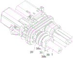
Fig. 1 shows a schematic perspective view of a connector according to an exemplary embodiment of the invention. Fig. 2 shows a schematic perspective view of a connector according to an exemplary embodiment of the present invention, wherein the housing 10 is removed to show the sealing ring 20 and the protective end cap 30 inside thereof. Fig. 5 shows a longitudinal cross-sectional view of a connector according to an exemplary embodiment of the present invention with protective end cap 30 removed to reveal receptacle 110 of housing 10.
As shown in fig. 1-2 and 5, in the illustrated embodiment, a connector adapted for connection with, for example, a lidar is disclosed that is capable of transmitting both power and signals. The connector includes: a housing 10, a seal ring 20 and a protective end cap 30. The housing 10 is formed with a receptacle 110 for receiving the cable 1. The seal ring 20 is inserted into the insertion hole 110 of the housing 10. The insertion hole 110 extends to the outer end surface 10b of the housing 10 to form an opening. The protective end cap 30 is inserted and connected over the opening of the receptacle 110. When the packing 20 moves toward the outer end surface 10b of the housing 10 (i.e., when the cable 1 is pulled outward), the first end of the protective end cap 30 may abut against one end of the packing 20 to prevent the packing 20 from being pulled out of the insertion hole 110.
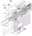
Fig. 3 shows a longitudinal cross-section of a connector according to an exemplary embodiment of the invention; FIG. 4 shows an enlarged partial schematic view of the connector shown in FIG. 3; fig. 6 shows a schematic perspective view of a protective end cap 30 of a connector according to an exemplary embodiment of the invention; fig. 7 shows a longitudinal cross-sectional view of the protective end cap 30 shown in fig. 6.
As shown in fig. 1-7, in the illustrated embodiment, the protective end cap 30 includes: a body 31, a first flange 30a and a second flange 30b. In the illustrated embodiment, the body 31 is cylindrical. The body 31 has first and second ends opposite in the axial direction thereof. The first end of the body 31 is adapted to be inserted into a receptacle 110 of the housing 10 of the connector. The second end of the body 31 is adapted to be positioned outside the housing 10.
As shown in fig. 1 to 7, in the illustrated embodiment, a blocking portion 10a is formed in the insertion hole 110 of the housing 10. The blocking portion 10a is adapted to engage the first flange 30a of the protective end cap 30 to prevent the protective end cap 30 from being pulled out of the receptacle 110.
As shown in fig. 1-7, in the illustrated embodiment, the receptacle 110 has an opening at one end 11 of the housing 10, and the stop 10a may be a ring of radial flanges formed at the opening of the receptacle 110 that project radially inward.
As shown in fig. 1 to 7, in the illustrated embodiment, a first flange 30a is formed protruding on an outer peripheral surface of the first end of the body 31. The first flange 30a is adapted to engage a stop 10a in the housing 10 to prevent the protective end cap 30 from being pulled out of the receptacle 110.
As shown in fig. 1 to 7, in the illustrated embodiment, a second flange 30b is formed protruding on the outer peripheral surface of the second end of the body 31. The second flange 30b is adapted to abut against the outer end face 10b of the housing 10 to restrain the protective end cap 30 at a predetermined insertion position. In this way, the protective end cap 30 can be prevented from being fully inserted into the insertion hole 110 of the housing 10.
As shown in fig. 1 to 7, in the illustrated embodiment, the connector further comprises a cable 1. A cable through-hole 301 extending in the axial direction thereof is formed on the body 31 of the protective end cap 30 to allow the cable 1 to enter the insertion hole 110 of the housing 10 via the cable through-hole 301. In the illustrated embodiment, the cable 1 may be an ethernet signal cable for transmitting ethernet signals. The end face of the first end of the protective end cap 30 is adapted to abut against an end of the sealing ring 20 fitted over the cable 1 to prevent the sealing ring 20 from being pulled out of the insertion hole 110 of the housing 10.
As shown in fig. 1 to 7, in the illustrated embodiment, the blocking portion 10a in the housing 10 has a radial blocking surface. The first flange 30a of the protective end cap 30 has a first engagement surface 320a adapted to abut against a radial blocking surface of the housing 10. The second flange 30b of the protective end cap 30 has a second engagement surface 320b adapted to abut against the outer end surface 10b of the housing 10. Is positioned for ease of installation and manufacture, in one exemplary embodiment of the present invention, the first engagement surface 320a and the second engagement surface 320b have a predetermined distance therebetween, e.g., the distance between the first engagement surface 320a and the second engagement surface 320b may be equal to or slightly greater than the distance between the radial blocking surface of the blocking portion 10a and the outer end surface 10b of the housing 10.
As shown in fig. 1 to 7, in the illustrated embodiment, a tapered guide slope 310 adapted to guide the insertion of the first end of the protection cap 30 into the insertion hole 110 is formed on the first flange 30 a. In this way, the first end of the protective end cap 30 can be conveniently inserted into the receptacle 110 of the housing 10.
As shown in fig. 1 to 7, in the illustrated embodiment, a plurality of first flanges 30a are formed on a first end of the body 31, the plurality of first flanges 30a being arranged at intervals along the circumferential direction of the body 31. A plurality of second flanges 30b are formed on the second end of the body 31, the plurality of second flanges 30b being arranged at intervals along the circumferential direction of the body 31. In the illustrated embodiment, two first flanges 30a are formed on a first end of the body 31 and two second flanges 30b are formed on a second end of the body 31. However, the number and shape of the first flange 30a and the second flange 30b are not limited to the illustrated embodiment, and may be appropriately set according to the actual circumstances.
As shown in fig. 1-7, in the illustrated embodiment, the outer diameter of the first flange 30a is slightly larger than the inner diameter of the receptacle 110 to provide an interference fit with the receptacle 110. The inner diameter of the insertion hole 110 at the blocking portion 10a is smaller than the inner diameter of the other portion of the insertion hole 110. That is, the inner diameter of the blocking portion 10a is smaller than the inner diameter of the other portion of the insertion hole 110.
As shown in fig. 1 to 7, in the illustrated embodiment, the inner diameter of the cable through hole 301 of the protective end cover 30 is larger than the outer diameter of the cable 1 passing therethrough, so that the cable 1 can be easily passed therethrough.
As shown in fig. 1 to 7, in the illustrated embodiment, the first flange 30a and the second flange 30b are staggered in the circumferential direction of the body 31, and the first flange 30a and the second flange 30b do not overlap in the axial direction of the body 31.
As shown in fig. 1-7, in the illustrated embodiment, the connector further includes an inner housing 40 and a pair of terminals 50. The housing 10 is fitted over the inner housing 40, and a pair of terminals 50 are provided in the inner housing. One end of the cable 1 is electrically connected to a pair of terminals 50. In the illustrated embodiment, the cable 1 and the pair of terminals 50 are used for transmitting, for example, ethernet signals. In the illustrated embodiment, the connector also includes an electromagnetic shield 60. The electromagnetic shield 60 circumferentially at least partially surrounds the pair of terminals 50 for protecting the pair of terminals 50 from electromagnetic interference, for example, for protecting the pair of terminals 50 from interference from a power terminal (not shown) of the connector.
As shown in fig. 1 to 7, in the illustrated embodiment, one end of the electromagnetic shield 60 is crimped onto the shield layer of the cable 1, and the other end of the electromagnetic shield 60 at least partially surrounds the pair of terminals 50. The other end of the electromagnetic shield 60 is adapted to mate with a mating distribution magnetic shield (not shown) of a mating connector.
As shown in fig. 1 to 7, in the illustrated embodiment, the connector includes a power terminal (not shown) for transmitting power and a signal terminal (not shown) for transmitting other signals (e.g., CAN signals) in addition to the terminal 50 for transmitting an ethernet signal.
Although not illustrated, in one exemplary embodiment of the present invention, a connector assembly is also disclosed, the connector assembly comprising: the connector and a mating connector (not shown) adapted to mate with the connector.
It will be appreciated by those skilled in the art that the above-described embodiments are exemplary and that modifications may be made to the embodiments described in various embodiments without structural or conceptual aspects and that these variations may be resorted to without departing from the scope of the invention.
Although the present invention has been described with reference to the accompanying drawings, the examples disclosed in the drawings are intended to illustrate preferred embodiments of the invention and are not to be construed as limiting the invention.
Although a few embodiments of the present general inventive concept have been shown and described, it would be appreciated by those skilled in the art that changes may be made in these embodiments without departing from the principles and spirit of the general inventive concept, the scope of which is defined in the claims and their equivalents.
It should be noted that the word "comprising" does not exclude other elements or steps, and that the word "a" or "an" does not exclude a plurality. In addition, any element numbers of the claims should not be construed as limiting the scope of the invention.
Claims (19)
1. A gasket protection end cap for a connector cable, comprising:
a body having a first end for insertion into a receptacle of a connector housing and a second end for positioning outside of the housing;
a first flange formed protruding on an outer circumferential surface of the first end of the body for engagement with a blocking portion in the housing to prevent the protective end cap from being pulled out of the insertion hole; and
and a second flange formed protruding on an outer circumferential surface of the second end of the body, adapted to abut against an outer end surface of the housing to restrict the protective end cap to a predetermined insertion position.
2. The gasket protection cap for a connector cable of claim 1, wherein:
a cable through hole extending along the axial direction of the body of the protective end cover is formed on the body of the protective end cover so as to allow a cable to enter the jack of the shell through the cable through hole;
an end face of the first end of the protective end cap is adapted to bear against an end of a seal ring that is fitted over the cable to prevent the seal ring from being pulled out of the receptacle of the housing.
3. The gasket protection cap for a connector cable of claim 1, wherein:
the first flange having a first engagement surface adapted to bear against the stop and the second flange having a second engagement surface adapted to bear against the outer end surface of the housing;
the first engagement surface and the second engagement surface have a predetermined distance therebetween.
4. The gasket protection cap for a connector cable of claim 1, wherein:
a guide ramp is formed on the first flange adapted to guide insertion of the first end of the protective end cap into the receptacle.
5. The gasket protection cap for a connector cable of claim 1, wherein:
a plurality of first flanges are formed on the first end of the body, and the plurality of first flanges are arranged at intervals along the circumferential direction of the body;
a plurality of second flanges are formed on the second end of the body, the plurality of second flanges being spaced apart along the circumference of the body.
6. The gasket protection cap for a connector cable of claim 1, wherein:
the outer diameter of the first flange is slightly larger than the inner diameter of the jack so as to be in interference fit with the jack; and is also provided with
The inner diameter of the insertion hole at the blocking portion is smaller than the inner diameter of other portions of the insertion hole.
7. The gasket protection cap for a connector cable of claim 2, wherein:
the inner diameter of the cable through hole on the protective end cover is larger than the outer diameter of the cable passing through the cable through hole so as to facilitate the cable passing through the cable through hole.
8. The gasket protection cap for a connector cable of any one of claims 1-7, wherein:
the first flange and the second flange are staggered in the circumferential direction of the body, and the first flange and the second flange do not overlap in the axial direction of the body.
9. A connector, comprising:
a housing formed with a jack for accommodating a cable, the jack extending to an outer end surface of the housing to form an opening;
a sealing ring inserted into the insertion hole; and
the gasket protection cap for a connector cable of any one of claim 1 to 8, being inserted and connected to an opening of said insertion hole,
when the sealing ring moves towards the outer end face of the shell, the first end of the protective end cover can be propped against one end of the sealing ring, so that the sealing ring is prevented from being pulled out of the jack.
10. The connector of claim 9, wherein:
a blocking portion is formed in the receptacle of the housing for engaging the first flange of the protective end cap to prevent the protective end cap from being pulled out of the receptacle.
11. The connector of claim 10, wherein:
the blocking portion having a radial blocking surface, the first flange having a first engagement surface adapted to bear against the radial blocking surface, the second flange having a second engagement surface adapted to bear against the outer end surface of the housing;
the distance between the first engagement surface and the second engagement surface is equal to or slightly greater than the distance between the radial blocking surface of the blocking portion and the outer end surface of the housing.
12. The connector of claim 9, further comprising:
one end of the cable passes through the cable through hole on the protection end cover and is inserted into the jack;
the sealing ring is sleeved on the cable and is extruded between the inner wall of the jack and the cable so as to realize sealing between the cable and the inner wall of the jack.
13. The connector of claim 12, wherein:
one end of the cable is connected with a terminal, and the cable and the terminal are used for transmitting Ethernet signals.
14. The connector of claim 12, further comprising:
an inner housing at least partially received in the outer housing; and
and the terminal is inserted in the inner shell and is electrically connected with one end of the cable.
15. The connector of claims 9-14, further comprising:
an electromagnetic shield circumferentially at least partially surrounding the terminals of the connector for protecting the terminals from electromagnetic interference.
16. The connector of claim 15, wherein:
one end of the electromagnetic shield is crimped on the shielding layer of the cable, and the other end is suitable for being matched with a matched distribution magnetic shielding piece of a matched connector.
17. The connector of claim 10, wherein:
the blocking portion of the housing having a radial blocking surface adapted to abut against the first engagement surface of the first flange;
one end of the housing has an outer end face adapted to abut against the second engagement face of the second flange.
18. The connector of claim 10, wherein:
the receptacle has an opening at one end of the housing, and the stop is a radially inwardly projecting ring of radial flanges formed at the opening of the receptacle.
19. A connector assembly, comprising:
the connector of any one of claims 9-18; and
a mating connector adapted to mate with the connector.
Priority Applications (5)
| Application Number | Priority Date | Filing Date | Title |
|---|---|---|---|
| CN202111682070.6A CN116417837A (en) | 2021-12-31 | 2021-12-31 | Seal ring protection end cover, connector and connector assembly |
| JP2022207714A JP2023099497A (en) | 2021-12-31 | 2022-12-26 | Protective end cover, connector, and connector assembly |
| EP22216951.8A EP4207509A1 (en) | 2021-12-31 | 2022-12-28 | Protection end cover, connector and connector assembly |
| US18/147,812 US20230216236A1 (en) | 2021-12-31 | 2022-12-29 | Protection End Cover, Connector and Connector Assembly |
| KR1020220190257A KR20230104051A (en) | 2021-12-31 | 2022-12-30 | Protection end cover, connector and connector assembly |
Applications Claiming Priority (1)
| Application Number | Priority Date | Filing Date | Title |
|---|---|---|---|
| CN202111682070.6A CN116417837A (en) | 2021-12-31 | 2021-12-31 | Seal ring protection end cover, connector and connector assembly |
Publications (1)
| Publication Number | Publication Date |
|---|---|
| CN116417837A true CN116417837A (en) | 2023-07-11 |
Family
ID=84688341
Family Applications (1)
| Application Number | Title | Priority Date | Filing Date |
|---|---|---|---|
| CN202111682070.6A Pending CN116417837A (en) | 2021-12-31 | 2021-12-31 | Seal ring protection end cover, connector and connector assembly |
Country Status (5)
| Country | Link |
|---|---|
| US (1) | US20230216236A1 (en) |
| EP (1) | EP4207509A1 (en) |
| JP (1) | JP2023099497A (en) |
| KR (1) | KR20230104051A (en) |
| CN (1) | CN116417837A (en) |
Family Cites Families (3)
| Publication number | Priority date | Publication date | Assignee | Title |
|---|---|---|---|---|
| US9577367B2 (en) * | 2014-04-09 | 2017-02-21 | Delphi Technologies, Inc. | Sealed connector with an extended seal sleeve and an anti-water pooling retainer |
| CN110611199A (en) * | 2018-09-30 | 2019-12-24 | 中航光电科技股份有限公司 | Wiring connector |
| KR102633954B1 (en) * | 2018-12-12 | 2024-02-05 | 현대자동차주식회사 | Integrated multipole connector |
-
2021
- 2021-12-31 CN CN202111682070.6A patent/CN116417837A/en active Pending
-
2022
- 2022-12-26 JP JP2022207714A patent/JP2023099497A/en active Pending
- 2022-12-28 EP EP22216951.8A patent/EP4207509A1/en active Pending
- 2022-12-29 US US18/147,812 patent/US20230216236A1/en active Pending
- 2022-12-30 KR KR1020220190257A patent/KR20230104051A/en unknown
Also Published As
| Publication number | Publication date |
|---|---|
| JP2023099497A (en) | 2023-07-13 |
| US20230216236A1 (en) | 2023-07-06 |
| EP4207509A1 (en) | 2023-07-05 |
| KR20230104051A (en) | 2023-07-07 |
Similar Documents
| Publication | Publication Date | Title |
|---|---|---|
| JP5766979B2 (en) | connector | |
| JP5875136B2 (en) | connector | |
| US5645450A (en) | Shielded connector | |
| US3994553A (en) | Discharge resistant cable connector | |
| US10486625B1 (en) | Grommet and wire harness | |
| WO2013111915A1 (en) | Connector unit | |
| KR890002605A (en) | Light bulb assembly | |
| KR20140146590A (en) | Gas generator | |
| EP0270270B1 (en) | Electrical connector housing assembly | |
| US20070202739A1 (en) | Coaxial plug connector for a coaxial cable | |
| CN116417837A (en) | Seal ring protection end cover, connector and connector assembly | |
| CN216929015U (en) | Sealing washer protection end cover, connector and connector assembly | |
| EP0893853B1 (en) | Shield connector | |
| CN216672020U (en) | Connector sealing assembly, connector and connector assembly | |
| CN218448613U (en) | Connector and connector assembly | |
| JP2019002453A (en) | Packing | |
| US20240136775A1 (en) | Connector and Connector Assembly | |
| CN116417840A (en) | Connector seal assembly, connector and connector assembly | |
| CN220963839U (en) | Via hole connector | |
| US20230062211A1 (en) | Connectors and Connector Assembly | |
| US20240030694A1 (en) | Cable Inlet Pass-Through Strain Relief Guide | |
| US20230387623A1 (en) | Connection terminal, finger protective cap, connection terminal assembly, cable assembly, and charging seat | |
| CN219267961U (en) | Connector with a plurality of connectors | |
| US20230027106A1 (en) | Wire harness | |
| EP4116133A1 (en) | Connector housing assembly and connector |
Legal Events
| Date | Code | Title | Description |
|---|---|---|---|
| PB01 | Publication | ||
| PB01 | Publication | ||
| SE01 | Entry into force of request for substantive examination | ||
| SE01 | Entry into force of request for substantive examination |