CN116417840A - Connector seal assembly, connector and connector assembly - Google Patents
Connector seal assembly, connector and connector assembly Download PDFInfo
- Publication number
- CN116417840A CN116417840A CN202111659649.0A CN202111659649A CN116417840A CN 116417840 A CN116417840 A CN 116417840A CN 202111659649 A CN202111659649 A CN 202111659649A CN 116417840 A CN116417840 A CN 116417840A
- Authority
- CN
- China
- Prior art keywords
- cable
- seal
- connector
- housing
- peripheral wall
- Prior art date
- Legal status (The legal status is an assumption and is not a legal conclusion. Google has not performed a legal analysis and makes no representation as to the accuracy of the status listed.)
- Pending
Links
- 238000007789 sealing Methods 0.000 claims abstract description 50
- 230000013011 mating Effects 0.000 claims abstract description 24
- 238000009434 installation Methods 0.000 claims abstract description 3
- 230000002093 peripheral effect Effects 0.000 claims description 79
- 230000004308 accommodation Effects 0.000 claims description 17
- 230000004048 modification Effects 0.000 description 1
- 238000012986 modification Methods 0.000 description 1
Images


Classifications
-
- H—ELECTRICITY
- H01—ELECTRIC ELEMENTS
- H01R—ELECTRICALLY-CONDUCTIVE CONNECTIONS; STRUCTURAL ASSOCIATIONS OF A PLURALITY OF MUTUALLY-INSULATED ELECTRICAL CONNECTING ELEMENTS; COUPLING DEVICES; CURRENT COLLECTORS
- H01R13/00—Details of coupling devices of the kinds covered by groups H01R12/70 or H01R24/00 - H01R33/00
- H01R13/46—Bases; Cases
- H01R13/52—Dustproof, splashproof, drip-proof, waterproof, or flameproof cases
- H01R13/5205—Sealing means between cable and housing, e.g. grommet
- H01R13/5208—Sealing means between cable and housing, e.g. grommet having at least two cable receiving openings
-
- H—ELECTRICITY
- H01—ELECTRIC ELEMENTS
- H01R—ELECTRICALLY-CONDUCTIVE CONNECTIONS; STRUCTURAL ASSOCIATIONS OF A PLURALITY OF MUTUALLY-INSULATED ELECTRICAL CONNECTING ELEMENTS; COUPLING DEVICES; CURRENT COLLECTORS
- H01R13/00—Details of coupling devices of the kinds covered by groups H01R12/70 or H01R24/00 - H01R33/00
- H01R13/46—Bases; Cases
- H01R13/502—Bases; Cases composed of different pieces
-
- H—ELECTRICITY
- H01—ELECTRIC ELEMENTS
- H01R—ELECTRICALLY-CONDUCTIVE CONNECTIONS; STRUCTURAL ASSOCIATIONS OF A PLURALITY OF MUTUALLY-INSULATED ELECTRICAL CONNECTING ELEMENTS; COUPLING DEVICES; CURRENT COLLECTORS
- H01R13/00—Details of coupling devices of the kinds covered by groups H01R12/70 or H01R24/00 - H01R33/00
- H01R13/46—Bases; Cases
- H01R13/52—Dustproof, splashproof, drip-proof, waterproof, or flameproof cases
- H01R13/5202—Sealing means between parts of housing or between housing part and a wall, e.g. sealing rings
-
- H—ELECTRICITY
- H01—ELECTRIC ELEMENTS
- H01R—ELECTRICALLY-CONDUCTIVE CONNECTIONS; STRUCTURAL ASSOCIATIONS OF A PLURALITY OF MUTUALLY-INSULATED ELECTRICAL CONNECTING ELEMENTS; COUPLING DEVICES; CURRENT COLLECTORS
- H01R13/00—Details of coupling devices of the kinds covered by groups H01R12/70 or H01R24/00 - H01R33/00
- H01R13/46—Bases; Cases
- H01R13/52—Dustproof, splashproof, drip-proof, waterproof, or flameproof cases
- H01R13/5205—Sealing means between cable and housing, e.g. grommet
-
- H—ELECTRICITY
- H01—ELECTRIC ELEMENTS
- H01R—ELECTRICALLY-CONDUCTIVE CONNECTIONS; STRUCTURAL ASSOCIATIONS OF A PLURALITY OF MUTUALLY-INSULATED ELECTRICAL CONNECTING ELEMENTS; COUPLING DEVICES; CURRENT COLLECTORS
- H01R13/00—Details of coupling devices of the kinds covered by groups H01R12/70 or H01R24/00 - H01R33/00
- H01R13/46—Bases; Cases
- H01R13/52—Dustproof, splashproof, drip-proof, waterproof, or flameproof cases
- H01R13/521—Sealing between contact members and housing, e.g. sealing insert
-
- H—ELECTRICITY
- H01—ELECTRIC ELEMENTS
- H01R—ELECTRICALLY-CONDUCTIVE CONNECTIONS; STRUCTURAL ASSOCIATIONS OF A PLURALITY OF MUTUALLY-INSULATED ELECTRICAL CONNECTING ELEMENTS; COUPLING DEVICES; CURRENT COLLECTORS
- H01R13/00—Details of coupling devices of the kinds covered by groups H01R12/70 or H01R24/00 - H01R33/00
- H01R13/648—Protective earth or shield arrangements on coupling devices, e.g. anti-static shielding
- H01R13/658—High frequency shielding arrangements, e.g. against EMI [Electro-Magnetic Interference] or EMP [Electro-Magnetic Pulse]
- H01R13/6581—Shield structure
-
- H—ELECTRICITY
- H01—ELECTRIC ELEMENTS
- H01R—ELECTRICALLY-CONDUCTIVE CONNECTIONS; STRUCTURAL ASSOCIATIONS OF A PLURALITY OF MUTUALLY-INSULATED ELECTRICAL CONNECTING ELEMENTS; COUPLING DEVICES; CURRENT COLLECTORS
- H01R24/00—Two-part coupling devices, or either of their cooperating parts, characterised by their overall structure
- H01R24/20—Coupling parts carrying sockets, clips or analogous contacts and secured only to wire or cable
-
- H—ELECTRICITY
- H01—ELECTRIC ELEMENTS
- H01R—ELECTRICALLY-CONDUCTIVE CONNECTIONS; STRUCTURAL ASSOCIATIONS OF A PLURALITY OF MUTUALLY-INSULATED ELECTRICAL CONNECTING ELEMENTS; COUPLING DEVICES; CURRENT COLLECTORS
- H01R27/00—Coupling parts adapted for co-operation with two or more dissimilar counterparts
- H01R27/02—Coupling parts adapted for co-operation with two or more dissimilar counterparts for simultaneous co-operation with two or more dissimilar counterparts
Abstract
The invention discloses a connector sealing assembly, a connector and a connector assembly. The connector seal assembly includes: an outer case having a plurality of seal mounting portions provided therein; a cable seal mounted on a cable seal mounting portion of the plurality of seal mounting portions for effecting a seal between the outer housing and a cable extending into the outer housing; and a housing seal member mounted on a housing seal member mounting portion of the plurality of seal member mounting portions for effecting a seal between the outer housing and a mating housing of the mating connector. In the invention, the cable sealing member and the shell sealing member are arranged in the outer shell, so that the size of the connector can be reduced, the installation difficulty of the cable sealing member can be reduced, and the sealing reliability can be improved.
Description
Technical Field
The present invention relates to a connector seal assembly, a connector including the connector seal assembly, and a connector assembly including the connector.
Background
In the related art, a connector for a lidar generally includes an outer housing, an inner housing provided in the outer housing, and terminals provided in the inner housing for transmitting signals (e.g., ethernet signals) and power. In the prior art, in order to achieve a watertight sealing function, it is often also necessary to provide a cable seal in the inner housing, which cable seal is fitted over the cable to achieve a seal between the cable and the outer housing. In addition, in order to achieve sealing between the housings, a housing seal for achieving sealing between the outer housing and the mating housing of the mating connector is also provided in the outer housing.
However, in the related art, since the cable seal and the housing seal need to be provided in the inner housing and the outer housing, respectively, this may result in a complicated structure and an excessive volume of the connector.
Disclosure of Invention
The present invention is directed to solving at least one of the above-mentioned problems and disadvantages of the prior art.
According to one aspect of the present invention, there is provided a connector seal assembly comprising: an outer case having a plurality of seal mounting portions provided therein; a cable seal mounted on a cable seal mounting portion of the plurality of seal mounting portions for effecting a seal between the outer housing and a cable extending into the outer housing; and a housing seal member mounted on a housing seal member mounting portion of the plurality of seal member mounting portions for effecting a seal between the outer housing and a mating housing of the mating connector.
According to an exemplary embodiment of the invention, the cable seal comprises: a first cable seal for sealing a portion of the cable of the connector; and/or a second cable seal for sealing another portion of the cable of the connector. The outer case has formed therein: a first receiving cavity for receiving the first cable seal, a cavity wall of the first receiving cavity being in sealing engagement with the first cable seal; and a second receiving cavity for receiving the second cable seal, a cavity wall of the second receiving cavity being in sealing engagement with the second cable seal.
According to another exemplary embodiment of the present invention, the connector seal assembly further comprises: and the sealing ring protection end cover is fixedly arranged on the opening of the first accommodating cavity and used for keeping the first cable sealing piece in the first accommodating cavity.
According to another exemplary embodiment of the present invention, the outer housing comprises: an outer peripheral wall; an inner peripheral wall radially spaced from the outer peripheral wall; and a radial side wall connected between the outer peripheral wall and the inner peripheral wall, the inner peripheral wall isolating the first accommodation chamber and the second accommodation chamber from each other; a third accommodation chamber for accommodating the housing seal member is formed between the outer peripheral wall, the inner peripheral wall, and the radial side wall.
According to another exemplary embodiment of the present invention, the housing seal is provided on the outside of the inner peripheral wall and is in sealing engagement with the inner peripheral wall.
According to another exemplary embodiment of the present invention, the housing seal member is an annular seal ring and is fitted over an outer peripheral surface of the inner peripheral wall; an outer peripheral surface of the housing seal member is radially spaced from an inner peripheral surface of the outer peripheral wall by a predetermined gap to allow the counter housing to be inserted between the housing seal member and the outer peripheral wall.
According to another exemplary embodiment of the present invention, the cable seal is adapted to seal a plurality of different types and/or different sizes of cables simultaneously; a plurality of different cable through holes adapted to mate with a plurality of different types and/or sizes of cables, respectively, are formed in the cable seal.
According to another exemplary embodiment of the present invention, the cable seal includes a first cable seal and a second cable seal, at least two different cable through holes being formed on at least one of the first cable seal and the second cable seal.
According to another exemplary embodiment of the present invention, a catching groove is formed on an inner circumferential wall of the outer housing, the catching groove being adapted to engage with a protrusion on an inner housing of a connector to fix the inner housing to the outer housing.
According to another aspect of the present invention, there is provided a connector seal assembly comprising an outer housing; the outer shell is internally provided with a first accommodating cavity and a second accommodating cavity which are respectively used for installing a first cable sealing piece and a second cable sealing piece; the outer housing includes: an outer peripheral wall, the inner side of which is provided with a cavity for accommodating an inner shell of the connector; an inner peripheral wall radially spaced from the outer peripheral wall forming a third receiving cavity for receiving a housing seal; and radial side walls respectively connected with the outer peripheral wall and the inner peripheral wall to form an integral piece.
According to another exemplary embodiment of the present invention, a housing seal member mounting portion is provided on an outer wall of the inner peripheral wall for mounting the housing seal member.
According to another exemplary embodiment of the present invention, a cable seal mounting portion is provided on an inner wall of the inner peripheral wall for mounting the first cable seal and the second cable seal.
According to another aspect of the present invention, there is provided a connector comprising: the aforementioned connector seal assembly; and an inner housing at least partially received in the outer housing.
According to an exemplary embodiment of the present invention, the connector further comprises: and a cable extending into the outer case and the inner case and passing through the cable sealing member, the cable including a signal cable for transmitting a signal and a power cable for transmitting power.
According to another exemplary embodiment of the present invention, the cable includes: a first cable for transmitting a first signal; a second cable for transmitting a second signal different from the first signal; and a third cable for transmitting electric power.
According to another exemplary embodiment of the present invention, the connector further comprises: a first terminal disposed in the inner case and electrically connected with the first cable; a second terminal disposed in the inner case and electrically connected with the second cable; and a third terminal disposed in the inner case and electrically connected with the third cable.
According to another exemplary embodiment of the present invention, the first cable is an ethernet cable for transmitting ethernet signals, and the connector further comprises a shield disposed in the inner housing; the shield is electrically connected to a shield layer of the first cable, and the first terminal is at least partially received in the shield.
According to another exemplary embodiment of the present invention, the cable seal comprises a first cable seal and a second cable seal; forming a first cable through hole on the first cable seal adapted to mate with the first cable; a second cable through hole adapted to be mated with the second cable and a third cable through hole adapted to be mated with the third cable are formed on the second cable seal.
According to another exemplary embodiment of the present invention, the outer diameter of the first cable is larger than the outer diameters of the second cable and the third cable, and the inner diameter of the first cable through hole is larger than the inner diameters of the second cable through hole and the third cable through hole; and an outer diameter of the third cable is larger than an outer diameter of the second cable, and an inner diameter of the third cable through hole is larger than an inner diameter of the second cable through hole.
According to another exemplary embodiment of the present invention, the first cable sealing member is an annular sealing ring and is sleeved on the first cable; the second cable sealing member includes a sealing body in a block shape, and the second cable through hole and the third cable through hole are formed on the sealing body.
According to another exemplary embodiment of the present invention, the connector further comprises: and the shielding connection elastic sheet is arranged on the inner shell and is used for electrically connecting the shielding piece of the connector and the matching shielding piece of the matching connector.
According to another aspect of the present invention, there is provided a connector assembly comprising: the connector; and a mating connector adapted to mate with the connector.
In the foregoing respective exemplary embodiments according to the present invention, both the cable seal and the housing seal are provided in the outer housing, so that the size of the connector can be reduced, and the difficulty of installation of the cable seal and the improvement of seal reliability can be reduced.
Other objects and advantages of the present invention will become apparent from the following description of the invention with reference to the accompanying drawings, which provide a thorough understanding of the present invention.
Drawings
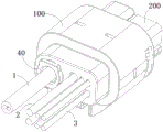
Fig. 1 shows a schematic perspective view of a connector according to an exemplary embodiment of the invention;
fig. 2 shows a longitudinal cross-section of a connector according to an exemplary embodiment of the invention;
fig. 3 shows another longitudinal cross-sectional view of a connector according to an exemplary embodiment of the invention with the inner housing removed;
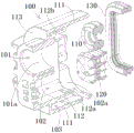
FIG. 4 shows an exploded schematic view of the outer housing, cable seal, and housing seal of a connector according to an exemplary embodiment of the invention;
FIG. 5 shows an assembled schematic view of an outer housing, cable seal, and housing seal of a connector according to an example embodiment of the invention;
FIG. 6 shows an assembled schematic view of a cable and cable seal of a connector according to an exemplary embodiment of the invention;
fig. 7 shows a schematic perspective view of the second cable seal shown in fig. 6.
Detailed Description
The technical scheme of the invention is further specifically described below through examples and with reference to the accompanying drawings. In the specification, the same or similar reference numerals denote the same or similar components. The following description of embodiments of the present invention with reference to the accompanying drawings is intended to illustrate the general inventive concept and should not be taken as limiting the invention.
Furthermore, in the following detailed description, for purposes of explanation, numerous specific details are set forth in order to provide a thorough understanding of the embodiments of the present disclosure. It may be evident, however, that one or more embodiments may be practiced without these specific details. In other instances, well-known structures and devices are shown in the drawings in order to simplify the drawings.
According to one general technical concept of the present invention, there is provided a connector sealing assembly including: an outer case having a plurality of seal mounting portions provided therein; a cable seal mounted on a cable seal mounting portion of the plurality of seal mounting portions for effecting a seal between the outer housing and a cable extending into the outer housing; and a housing seal member mounted on a housing seal member mounting portion of the plurality of seal member mounting portions for effecting a seal between the outer housing and a mating housing of the mating connector.
According to another general technical concept of the present invention, there is provided a connector sealing assembly including an outer housing; the outer shell is internally provided with a first accommodating cavity and a second accommodating cavity which are respectively used for installing a first cable sealing piece and a second cable sealing piece; the outer housing includes: an outer peripheral wall, the inner side of which is provided with a cavity for accommodating an inner shell of the connector; an inner peripheral wall radially spaced from the outer peripheral wall forming a third receiving cavity for receiving a housing seal; and radial side walls respectively connected with the outer peripheral wall and the inner peripheral wall to form an integral piece.
According to another general technical concept of the present invention, there is provided a connector including: the aforementioned connector seal assembly; and an inner housing at least partially received in the outer housing.
Fig. 1 shows a schematic perspective view of a connector according to an exemplary embodiment of the invention. Fig. 2 shows a longitudinal cross-section of a connector according to an exemplary embodiment of the invention. Fig. 3 shows another longitudinal cross-sectional view of a connector according to an exemplary embodiment of the present invention, with the inner housing 200 removed. Fig. 4 shows an exploded schematic view of the outer housing 100, cable seals 110, 120, and housing seal 130 of a connector according to an exemplary embodiment of the invention.
As shown in fig. 1 to 4, in the illustrated embodiment, a connector suitable for connection with, for example, a lidar is disclosed, the connector comprising a power supply terminal for transmitting power and a signal terminal for transmitting a signal. The connector includes: the connector seal assembly, the inner housing 200 and the cable 123. The connector seal assembly includes: an outer housing 100, cable seals 110, 120, and a housing seal 130. The inner case 200 is at least partially accommodated in the outer case 100. The cables 1, 2, 3 extend into the outer housing 100 and the inner housing 200 and pass through the cable seals 110, 120.
As shown in fig. 1 to 4, in the illustrated embodiment, the inside of the outer case 100 is provided with a plurality of seal mounting portions 101a, 102a, 112b. The cable seals 110, 120 are mounted on the cable seal mounting portions 101a, 102a of the plurality of seal mounting portions 101a, 102a, 112b for effecting sealing between the outer housing 100 and the cables 1, 2, 3 extending into the outer housing 100. The housing seal 130 is mounted on the housing seal mounting portion 112b of the plurality of seal mounting portions 101a, 102a, 112b for effecting a seal between the outer housing 100 and the mating housing of the mating connector.
Fig. 5 shows an assembled schematic view of the outer housing 100, cable seals 110, 120 and housing seal 130 of the connector according to an exemplary embodiment of the invention.
As shown in fig. 1 to 5, in the illustrated embodiment, cable seals 110, 120 are accommodated in the outer housing 100 for effecting a seal between the outer housing 100 and the cables 1, 2, 3 extending into the outer housing 100. A housing seal 130 is accommodated in the outer housing 100 for sealing between the outer housing 100 and a mating housing (not shown) of a mating connector (not shown).
As shown in fig. 1-5, in the illustrated embodiment, the cable seals 110, 120 include: a first cable seal 110 and a second cable seal 120. The first cable seal 110 is used to seal a portion of the cable 1 of the connector. The second cable seal 120 is used to seal another part of the cables 2, 3 of the connector.
As shown in fig. 1 to 5, in the illustrated embodiment, an outer case 100 is formed with: a first accommodation chamber 101, a second accommodation chamber 102, and a third accommodation chamber 103. The first receiving cavity 101 is for receiving a first cable seal 110, and a cavity wall of the first receiving cavity 101 is in sealing engagement with the first cable seal 110. The second receiving cavity 102 is for receiving a second cable seal 120, and a cavity wall of the second receiving cavity 102 is in sealing engagement with the second cable seal 120. The third accommodation chamber 103 accommodates the housing seal member 130. The first, second and third accommodation chambers 101, 102 and 103 in the outer case 100 are isolated from each other.
As shown in fig. 1-5, in the illustrated embodiment, the connector seal assembly further includes a seal ring protecting end cap 40. The gasket protection cap 40 is fixedly disposed on the opening of the first receiving chamber 101 for holding the first cable seal 110 within the first receiving chamber 101 to prevent the first cable seal 110 from being pulled out of the first receiving chamber 101.
As shown in fig. 1 to 5, in the illustrated embodiment, the outer case 100 includes: an outer peripheral wall 111, an inner peripheral wall 112, and a radial side wall 113. The inner peripheral wall 112 is radially spaced from the outer peripheral wall 111. The radial side wall 113 is connected between one end of the outer peripheral wall 111 and the inner peripheral wall 112. The first accommodation chamber 101 and the second accommodation chamber 102 are surrounded by the inner peripheral wall 112 and are isolated from each other. The third accommodation chamber 103 is defined between the outer peripheral wall 111, the inner peripheral wall 112 and the radial side wall 113. The housing seal 130 is disposed on the outside of the inner peripheral wall 112 and sealingly engages the inner peripheral wall 112.
As shown in fig. 1 to 5, in the illustrated embodiment, a card slot 112a is formed on the inner peripheral wall 112 of the outer case 100. The card slot 112a is adapted to engage with a protrusion 212a on the inner housing 200 of the connector to secure the inner housing 200 to the outer housing 100. The manner of fixing between the outer case 100 and the inner case 200 is not limited to the illustrated embodiment, and other suitable manners may be adopted.
As shown in fig. 1-5, in the illustrated embodiment, the housing seal 130 is an annular seal ring and is fitted over the outer peripheral surface of the inner peripheral wall 112. The outer peripheral surface of the housing seal member 130 is radially spaced apart from the inner peripheral surface of the outer peripheral wall 111 of the outer housing 100 by a predetermined gap to allow the mating housing of the mating connector to be inserted between the housing seal member 130 and the outer peripheral wall 111 of the outer housing 100. That is, the housing seal 130 is radially pressed between the mating housing of the mating connector and the outer peripheral wall 111 of the outer housing 100, thereby achieving a seal therebetween.
Fig. 6 shows an assembled schematic view of the cables 1, 2, 3 and cable seals 110, 120 of the connector according to an exemplary embodiment of the invention; fig. 7 shows a perspective view of the second cable seal 120 shown in fig. 6.
As shown in fig. 1-7, in the illustrated embodiment, the cable seals 110, 120 are adapted to simultaneously seal a plurality of different types and/or sizes of cables 1, 2, 3. For example, a plurality of different cable through holes 122, 123 may be formed on the cable seals 110, 120 that are adapted to mate with a plurality of different types and/or sizes of cables 1, 2, 3, respectively.
As shown in fig. 1-7, in the illustrated embodiment, the cable seals 110, 120 include a first cable seal 110 and a second cable seal 120. At least two different cable through holes 122, 123 are formed on at least one of the first and second cable seals 110, 120 for mating with at least two different types and/or different sizes of cables 2, 3.
As shown in fig. 1 to 7, in an exemplary embodiment of the present invention, there is also disclosed a connector including: the aforementioned connector seal assembly, inner housing 200 and cables 1, 2, 3. The inner case 200 is at least partially accommodated in the outer case 100. The cable 123 extends into the outer housing 100 and the inner housing 200 and through the cable seals 110, 120.
As shown in fig. 1 to 7, in the illustrated embodiment, the cables 1, 2, 3 comprise signal cables 1, 2 for transmitting signals and power cables 3 for transmitting power. That is, the connector is a hybrid connector adapted to transmit signals and power simultaneously, and for example, the connector may be a hybrid connector for connection with a lidar.
As shown in fig. 1 to 7, in the illustrated embodiment, the cables 1, 2, 3 comprise: a first cable 1, a second cable 2 and a third cable 3. The first cable 1 is used for transmitting first signals, for example for transmitting ethernet signals. The second cable 2 is used for transmitting a second signal different from the first signal, for example for transmitting a local area network signal. The third cable 3 is used for transmitting electric power.
As shown in fig. 1 to 7, in the illustrated embodiment, the connector further includes: a first terminal 10, a second terminal 20 and a third terminal 30. The first terminal 10 is disposed in the inner case 200 and electrically connected with the first cable 1. The second terminal 20 is disposed in the inner housing 200 and is electrically connected with the second cable 2. The third terminal 30 is disposed in the inner case 200 and electrically connected with the third cable 3.
As shown in fig. 1 to 7, in the illustrated embodiment, the first cable 1 is an ethernet cable for transmitting ethernet signals, and the connector further comprises a shield 11 provided in the inner housing 200. The shield 11 is electrically connected to the shield layer of the first cable 1, and the first terminal 10 is at least partially accommodated in the shield 11. In this way, electromagnetic shielding can be provided for the first terminal 10, preventing signal interference.
As shown in fig. 1 to 7, in the illustrated embodiment, the connector further includes a pair of shield connection clips (not shown). A pair of shield connection spring pieces are respectively installed on both sides of the inner housing 200 for electrically connecting the shield 11 of the connector and the mating shield (not shown) of the mating connector.
As shown in fig. 1-7, in the illustrated embodiment, the cable seals 110, 120 include a first cable seal 110 and a second cable seal 120. A first cable through hole adapted to be fitted with the first cable 1 is formed on the first cable seal 110. A second cable through hole 122 adapted to be fitted with the second cable 2 and a third cable through hole 123 adapted to be fitted with the third cable 3 are formed on the second cable seal 120.
As shown in fig. 1 to 7, in the illustrated embodiment, the outer diameter of the first cable 1 is larger than the outer diameters of the second cable 2 and the third cable 3, and the inner diameter of the first cable through hole is larger than the inner diameters of the second cable through hole 122 and the third cable through hole 123. The outer diameter of the third cable 3 is larger than the outer diameter of the second cable 2, and the inner diameter of the third cable through hole 123 is larger than the inner diameter of the second cable through hole 122.
As shown in fig. 1-7, in the illustrated embodiment, the first cable seal 110 is an annular seal ring and fits over the first cable 1. The second cable seal 120 includes a seal body 121 in a block shape, and a second cable through hole 122 and a third cable through hole 123 are formed on the seal body 121.
As shown in fig. 1-7, in one exemplary embodiment of the present invention, a connector seal assembly is also disclosed that includes an outer housing 100. The outer housing 100 is provided therein with a first accommodation chamber 101 and a second accommodation chamber 102 for mounting a first cable seal 110 and a second cable seal 120, respectively. The outer case 100 includes: an outer peripheral wall 111 having a cavity 104 provided inside thereof for accommodating an inner housing 200 of the connector; an inner peripheral wall 112, the inner peripheral wall 112 being radially spaced from the outer peripheral wall 111, forming a third accommodation chamber 103 for accommodating the housing seal 130; and radial side walls 113 connected to the outer peripheral wall 111 and the inner peripheral wall 112, respectively, to form an integral piece.
As shown in fig. 1 to 7, in the illustrated embodiment, a housing seal member mounting portion 112b for mounting the housing seal member 130 is provided on the outer wall of the inner peripheral wall 112. Cable seal mounting portions 101a, 102a for mounting the first cable seal 110 and the second cable seal 120 are provided on the inner wall of the inner peripheral wall 112.
Although not illustrated, in one exemplary embodiment of the present invention, a connector assembly is also disclosed, the connector assembly comprising: the connector and a mating connector (not shown) adapted to mate with the connector.
It will be appreciated by those skilled in the art that the above-described embodiments are exemplary and that modifications may be made to the embodiments described in various embodiments without structural or conceptual aspects and that these variations may be resorted to without departing from the scope of the invention.
Although the present invention has been described with reference to the accompanying drawings, the examples disclosed in the drawings are intended to illustrate preferred embodiments of the invention and are not to be construed as limiting the invention.
Although a few embodiments of the present general inventive concept have been shown and described, it would be appreciated by those skilled in the art that changes may be made in these embodiments without departing from the principles and spirit of the general inventive concept, the scope of which is defined in the claims and their equivalents.
It should be noted that the word "comprising" does not exclude other elements or steps, and that the word "a" or "an" does not exclude a plurality. In addition, any element numbers of the claims should not be construed as limiting the scope of the invention.
Claims (22)
1. A connector seal assembly, comprising:
an outer case having a plurality of seal mounting portions provided therein;
a cable seal mounted on a cable seal mounting portion of the plurality of seal mounting portions for effecting a seal between the outer housing and a cable extending into the outer housing; and
and a housing seal member mounted on a housing seal member mounting portion of the plurality of seal member mounting portions for effecting a seal between the outer housing and a mating housing of the mating connector.
2. The connector seal assembly of claim 1 wherein:
the cable seal includes:
a first cable seal for sealing a portion of the cable of the connector; and/or
A second cable seal for sealing another part of the cables (2, 3) of the connector, the outer housing having formed therein:
a first receiving cavity for receiving the first cable seal, a cavity wall of the first receiving cavity being in sealing engagement with the first cable seal; and
and a second receiving cavity for receiving the second cable seal, a cavity wall of the second receiving cavity being in sealing engagement with the second cable seal.
3. The connector seal assembly of claim 2 further comprising:
and the sealing ring protection end cover is fixedly arranged on the opening of the first accommodating cavity and used for keeping the first cable sealing piece in the first accommodating cavity.
4. The connector seal assembly of claim 2 wherein:
the outer housing includes:
an outer peripheral wall;
an inner peripheral wall radially spaced from the outer peripheral wall; and
a radial side wall connected between the outer peripheral wall and the inner peripheral wall,
the inner peripheral wall separates the first accommodation chamber and the second accommodation chamber from each other;
a third accommodation chamber for accommodating the housing seal member is formed between the outer peripheral wall, the inner peripheral wall, and the radial side wall.
5. The connector seal assembly of claim 4 wherein:
the housing seal is disposed on an outer side of the inner peripheral wall and is in sealing engagement with the inner peripheral wall.
6. The connector seal assembly of claim 4 wherein:
the shell sealing piece is an annular sealing ring and is sleeved on the outer peripheral surface of the inner peripheral wall;
an outer peripheral surface of the housing seal member is radially spaced from an inner peripheral surface of the outer peripheral wall by a predetermined gap to allow the counter housing to be inserted between the housing seal member and the outer peripheral wall.
7. The connector seal assembly according to any one of claims 1-6, wherein:
the cable seal is adapted to simultaneously seal a plurality of different types and/or different sizes of cables;
a plurality of different cable through holes adapted to mate with a plurality of different types and/or sizes of cables, respectively, are formed in the cable seal.
8. The connector seal assembly of claim 7 wherein:
the cable seal includes a first cable seal and a second cable seal,
at least two different cable through holes are formed in at least one of the first and second cable seals.
9. The connector seal assembly of claim 4 wherein:
a catch is formed on the inner peripheral wall of the outer housing and is adapted to engage with a projection on the inner housing of the connector to secure the inner housing to the outer housing.
10. A connector seal assembly comprising an outer housing;
the outer shell is internally provided with a first accommodating cavity and a second accommodating cavity which are respectively used for installing a first cable sealing piece and a second cable sealing piece;
the outer housing includes:
an outer peripheral wall, the inner side of which is provided with a cavity for accommodating an inner shell of the connector;
an inner peripheral wall radially spaced from the outer peripheral wall forming a third receiving cavity for receiving a housing seal; and
and the radial side wall is respectively connected with the outer peripheral wall and the inner peripheral wall to form an integral piece.
11. The connector seal assembly of claim 10 wherein:
and a shell seal mounting part is arranged on the outer wall of the inner peripheral wall and used for mounting the shell seal.
12. The connector seal assembly of claim 10 wherein:
and a cable sealing piece installation part is arranged on the inner wall of the inner peripheral wall and is used for installing the first cable sealing piece and the second cable sealing piece.
13. A connector, comprising:
the connector seal assembly of any one of claims 1-12; and
an inner housing at least partially received in the outer housing.
14. The connector of claim 13, further comprising:
a cable extending into the outer and inner housings and passing through the cable seal,
the cables include a signal cable for transmitting signals and a power cable for transmitting power.
15. The connector of claim 14, wherein: the cable includes:
a first cable for transmitting a first signal;
a second cable for transmitting a second signal different from the first signal; and
and a third cable for transmitting power.
16. The connector of claim 15, further comprising:
a first terminal disposed in the inner case and electrically connected with the first cable;
a second terminal disposed in the inner case and electrically connected with the second cable; and
and a third terminal disposed in the inner case and electrically connected to the third cable.
17. The connector of claim 16, wherein:
the first cable is an ethernet cable for transmitting ethernet signals, and the connector further comprises a shield disposed in the inner housing;
the shield is electrically connected to a shield layer of the first cable, and the first terminal is at least partially received in the shield.
18. The connector of claim 17, wherein:
the cable seal includes a first cable seal and a second cable seal;
forming a first cable through hole on the first cable seal adapted to mate with the first cable;
a second cable through hole adapted to be mated with the second cable and a third cable through hole adapted to be mated with the third cable are formed on the second cable seal.
19. The connector of claim 18, wherein:
the outer diameter of the first cable is larger than the outer diameters of the second cable and the third cable, and the inner diameter of the first cable through hole is larger than the inner diameters of the second cable through hole and the third cable through hole; and is also provided with
The outer diameter of the third cable is larger than that of the second cable, and the inner diameter of the third cable through hole is larger than that of the second cable through hole.
20. The connector of claim 18, wherein:
the first cable sealing element is an annular sealing ring and is sleeved on the first cable;
the second cable sealing member includes a sealing body in a block shape, and the second cable through hole and the third cable through hole are formed on the sealing body.
21. The connector of claim 17, further comprising:
and the shielding connection elastic sheet is arranged on the inner shell and is used for electrically connecting the shielding piece of the connector and the matching shielding piece of the matching connector.
22. A connector assembly, comprising:
the connector of any one of claims 13-21; and
a mating connector adapted to mate with the connector.
Priority Applications (5)
| Application Number | Priority Date | Filing Date | Title |
|---|---|---|---|
| CN202111659649.0A CN116417840A (en) | 2021-12-31 | 2021-12-31 | Connector seal assembly, connector and connector assembly |
| JP2022207715A JP2023099498A (en) | 2021-12-31 | 2022-12-26 | Connector sealing assembly, connector, and connector assembly |
| EP22216949.2A EP4207507A1 (en) | 2021-12-31 | 2022-12-28 | Connector sealing assembly, connector, and connector assembly |
| US18/147,794 US20230216238A1 (en) | 2021-12-31 | 2022-12-29 | Connector Sealing Assembly, Connector, and Connector Assembly |
| KR1020220190264A KR20230104052A (en) | 2021-12-31 | 2022-12-30 | Connector sealing assembly, connector, and connector assembly |
Applications Claiming Priority (1)
| Application Number | Priority Date | Filing Date | Title |
|---|---|---|---|
| CN202111659649.0A CN116417840A (en) | 2021-12-31 | 2021-12-31 | Connector seal assembly, connector and connector assembly |
Publications (1)
| Publication Number | Publication Date |
|---|---|
| CN116417840A true CN116417840A (en) | 2023-07-11 |
Family
ID=84688406
Family Applications (1)
| Application Number | Title | Priority Date | Filing Date |
|---|---|---|---|
| CN202111659649.0A Pending CN116417840A (en) | 2021-12-31 | 2021-12-31 | Connector seal assembly, connector and connector assembly |
Country Status (5)
| Country | Link |
|---|---|
| US (1) | US20230216238A1 (en) |
| EP (1) | EP4207507A1 (en) |
| JP (1) | JP2023099498A (en) |
| KR (1) | KR20230104052A (en) |
| CN (1) | CN116417840A (en) |
Family Cites Families (7)
| Publication number | Priority date | Publication date | Assignee | Title |
|---|---|---|---|---|
| FR2786033A1 (en) * | 1998-11-17 | 2000-05-19 | Whitaker Corp | Electric/fibre optic connector wire sealing technique having outer sleeving wire covering and forming connector interface seal |
| WO2007131534A1 (en) * | 2006-05-12 | 2007-11-22 | Fci | Sealed electrical connector and process for manufacturing the same |
| US7371115B1 (en) * | 2006-12-15 | 2008-05-13 | Delphi Technologies, Inc. | Mat seal device |
| JP6033430B2 (en) * | 2012-07-23 | 2016-11-30 | モレックス エルエルシー | Electrical harness connector system with differential pair connection link |
| US9577367B2 (en) * | 2014-04-09 | 2017-02-21 | Delphi Technologies, Inc. | Sealed connector with an extended seal sleeve and an anti-water pooling retainer |
| CN109038118B (en) * | 2018-06-25 | 2022-06-24 | 富士康(昆山)电脑接插件有限公司 | Cable assembly with improved cable retention |
| KR102633954B1 (en) * | 2018-12-12 | 2024-02-05 | 현대자동차주식회사 | Integrated multipole connector |
-
2021
- 2021-12-31 CN CN202111659649.0A patent/CN116417840A/en active Pending
-
2022
- 2022-12-26 JP JP2022207715A patent/JP2023099498A/en active Pending
- 2022-12-28 EP EP22216949.2A patent/EP4207507A1/en active Pending
- 2022-12-29 US US18/147,794 patent/US20230216238A1/en active Pending
- 2022-12-30 KR KR1020220190264A patent/KR20230104052A/en unknown
Also Published As
| Publication number | Publication date |
|---|---|
| JP2023099498A (en) | 2023-07-13 |
| KR20230104052A (en) | 2023-07-07 |
| EP4207507A1 (en) | 2023-07-05 |
| US20230216238A1 (en) | 2023-07-06 |
Similar Documents
| Publication | Publication Date | Title |
|---|---|---|
| KR101938932B1 (en) | Electrical connector | |
| JP5875136B2 (en) | connector | |
| JP5766979B2 (en) | connector | |
| US9570831B2 (en) | Retaining structure for terminal fitting | |
| US20170222358A1 (en) | Connector | |
| WO2012157503A1 (en) | Waterproof connector | |
| WO2012026972A1 (en) | Plug assembly | |
| US10971854B2 (en) | Shielded connector | |
| CN216672020U (en) | Connector sealing assembly, connector and connector assembly | |
| US20230216232A1 (en) | Hybrid connector housing, hybrid connector and connector assembly | |
| CN116417840A (en) | Connector seal assembly, connector and connector assembly | |
| CN216671983U (en) | Connector housing assembly, connector and connector assembly | |
| JP7174028B2 (en) | connector | |
| EP4207508A1 (en) | Connector housing assembly, connector and connector assembly | |
| CN218448613U (en) | Connector and connector assembly | |
| EP4116133A1 (en) | Connector housing assembly and connector | |
| EP4207509A1 (en) | Protection end cover, connector and connector assembly | |
| CN113471761B (en) | Plug connector and socket connector | |
| US10784628B2 (en) | Electrical plug connector | |
| CN219267961U (en) | Connector with a plurality of connectors | |
| CN217903543U (en) | Connector housing and connector | |
| JP2023099328A (en) | Shield connection element and high voltage connector | |
| KR20230117054A (en) | High voltage connector housing, high voltage connector and high voltage connector assembly | |
| CN116073171A (en) | Monopolar connector, multi-socket connector and connector system comprising same | |
| CN117832891A (en) | Cable assembly, connector and connector assembly |
Legal Events
| Date | Code | Title | Description |
|---|---|---|---|
| PB01 | Publication | ||
| PB01 | Publication | ||
| SE01 | Entry into force of request for substantive examination | ||
| SE01 | Entry into force of request for substantive examination |