CN116395382A - Collaborative mobile transportation method and system based on multiple robots - Google Patents
Collaborative mobile transportation method and system based on multiple robots Download PDFInfo
- Publication number
- CN116395382A CN116395382A CN202310334233.4A CN202310334233A CN116395382A CN 116395382 A CN116395382 A CN 116395382A CN 202310334233 A CN202310334233 A CN 202310334233A CN 116395382 A CN116395382 A CN 116395382A
- Authority
- CN
- China
- Prior art keywords
- robot
- transported
- lifting
- mold
- robots
- Prior art date
- Legal status (The legal status is an assumption and is not a legal conclusion. Google has not performed a legal analysis and makes no representation as to the accuracy of the status listed.)
- Pending
Links
- 238000000034 method Methods 0.000 title claims abstract description 32
- 230000007246 mechanism Effects 0.000 claims abstract description 80
- 239000012636 effector Substances 0.000 claims description 59
- 230000008569 process Effects 0.000 claims description 11
- 238000004364 calculation method Methods 0.000 claims description 6
- 238000013459 approach Methods 0.000 claims description 3
- 239000000945 filler Substances 0.000 claims description 3
- 239000000463 material Substances 0.000 claims description 3
- 239000002861 polymer material Substances 0.000 claims description 2
- 229920001059 synthetic polymer Polymers 0.000 claims description 2
- 238000004519 manufacturing process Methods 0.000 abstract description 4
- 230000032258 transport Effects 0.000 description 24
- 238000004088 simulation Methods 0.000 description 8
- 230000001276 controlling effect Effects 0.000 description 4
- 238000011161 development Methods 0.000 description 4
- 230000005484 gravity Effects 0.000 description 4
- 238000010586 diagram Methods 0.000 description 3
- 238000005516 engineering process Methods 0.000 description 3
- 229910000831 Steel Inorganic materials 0.000 description 2
- 230000002596 correlated effect Effects 0.000 description 2
- 238000009795 derivation Methods 0.000 description 2
- 238000013461 design Methods 0.000 description 2
- 230000003068 static effect Effects 0.000 description 2
- 239000010959 steel Substances 0.000 description 2
- 238000003860 storage Methods 0.000 description 2
- 238000004458 analytical method Methods 0.000 description 1
- 238000013473 artificial intelligence Methods 0.000 description 1
- 239000010426 asphalt Substances 0.000 description 1
- 230000008901 benefit Effects 0.000 description 1
- 238000004422 calculation algorithm Methods 0.000 description 1
- 238000009826 distribution Methods 0.000 description 1
- 238000002474 experimental method Methods 0.000 description 1
- 239000003365 glass fiber Substances 0.000 description 1
- 239000000203 mixture Substances 0.000 description 1
- 238000004806 packaging method and process Methods 0.000 description 1
- 238000012545 processing Methods 0.000 description 1
- 230000000750 progressive effect Effects 0.000 description 1
- 238000006467 substitution reaction Methods 0.000 description 1
- 230000007704 transition Effects 0.000 description 1
Images


Classifications
-
- B—PERFORMING OPERATIONS; TRANSPORTING
- B65—CONVEYING; PACKING; STORING; HANDLING THIN OR FILAMENTARY MATERIAL
- B65G—TRANSPORT OR STORAGE DEVICES, e.g. CONVEYORS FOR LOADING OR TIPPING, SHOP CONVEYOR SYSTEMS OR PNEUMATIC TUBE CONVEYORS
- B65G47/00—Article or material-handling devices associated with conveyors; Methods employing such devices
- B65G47/74—Feeding, transfer, or discharging devices of particular kinds or types
- B65G47/90—Devices for picking-up and depositing articles or materials
- B65G47/905—Control arrangements
-
- B—PERFORMING OPERATIONS; TRANSPORTING
- B65—CONVEYING; PACKING; STORING; HANDLING THIN OR FILAMENTARY MATERIAL
- B65G—TRANSPORT OR STORAGE DEVICES, e.g. CONVEYORS FOR LOADING OR TIPPING, SHOP CONVEYOR SYSTEMS OR PNEUMATIC TUBE CONVEYORS
- B65G43/00—Control devices, e.g. for safety, warning or fault-correcting
- B65G43/08—Control devices operated by article or material being fed, conveyed or discharged
-
- B—PERFORMING OPERATIONS; TRANSPORTING
- B65—CONVEYING; PACKING; STORING; HANDLING THIN OR FILAMENTARY MATERIAL
- B65G—TRANSPORT OR STORAGE DEVICES, e.g. CONVEYORS FOR LOADING OR TIPPING, SHOP CONVEYOR SYSTEMS OR PNEUMATIC TUBE CONVEYORS
- B65G47/00—Article or material-handling devices associated with conveyors; Methods employing such devices
- B65G47/74—Feeding, transfer, or discharging devices of particular kinds or types
- B65G47/90—Devices for picking-up and depositing articles or materials
- B65G47/902—Devices for picking-up and depositing articles or materials provided with drive systems incorporating rotary and rectilinear movements
-
- B—PERFORMING OPERATIONS; TRANSPORTING
- B65—CONVEYING; PACKING; STORING; HANDLING THIN OR FILAMENTARY MATERIAL
- B65G—TRANSPORT OR STORAGE DEVICES, e.g. CONVEYORS FOR LOADING OR TIPPING, SHOP CONVEYOR SYSTEMS OR PNEUMATIC TUBE CONVEYORS
- B65G2201/00—Indexing codes relating to handling devices, e.g. conveyors, characterised by the type of product or load being conveyed or handled
- B65G2201/02—Articles
- B65G2201/0214—Articles of special size, shape or weigh
-
- B—PERFORMING OPERATIONS; TRANSPORTING
- B65—CONVEYING; PACKING; STORING; HANDLING THIN OR FILAMENTARY MATERIAL
- B65G—TRANSPORT OR STORAGE DEVICES, e.g. CONVEYORS FOR LOADING OR TIPPING, SHOP CONVEYOR SYSTEMS OR PNEUMATIC TUBE CONVEYORS
- B65G2203/00—Indexing code relating to control or detection of the articles or the load carriers during conveying
- B65G2203/02—Control or detection
- B65G2203/0208—Control or detection relating to the transported articles
- B65G2203/0258—Weight of the article
-
- B—PERFORMING OPERATIONS; TRANSPORTING
- B65—CONVEYING; PACKING; STORING; HANDLING THIN OR FILAMENTARY MATERIAL
- B65G—TRANSPORT OR STORAGE DEVICES, e.g. CONVEYORS FOR LOADING OR TIPPING, SHOP CONVEYOR SYSTEMS OR PNEUMATIC TUBE CONVEYORS
- B65G2203/00—Indexing code relating to control or detection of the articles or the load carriers during conveying
- B65G2203/04—Detection means
- B65G2203/042—Sensors
-
- Y—GENERAL TAGGING OF NEW TECHNOLOGICAL DEVELOPMENTS; GENERAL TAGGING OF CROSS-SECTIONAL TECHNOLOGIES SPANNING OVER SEVERAL SECTIONS OF THE IPC; TECHNICAL SUBJECTS COVERED BY FORMER USPC CROSS-REFERENCE ART COLLECTIONS [XRACs] AND DIGESTS
- Y02—TECHNOLOGIES OR APPLICATIONS FOR MITIGATION OR ADAPTATION AGAINST CLIMATE CHANGE
- Y02P—CLIMATE CHANGE MITIGATION TECHNOLOGIES IN THE PRODUCTION OR PROCESSING OF GOODS
- Y02P90/00—Enabling technologies with a potential contribution to greenhouse gas [GHG] emissions mitigation
- Y02P90/02—Total factory control, e.g. smart factories, flexible manufacturing systems [FMS] or integrated manufacturing systems [IMS]
Landscapes
- Engineering & Computer Science (AREA)
- Mechanical Engineering (AREA)
- Manipulator (AREA)
Abstract
The embodiment of the invention discloses a collaborative mobile transportation method and a collaborative mobile transportation system based on multiple robots, which relate to the technical field of intelligent manufacturing and can realize automatic transportation and loading and unloading of molds with different grabbing and transportation requirements and different sizes through the collaborative working relation of the multiple robots. The system of the invention consists of a group of robots of identical or similar structure, the robot handling mechanism comprising a lifting mechanism S1 and a rotating platform S2. The automatic carrying and loading and unloading of the molds with different grabbing and transporting requirements and different sizes and models are realized through the cooperative working relation of the robots. The invention is suitable for automatic carrying and loading and unloading of moulds with different grabbing and transporting requirements and different sizes.
Description
Technical Field
The invention relates to the technical field of intelligent manufacturing, in particular to a collaborative mobile transportation method and system based on multiple robots.
Background
In recent years, the logistics industry in China rapidly develops, the logistics robot industry benefiting from artificial intelligence technology and robot technology also rapidly rises, and the country continuously goes out of a plurality of policies to support the development of the robot industry. With the rapid development of the logistics market, the logistics robot industry obtains an unattainable development opportunity, and the application of the logistics robot is also rapidly popularized, so that the logistics robot is an important factor for leading the development trend of the modern logistics industry. Different robots are arranged at different posts of logistics operation, for example, mobile robot technology plays an irreplaceable role in loading, unloading and transporting. Handling is one of the most basic functional elements in a logistics system, and is used for cargo transportation, storage, packaging, circulation processing, distribution and the like, and penetrates through the beginning and the end of logistics operation. The application of the mobile robot in the loading, unloading and carrying operation of logistics directly improves the efficiency and benefit of a logistics system.
Different handling environments and transport objects have different requirements for mobile robots, even some logistical transport solutions require additional heavy infrastructure such as ground landmarks, guide rails for Automatic Guided Vehicles (AGVs) or specific stacked storage shelves. Some solutions may require manual assistance, such as when the scissor lift transports objects, where the objects are manually placed on a transport platform, and when the forklift transports the objects, the objects are manually stored in advance on a pallet. The manipulator grabbing system limits the shape and the size of the lifted object, and different robots are needed for loading, unloading and transporting different objects.
In the manufacturing process of an aircraft, a plurality of parts are cast by using a mold, and the parts with different specifications are manufactured by using the molds with different specifications, and when the molds with different specifications are transported, different transportation machines are needed, such as the molds with small specifications are transported by using an automatic guiding vehicle, and the large-sized molds are transported by using a forklift. This results in a large number of types and sizes of transportation means and a high management pressure. If the signals of the transporting robot are reduced, some large moulds are difficult to transport effectively. Therefore, how to cooperatively transport large-sized parts by using the same type of transport robot becomes a problem to be studied.
Disclosure of Invention
The embodiment of the invention provides a coordinated movement transportation method and a coordinated movement transportation system based on multiple robots, which can realize automatic carrying and loading and unloading of molds with different grabbing and transportation requirements and different sizes through the coordinated working relation of the multiple robots.
In order to achieve the above purpose, the embodiment of the present invention adopts the following technical scheme:
in a first aspect, the multi-robot-based collaborative mobile transport system of the present invention is comprised of at least 2 robots, each robot having mounted thereon a lifting mechanism S1 and a rotating platform S2, the lifting mechanism S1 being mounted on the rotating platform S2 of each robot;
the rotary stage S2 includes: the robot comprises a moving platform (1) and a rotating platform (2), wherein the moving platform (1) is fixed on the upper surface of the robot, and the rotating platform (2) is connected with the moving platform (1) through a first rotating shaft;
the lifting mechanism S1 includes: two parallelogram mechanisms, a first end effector support (5), a second end effector support (6) and an effector (7);
wherein, in each parallelogram mechanism, it includes: the device comprises two connecting rods (4) and a base (3) which are parallel to each other, wherein the bottom ends of the two connecting rods (4) are connected with the base (3) through a second rotating shaft so as to form a bottom end rotating joint, and the top ends of the two connecting rods (4) which are parallel to each other are connected with a first end effector bracket (5) through a third rotating shaft so as to form a top end rotating joint;
the first end effector bracket (5) adopts a beam structure vertical to the two parallelogram mechanisms;
one end of the second end effector support (6) is fixed on the first end effector support (5), the other end of the second end effector support is fixedly connected with one side surface of the effector (7), and the other side surface of the effector (7) is used as a contact surface for contacting with a die.
In a second aspect, an embodiment of the present invention provides a coordinated mobile transportation method based on multiple robots, including:
s101, acquiring the mass of a mold to be transported, and determining the maximum total lifting force required by lifting the mold to be transported;
s102, determining the number of robots required for lifting the mold to be transported according to the total lifting force required for lifting the mold to be transported;
s103, controlling the determined number of robots to approach the mold to be transported until the contact surface of the actuator (7) of each robot contacts the mold to be transported, and then controlling the lifting mechanism S1 of each robot to synchronously operate and lift the mold to be transported, wherein the lifting height exceeds the height of the rotating table (2) of the robot;
s104, each robot continues to move towards the mold to be transported until a part of the rotary table (2) of each robot enters the projection of the mold to be transported on the ground, and then the lifting mechanism S1 of each robot is controlled to synchronously operate and descend the mold to be transported until the mold to be transported is contacted with the rotary table (2) of each robot;
s105, rotating the angles of the robots until the motion instantaneous centers of all the robots are consistent.
The collaborative mobile transportation method and system based on multiple robots provided by the embodiment of the invention are composed of a group of robots with the same or similar structures. The robots are controlled to be close to the mold to be transported until the contact surface of the actuator (7) of each robot is contacted with the mold to be transported, and then the lifting mechanisms S1 of each robot are controlled to synchronously operate and lift the mold to be transported, and the lifting height exceeds the height of the rotating table (2) of the robot. Each robot continues to move towards the mould to be transported until a part of the rotary table (2) of each robot enters the projection of the mould to be transported on the ground, and then the lifting mechanism S1 of each robot is controlled to synchronously operate and descend the mould to be transported until the mould to be transported is in contact with the rotary table (2) of each robot. Thereby realizing the cooperative operation and transportation of the mould. Therefore, the automatic carrying and loading and unloading of the molds with different grabbing and transporting requirements and different sizes and models are realized through the cooperative working relation of the robots.
Drawings
In order to more clearly illustrate the technical solutions of the embodiments of the present invention, the drawings that are needed in the embodiments will be briefly described below, and it is obvious that the drawings in the following description are only some embodiments of the present invention, and other drawings may be obtained according to these drawings without inventive effort for a person skilled in the art.
FIG. 1 is a parallelogram-based solution in a basic lifting system provided by an embodiment of the invention;
FIG. 2 is a diagram showing a comprehensive analysis of the dimensions of a robot according to an embodiment of the present invention;
fig. 3 is a diagram illustrating an example of determining a center of a robot trajectory according to an embodiment of the present invention;
FIG. 4 is an example of singular positions of a robotic parallelogram mechanism provided by an embodiment of the present invention;
FIG. 5 shows two examples of robotic lifting objects provided by embodiments of the present invention;
FIG. 6 illustrates a method of co-operation and transportation provided by an embodiment of the present invention;
FIG. 7 is a simplified representation of a robotic lifting mechanism constraint provided by an embodiment of the present invention;
FIG. 8 is an example of a simulation robot successfully lifting 40kg objects provided by an embodiment of the present invention;
FIG. 9 is an example of a simulated lifting of an object using a coil spring provided by an embodiment of the present invention;
FIG. 10 is a diagram of an example of a simulation of lifting an object using an interconnection mechanism provided by an embodiment of the present invention;
fig. 11 is a schematic flow chart of a method according to an embodiment of the present invention.
Detailed Description
The present invention will be described in further detail below with reference to the drawings and detailed description for the purpose of better understanding of the technical solution of the present invention to those skilled in the art. Embodiments of the present invention will hereinafter be described in detail, examples of which are illustrated in the accompanying drawings, wherein the same or similar reference numerals refer to the same or similar elements or elements having the same or similar functions throughout. The embodiments described below by referring to the drawings are exemplary only for explaining the present invention and are not to be construed as limiting the present invention. As used herein, the singular forms "a", "an", "the" and "the" are intended to include the plural forms as well, unless expressly stated otherwise, as understood by those skilled in the art. It will be further understood that the terms "comprises" and/or "comprising," when used in this specification, specify the presence of stated features, integers, steps, operations, elements, and/or components, but do not preclude the presence or addition of one or more other features, integers, steps, operations, elements, components, and/or groups thereof. It will be understood that when an element is referred to as being "connected" or "coupled" to another element, it can be directly connected or coupled to the other element or intervening elements may also be present. Further, "connected" or "coupled" as used herein may include wirelessly connected or coupled. The term "and/or" as used herein includes any and all combinations of one or more of the associated listed items. It will be understood by those skilled in the art that, unless otherwise defined, all terms (including technical and scientific terms) used herein have the same meaning as commonly understood by one of ordinary skill in the art to which this invention belongs. It will be further understood that terms, such as those defined in commonly used dictionaries, should be interpreted as having a meaning that is consistent with their meaning in the context of the prior art and will not be interpreted in an idealized or overly formal sense unless expressly so defined herein.
The main design objective of this embodiment is to utilize the feature that the mobile transportation robots can work cooperatively to accomplish the transportation of different objects, and form a cooperative robot system through the cooperative work relationship of a plurality of robots, and adjust the number of robots required according to the shape and weight of the objects to be transported. Therefore, the design of the robot which can adapt to all grabbing and transporting requirements has great significance, not only can save the cost of manufacturing or purchasing the robot, but also can reduce the time of replacing the robot when transporting different objects and improve the logistics transportation efficiency.
Specifically, the embodiment of the invention provides a coordinated mobile transportation system based on multiple robots, as shown in fig. 6, the system is composed of at least 2 robots, and as shown in fig. 1, 8 and 10, a lifting mechanism S1 and a rotating platform S2 are installed on each robot, and the lifting mechanism S1 is installed on the rotating platform S2 of each robot;
as shown in fig. 7, the rotating platform S2 includes: the robot comprises a moving platform (1) and a rotating platform (2), wherein the moving platform (1) is fixed on the upper surface of the robot, and the rotating platform (2) is connected with the moving platform (1) through a first rotating shaft. The lifting mechanism S1 includes: two parallelogram mechanisms, a first end effector support (5), a second end effector support (6) and an effector (7); wherein, in each parallelogram mechanism, it includes: the device comprises two mutually parallel connecting rods (4) and a base (3), wherein the bottom ends of the two mutually parallel connecting rods (4) are connected with the base (3) through a second rotating shaft to form a bottom end rotating joint, the rotating shaft of the rotating joint penetrates through the base (3), and the top ends of the two mutually parallel connecting rods (4) are connected with a first end effector bracket (5) through a third rotating shaft to form a top end rotating joint;
the first end effector bracket (5) adopts a beam structure vertical to the two parallelogram mechanisms; one end of the second end effector support (6) is fixed on the first end effector support (5), the other end of the second end effector support is fixedly connected with one side surface of the effector (7), and the other side surface of the effector (7) is used as a contact surface for contacting with a die.
In the embodiment, a short rod (3-1) is fixed between the bases (3) of the two parallelogram mechanisms respectively; the short rod (3-1), the second rotation shaft, the third rotation shaft and the first end effector support (5) are parallel to each other. The second end effector support (6) is trapezoidal, one end of a long side of the trapezoid is fixedly connected with one side surface of the effector (7), and one end of a short side of the trapezoid is fixedly connected with the first end effector support (5).
Wherein the actuator (7) provides pressure and friction to the object to ensure lifting of the object, the coefficient of friction can be maximized by using an attachment material (i.e. a rigid contact plate) thereon, which in turn increases the maximum total lifting force of the co-moving robot. The connecting rod part (8) is used for connecting and driving the lower short rod (3-1) and the upper end effector bracket (5) to jointly move, so that the parallelogram mechanism above the whole platform can drive the end effector (7) to clamp. Specifically, a contact surface of the actuator (7) is covered with a rigid contact plate, and the rigid contact plate is made of rubber or organic synthetic polymer material; and surface batting and wear-resistant filler are attached to the surface of the rigid contact plate, wherein the filler with high wear resistance, such as glass fiber, improves the wear resistance of the rigid contact plate.
The cooperative mobile transport robot system in the embodiment is formed by combining a plurality of robots around an object, and has adaptability to any size of die; before the collaborative mobile transport robot starts to transport, determining the number of robots required according to the size, structure and quality of the mold to be transported; the cooperative mobile transport robot system calculates the number of robots required, the positions of objects to be manipulated and the like; each robot is independently driven and is lifted and placed by virtue of a lifting mechanism; the robot rotates at a proper angle to perform the moving transportation operation. In this embodiment, the robots in the collaborative mobile transport robot system need to determine the lifting capability of the system according to the number of robots, the contact property, the stress, and other factors. It can be concluded by mathematical derivation and calculation that the lifting capacity of the co-mobile transport robot system and the total number of robots M, their mass M and friction coefficient mu p 、μ g Related and positively correlated. To increase the lifting capacity f of the cooperative mobile robot p,t The total number m of robots is increased max Their mass M or coefficient of friction mu g Sum mu p . In practical application, the collaborative mobile transport robot system has reconfigurability. The reconfigurability, which is represented by the ability to automatically modify the composition of multiple robots based on the number of single robots involved and in the event of failure of one or more single robots. The reconfigurability includes: the robot configuration set is obtained by a positioning algorithm to ensure the stability of the whole system (lifted object and several single robots) in different task steps. In particular, in order to obtain better stability, the object should be placed on the robot body for transport or as close as possible to the robot body. By using the method, the gravity center of the object can be ensured to be positioned above the robot, and the gravity center can be ensuredKeeping as low as possible also ensures better stability when moving on a slope.
The embodiment also provides a coordinated mobile transportation method based on multiple robots, the method is used for the coordinated mobile transportation system of multiple robots, the system comprises at least 2 robots, as shown in fig. 6 and 11, and the method comprises:
s101, acquiring the mass of a mold to be transported, and determining the maximum total lifting force required by lifting the mold to be transported;
s102, determining the number of robots required for lifting the mold to be transported according to the total lifting force required for lifting the mold to be transported;
s103, controlling the determined number of robots to approach the mold to be transported until the contact surface of the actuator (7) of each robot contacts the mold to be transported, and then controlling the lifting mechanism S1 of each robot to synchronously operate and lift the mold to be transported, wherein the lifting height exceeds the height of the rotating table (2) of the robot; each robot determines the position of an object to be transported, the object to be transported is surrounded by the distance sensor, and the front surface of each robot faces the object, so that the end effector can be contacted with the object; the driving force of the robot brings the end effector into contact with the object and creates a collective pressure on the contact against the object.
S104, each robot continues to move towards the mold to be transported until a part of the rotary table (2) of each robot enters the projection of the mold to be transported on the ground, and then the lifting mechanism S1 of each robot is controlled to synchronously operate and descend the mold to be transported until the mold to be transported is contacted with the rotary table (2) of each robot; under the driving of each robot, pressure and friction force are generated between the end effector and the object, and the object is lifted by the friction force as lifting force and placed on a top platform of the robot;
s105, rotating the angles of the robots until the motion instantaneous centers of all the robots are consistent. Specifically, each robot is rotated at an appropriate angle to ensure that the co-moving transport robot has a unique instant center of motion.
In this embodiment, taking the force-receiving manner as shown in fig. 5 as an example, in S101, determining the total lifting force required to lift the mold to be transported includes:
determining the maximum lifting force provided by each robot in the process of lifting the mould to be transported: f (f) m,p,t =μ p f m,p,n =μ p f m,p,t =μp p (=μ g f m,g,n )=μ p (μ g Mg), wherein j represents contact properties as the lower right hand symbol of the parameter symbol, including: g represents the ground, p represents the manipulated object; k represents a force component including: n represents a normal line and t represents a tangential direction. f (f) m,p,n Robot of mass M at contact point C m,p Pressure applied to the mold to be transported, mu p Represents the friction coefficient, mu, of the contact surface of the actuator (7) of the robot g Indicating that the wheels of the robot are at contact point C with the ground m,g Is used for the friction coefficient of the steel plate. Thus in practical use, the lifting force f is generated m,p,t Provided by wheel driving force;
calculating the total lifting force required for lifting the mould to be transported according to the maximum lifting force provided by each robot in the process of lifting the mould to be transported: m max representing the number of robots required to lift the mould to be transported.
Wherein the force exerted on the robot is measured with three indices f m,j,k M is the number of robots, j is the contact property (g is the ground, p is the object to be manipulated), k is the component of force (n is the normal, t is the tangential). A robot of mass M can be at contact point C m,p Where a pressure f is applied to the object m,p,n Coefficient of friction of mu p The lifting force f generated m,p,t Is provided by the wheel driving force. The contact point C of the wheel and the ground m,g Is mu g . Specifically, assume that Then it can be concluded that: lifting capacity of cooperative mobile robot and total number m of robots max M represents the number of robots required, their mass M and coefficient of friction mu p 、μ g Related and positively correlated. To increase the lifting capacity f of the collaborative mobile robot p,t The total number of robots m must be increased max Their mass M or coefficient of friction mu g Sum mu p . The coefficient of friction mu is due to the wide variety of transport environments and the fact that objects may be composed of different materials p Sum mu g And may not be accurate or even variable.
In this embodiment, the determination of the single robot size and configuration by mathematical derivation and calculation, as shown in fig. 2, includes: in S103, after the contact surface of the actuator (7) of the robot contacts with the mold to be transported, the lifting mechanism S1 is operated synchronously, and in the process of lifting the mold to be transported, the lifting mechanism S1 is operated synchronously, which includes the extension of the lifting mechanisms S1 of the robots;
for each robot, in the process of extending the lifting mechanism S1, updating and determining the position relation of two endpoints of a long rod of the parallelogram mechanism in real time;
wherein a triangular geometry can be utilized, the length of the long rod being equal to the track radius r. The length of the long rod in the parallelogram mechanism is equal to the track radius r of the parallelogram mechanism, and is expressed as:

where r can be solved by the following second order equation:
r 2 =(h+rsinα 0 ) 2 +(a+b) 2 (2)
wherein h represents the vertical distance from the robot platform to the ground, alpha 0 The included angle between the long side (AB side) of the parallelogram mechanism and the horizontal line of the robot in the initial state is shown; a. b represents two constants determined by triangle geometry, A, B, C, D represents flatFour corners of a parallelogram, l AB 、l CD 、l AD 、l BC The lengths of the AB side, the CD side, the AD side and the BC side of the parallelogram mechanism are respectively represented, wherein the AB side and the CD side are long sides which are equal to the radius r of the track; short side AD is equal in length to BC.
Specifically, defining parallelogram mechanism parameters includes: p1: an initial contact point between the robot and an object still on the ground; p2: the final arrival position of the object on the robot platform (which position is to ensure that the robot platform is stable); p3: the end effector is moved through the robot platform by the gap delta 1 And delta 2 A defined transition position to avoid collision of the robot end effector and the mobile platform. G p : the gravity center of the mold to be transported; g m : the center of gravity of the robot; c (C) m,p 、C m+1,p The contact positions of the centers of the end effectors of the mth robot and the (m+1) th robot and the mold to be transported are respectively; c (C) m,g 、C m+1,g The contact points between wheels below the mth robot and the (m+1) th robot and the ground are respectively; d is the vertical distance from the parallelogram structure to the robot platform; gamma is the included angle between the short side (BC side) of the parallelogram mechanism and the horizontal line of the robot in the initial state; c is the vertical distance from the foremost end of the parallelogram mechanism to the end effector; l (L) 1 The vertical distance from the point P2 to the mold to be transported. Taking the mth robot as an example, taking the contact point C of the wheel and the ground as the example m,g Establishing a rectangular coordinate system for an origin, x m 、z m Respectively, the abscissa and the ordinate, the positive direction is shown in figure 2, and for the mechanical structure of the robot, the abscissa of the P2 point is smaller than the abscissa of the origin, namely
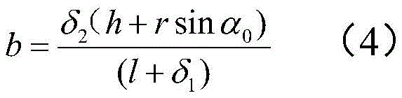
Further, the robot trajectory radius may be determined in the manner shown in fig. 3, wherein for equation (2), the constant a is first determined by the geometric relationship of right triangles:
the constants a and b are determined by the geometric relationship of right triangles, where:
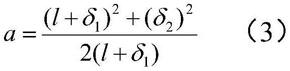

wherein P is 1 And P 2 Representing the two end points of the long bar of the parallelogram mechanism, l representing P 2 Horizontal distance delta from point to outside of robot moving platform 1 、δ 2 Respectively represents the horizontal and vertical distance delta from the P3 point to the outer side of the moving platform of the robot 1 >0,δ 2 >0;P 3 Is a point on a movable track of the parallelogram mechanism with r as a radius; after determining the constant a and the constant b, equation (2) can be re-expressed as a new second order equation for r: m' r 2 +n 'r+p' =0 (5), and further updating the calculation scheme of r, yields:

wherein m ', n ', p ' represent the quadratic term, the first term coefficient, and the constant term of r in the formula (5), respectively.
Specific:


substituting the formulas (6), (7) and (8) into the formula (5) can calculate r (represented by m ', n ', p '):

determining the position relationship between two end points of a long rod of the robot parallelogram mechanism, as shown in fig. 2: the distance between P1 and P2 can be expressed by a formula containing constant parameters:
L 1 =A'+rcosα 0 (10)

the positional relationship between the P1 and P2 points is as follows:

x P1 representing P 1 Point abscissa, x P2 Representing P 2 Point abscissa, z P1 Representing P 1 Point ordinate, z P2 Representing P 2 Point ordinate.
The positional relationship between A, B points is then:

in the embodiment, for each robot, calculating the singular position of the parallelogram mechanism in real time in the extending process of the lifting mechanism S1, and keeping the parallelogram mechanism to avoid the singular position;
for example, as shown in fig. 4, to avoid the singular positions of the parallelogram mechanism, the angle requirement must be satisfied:

the parallelogram mechanism does not exhibit the flat configuration shown in fig. 4 (a) when the mechanism has met the angular requirements from the initial position to the final position. Then γ selects an appropriate angle to satisfy the requirement of equation (14).
In the singular position, the normal vector is represented by gamma The included angle between the horizontal direction and the gamma is kept within the range of: />
 Wherein, alpha is 0 And alpha 1 The angles of the link AB at the two extreme positions are shown, respectively. For example, as shown in FIG. 4 (b), γ is the normal vector +.>
 Horizontal direction of AB->
 An included angle between the two. In order to avoid flattening of the parallelogram structure, γ must be less than pi- α 1 At the same time consider alpha 0 > 0, then the value range of gamma can be derived +.>
In practical application, as shown in fig. 9, a coil spring with proper rigidity is added between the point a and the point B of the parallelogram mechanism for simulation, the spring is in a compressed state in the initial state, and the coil spring provides additional pressure for the end effector, so that the end effector can stably clamp an object; the coil spring, which applies a pulling force to the end effector as it is stretched, may be used to maintain the co-moving robot stable as the end effector lifts the object. The coil springs used generate normal forces due to deformation, exerting additional pressure on the object, keeping it clamped at all times and guaranteeing the overall system stability. In FIG. 9, α and β are each parallelogramThe long side and the short side of the shape mechanism are respectively included with the horizontal line; psi is the included angle between the diagonally connected spring and the vertical direction; f (F) spr The force applied to the spring by the parallelogram mechanism after the spring is connected; f (F) spr,t Is F spr A component in the vertical direction;
the embodiment can verify the feasibility through experiments, for example, the dynamics simulation can be performed by using multi-body dynamics simulation software ADAMS, the process of lifting objects by the collaborative mobile transport robot system is displayed, and the influence of different parameters on the lifting capacity of the collaborative mobile robot is verified and described.
The parameters in the simulation are all equal to or close to the actual physical parameters, and the parameters are set as follows, the static friction coefficient mu between the end effector and the object (rubber/steel) p =0.65; static coefficient of friction mu between wheel and ground (rubber/bitumen) g =0.8; the mass M of the single robot is more than or equal to 80kg;
applying a constant torque on the wheels of the stand-alone robot drives the mobile robot forward and ensures contact between the robot end effector and the payload, providing pressure and lifting force on the object. Dynamics simulation was performed on a co-mobile transport robot using a passive lifting mechanism, simulating the motion of the co-mobile transport robot lifting an object and placing it on a stand-alone robot top platform, fig. 8 shows the motion of the robot successfully lifting an object with a mass of 40kg with high friction contact between the object and the end effector. Dynamics simulation was performed on a co-moving robot using a diagonal coil spring mechanism. Fig. 9 illustrates the principle of simulation by adding a coil spring between points a and B of the parallelogram mechanism: the spring is in a compressed state in the initial state, and the coil spring provides additional pressure for the end effector, so that the end effector can stably clamp an object; the coil spring, which applies a pulling force to the end effector as it is stretched, may be used to maintain the co-moving transport robot stable as the end effector lifts the object. The spring tips are attached to the opposite corners of the parallelogram in order to not apply additional pressure to the rod and cause the connecting rod to bend.
The collaborative mobile transport robot is simulated using an interconnection mechanism, which is to have the single robot end effectors interconnected by a virtual system. The use of an interconnection system between the individual robots, as in fig. 10, ensures that the object can be clamped at different stages and without regard to the risk of slipping of the object. At the same time, using the interconnection mechanism, a single robot is fully capable of lifting and placing a payload on its top platform and has better stability. In this case, the ability of the co-mobile robot to lift an object is limited only by the driving force exerted by the stand-alone robot when the handling mechanism is not activated. In the case of applying a driving force to the parallelogram mechanism, the single robot is able to lift the mass of the object up to the total weight of the single robot used.
In this specification, each embodiment is described in a progressive manner, and identical and similar parts of each embodiment are all referred to each other, and each embodiment mainly describes differences from other embodiments. In particular, for the apparatus embodiments, since they are substantially similar to the method embodiments, the description is relatively simple, and reference is made to the description of the method embodiments for relevant points. The foregoing is merely illustrative of the present invention, and the present invention is not limited thereto, and any changes or substitutions easily contemplated by those skilled in the art within the scope of the present invention should be included in the present invention. Therefore, the protection scope of the present invention should be subject to the protection scope of the claims.
Claims (9)
1. A coordinated mobile transportation system based on multiple robots, characterized in that the system consists of at least 2 robots, a lifting mechanism S1 and a rotating platform S2 are installed on each robot, and the lifting mechanism S1 is installed on the rotating platform S2 of each robot;
the rotary stage S2 includes: the robot comprises a moving platform (1) and a rotating platform (2), wherein the moving platform (1) is fixed on the upper surface of the robot, and the rotating platform (2) is connected with the moving platform (1) through a first rotating shaft;
the lifting mechanism S1 includes: two parallelogram mechanisms, a first end effector support (5), a second end effector support (6) and an effector (7);
wherein, in each parallelogram mechanism, it includes: the device comprises two connecting rods (4) and a base (3) which are parallel to each other, wherein the bottom ends of the two connecting rods (4) are connected with the base (3) through a second rotating shaft so as to form a bottom end rotating joint, and the top ends of the two connecting rods (4) which are parallel to each other are connected with a first end effector bracket (5) through a third rotating shaft so as to form a top end rotating joint;
the first end effector bracket (5) adopts a beam structure vertical to the two parallelogram mechanisms;
one end of the second end effector support (6) is fixed on the first end effector support (5), the other end of the second end effector support is fixedly connected with one side surface of the effector (7), and the other side surface of the effector (7) is used as a contact surface for contacting with a die.
2. A system according to claim 1, characterized in that a short bar (3-1) is fixed between the respective bases (3) of the two parallelogram mechanisms;
the short rod (3-1), the second rotation shaft, the third rotation shaft and the first end effector support (5) are parallel to each other.
3. The system according to claim 2, characterized in that the second end effector support (6) is trapezoidal, the long side of the trapezoid being fixedly connected at one end to one side surface of the effector (7) and the short side of the trapezoid being fixedly connected at one end to the first end effector support (5).
4. A system according to claim 3, characterized in that the contact surface of the actuator (7) is covered with a rigid contact plate, the material of which is rubber or an organically synthetic polymer material; and surface batting and wear-resistant filler are attached to the surface of the rigid contact plate.
5. A multi-robot based collaborative mobile transport method for a multi-robot collaborative mobile transport system, the system including at least 2 robots, the method comprising:
s101, acquiring the mass of a mold to be transported, and determining the maximum total lifting force required by lifting the mold to be transported;
s102, determining the number of robots required for lifting the mold to be transported according to the total lifting force required for lifting the mold to be transported;
s103, controlling the determined number of robots to approach the mold to be transported until the contact surface of the actuator (7) of each robot contacts the mold to be transported, and then controlling the lifting mechanism S1 of each robot to synchronously operate and lift the mold to be transported, wherein the lifting height exceeds the height of the rotating table (2) of the robot;
s104, each robot continues to move towards the mold to be transported until a part of the rotary table (2) of each robot enters the projection of the mold to be transported on the ground, and then the lifting mechanism S1 of each robot is controlled to synchronously operate and descend the mold to be transported until the mold to be transported is contacted with the rotary table (2) of each robot;
s105, rotating the angles of the robots until the motion instantaneous centers of all the robots are consistent.
6. The method according to claim 5, characterized in that in S101 determining the total lifting force required to lift the mould to be transported comprises:
determining the maximum lifting force provided by each robot in the process of lifting the mould to be transported: f (f) m,p,t =μ p f m,p,n =μ p f m,p,t =μ p (=μ g f m,g,n )=μ p (μ g Mg), where f m,p,n Robot of mass M at contact point C m,p Pressure applied to the mold to be transported, mu p Represents the friction coefficient, mu, of the contact surface of the actuator (7) of the robot g Indicating that the wheels of the robot are at contact point C with the ground m,g Is a coefficient of friction of (2);
calculating the total lifting force required for lifting the mould to be transported according to the maximum lifting force provided by each robot in the process of lifting the mould to be transported: m max representing the number of robots required to lift the mould to be transported.
7. The method according to claim 6, characterized in that in S103, after the contact surface of the actuator (7) of the robot is in contact with the mold to be transported, the lifting mechanism S1 is operated synchronously, and in the process of lifting up the mold to be transported, the lifting mechanism S1 is operated synchronously, which comprises the elongation of the lifting mechanism S1 of each robot;
for each robot, in the process of extending the lifting mechanism S1, updating and determining the position relation of two endpoints of a long rod of the parallelogram mechanism in real time;
the length of the long rod in the parallelogram mechanism is equal to the track radius r of the parallelogram mechanism, and is expressed as:

wherein, the calculation mode of r is as follows:
r 2 =(h+rsinα 0 ) 2 +(a+b) 2 (2)
wherein h represents the vertical distance from the robot platform to the ground, alpha 0 The included angle between the long side (AB side) of the parallelogram mechanism and the horizontal line of the robot in the initial state is shown; a. b respectively represent two constants which can be determined by triangle geometry, A, B, C, D respectively represent four corners of a parallelogram, l AB 、l CD 、l AD And l BC The lengths of sides AB, CD, AD and BC of the parallelogram mechanism are shown, respectively.
8. The method as recited in claim 7, further comprising:
the constants a and b are determined by the geometric relationship of right triangles, where:

wherein P is 1 And P 2 Representing the two end points of the long bar of the parallelogram mechanism, l representing P 2 Horizontal distance delta from point to outside of robot moving platform 1 、δ 2 Respectively represent P 3 Horizontal and vertical distance of point to outside of robot moving platform, delta 1 >0,δ 2 >0;P 3 Is a point on a movable track of the parallelogram mechanism with r as a radius; after determining the constant a and the constant b, the calculation mode of r is updated, and the calculation mode can be expressed as a new second-order expression of r: m' r 2 +n 'r+p' =0 (5), yielding:

wherein m ', n ', and p ' represent quadratic terms, primary term coefficients, and constant terms, respectively.
9. The method as recited in claim 6, further comprising:
calculating the singular position of the parallelogram mechanism in real time for each robot in the process of extending the lifting mechanism S1, and keeping the parallelogram mechanism to avoid the singular position;
in the singular position, the normal vector is represented by gamma The included angle between the horizontal direction and the gamma is kept within the range of: />
Wherein, alpha is 0 And alpha 1 The angles of the link AB at the two extreme positions are shown, respectively.
Priority Applications (1)
| Application Number | Priority Date | Filing Date | Title |
|---|---|---|---|
| CN202310334233.4A CN116395382A (en) | 2023-03-30 | 2023-03-30 | Collaborative mobile transportation method and system based on multiple robots |
Applications Claiming Priority (1)
| Application Number | Priority Date | Filing Date | Title |
|---|---|---|---|
| CN202310334233.4A CN116395382A (en) | 2023-03-30 | 2023-03-30 | Collaborative mobile transportation method and system based on multiple robots |
Publications (1)
| Publication Number | Publication Date |
|---|---|
| CN116395382A true CN116395382A (en) | 2023-07-07 |
Family
ID=87009730
Family Applications (1)
| Application Number | Title | Priority Date | Filing Date |
|---|---|---|---|
| CN202310334233.4A Pending CN116395382A (en) | 2023-03-30 | 2023-03-30 | Collaborative mobile transportation method and system based on multiple robots |
Country Status (1)
| Country | Link |
|---|---|
| CN (1) | CN116395382A (en) |
-
2023
- 2023-03-30 CN CN202310334233.4A patent/CN116395382A/en active Pending
Similar Documents
| Publication | Publication Date | Title |
|---|---|---|
| CN107352206B (en) | Sorting device of logistics code-taking system and sorting method thereof | |
| US20100272552A1 (en) | Palletizing robot | |
| WO2016055876A1 (en) | Packaging and gripping group for flat articles, as well as respective method | |
| US20220219317A1 (en) | Robotic system with gripping mechanism | |
| CN110654804A (en) | Automatic loading and unloading system of logistics robot | |
| CN209777705U (en) | Automatic destacking robot capable of preventing dropping | |
| CN112693909B (en) | Industrial Internet is with 5G intelligent transfer robot and use system | |
| US20240246589A1 (en) | Laterally operating payload handling device | |
| JPS61257829A (en) | Robot system for article palletizing | |
| KR101480346B1 (en) | gravity compensation device of vertical articulated robot with a parallel link structure | |
| CN113165171A (en) | Robotic system including articulated arm | |
| US8926260B2 (en) | Agricultural storage container manipulator | |
| CN116395382A (en) | Collaborative mobile transportation method and system based on multiple robots | |
| US10968051B1 (en) | Adjustable robotic end of arm tool for multiple object handling | |
| US20230321846A1 (en) | Robotic systems with object handling mechanism and associated systems and methods | |
| JP7246602B2 (en) | ROBOT SYSTEM WITH GRIP MECHANISM, AND RELATED SYSTEMS AND METHODS | |
| US20230278208A1 (en) | Robotic system with gripping mechanisms, and related systems and methods | |
| JP6976096B2 (en) | Container gripping device | |
| CN107571245A (en) | A kind of numerical control 6DOF parallel institution Minitype swing machine | |
| CN1603216A (en) | Center automatically positioning device for tire stack | |
| US20240189982A1 (en) | Robotic system with object handling mechanism for loading and unloading of cargo carriers | |
| JPH085961Y2 (en) | Robot system for article palletizing | |
| CN117645111A (en) | Humanoid-manipulation type robot heavy-load conveyor and conveying method | |
| EP4410503A1 (en) | Pick-and-place system and method | |
| CN107839202A (en) | A kind of rubber core for torsion bar shock-absorbing sleeve orthopedic equipment |
Legal Events
| Date | Code | Title | Description |
|---|---|---|---|
| PB01 | Publication | ||
| PB01 | Publication | ||
| SE01 | Entry into force of request for substantive examination | ||
| SE01 | Entry into force of request for substantive examination |