CN116290367A - Separated beam column node of assembled steel structure and system thereof - Google Patents
Separated beam column node of assembled steel structure and system thereof Download PDFInfo
- Publication number
- CN116290367A CN116290367A CN202310334269.2A CN202310334269A CN116290367A CN 116290367 A CN116290367 A CN 116290367A CN 202310334269 A CN202310334269 A CN 202310334269A CN 116290367 A CN116290367 A CN 116290367A
- Authority
- CN
- China
- Prior art keywords
- column section
- steel structure
- plate
- foundation
- bolt group
- Prior art date
- Legal status (The legal status is an assumption and is not a legal conclusion. Google has not performed a legal analysis and makes no representation as to the accuracy of the status listed.)
- Pending
Links
- 229910000831 Steel Inorganic materials 0.000 title claims abstract description 92
- 239000010959 steel Substances 0.000 title claims abstract description 92
- 238000010276 construction Methods 0.000 claims abstract description 16
- 238000009434 installation Methods 0.000 claims description 11
- 238000010030 laminating Methods 0.000 claims description 4
- 235000017166 Bambusa arundinacea Nutrition 0.000 claims description 2
- 235000017491 Bambusa tulda Nutrition 0.000 claims description 2
- 241001330002 Bambuseae Species 0.000 claims description 2
- 235000015334 Phyllostachys viridis Nutrition 0.000 claims description 2
- 239000011425 bamboo Substances 0.000 claims description 2
- 230000000694 effects Effects 0.000 abstract 1
- 230000002708 enhancing effect Effects 0.000 abstract 1
- 238000003466 welding Methods 0.000 description 11
- 230000007547 defect Effects 0.000 description 6
- 238000000034 method Methods 0.000 description 6
- 238000005516 engineering process Methods 0.000 description 3
- 238000000926 separation method Methods 0.000 description 3
- 230000000712 assembly Effects 0.000 description 1
- 238000000429 assembly Methods 0.000 description 1
- 239000011324 bead Substances 0.000 description 1
- 238000005452 bending Methods 0.000 description 1
- 230000009286 beneficial effect Effects 0.000 description 1
- 238000009435 building construction Methods 0.000 description 1
- 238000010586 diagram Methods 0.000 description 1
- 238000012986 modification Methods 0.000 description 1
- 230000004048 modification Effects 0.000 description 1
- 230000035515 penetration Effects 0.000 description 1
- 230000003014 reinforcing effect Effects 0.000 description 1
- 230000000087 stabilizing effect Effects 0.000 description 1
- 239000003351 stiffener Substances 0.000 description 1
Images
Classifications
-
- E—FIXED CONSTRUCTIONS
- E04—BUILDING
- E04B—GENERAL BUILDING CONSTRUCTIONS; WALLS, e.g. PARTITIONS; ROOFS; FLOORS; CEILINGS; INSULATION OR OTHER PROTECTION OF BUILDINGS
- E04B1/00—Constructions in general; Structures which are not restricted either to walls, e.g. partitions, or floors or ceilings or roofs
- E04B1/18—Structures comprising elongated load-supporting parts, e.g. columns, girders, skeletons
- E04B1/24—Structures comprising elongated load-supporting parts, e.g. columns, girders, skeletons the supporting parts consisting of metal
- E04B1/2403—Connection details of the elongated load-supporting parts
-
- E—FIXED CONSTRUCTIONS
- E04—BUILDING
- E04B—GENERAL BUILDING CONSTRUCTIONS; WALLS, e.g. PARTITIONS; ROOFS; FLOORS; CEILINGS; INSULATION OR OTHER PROTECTION OF BUILDINGS
- E04B1/00—Constructions in general; Structures which are not restricted either to walls, e.g. partitions, or floors or ceilings or roofs
- E04B1/38—Connections for building structures in general
- E04B1/58—Connections for building structures in general of bar-shaped building elements
- E04B1/5806—Connections for building structures in general of bar-shaped building elements with a cross-section having an open profile
- E04B1/5812—Connections for building structures in general of bar-shaped building elements with a cross-section having an open profile of substantially I - or H - form
-
- E—FIXED CONSTRUCTIONS
- E04—BUILDING
- E04B—GENERAL BUILDING CONSTRUCTIONS; WALLS, e.g. PARTITIONS; ROOFS; FLOORS; CEILINGS; INSULATION OR OTHER PROTECTION OF BUILDINGS
- E04B1/00—Constructions in general; Structures which are not restricted either to walls, e.g. partitions, or floors or ceilings or roofs
- E04B1/38—Connections for building structures in general
- E04B1/58—Connections for building structures in general of bar-shaped building elements
- E04B1/5825—Connections for building structures in general of bar-shaped building elements with a closed cross-section
- E04B1/5831—Connections for building structures in general of bar-shaped building elements with a closed cross-section of substantially rectangular form
-
- E—FIXED CONSTRUCTIONS
- E04—BUILDING
- E04G—SCAFFOLDING; FORMS; SHUTTERING; BUILDING IMPLEMENTS OR AIDS, OR THEIR USE; HANDLING BUILDING MATERIALS ON THE SITE; REPAIRING, BREAKING-UP OR OTHER WORK ON EXISTING BUILDINGS
- E04G21/00—Preparing, conveying, or working-up building materials or building elements in situ; Other devices or measures for constructional work
- E04G21/14—Conveying or assembling building elements
-
- E—FIXED CONSTRUCTIONS
- E04—BUILDING
- E04B—GENERAL BUILDING CONSTRUCTIONS; WALLS, e.g. PARTITIONS; ROOFS; FLOORS; CEILINGS; INSULATION OR OTHER PROTECTION OF BUILDINGS
- E04B1/00—Constructions in general; Structures which are not restricted either to walls, e.g. partitions, or floors or ceilings or roofs
- E04B1/18—Structures comprising elongated load-supporting parts, e.g. columns, girders, skeletons
- E04B1/24—Structures comprising elongated load-supporting parts, e.g. columns, girders, skeletons the supporting parts consisting of metal
- E04B1/2403—Connection details of the elongated load-supporting parts
- E04B2001/2406—Connection nodes
-
- E—FIXED CONSTRUCTIONS
- E04—BUILDING
- E04B—GENERAL BUILDING CONSTRUCTIONS; WALLS, e.g. PARTITIONS; ROOFS; FLOORS; CEILINGS; INSULATION OR OTHER PROTECTION OF BUILDINGS
- E04B1/00—Constructions in general; Structures which are not restricted either to walls, e.g. partitions, or floors or ceilings or roofs
- E04B1/18—Structures comprising elongated load-supporting parts, e.g. columns, girders, skeletons
- E04B1/24—Structures comprising elongated load-supporting parts, e.g. columns, girders, skeletons the supporting parts consisting of metal
- E04B1/2403—Connection details of the elongated load-supporting parts
- E04B2001/2418—Details of bolting
-
- Y—GENERAL TAGGING OF NEW TECHNOLOGICAL DEVELOPMENTS; GENERAL TAGGING OF CROSS-SECTIONAL TECHNOLOGIES SPANNING OVER SEVERAL SECTIONS OF THE IPC; TECHNICAL SUBJECTS COVERED BY FORMER USPC CROSS-REFERENCE ART COLLECTIONS [XRACs] AND DIGESTS
- Y02—TECHNOLOGIES OR APPLICATIONS FOR MITIGATION OR ADAPTATION AGAINST CLIMATE CHANGE
- Y02E—REDUCTION OF GREENHOUSE GAS [GHG] EMISSIONS, RELATED TO ENERGY GENERATION, TRANSMISSION OR DISTRIBUTION
- Y02E10/00—Energy generation through renewable energy sources
- Y02E10/50—Photovoltaic [PV] energy
Landscapes
- Engineering & Computer Science (AREA)
- Architecture (AREA)
- Civil Engineering (AREA)
- Structural Engineering (AREA)
- Physics & Mathematics (AREA)
- Electromagnetism (AREA)
- Mechanical Engineering (AREA)
- Joining Of Building Structures In Genera (AREA)
Abstract
The invention discloses a separated beam column node of an assembled steel structure and a system thereof, which comprise column sections, connecting pieces and beams, wherein the column sections comprise steel structure columns, upper and lower end connecting interfaces and beam interfaces, the connecting pieces comprise steel structure columns, backing plates and steel members, the beams are I-shaped steel beams with bolt through holes at two ends, and all the parts are connected through full bolt matching, so that the assembly relation is simplified, standardized and convenient to operate, and the construction efficiency is improved. According to the invention, the positions of the connecting points of the beam and the column are separated, so that the connection of the beam and column nodes is converted from single nodes to double nodes, the stress of the connecting nodes is dispersed, and the effects of enhancing the strength, the rigidity and the stability of the connecting nodes are achieved.
Description
Technical Field
The invention belongs to the technical field of assembly type steel structure construction, and particularly relates to a separation type beam column node of an assembly type steel structure and a system thereof.
Background
At present, the green and environment-friendly assembled building is being promoted greatly in China, the assembled steel structure is an important component part in the assembled building, and the characteristics of short construction period and high construction efficiency are incomparable with the traditional building technology, so that the connection node of the assembled steel structure is particularly important, and the performance of the connection node directly influences the strength, the rigidity and the stability of a steel structure system. However, at present, the steel structure connecting nodes in China are mainly used for assembling and fixedly connecting beam and column members through a welding process, certain errors and defects exist in welding, the requirements on welding seam quality and construction process are very strict, quality is not easy to control, mechanical properties of the nodes are easy to influence, the beam and column nodes are usually concentrated at one position, stress conditions are complex, and the existing assembled steel structure still has a large problem for large-span buildings, high-rise buildings and buildings greatly influenced by geographical conditions such as earthquake, typhoon and the like.
There are two general ways of welding conventional steel columns and beams in the field: a full penetration bead is adopted; the other is a double-sided fillet weld or a K-groove weld. The connection modes are low in construction speed, weld quality is difficult to guarantee, errors are easy to generate, defects are caused, and mechanical properties of the nodes are further affected.
Therefore, different assembly type steel structure beam column node connection methods appear in the prior art, and the main connection methods are as follows:
the first prior art is: the utility model discloses a beam column node that assembled steel construction interpolation board square steel tubular column splint connect of chinese invention patent application that the application publication is 2019.10.22, application publication number is CN110359555A, includes: the invention discloses a beam column node for connecting square steel column clamping plates of an assembled steel structure interpolation plate, which comprises a lower column module, an upper column module, a beam module and clamping plates, wherein the lower column module is formed by welding a lower column, a ribbed supporting plate, an inner inserting plate and stiffening ribs in a factory, the upper column module is formed by welding an upper column and a ribbed supporting plate in the factory, the beam module is formed by welding an H-shaped steel beam and stiffening ribs in the factory, and reserved parts of the upper column, the H-shaped steel beam, the inner inserting plate, the ribbed supporting plate and the clamping plates are provided with holes and are transported to the site for full bolt assembly.
And the second prior art is as follows: the assembled steel structure beam column node structure disclosed in China patent application with the application publication number of CN214784820U and the application publication date of 2021.11.19 comprises: the steel structure column, install in the polylith base plate on the steel structure column side and install in each I-steel on the base plate is provided with on each the base plate be used for with the fixing bolt that the steel structure column is connected, each the base plate is provided with two bedplate, two be provided with between the bedplate and supply the clearance that the I-steel passed, the web of I-steel with two install a plurality of bolts between the bedplate.
In the prior art, although the on-site full bolt assembly is realized in the prior art, a large number of complex assemblies still need to finish welding work in advance, errors and defects are easy to generate, repeated on-site installation operation is caused, and time is wasted. The I-steel is fixedly installed on the steel structure column body in the first and second technologies, no additional welding work is needed on site by workers, but forces of the upper column body, the lower column body and the cross beam in the node structure are concentrated at one position, the stress condition is complex, and the mechanical property of the connecting node is easily affected.
Therefore, how to simply, accurately, quickly and conveniently connect the beam column joints of the assembled steel structure and strengthen the strength, the rigidity and the stability of the beam column joints of the assembled steel structure is a primary technical problem to be solved.
Disclosure of Invention
Aiming at the defects in the background technology, the invention provides a separated beam column node of an assembled steel structure and a system thereof, which solve the technical problems of single stress point, influenced mechanical property, low construction efficiency and easy error and defect in the construction process of the existing steel structure node.
The technical scheme of the invention is as follows:
the utility model provides an assembled steel construction beam column node that adoption separation node is connected, includes vertical node and transverse node, the height of transverse node is less than the height of vertical node, vertical node includes upper column section and lower column section that links to each other through the connecting piece, transverse node includes lower column section and the crossbeam that links to each other through the connecting piece.
Furthermore, the upper column section, the lower column section, the connecting piece and the cross beam are connected through full bolts, and the construction site can be completed only by assembling workers.
Further, the connecting piece is connected with the upper column section through a first bolt connecting structure, the first bolt connecting structure comprises a box-shaped cylinder core inserted between the upper column section and the lower column section, and the box-shaped cylinder core is sleeved and attached to the inner walls of the upper column section and the lower column section; the periphery of the box-type cylinder core is provided with a base plate; the lower port of the upper column section is provided with a flange interface corresponding to the backing plate, and the backing plate is connected with the flange interface through a first vertical bolt group.
Further, the first bolt connection structure further comprises a first auxiliary bolt group connected between the box cylinder core and the upper column section, the first auxiliary bolt group penetrates through the overlapping part of the box cylinder core and the upper column section, and a stiffening rib is arranged on a flange interface of the upper column section.
Further, the connecting piece is connected with the lower column section through a second bolt connection structure, the second bolt connection structure comprises a horizontal stiffening rib arranged at the upper end part of the lower column section, the horizontal stiffening rib is connected with the base plate and the flange interface through a first vertical bolt group, a positioning notch is formed in the side wall of the upper end part of the lower column section, a vertical stiffening rib is arranged between the horizontal stiffening rib and the outer side wall of the lower column section, the base plate is connected with a side steel member in plug-in fit with the positioning notch, and the side steel member is connected with the vertical stiffening rib through a transverse bolt group.
Further, the second bolt connection structure further comprises a second auxiliary bolt group connected between the box cylinder core and the lower column section, and the second auxiliary bolt group penetrates through the overlapping part of the box cylinder core and the lower column section.
Further, the side steel member includes concave board one, concave board two of controlling relative setting, concave board one and concave board two parallel arrangement and the interval of surface with the width of location notch is the same, be provided with the connecting plate between concave board one and the concave board two, be provided with the strip stiffening rib of support between concave board one and concave board two on the outer wall laminating, the outer wall of connecting plate and the outer wall of box section of thick bamboo core, connect on the top of connecting plate in backing plate, bottom and location notch laminating, concave board one, concave board two, location notch length are the same.
Further, a bottom plate is arranged between the bottoms of the first concave plate and the second concave plate, a bearing platform is arranged on the lower column section, stiffening ribs are arranged below the bearing platform, a cross beam is connected between the bearing platform and the bottom plate, the upper flange of the cross beam is connected with the bottom plate through a second vertical bolt group, and the lower flange of the cross beam is connected with the bearing platform through a third vertical bolt group
An assembled steel structure system, comprising the separated beam column node of the assembled steel structure and the following steps:
step one: the fixed foundation column section can be divided into two modes: firstly, pre-burying bolts on a concrete foundation in advance, and fixing the bolts and a foundation column section in the concrete foundation after the concrete is solidified to realize the fixedly connection of the bolts and the foundation column section; the second is to directly place the foundation column section on the foundation before pouring the foundation concrete, and pour the foundation column section together with the components such as the steel bars in the foundation, and fix the foundation column section after the concrete is solidified;
step two: after the lower column section is arranged on the foundation section, a bearing platform on the lower column section is arranged, a cross beam is lifted, when the lower flange of the cross beam and the bearing platform are lifted to the same horizontal height, the cross beam is horizontally moved, the lower flange of the cross beam is attached to the bearing platform, and the lower flange of the cross beam is fixed through a second vertical bolt group;
step three: lifting the connecting piece to the upper part of the lower column Duan Zheng, slowly falling along the vertical direction, enabling the side steel member on the connecting piece to be clamped into the positioning notch of the lower column section, continuing falling until the side steel member is completely embedded into the positioning notch, attaching the concave plate to the vertical stiffening rib, fixing the concave plate through the transverse bolt group, attaching the bottom plate to the upper flange of the cross beam, and fixedly connecting the concave plate to the upper flange of the cross beam through the vertical bolt group II;
step four: lifting an upper column section to be connected, lifting the upper column section to be right above a connecting piece, descending the upper column section along the vertical direction until a box-type cylinder core of the connecting piece is inserted into the upper column section, attaching the surface of the box-type cylinder core to the inner surface of the column section, attaching a flange interface of the upper column section, a backing plate of the connecting piece to a horizontal stiffening rib of the lower column section, and fixedly connecting the flange interface, the backing plate and the horizontal stiffening rib of the lower column section through a first vertical bolt group;
step five: and (3) repeating the first step to the fourth step for same-layer installation until the installation of the steel structure of one layer is completed, and repeating the second step to the fourth step for layer-by-layer installation until the installation of the top layer is completed.
The invention has the following specific beneficial effects:
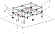
1. according to the assembled steel structure Liang Zhujie point which is connected by the separation node, the positions of the connecting points of the column body and the cross beam are separated, the upper column section and the lower column section are connected by the vertical node, the lower column section and the cross beam are connected by the transverse node, the transverse node is positioned below the vertical node, and the connection of the beam column nodes is converted from single node to double node, so that the firmness between the beam columns is ensured, the connection between the column columns is reinforced, the stress of the connecting nodes is dispersed, a plurality of connecting nodes are not arranged at the same position, and the strength, the rigidity and the stability of the connecting nodes are enhanced.
2. The assembled steel structure beam column node and the system simplify and standardize parts to be assembled of each part, the construction site can be completed only by performing full bolt assembly by workers, errors and defects caused by welding are avoided, the assembly relation is effectively standardized, the operation is simple, the construction progress is greatly accelerated, the efficiency problem in the building construction process is improved, new choices are provided for some projects to be completed rapidly, and the application range is wide.
Drawings
In order to more clearly illustrate the embodiments of the present invention, the drawings that are required for the description of the embodiments will be briefly described below, it being apparent that the drawings in the following description are only some embodiments of the present invention and that other drawings may be obtained from these drawings without inventive effort for a person of ordinary skill in the art.
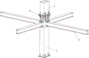
FIG. 1 is a schematic perspective view of an assembled steel structure beam column joint;
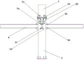
FIG. 2 is an elevation view of a fabricated steel structure beam column node;
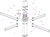
FIG. 3 is an exploded view of an assembled steel structure beam column node;
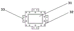
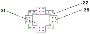
FIG. 4 is a top view of a fabricated steel structure beam column node connector;
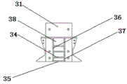
FIG. 5 is a side view of a fabricated steel structure beam column node connector;
FIG. 6 is a bottom view of a fabricated steel structure beam column node connector;
fig. 7 is a schematic diagram of an assembled steel structure system.
Reference numerals illustrate:
1. an upper column section; 2. a lower column section; 3. a connecting piece; 4. a cross beam;
11. a flange interface; 12. stiffening ribs;
22. positioning the notch; 23. vertical stiffening ribs; 24. horizontal stiffening ribs;
31. a box-type cylinder core; 32. a backing plate; 33. a side steel member; 34. a strip stiffener; 35. a bottom plate; 36. concave plate I; 37. concave plate II; 38. a connecting plate;
51. bearing platform; 52. bearing platform stiffening ribs;
62. a first vertical bolt group;
72. an auxiliary bolt group I; 74. an auxiliary bolt group II;
82. a transverse bolt group;
92. a second vertical bolt group; 94. and a vertical bolt group III.
Detailed Description
The following description of the embodiments of the present invention will be made clearly and completely with reference to the accompanying drawings, in which it is apparent that the embodiments described are only some embodiments of the present invention, but not all embodiments. All other embodiments, which can be made by those skilled in the art based on the embodiments of the invention without any inventive effort, are intended to be within the scope of the invention.
The utility model provides a disconnect-type beam column node of assembled steel construction, includes vertical node and transverse node, the height of transverse node is less than the height of vertical node, vertical node includes upper column section 1 and lower column section 2 that link to each other through connecting piece 3, transverse node includes lower column section 3 and crossbeam 4 that link to each other through connecting piece 3. According to the technical scheme, the positions of the connecting points of the columns and the cross beams are separated, the connection of the beam column nodes is converted into double nodes from single nodes, so that the firmness between the beams and the columns is guaranteed, the connection between the columns and the columns is reinforced, the stress of the connecting nodes is dispersed, a plurality of connecting nodes are not arranged at the same position, and the strength, the rigidity and the stability of the connecting nodes are enhanced. In the prior art of the node described in the background art, forces of the upper column body, the lower column body and the cross beam are concentrated at one position, the stress condition is complex, and the mechanical property of the connecting node is greatly influenced.
As a preferred implementation mode of the separated beam column node of the assembled steel structure, the connecting piece 3 is connected with the upper column section 1, the lower column section 2 and the cross beam 4 in a bolt fit manner, and the construction site can be completed only by assembling workers.
As a preferred implementation mode of the separated beam column joint of the assembled steel structure, the connecting piece 3 is connected with the upper column section 1 through a first bolt connection structure, the first bolt connection structure comprises a box-shaped cylinder core 31 inserted between the upper column section 1 and the lower column section 2, the box-shaped cylinder core 31 is preferably hollow rectangular or polygonal, the box-shaped cylinder core 31 is sleeved and attached to the inner walls of the upper column section 1 and the lower column section 2, the shapes of the box-shaped cylinder core 31 and the upper column section 1 and the lower column section 2 are unified, a backing plate 32 integrated by welding or pouring is arranged at the position Zhou Pianshang outside the box-shaped cylinder core 31, a flange interface 11 corresponding to the backing plate 32 is arranged at the lower port of the upper column section 1, the backing plate 32 is connected with the flange interface 11 through a first vertical bolt group 62, and the increase of the number of bolts is arranged in the first vertical bolt group 62, so that the stability between the upper column section and the connecting piece can be effectively enhanced.
As a preferred embodiment of the split beam-column joint of the fabricated steel structure, the first bolt connection structure further comprises a first auxiliary bolt set 72 connected between the box-shaped cylinder core 31 and the upper column section 1, the first auxiliary bolt set 72 penetrates through the overlapping part of the box-shaped cylinder core 31 and the upper column section 1, the first auxiliary bolt set 72 can be arranged on two or more opposite sides of the box-shaped cylinder core 31, and stability between the upper column section 1 and the connecting piece 3 can be effectively enhanced. The stiffening ribs 12 arranged on the periphery of the lower connector of the upper column section 1 also play a role in reinforcing the strength of the flange connector 11, and the increase of the number of the stiffening ribs 12 increases the firmness of the flange connector 11 and the upper column section 1.
As a preferred implementation mode of the separated beam column node of the assembled steel structure, the connecting piece 3 is connected with the lower column section 2 through a second bolt connection structure, the second bolt connection structure comprises a horizontal stiffening rib 24 arranged at the upper end part of the lower column section, the horizontal stiffening rib 24 is connected with the backing plate 32 and the flange interface 11 through a first vertical bolt group 62, the side wall of the upper end part of the lower column section 2 is provided with a positioning notch 22, a vertical stiffening rib 23 is arranged between the horizontal stiffening rib 24 and the outer side wall of the lower column section 2, and the increase of the number of the vertical stiffening ribs 23 plays a role of stabilizing the node. The backing plate 32 is connected with a side steel member 33 which is in plug-in fit with the positioning notch 22, and the side steel member 33 is connected with the vertical stiffening rib 23 through a transverse bolt group 82.
As a preferred embodiment of the split beam column node of the fabricated steel structure, the second bolt connection structure further comprises a second auxiliary bolt set 74 connected between the box-shaped cylinder core 31 and the lower column section 2, and the second auxiliary bolt set 74 can be arranged on two or more opposite sides of the box-shaped cylinder core 31, and penetrates through the overlapping part of the box-shaped cylinder core 31 and the lower column section 2, so that the connection between the lower column section 2 and the node of the connecting piece 3 is effectively reinforced; the increased number of bolts provided in the second set of auxiliary bolts 74 can effectively enhance stability between the lower column section and the connecting member.
As a preferred embodiment of the split beam column joint of the fabricated steel structure, the side steel member 33 includes a first concave plate 36 and a second concave plate 37 which are oppositely disposed left and right, the first concave plate 36 and the second concave plate 37 are disposed in parallel, and the interval between the outer surfaces is the same as the width of the positioning notch 22; a connecting plate 38 is arranged between the first concave plate 36 and the second concave plate 37, the inner wall of the connecting plate 38 is attached to the outer wall of the box cylinder core 31, single or multiple strip stiffening ribs 34 supported between the first concave plate 36 and the second concave plate 37 are arranged on the outer wall, the single or multiple strip stiffening ribs 34 are uniformly distributed on the connecting plate 38, and the increase of the number can effectively strengthen the side steel member 33; the top end of the connecting plate 38 is connected with the backing plate 32, and the bottom end is attached to the positioning notch 22; the first concave plate 36, the second concave plate 37 and the positioning notch 22 have the same length, so as to better fit the connection relationship between the nodes.
As a preferred implementation mode of the separated beam column joint of the assembled steel structure, a bottom plate 35 is arranged between the bottom ends of the first concave plate 36 and the second concave plate 37 and is used for connecting a beam top flange, a bearing platform 51 is arranged on the lower column section 2 and is used for connecting a beam bottom flange, bearing platform stiffening ribs 52 are arranged below the bearing platform 51, the increase of the number of the bearing platform stiffening ribs 52 also can strengthen the tensile resistance and the bending resistance of the bearing platform 51, a beam 4 is connected between the bearing platform 51 and the bottom plate 35, the beam 4 is an I-shaped steel beam, the beam 4 top flange is connected with the bottom plate 35 through a second vertical bolt group 92, the beam 4 bottom flange is connected with the bearing platform 51 through a third vertical bolt group 94, and the increase of the number of the vertical bolt group 92 and the third vertical bolt group 94 can effectively strengthen the connection firmness between the beam 4 and the lower column section 2.
An assembled steel structure system, comprising the separated beam column node of the assembled steel structure and the following steps:
step one: the fixed foundation column section can be divided into two modes: firstly, pre-burying bolts on a concrete foundation in advance, and fixing the bolts and a foundation column section through the bolts in the concrete foundation after the concrete is solidified to realize the fixation of the bolts and the foundation column section; the second is to directly place the foundation column section on the foundation before pouring the foundation concrete, and pour the foundation column section together with the components such as the steel bars in the foundation, and fix the foundation column section after the concrete is solidified;
step two: after the lower column section is arranged on the foundation section, a bearing platform on the lower column section is arranged, a cross beam is lifted, when the lower flange of the cross beam and the bearing platform are lifted to the same horizontal height, the cross beam is horizontally moved, the lower flange of the cross beam is attached to the bearing platform, and the lower flange of the cross beam is fixed through a second vertical bolt group;
step three: lifting the connecting piece to the upper part of the lower column Duan Zheng, slowly falling along the vertical direction, enabling the side steel member on the connecting piece to be clamped into the positioning notch of the lower column section, continuing falling until the side steel member is completely embedded into the positioning notch, attaching the concave plate to the vertical stiffening rib, fixing the concave plate through the transverse bolt group, attaching the bottom plate to the upper flange of the cross beam, and fixedly connecting the concave plate to the upper flange of the cross beam through the vertical bolt group II;
step four: lifting an upper column section to be connected, lifting the upper column section to be right above a connecting piece, descending the upper column section along the vertical direction until a box-type cylinder core of the connecting piece is inserted into the upper column section, attaching the surface of the box-type cylinder core to the inner surface of the column section, attaching a flange interface of the upper column section, a backing plate of the connecting piece to a horizontal stiffening rib of the lower column section, and fixedly connecting the flange interface, the backing plate and the horizontal stiffening rib of the lower column section through a first vertical bolt group;
step five: and after the first to fourth steps are repeated to finish the installation of the one-layer steel structure, the second to fourth steps are repeated to finish the installation of the top layer, and the top layer column section only has a lower end connecting port.
The present invention is not limited to the conventional technical means known to those skilled in the art.
The foregoing has shown and described the basic principles, main features and advantages of the present invention. The foregoing description of the preferred embodiments of the invention is not intended to be limiting, but rather is intended to cover all modifications, equivalents, alternatives, and improvements that fall within the spirit and scope of the invention.
Claims (10)
1. The utility model provides a disconnect-type beam column node of assembled steel construction which characterized in that: the vertical node comprises an upper column section (1) and a lower column section (2) which are connected through a connecting piece (3), and the transverse node comprises a lower column section (2) and a cross beam (4) which are connected through the connecting piece (3).
2. The split beam-column joint of fabricated steel structure according to claim 1, wherein: the connecting pieces (3) are connected with the upper column section (1), the lower column section (2) and the cross beam (4) through bolts.
3. The split beam-column joint of fabricated steel structure according to claim 1 or 2, wherein: the connecting piece (3) is connected with the upper column section (1) through a first bolt connection structure, the first bolt connection structure comprises a box-shaped cylinder core (31) inserted between the upper column section (1) and the lower column section (2), the box-shaped cylinder core (31) is sleeved and attached to the inner walls of the upper column section (1) and the lower column section (2), a base plate (32) is arranged on the periphery of the box-shaped cylinder core (31), a flange interface (11) corresponding to the base plate (32) is arranged at the lower port of the upper column section (1), and the base plate (32) is connected with the flange interface (11) through a first vertical bolt group (62).
4. A split beam-column joint of fabricated steel structure as claimed in claim 3, wherein: the first bolt connecting structure further comprises a first auxiliary bolt group (72) connected between the box cylinder core (31) and the upper column section (1), the first auxiliary bolt group (72) penetrates through the overlapping part of the box cylinder core (31) and the upper column section (1), and stiffening ribs (12) are arranged on a flange interface (11) of the upper column section (1).
5. The split beam-column joint of fabricated steel structure according to claim 4, wherein: the connecting piece (3) is connected with the lower column section (2) through a second bolt connection structure, the second bolt connection structure comprises a horizontal stiffening rib (24) arranged at the upper end part of the lower column section (2), the horizontal stiffening rib (24) is connected with a backing plate (32) and a flange interface (11) through a first vertical bolt group (62), a positioning notch (22) is formed in the side wall of the upper end part of the lower column section (2), a vertical stiffening rib (23) is arranged between the horizontal stiffening rib (24) and the outer side wall of the lower column section (2), the backing plate (32) is connected with a side steel member (33) which is in plug-in fit with the positioning notch (22), and the side steel member (33) is connected with the vertical stiffening rib (23) through a transverse bolt group (82).
6. The fabricated steel structure split beam-column node of claim 5, wherein: the second bolt connecting structure further comprises a second auxiliary bolt group (74) connected between the box cylinder core (31) and the lower column section (2), and the second auxiliary bolt group (74) penetrates through the overlapping part of the box cylinder core (31) and the lower column section (2).
7. The split beam-column joint of fabricated steel structure according to claim 5 or 6, wherein: the side steel member (33) is including controlling concave board one (36), concave board two (37) of relative setting, concave board one (36) and concave board two (37) parallel arrangement and the interval of surface with the width of location notch (22) is the same, be provided with connecting plate (38) between concave board one (36) and concave board two (37), be provided with on the outer wall laminating of inner wall and box section of thick bamboo core (31) of connecting plate (38), support strip stiffening rib (34) between concave board one (36) and concave board two (37), connect on the top of connecting plate (38) in backing plate (32), bottom and location notch (22) laminating, concave board one (36), concave board two (37), location notch (22) length are all the same.
8. The split beam-column joint of fabricated steel structure according to claim 7, wherein: bottom plate (35) is arranged between the bottom ends of concave plate one (36) and concave plate two (37), a bearing platform (51) is arranged on the lower column section (2), stiffening ribs (52) are arranged below the bearing platform (51), a cross beam is connected between the bearing platform (51) and the bottom plate (35), an upper flange of the cross beam (4) is connected with the bottom plate (35) through a vertical bolt group two (92), and a lower flange of the cross beam (4) is connected with the bearing platform (51) through a vertical bolt group three (94).
9. An assembled steel structure system, characterized in that: a split beam-column joint comprising the fabricated steel structure of any one of claims 1-8.
10. The fabricated steel structural system according to claim 9, comprising the steps of:
step one: the fixed foundation column section can be divided into two modes: firstly, pre-burying bolts on a concrete foundation in advance, and fixing the bolts and a foundation column section through the bolts in the concrete foundation after the concrete is solidified to realize the fixation of the bolts and the foundation column section; the second is to directly place the foundation column section on the foundation before pouring the foundation concrete, and pour the foundation column section together with the components such as the steel bars in the foundation, and fix the foundation column section after the concrete is solidified;
step two: the bearing platform on the lower column section is installed, the cross beam is lifted, when the lower flange of the cross beam and the bearing platform are lifted to the same horizontal height, the cross beam is horizontally moved, the lower flange of the cross beam is attached to the bearing platform, and the lower flange of the cross beam is fixed through the second vertical bolt group;
step three: lifting the connecting piece to the upper part of the lower column Duan Zheng, slowly falling along the vertical direction, enabling the side steel member on the connecting piece to be clamped into the positioning notch of the lower column section, continuing falling until the side steel member is completely embedded into the positioning notch, attaching the concave plate to the vertical stiffening rib, fixing the concave plate through the transverse bolt group, attaching the bottom plate to the upper flange of the cross beam, and fixedly connecting the concave plate to the upper flange of the cross beam through the vertical bolt group II;
step four: lifting an upper column section to be connected, lifting the upper column section to be right above a connecting piece, descending the upper column section along the vertical direction until a box-type cylinder core of the connecting piece is inserted into the upper column section, attaching the surface of the box-type cylinder core to the inner surface of the column section, attaching a flange interface of the upper column section, a backing plate of the connecting piece to a horizontal stiffening rib of the lower column section, and fixedly connecting the flange interface, the backing plate and the horizontal stiffening rib of the lower column section through a first vertical bolt group;
step five: and (3) repeating the first step to the fourth step for same-layer installation until the installation of the steel structure of one layer is completed, and repeating the second step to the fourth step for layer-by-layer installation until the installation of the top layer is completed.
Priority Applications (1)
| Application Number | Priority Date | Filing Date | Title |
|---|---|---|---|
| CN202310334269.2A CN116290367A (en) | 2023-03-31 | 2023-03-31 | Separated beam column node of assembled steel structure and system thereof |
Applications Claiming Priority (1)
| Application Number | Priority Date | Filing Date | Title |
|---|---|---|---|
| CN202310334269.2A CN116290367A (en) | 2023-03-31 | 2023-03-31 | Separated beam column node of assembled steel structure and system thereof |
Publications (1)
| Publication Number | Publication Date |
|---|---|
| CN116290367A true CN116290367A (en) | 2023-06-23 |
Family
ID=86834232
Family Applications (1)
| Application Number | Title | Priority Date | Filing Date |
|---|---|---|---|
| CN202310334269.2A Pending CN116290367A (en) | 2023-03-31 | 2023-03-31 | Separated beam column node of assembled steel structure and system thereof |
Country Status (1)
| Country | Link |
|---|---|
| CN (1) | CN116290367A (en) |
-
2023
- 2023-03-31 CN CN202310334269.2A patent/CN116290367A/en active Pending
Similar Documents
| Publication | Publication Date | Title |
|---|---|---|
| CN107288218B (en) | Beam column node of assembled reinforced concrete frame structure and manufacturing method thereof | |
| CN104712089A (en) | Open web composite shear connector construction | |
| RU2548627C2 (en) | Steel frame structure with usage of u-shaped composite beam | |
| KR101713863B1 (en) | the rigid connection structure between precast concrete column and precast concrete beam using the temporary bracket installing precast concrete column, the modular system using the same | |
| CN109184030B (en) | Assembly type concrete shear wall superposed structure system and installation method | |
| CN113931324A (en) | Cross steel rib column full-bolt rigid connection node and construction method | |
| CN111119336A (en) | Y-shaped vertical face intersection conversion node formed by welding box-type steel pipes and application | |
| KR101547540B1 (en) | Hybrid beam having different type flange | |
| CN219316021U (en) | Steel construction building plate body structure and connected node | |
| CN108457374A (en) | A kind of box beam and column are linked and packed formula node preparation process and its node | |
| CN209114604U (en) | One kind is for rolling girder steel and the rigidly connected node structure of steel column and Housing Structure System | |
| CN111021616A (en) | Full-embedded steel beam composite floor and construction method thereof | |
| CN114575451B (en) | Construction method of assembled reinforced concrete frame | |
| CN114215179B (en) | Wet construction method for center pillar joint of steel beam floor system and steel frame wallboard system | |
| CN116290367A (en) | Separated beam column node of assembled steel structure and system thereof | |
| CN113431187B (en) | Layered assembly type beam column node | |
| CN115262834A (en) | A steel bar truss floor carrier plate integrated configuration for LOFT apartment interlayer is built | |
| CN212317480U (en) | Multi-story high-rise assembled steel structure non-composite floor slab supporting system | |
| CN114215181A (en) | Steel beam floor system and steel frame wallboard system center pillar joint dry-type construction method | |
| CN209780036U (en) | Rectangular column of foundation layer of prefabricated building and prefabricated building | |
| CN210164280U (en) | Node is installed additional to stand on girder steel | |
| CN110607743A (en) | Full-bolt connection type honeycomb type multilayer H-shaped steel bridge structure and assembling method thereof | |
| CN111910914A (en) | Multi-story high-rise assembled steel structure non-composite floor slab supporting system and construction method thereof | |
| CN219240890U (en) | Square steel tubular column and H-shaped steel beam assembled type connecting node | |
| CN215211577U (en) | Beam column node structure easy to build |
Legal Events
| Date | Code | Title | Description |
|---|---|---|---|
| PB01 | Publication | ||
| PB01 | Publication | ||
| SE01 | Entry into force of request for substantive examination | ||
| SE01 | Entry into force of request for substantive examination |