CN116281426A - Coiling device for cable production - Google Patents
Coiling device for cable production Download PDFInfo
- Publication number
- CN116281426A CN116281426A CN202211721892.5A CN202211721892A CN116281426A CN 116281426 A CN116281426 A CN 116281426A CN 202211721892 A CN202211721892 A CN 202211721892A CN 116281426 A CN116281426 A CN 116281426A
- Authority
- CN
- China
- Prior art keywords
- cable
- assembly
- coil
- coiling
- winding
- Prior art date
- Legal status (The legal status is an assumption and is not a legal conclusion. Google has not performed a legal analysis and makes no representation as to the accuracy of the status listed.)
- Pending
Links
- 238000004519 manufacturing process Methods 0.000 title claims abstract description 16
- 230000007246 mechanism Effects 0.000 claims abstract description 73
- 230000009471 action Effects 0.000 claims abstract description 6
- 238000004804 winding Methods 0.000 claims description 34
- 230000001105 regulatory effect Effects 0.000 claims description 8
- 230000005540 biological transmission Effects 0.000 claims description 6
- 238000007599 discharging Methods 0.000 claims 9
- 238000000926 separation method Methods 0.000 claims 3
- 230000000694 effects Effects 0.000 claims 1
- 238000000034 method Methods 0.000 description 3
- 238000006243 chemical reaction Methods 0.000 description 2
- 230000008569 process Effects 0.000 description 2
- 229910000838 Al alloy Inorganic materials 0.000 description 1
- 230000009286 beneficial effect Effects 0.000 description 1
- 239000004020 conductor Substances 0.000 description 1
- 238000005516 engineering process Methods 0.000 description 1
- 238000009434 installation Methods 0.000 description 1
- 230000004048 modification Effects 0.000 description 1
- 238000012986 modification Methods 0.000 description 1
- 239000011241 protective layer Substances 0.000 description 1
Images
Classifications
-
- B—PERFORMING OPERATIONS; TRANSPORTING
- B65—CONVEYING; PACKING; STORING; HANDLING THIN OR FILAMENTARY MATERIAL
- B65H—HANDLING THIN OR FILAMENTARY MATERIAL, e.g. SHEETS, WEBS, CABLES
- B65H67/00—Replacing or removing cores, receptacles, or completed packages at paying-out, winding, or depositing stations
- B65H67/04—Arrangements for removing completed take-up packages and or replacing by cores, formers, or empty receptacles at winding or depositing stations; Transferring material between adjacent full and empty take-up elements
- B65H67/0405—Arrangements for removing completed take-up packages or for loading an empty core
-
- B—PERFORMING OPERATIONS; TRANSPORTING
- B65—CONVEYING; PACKING; STORING; HANDLING THIN OR FILAMENTARY MATERIAL
- B65H—HANDLING THIN OR FILAMENTARY MATERIAL, e.g. SHEETS, WEBS, CABLES
- B65H54/00—Winding, coiling, or depositing filamentary material
- B65H54/02—Winding and traversing material on to reels, bobbins, tubes, or like package cores or formers
- B65H54/40—Arrangements for rotating packages
- B65H54/44—Arrangements for rotating packages in which the package, core, or former is engaged with, or secured to, a driven member rotatable about the axis of the package
-
- B—PERFORMING OPERATIONS; TRANSPORTING
- B65—CONVEYING; PACKING; STORING; HANDLING THIN OR FILAMENTARY MATERIAL
- B65H—HANDLING THIN OR FILAMENTARY MATERIAL, e.g. SHEETS, WEBS, CABLES
- B65H75/00—Storing webs, tapes, or filamentary material, e.g. on reels
- B65H75/02—Cores, formers, supports, or holders for coiled, wound, or folded material, e.g. reels, spindles, bobbins, cop tubes, cans, mandrels or chucks
- B65H75/04—Kinds or types
- B65H75/08—Kinds or types of circular or polygonal cross-section
- B65H75/14—Kinds or types of circular or polygonal cross-section with two end flanges
-
- B—PERFORMING OPERATIONS; TRANSPORTING
- B65—CONVEYING; PACKING; STORING; HANDLING THIN OR FILAMENTARY MATERIAL
- B65H—HANDLING THIN OR FILAMENTARY MATERIAL, e.g. SHEETS, WEBS, CABLES
- B65H2701/00—Handled material; Storage means
- B65H2701/30—Handled filamentary material
- B65H2701/34—Handled filamentary material electric cords or electric power cables
Landscapes
- Coiling Of Filamentary Materials In General (AREA)
Abstract
The invention discloses a coiling device for cable production, which comprises a coiling mechanism and a coil unloading mechanism, wherein the coiling mechanism comprises a support and a coiling assembly arranged on the support, the coil unloading mechanism comprises a front driving mechanism, a rear driving mechanism, a rotation driving mechanism and a coil unloading assembly, the front driving mechanism and the rear driving mechanism are provided with the rotation driving mechanism, the coil unloading assembly is driven by the rotation driving mechanism to be sleeved on the coiling assembly or separated from the coiling assembly under the action of the front driving mechanism and the rear driving mechanism, the coil unloading assembly comprises two annular baffle plates, the coiling assembly between the two annular baffle plates is used for coiling a cable, and the two annular baffle plates can rotate along with the coiling assembly.
Description
[ field of technology ]
The invention relates to the technical field of cable production, in particular to the technical field of a coiling device for cable production.
[ background Art ]
Cable definition: is made of one or more mutually insulated conductors and an outer insulating protective layer, and is used for transmitting power or information from one place to another place.
The winder is one of the cable production devices, and is mainly used for winding cables, so that the cables are convenient to package and transport.
The application number is: the invention of CN201810701168.3 discloses an automatic disc changer for producing aluminum alloy cables, the output ends of a first wire winding motor and a second wire winding motor of the application are respectively provided with a wire winding shaft opposite to the other side end of a conversion disc, the upper ends of the wire winding shafts are sleeved with wire coils, wire clamping grooves are respectively formed in the positions, close to the edges, of the two sides of the upper ends of the wire coils, one end, close to the conversion disc, of the wire winding shafts is sleeved with a first baffle, one end, far from the first baffle, of the wire winding shaft is sleeved with a second baffle, the wire coils are positioned between the first baffle and the second baffle, the wire coils are convenient to fix, the wire coils rotate stably, the disassembly and assembly of the wire coils are finished by the existing manual operation, and therefore, the manual workload is increased, and the wire winding device is inconvenient to use.
[ invention ]
The invention aims to solve the problems in the prior art and provides a coiling device for cable production, which can reduce the manual workload and is convenient to use.
In order to achieve the above purpose, the invention provides a coiling device for cable production, which comprises a coiling mechanism and a coil stripping mechanism, wherein the coiling mechanism comprises a support and a coiling assembly arranged on the support, the coil stripping mechanism comprises a front driving mechanism and a rear driving mechanism, a rotation driving mechanism and a coil stripping assembly, the front driving mechanism and the rear driving mechanism are provided with the rotation driving mechanism, the rotation driving mechanism drives the coil stripping assembly to be sleeved on the coiling assembly or separated from the coiling assembly under the action of the front driving mechanism and the rear driving mechanism, the coil stripping assembly comprises two annular baffle plates, the coiling assembly between the two annular baffle plates is used for coiling a cable, and the two annular baffle plates can rotate along with the coiling assembly.
Preferably, the winding assembly comprises a speed regulating motor, an air expansion shaft, a plurality of connecting bodies I and a plurality of supporting bodies, wherein the driving end of the speed regulating motor is in transmission connection with one end of the air expansion shaft, the air expansion shaft is provided with a plurality of convex key strips which are uniformly arranged in a circumferential shape, the outer ends of the convex key strips are respectively provided with the connecting bodies I, and one ends, far away from the convex key strips, of the connecting bodies I are respectively provided with the supporting bodies.
Preferably, the coil stripping assembly further comprises two guide rods, a mounting seat, an electric push rod, a fixed ring seat, a movable ring seat and a support, wherein the guide rods are arranged on the mounting seat, the fixed ring seat is arranged at the rear end of the guide rods, the electric push rod is arranged at the rear end of the mounting seat, the support is arranged at the driving end of the electric push rod, the movable ring seat which is arranged on the guide rods in a sliding manner is arranged on the support, and the two annular baffle discs are respectively arranged on the inner sides of the fixed ring seat and the movable ring seat in a rotating manner.
Preferably, the front-back driving mechanism comprises a servo motor and a ball screw sliding table, and the driving end of the servo motor is in transmission connection with a screw of the ball screw sliding table.
Preferably, the rotation driving mechanism comprises a base, a worm gear box and a rotating motor, wherein the worm gear box is arranged on the base, the rotating motor is arranged on the worm gear box, and the driving end of the rotating motor is fixedly connected with the input end of the worm gear box.
Preferably, the device further comprises a conveying belt and a pushing mechanism, wherein the pushing mechanism is positioned behind the conveying belt and used for pushing the cable roll on the coil unloading assembly onto the conveying belt.
Preferably, the pushing mechanism comprises an electric cylinder and a pushing plate arranged on the driving end of the electric cylinder.
Preferably, the cable fixing device is used for fixing the cut-off end of the cable on the winding assembly, and comprises an anti-falling body, a fixing ring and a connecting body II arranged between the anti-falling body and the fixing ring, wherein the fixing ring can deform under the action of external force and keep the current state.
The invention has the beneficial effects that: according to the invention, the two annular baffle discs are sleeved on the winding assembly, the winding assembly between the two annular baffle discs is used for winding a cable, after the winding is completed, the rotary driving mechanism drives the coil stripping assembly to separate from the winding assembly under the action of the front and rear driving mechanisms, the cable wound on the winding assembly is dismounted, and after the cable coil on the coil stripping assembly is taken away, the coil stripping assembly is sleeved on the winding assembly again to continue the winding of the cable. Compared with the prior art, the manual work load can be reduced, and the use is convenient.
The features and advantages of the present invention will be described in detail by way of example with reference to the accompanying drawings.
[ description of the drawings ]
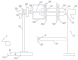
FIG. 1 is a schematic view of a cable production coiling apparatus according to the present invention;
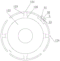
FIG. 2 is a partial side view of the winding assembly;
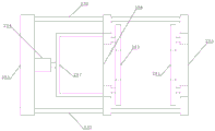
fig. 3 is a schematic structural view of the coil-stripping assembly.
In the figure: 1-winding mechanism, 2-coil-unloading mechanism, 3-conveyer belt, 4-pushing mechanism, 5-cable fixing piece, 11-support, 12-winding assembly, 21-back driving mechanism, 22-rotation driving mechanism, 23-coil-unloading assembly, 41-electric cylinder, 42-pushing plate, 51-anti-drop body, 52-fixing ring, 53-connector II, 121-speed regulating motor, 122-inflatable shaft, 123-connector I, 124-support body, 125-male key bar, 231-annular baffle disc, 232-guide rod, 233-installation seat, 234-electric push rod, 235-fixed ring seat, 236-movable ring seat, 237-support, 211-servo motor, 212-ball screw sliding table, 221-seat body, 222-worm gear box and 223-rotating motor.
[ detailed description ] of the invention
Referring to fig. 1, 2 and 3, a coiling device for producing cables of the present invention comprises a coiling mechanism 1 and a coil unloading mechanism 2, wherein the coiling mechanism 1 comprises a support 11 and a coiling assembly 12 arranged on the support 11, the coil unloading mechanism 2 comprises a front driving mechanism 21, a rear driving mechanism 22 and a coil unloading assembly 23, the front driving mechanism 21 is provided with a rotation driving mechanism 22, the rotation driving mechanism 22 is provided with a coil unloading assembly 23, the rotation driving mechanism 22 drives the coil unloading assembly 23 to be sleeved on the coiling assembly 12 or separated from the coiling assembly 12 under the action of the front driving mechanism 21, the coil unloading assembly 23 comprises two annular baffle discs 231, the coiling assembly 12 between the two annular baffle discs 231 is used for coiling cables, the two annular baffle discs 231 can rotate along with the coiling assembly 12, the winding assembly 12 comprises a speed regulating motor 121, an air expansion shaft 122, a plurality of connecting bodies I123 and a plurality of supporting bodies 124, wherein the driving end of the speed regulating motor 121 is in transmission connection with one end of the air expansion shaft 122, the air expansion shaft 122 is provided with a plurality of convex key strips 125 which are uniformly arranged in a circumferential shape, the outer ends of the convex key strips 125 are respectively provided with the connecting bodies I123, one ends of the connecting bodies I123 far away from the convex key strips 125 are respectively provided with the supporting bodies 124, the coil stripping assembly 23 further comprises two guide rods 232, a mounting seat 233, an electric push rod 234, a fixed ring seat 235, a movable ring seat 236 and a bracket 237, the mounting seat 233 is provided with a guide rod 232, the rear end of the guide rod 232 is provided with a fixed ring seat 235, the rear end of the mounting seat 233 is provided with the electric push rod 234, the driving end of the electric push rod 234 is provided with the bracket 237, the bracket 237 is provided with the movable ring seat 236 which is arranged on the guide rod 232 in a sliding way, the two annular baffle discs 231 are respectively arranged on the inner sides of the fixed ring seat 235 and the movable ring seat 236 in a rotating mode, the front-rear driving mechanism 21 comprises a servo motor 211 and a ball screw sliding table 212, the driving end of the servo motor 211 is in transmission connection with the lead screw of the ball screw sliding table 212, the rotating driving mechanism 22 comprises a seat body 221, a worm gear box 222 and a rotating motor 223, the seat body 221 is provided with the worm gear box 222, the worm gear box 222 is provided with the rotating motor 223, the driving end of the rotating motor 223 is fixedly connected with the input end of the worm gear box 222, the front-rear driving mechanism further comprises a conveying belt 3 and a pushing mechanism 4, the pushing mechanism 4 is positioned behind the conveying belt 3 and used for pushing a cable roll on the unreeling assembly 23 onto the conveying belt 3, the pushing mechanism 4 comprises an electric cylinder 41 and a pushing plate 42 arranged on the driving end of the electric cylinder 41, the cable fixing piece 5 is further comprises a cable cutting end fixed on the reeling assembly 12, and the cable fixing piece 5 comprises a release preventing body 51, a fixing ring 52 and a deformation preventing body 52 can be kept under the current state of the connection state of the release body 52.
The working process of the invention comprises the following steps:
in the working process of the coiling device for producing the cable, a cable fixing piece 5 is clamped between two adjacent supporting bodies 124, an anti-falling body 51 is positioned at the inner side of the two adjacent supporting bodies 124, a fixing ring 52 is positioned at the outer side of the two adjacent supporting bodies 124, the cable is inserted into the fixing ring 52, then the fixing ring 52 is clamped by pliers to deform, the deformed fixing ring 52 clamps and fixes the cable, then an air expansion shaft 122 is driven by a speed regulating motor 121 to rotate to coil the cable, after the coiling is completed, the cable is cut off, an electric push rod 234 is started to drive a movable ring seat 236 to move backwards through a bracket 237, the movable ring seat 236 drives an annular baffle disc 231 on the movable ring seat 236 to move backwards to clamp the cable coil, then the air expansion shaft 122 is exhausted, the supporting bodies 124 are led to move towards the air expansion shaft 122, the support of the cable coil is relieved, then a servo motor 211 is started to drive a ball screw sliding table 212 to act, the ball screw sliding table 212 drives the coil stripping assembly 23 to move forwards through the rotation driving mechanism 22, the coil stripping assembly 23 removes the cable coil from the winding assembly 12, then the rotating motor 223 is started to drive the coil stripping assembly 23 to rotate clockwise for 90 degrees through the worm gear box 222, then the electric push rod 234 is started to drive the movable ring seat 236 to move upwards through the support 237, the movable ring seat 236 drives the annular baffle disc 231 on the movable ring seat to move upwards to release the clamping of the cable coil, then the electric cylinder 41 is started to drive the push plate 42 to move forwards, the push plate 42 pushes the cable coil to enter the conveyor belt 3 from between the two annular baffle discs 231, the conveyor belt 3 conveys the cable coil to enter the next procedure, then the electric cylinder 41 is started to drive the push plate 42 to return, then the rotating motor 223 is started to drive the coil stripping assembly 23 to rotate anticlockwise for 90 degrees through the worm gear box 222, then, the servo motor 211 is started to drive the ball screw sliding table 212 to act, the ball screw sliding table 212 drives the coil unloading assembly 23 to move backwards through the rotation driving mechanism 22, the coil unloading assembly 23 is sleeved on the supporting body 124 again, then the inflatable shaft 122 is inflated, the corresponding supporting body 124 is driven by the convex key strip 125 to move away from the inflatable shaft 122 through the connecting body I123, the supporting body 124 is supported on the inner ring of the annular baffle disc 231, and then the winding work can be performed again.
The above embodiments are illustrative of the present invention, and not limiting, and any simple modifications of the present invention fall within the scope of the present invention.
Claims (8)
1. The utility model provides a lapping device of cable production which characterized in that: including winding mechanism (1) and coil discharging mechanism (2), winding mechanism (1) include support (11) and establish winding assembly (12) on support (11), coil discharging mechanism (2) are including front and back actuating mechanism (21), rotation actuating mechanism (22) and coil discharging subassembly (23), be equipped with rotation actuating mechanism (22) on front and back actuating mechanism (21), be equipped with coil discharging subassembly (23) on rotation actuating mechanism (22), rotation actuating mechanism (22) drive coil discharging subassembly (23) cover and establish on winding assembly (12) or break away from winding assembly (12) under the effect of front and back actuating mechanism (21), coil discharging subassembly (23) include two annular separation discs (231), winding assembly (12) between two annular separation discs (231) are used for the coiling of cable, two annular separation discs (231) can rotate along with winding assembly (12).
2. A cable production coiling device as in claim 1, wherein: the winding assembly (12) comprises a speed regulating motor (121), an air expansion shaft (122), a plurality of connecting bodies I (123) and a plurality of supporting bodies (124), wherein the driving end of the speed regulating motor (121) is in transmission connection with one end of the air expansion shaft (122), the air expansion shaft (122) is provided with a plurality of convex key strips (125) which are uniformly arranged in a circumferential shape, the outer ends of the convex key strips (125) are respectively provided with the connecting bodies I (123), and one ends, far away from the convex key strips (125), of the connecting bodies I (123) are respectively provided with the supporting bodies (124).
3. A cable production coiling device as in claim 1, wherein: the coil discharging assembly (23) further comprises two guide rods (232), a mounting seat (233), an electric push rod (234), a fixed ring seat (235), a movable ring seat (236) and a support (237), wherein the guide rods (232) are arranged on the mounting seat (233), the fixed ring seat (235) is arranged at the rear end of the guide rods (232), the electric push rod (234) is arranged at the rear end of the mounting seat (233), the support (237) is arranged at the driving end of the electric push rod (234), the support (237) is provided with the movable ring seat (236) which is arranged on the guide rods (232) in a sliding mode, and the two annular baffle discs (231) are respectively arranged on the inner sides of the fixed ring seat (235) and the movable ring seat (236) in a rotating mode.
4. A cable production coiling device as in claim 1, wherein: the front-back driving mechanism (21) comprises a servo motor (211) and a ball screw sliding table (212), and the driving end of the servo motor (211) is connected with the screw rod of the ball screw sliding table (212) in a transmission manner.
5. A cable production coiling device as in claim 1, wherein: the rotary driving mechanism (22) comprises a base body (221), a worm gear box (222) and a rotary motor (223), wherein the worm gear box (222) is arranged on the base body (221), the rotary motor (223) is arranged on the worm gear box (222), and the driving end of the rotary motor (223) is fixedly connected with the input end of the worm gear box (222).
6. A cable production coiling device as in claim 1, wherein: the automatic coil discharging device further comprises a conveying belt (3) and a pushing mechanism (4), wherein the pushing mechanism (4) is located behind the conveying belt (3) and used for pushing the cable coil on the coil discharging assembly (23) onto the conveying belt (3).
7. A cable production coiling device as in claim 6, wherein: the pushing mechanism (4) comprises an electric cylinder (41) and a pushing plate (42) arranged on the driving end of the electric cylinder (41).
8. A coiling device for producing electrical cables as in any one of claims 1 to 7, characterized in that: the novel cable winding device is characterized by further comprising a cable fixing piece (5) used for fixing the cut-off end of the cable on the winding assembly (12), wherein the cable fixing piece (5) comprises an anti-falling body (51), a fixing ring (52) and a connecting body II (53) arranged between the anti-falling body (51) and the fixing ring (52), and the fixing ring (52) can deform and keep the current state under the action of external force.
Priority Applications (1)
| Application Number | Priority Date | Filing Date | Title |
|---|---|---|---|
| CN202211721892.5A CN116281426A (en) | 2022-12-30 | 2022-12-30 | Coiling device for cable production |
Applications Claiming Priority (1)
| Application Number | Priority Date | Filing Date | Title |
|---|---|---|---|
| CN202211721892.5A CN116281426A (en) | 2022-12-30 | 2022-12-30 | Coiling device for cable production |
Publications (1)
| Publication Number | Publication Date |
|---|---|
| CN116281426A true CN116281426A (en) | 2023-06-23 |
Family
ID=86827614
Family Applications (1)
| Application Number | Title | Priority Date | Filing Date |
|---|---|---|---|
| CN202211721892.5A Pending CN116281426A (en) | 2022-12-30 | 2022-12-30 | Coiling device for cable production |
Country Status (1)
| Country | Link |
|---|---|
| CN (1) | CN116281426A (en) |
Cited By (1)
| Publication number | Priority date | Publication date | Assignee | Title |
|---|---|---|---|---|
| CN118125217A (en) * | 2024-05-07 | 2024-06-04 | 杭州鸿世电器股份有限公司 | Winding type electric wire winding disc |
-
2022
- 2022-12-30 CN CN202211721892.5A patent/CN116281426A/en active Pending
Cited By (1)
| Publication number | Priority date | Publication date | Assignee | Title |
|---|---|---|---|---|
| CN118125217A (en) * | 2024-05-07 | 2024-06-04 | 杭州鸿世电器股份有限公司 | Winding type electric wire winding disc |
Similar Documents
| Publication | Publication Date | Title |
|---|---|---|
| CN116281426A (en) | Coiling device for cable production | |
| CN117383311B (en) | Photovoltaic solder strip auxiliary production equipment and method | |
| CN211957443U (en) | Wire winding and feeding mechanism with fixed-point paint stripping function | |
| CN117854923A (en) | Speed-adjustable transformer winder and winding method thereof | |
| CN209691575U (en) | A kind of amorphous Triangular Three Dimensional Wound Core tinsel cord automatic winding mechanism | |
| CN114883108A (en) | Transformer winding platform for charger and control system thereof | |
| CN115188582A (en) | Method and device for winding continuous cake-shaped coil | |
| CN211016764U (en) | Single-shaft winding device for transformer | |
| CN221057262U (en) | Automatic fly line twisting device for transformer | |
| CN221739523U (en) | Winding device for processing thick cable | |
| CN220786261U (en) | Full-automatic cable wire packing apparatus | |
| CN219916796U (en) | Stranded wire equipment for cable production | |
| CN215047614U (en) | Wire take-up machine | |
| CN219708726U (en) | Automatic tangent line disc-changing device of oxygen-free copper wire | |
| CN220510942U (en) | Shaping device is cup jointed with silicon steel sheet to stator core | |
| CN118380922B (en) | Cable stripping equipment for cables | |
| CN114408666B (en) | Automatic wire unloading device for copper wire winding disc | |
| CN217650595U (en) | Automatic reciprocating winding device for insulated electromagnetic wire of high-power generator | |
| CN118107838B (en) | Automatic cable packing equipment | |
| CN221708548U (en) | Winding machine for reactor coil | |
| CN116779322B (en) | Automatic change paster inductance coiling machine | |
| CN221500179U (en) | Conveyer is used in cable conductor production | |
| CN217498086U (en) | Insulating paper winding equipment | |
| CN217035266U (en) | Stranded conductor device of production cable | |
| CN217858559U (en) | Pressure spring machine that centre gripping is firm |
Legal Events
| Date | Code | Title | Description |
|---|---|---|---|
| PB01 | Publication | ||
| PB01 | Publication | ||
| SE01 | Entry into force of request for substantive examination | ||
| SE01 | Entry into force of request for substantive examination |