CN116275278A - Sawing method of double-head cutting saw with 45-degree angle for door and window frame section bar - Google Patents
Sawing method of double-head cutting saw with 45-degree angle for door and window frame section bar Download PDFInfo
- Publication number
- CN116275278A CN116275278A CN202211704512.7A CN202211704512A CN116275278A CN 116275278 A CN116275278 A CN 116275278A CN 202211704512 A CN202211704512 A CN 202211704512A CN 116275278 A CN116275278 A CN 116275278A
- Authority
- CN
- China
- Prior art keywords
- vertical
- cylinder
- workbench
- horizontal
- pressing
- Prior art date
- Legal status (The legal status is an assumption and is not a legal conclusion. Google has not performed a legal analysis and makes no representation as to the accuracy of the status listed.)
- Pending
Links
Images


Classifications
-
- B—PERFORMING OPERATIONS; TRANSPORTING
- B23—MACHINE TOOLS; METAL-WORKING NOT OTHERWISE PROVIDED FOR
- B23D—PLANING; SLOTTING; SHEARING; BROACHING; SAWING; FILING; SCRAPING; LIKE OPERATIONS FOR WORKING METAL BY REMOVING MATERIAL, NOT OTHERWISE PROVIDED FOR
- B23D45/00—Sawing machines or sawing devices with circular saw blades or with friction saw discs
- B23D45/14—Sawing machines or sawing devices with circular saw blades or with friction saw discs for cutting otherwise than in a plane perpendicular to the axis of the stock, e.g. for making a mitred cut
-
- B—PERFORMING OPERATIONS; TRANSPORTING
- B23—MACHINE TOOLS; METAL-WORKING NOT OTHERWISE PROVIDED FOR
- B23D—PLANING; SLOTTING; SHEARING; BROACHING; SAWING; FILING; SCRAPING; LIKE OPERATIONS FOR WORKING METAL BY REMOVING MATERIAL, NOT OTHERWISE PROVIDED FOR
- B23D47/00—Sawing machines or sawing devices working with circular saw blades, characterised only by constructional features of particular parts
- B23D47/04—Sawing machines or sawing devices working with circular saw blades, characterised only by constructional features of particular parts of devices for feeding, positioning, clamping, or rotating work
-
- B—PERFORMING OPERATIONS; TRANSPORTING
- B23—MACHINE TOOLS; METAL-WORKING NOT OTHERWISE PROVIDED FOR
- B23D—PLANING; SLOTTING; SHEARING; BROACHING; SAWING; FILING; SCRAPING; LIKE OPERATIONS FOR WORKING METAL BY REMOVING MATERIAL, NOT OTHERWISE PROVIDED FOR
- B23D59/00—Accessories specially designed for sawing machines or sawing devices
-
- Y—GENERAL TAGGING OF NEW TECHNOLOGICAL DEVELOPMENTS; GENERAL TAGGING OF CROSS-SECTIONAL TECHNOLOGIES SPANNING OVER SEVERAL SECTIONS OF THE IPC; TECHNICAL SUBJECTS COVERED BY FORMER USPC CROSS-REFERENCE ART COLLECTIONS [XRACs] AND DIGESTS
- Y02—TECHNOLOGIES OR APPLICATIONS FOR MITIGATION OR ADAPTATION AGAINST CLIMATE CHANGE
- Y02P—CLIMATE CHANGE MITIGATION TECHNOLOGIES IN THE PRODUCTION OR PROCESSING OF GOODS
- Y02P70/00—Climate change mitigation technologies in the production process for final industrial or consumer products
- Y02P70/10—Greenhouse gas [GHG] capture, material saving, heat recovery or other energy efficient measures, e.g. motor control, characterised by manufacturing processes, e.g. for rolling metal or metal working
Abstract
The invention discloses a sawing method of a double-head cutting saw with a 45-degree angle of a door and window frame fan profile, when the profile is cut, the profile is clamped on a horizontal workbench and a vertical workbench on a left sawing machine head and a right sawing machine head, when the profile is cut, a saw blade is perpendicular to the horizontal workbench, the included angle between the saw blade and the vertical workbench is 45 degrees, the mounting surface of the frame material profile is abutted against the vertical workbench, the bonding area with the workbench is large, the profile is not easy to slip when the profile is cut, the cutting length of the profile on the cutting saw is the framing length of the profile, the material height of the profile does not need to be measured before the profile is cut, and the cutting efficiency and the cutting precision are improved. The double-head cutting saw comprises a left sawing machine head fixedly arranged on a lathe bed and a right sawing machine head slidably arranged on the lathe bed, wherein the left sawing machine head and the right sawing machine head comprise a horizontal workbench, a vertical workbench, a section bar clamping device, a sawing motor, a saw blade and a work feeding mechanism; the saw blades of the left sawing machine head and the right sawing machine head are vertical to the horizontal workbench, and the included angle between the saw blades and the vertical workbench is 45 degrees.
Description
Technical Field
The invention relates to sawing equipment, in particular to a sawing method of a double-head cutting sawing machine for cutting an aluminum profile at an angle of 45 degrees, and belongs to the technical field of aluminum alloy door and window processing equipment.
Background
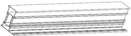
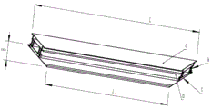
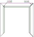
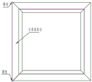
In the door and window processing process, the profile is required to be cut into aluminum profiles with different lengths, different angles and end surface shapes which are consistent with the size of the door and window, then the door and window is assembled, and when the door and window is assembled, the end surfaces of the two profiles are contacted, so that the door and window with high quality is assembled, and the requirements on the length of the profile and the roughness of the end surfaces are very high. The window and door section bar middle frame fan section bar quantity is biggest, in order to improve work efficiency and guarantee aluminum product both ends cutting angle's uniformity, adopts the double-end cutting saw to cut aluminum product generally, can realize that the both ends of section bar cut 45 degrees inclined planes on an equipment, dock two adjacent aluminum products into 90 angles, carries out the corner combining processing on the corner combining machine at last, connects into an holistic frame construction with the frame section bar through the angle sign indicating number. Fig. 1 is a schematic diagram of a broken bridge aluminum alloy door and window frame material, fig. 2 is a schematic diagram of a frame material with two ends cut into 45-degree inclined planes, a surface a is a window frame mounting surface corresponding to a door/window opening on a building, a surface b is a glass or fan mounting surface, a surface c is an outdoor surface (facing out of the building), a surface d is an indoor surface (facing indoors), an included angle between the 45-degree inclined plane and the surface a is 45 degrees, an included angle between the 45-degree inclined plane and the surface b is 135 degrees, and an included angle between the inclined plane and the surfaces c and d is 90 degrees. The main factors influencing the cornification of the door and window assembly are the precision of the angle of the 45-degree inclined plane after the section bar is cut, the perpendicularity of the 45-degree inclined plane and the c and d planes, the precision of the length L of the mounting surface and the surface roughness of the 45-degree inclined plane; gaps can be formed on the c surface or the d surface after the 45-degree inclined surface is not perpendicular to the c surface and the d surface (see figure 3), and the error angle of two angles can be formed after the angle is formed when the accuracy of the length L of the mounting surface is not enough (the length of the right frame material is larger than that of the left frame material) (see figure 4), so that the appearance of a finished product is influenced, the water tightness and the air tightness are also influenced, and the gaps of the angle can be large if the surface state of the 45-degree inclined surface is rough, so that the appearance, the water tightness and the air tightness are further influenced. The accuracy of the angle of the 45-degree bevel is usually fixed by adjusting the angle of the horizontal table and the vertical table with respect to the advancing direction of the cutting saw blade when the initial state of the apparatus is adjusted. The perpendicularity of the 45-degree inclined plane and the c and d planes, the accuracy of the length L of the mounting surface and the surface state of the 45-degree inclined plane are affected by factors such as a cutting method.
The working principle and the structure of the existing double-head saw are relatively mature, and the double-head saw mainly comprises a sawing machine head, a lathe bed, a material supporting frame, a control cabinet and the like. The double-head saw comprises two saw cutting heads, wherein a left saw cutting head is a fixed head, a right saw cutting head is a movable head, and the left saw cutting head and the right saw cutting head can move left and right on a guide rail. The two sawing machine heads have basically the same structure and generally consist of a saw blade, a saw blade motor, a workbench and a pressing device, when the sawing machine is used, firstly, the distance between the two machine heads is accurately adjusted according to the length of an aluminum profile to be cut, then the aluminum profile is placed on the workbench, and the aluminum profile is pressed and fixed through the pressing device; the saw blade motor drives the saw blade to rotate, the saw blade motor is arranged on the motor seat and driven by the feeding cylinder, and the feeding movement of the saw blade is realized in a translational or swinging mode, so that the section bar with the required length and the end face shape is obtained. After the saw blade cuts off the profile, a smooth profile cutting end face can be obtained, but when the saw blade returns along a cutting track, saw teeth of the saw blade can be contacted with the cut smooth profile end face again due to small jumping of the saw blade and vibration of the lathe bed, so that rough cutting marks appear on the profile end face, return stroke sweeping of the saw teeth in the industry is realized, and the phenomenon that return stroke sweeping is avoided in a cutting mode of returning according to the original sawing track.
The double-end cutting saw that uses at present has straight line feeding formula and swing feeding formula according to the worker's mode of saw bit, according to the angle difference of saw bit and horizontal table divide into outer swing angle formula (the contained angle of saw bit and horizontal table is 135 degrees) and interior swing angle formula (the contained angle of saw bit and horizontal table is 45 degrees), interior swing angle double-end saw is because saw cut back waste head and is located saw bit upper portion, can adhere to and collapse out easily on the saw bit, if do not increase waste clamping device, easily lead to the incident, consequently, make its application limited, patent CN106799518B discloses a double-end cutting sawing machine for cutting aluminium alloy 45 degrees, including fixed aircraft nose and movable aircraft nose, install support frame (20) on movable aircraft nose (5), be fixed with horizontal table (21) and vertical table (22) on support frame (20), install saw bit (23) on horizontal table (21), saw bit (23) are installed on saw cut motor (24), saw cut motor (24) are fixed on slide (25), slide (25) are installed on slide (26) through the slider, be connected with worker's air inlet cylinder (27). The patent adopts a technical scheme of an inner swing angle type and a linear feeding type.
The current wide use is outer pendulum angle formula double-end cutting saw, like the automatic double-end saw of outer pendulum formula that patent CN210817585U discloses, all be connected with rotatory box (1) on right aircraft nose (14) and the left aircraft nose (15), and processing platform has been seted up to rotatory box (1) one side level, two hydraulic cylinder (11) are installed perpendicularly respectively with the level on the processing platform, and perpendicular pneumatic clamp (5) and side pneumatic clamp (6) that are connected respectively with two hydraulic cylinder (11) are installed to rotatory box (1) homonymy, install gas-liquid conversion jar (10) in rotatory box (1) homonymy upper end, and be connected with saw cut motor swing arm mechanism (2) on gas-liquid conversion jar (10), saw fixedly connected with direct-connected precision cutting motor (8) on motor swing arm mechanism (2), and install saw bit (13) on direct-connected precision cutting motor (8). The patent adopts the technical scheme of external swing angle type plus swing feeding type.
In the prior art, no matter the saw blade is externally-swinging-angle type, internally-swinging-angle type, linearly-feeding type and swinging-feeding type, the working direction of the saw blade is vertical to a vertical workbench, and a saw notch is formed in the vertical workbench; the section bar to be cut is tightly pressed on the horizontal workbench and the vertical workbench, and when the saw blade works in, the saw blade stretches out of the saw cutting opening to cut the section bar. When the saw blade is of an outward swing angle type structure, the frame material shown in fig. 2 is required to be obtained, the c surface of the section bar is required to be attached to a vertical workbench during cutting, the a surface is on the upper side, and the b surface is on the lower side for cutting; the cutting length on a double-ended cutting saw is usually set at the distance between the intersection of the two saw blades with the plane on the horizontal table, which is represented by the profile length L1 in fig. 2, whereas the profile length required for actual installation is L. The reason is that the size of the opening of the first wall body is consistent with the L size; and the L size of the finished product is convenient to measure. The material height B of the profile must therefore be taken into account when determining the framing length L of the 45-angle profile, i.e. l=l1+2b, which requires measuring the material height of the profile before the profile is cut, which is prone to relatively large measuring errors by hand measurement. The length precision of the section bar cutting is directly influenced by the error value of the material height measurement, and the length precision of the cut section bar directly influences the quality of doors and windows. For this reason, an automatic measuring device for material height has been designed, for example, an aluminum-type material height measuring device disclosed in patent CN210818749U, and the material height is measured by a magnetic grating ruler, so that manual measurement errors are avoided. But either manual or automatic measurement devices can reduce the cutting efficiency.
It can also be seen from fig. 2 that a lap surface contacting with a fan extends from one side of the c surface to one side of the b surface of the profile, when the profile is cut on a workbench, only the side edge of the lap surface contacts with the horizontal workbench, when the vertical pressing device presses the a surface from top to bottom, the profile is difficult to press on the horizontal workbench, the profile is easy to slip and generate position offset when being cut, the cutting precision (angle precision, perpendicularity precision and surface roughness) is reduced, and if the vertical pressing device applies too much force, the profile is easy to deform.
In addition, the shortest length of finished product materials which can be processed by the existing double-head cutting saw is that the right sawing machine head is adjusted to the length corresponding to the distance between the two saw blades when the right sawing machine head is nearest to the left sawing machine head, and ultra-short materials cannot be cut.
In brief, at present, the double-end cutting saw for aluminum door and window profiles is basically characterized in that the fixed machine head and the movable machine head are mainly arranged at the outer swing angle, and the movable machine head can automatically move at fixed length to finally process a workpiece with given length and given end face angle value. In the aluminum door and window industry, the numerical control double-head cutting saw is widely used for section bar blanking. However, the problems that 1, the cut section is not tightly pressed and is easy to slip to generate position deviation, so that the cutting precision is reduced still exist; 2. the material height is required to be measured before cutting, so that the cutting efficiency is reduced; 3. returning according to the original sawing track after the saw blade cuts the profile, and sweeping materials in a return stroke to cause the roughness of the cut end surface of the profile; 4. the ultra-short material cannot be cut.
Along with the increasing of the living standard of people and the requirements of national energy conservation and emission reduction policies, the requirements on the quality of doors and windows are higher. The cutting precision (angle precision, perpendicularity precision and surface roughness) of the existing equipment can not meet the requirements of high-quality doors and windows.
Disclosure of Invention
The invention aims to overcome the defects of the prior art and provide a sawing method of a double-head cutting saw with a 45-degree angle for door and window frame section bars, so as to solve the related problems in the prior art.
The technical scheme adopted by the invention for achieving the purpose is as follows:
a sawing method of a double-head cutting saw for door and window frame section bars with an angle of 45 degrees is characterized in that: the method adopts a double-head cutting saw with 45-degree angle for sawing the door and window frame sash section bar, and comprises the following specific steps:
s1: manually placing the blank profile on a horizontal workbench, leaning the mounting surface of the profile against a vertical workbench, and fitting the outer side surface of the profile on the horizontal workbench;
s2, clamping the profile by a profile clamping device;
the double-head cutting saw for the door and window frame fan section bar with the angle of 45 degrees comprises a lathe bed, wherein a left sawing machine head and a right sawing machine head are arranged on the lathe bed, and the right sawing machine head is arranged on the lathe bed in a sliding manner; the left sawing machine head and the right sawing machine head comprise a horizontal workbench, a vertical workbench, a section bar clamping device, a sawing motor, a saw blade and a working mechanism, wherein the sawing motor drives the saw blade to rotate, and the saw blade is vertical to the horizontal workbench and forms an included angle of 45 degrees with the vertical workbench; the right sawing machine head is provided with a saw blade material-letting mechanism; a material carrying frame capable of moving left and right is arranged on the right sawing machine head;
S3, driving a saw blade to cut the profile by the aid of a working mechanism;
s4, moving the material carrying frame and blank sectional materials on the material carrying frame rightwards;
s5, the saw blade letting mechanism drives the saw blade motor and the saw blade to move transversely and separate from the end face of the cut section;
s6, the working mechanism drives the left saw blade and the right saw blade to return along a cutting track;
s7, loosening the clamping of the section bar by the section bar clamping device;
s8, manually taking out a section of finished section bar after processing;
and S9, repeating the steps S2 to S8, and processing the next section of section.
Through adopting above-mentioned technical scheme, operating personnel is when cutting the profile, places the profile on left saw cuts aircraft nose and right saw cuts the aircraft nose earlier, and reuse profile clamping device is fixed the profile on horizontal workstation and vertical workstation, then the worker advances mechanism drive saw bit worker advance and carry out double-end cutting to the profile. Because the saw blade is perpendicular to the horizontal workbench and forms an included angle of 45 degrees with the vertical workbench, and the mounting surface (a surface in fig. 2) of the frame material section bar is leaned against the vertical workbench, the cutting length of the section bar on the double-head cutting saw is the frame assembling length of the section bar, the material height of the section bar does not need to be measured before cutting, and the cutting efficiency and the cutting precision are improved. And the mounting surface of the frame material section bar leans against the vertical workbench, so that the outer side surface or the inner side surface of the section bar is attached to the horizontal workbench, the attaching areas of the section bar and the horizontal workbench and the vertical workbench are large, the clamping force can be moderately increased, the section bar can be firmly pressed on the workbench, and the section bar is not easy to slip to generate position offset during cutting, so that higher cutting precision is ensured.
In the sawing method of the double-head cutting saw with the 45-degree angle of the door and window frame section bar, the left sawing machine head and the right sawing machine head also comprise a bottom plate which can slide on the machine body, the horizontal workbench and the vertical workbench are arranged at the front end of the bottom plate, and the rear end of the bottom plate is hinged with a machine head shield; the bottom plate is provided with an adjusting plate, a sliding plate is arranged on the adjusting plate in a sliding manner, a first hinge seat and a second hinge seat are arranged on the sliding plate, the lower end of the motor seat is hinged to the first hinge seat, the sawing motor is arranged at the upper end of the motor seat, and the saw blade is connected to an output shaft of the sawing motor; the working air inlet cylinder is hinged to the second hinge seat, and the rod end of the air cylinder is hinged to the upper end part of the motor seat; the working air inlet cylinder drives the motor seat to swing on the first hinge seat to drive the sawing motor and the saw blade to work, a saw notch is formed in the vertical workbench, and the saw blade stretches out of the saw notch to cut the section bar. The saw blade letting material mechanism is arranged between the adjusting plate and the sliding plate.
Through adopting above-mentioned technical scheme, be equipped with the regulating plate on the bottom plate to when the initial state of adjustment equipment, or when needing to correct saw cut the angle after a period of use, adjust the angle of saw bit, ensure that the saw bit is perpendicular with the horizontal table, be 45 degrees with the contained angle of vertical table.
Further, the saw blade material letting mechanism comprises a material letting driving mechanism, a material letting return mechanism and a second linear guide rail pair, wherein the material letting driving mechanism drives a sliding plate to horizontally move away from the end surface of the cut profile on the adjusting plate, and the material letting return mechanism drives the sliding plate to reversely move back to the original position; the guide rail of the second linear guide rail pair is arranged on the adjusting plate, and the sliding block is arranged on the sliding plate; the moving direction of the second linear guide rail pair is parallel to the axis of the sawing motor.
Further, the material-letting driving mechanism comprises a first hinge shaft, a second hinge shaft, a material-letting cylinder and a cam, wherein the first hinge shaft and the second hinge shaft are vertically arranged on the adjusting plate, the tail end of the material-letting cylinder is hinged to the second hinge shaft, one end of the cam is hinged to the first hinge shaft, the other end of the cam is hinged to the rod end of the material-letting cylinder, the side surface of the cam abuts against the side surface of the sliding plate, the material-letting cylinder drives the cam to rotate, and the cam drives the sliding plate to slide along the linear guide rail pair; the material return mechanism comprises a first spring seat fixed on the adjusting plate and a second spring seat correspondingly fixed on the sliding plate, and a compression spring is arranged between the first spring seat and the second spring seat.
By adopting the technical scheme, after cutting is completed, the piston rod of the material cylinder extends out of the driving cam to rotate, and the cam pushes the sliding plate and drives the saw blade motor and the saw blade to transversely move, so that the saw teeth are separated from the end surface of the cut section bar, and the occurrence of the phenomenon of returning and sweeping the saw teeth is effectively avoided. After the saw blade returns, the piston rod of the material cylinder is retracted to drive the cam to reversely rotate, and the sliding plate is driven by the spring to reversely move to return to the original position.
In the sawing method of the double-end cutting saw with the 45-degree angle of the door and window frame fan section bar, the right end of the right sawing machine head bottom plate is connected with the bracket, the bracket is provided with the ultra-short material cutting mechanism, the ultra-short material cutting mechanism comprises a material carrying frame and an auxiliary material pressing device arranged on the material carrying frame, a short material driving device and a fifth linear guide rail pair are arranged between the material carrying frame and the bracket, the short material driving device drives the material carrying frame to move left and right on the bracket, a guide rail of the fifth linear guide rail pair is arranged on the lower bottom surface of the material carrying frame, and the sliding block is arranged on the upper bottom surface of the bracket.
Further, the auxiliary pressing device comprises an auxiliary pressing cylinder and an auxiliary pressing block, wherein the auxiliary pressing cylinder is vertically arranged at the rear side of the material carrying frame, and the auxiliary pressing block is connected to the rod end of the auxiliary pressing cylinder; the short material driving device is an air cylinder, the tail end of the air cylinder is connected to the right end of the bracket, and the rod end of the air cylinder is connected to the left end of the material carrying frame; the material carrying frame is provided with a positioning plate, and the front side surface of the positioning plate is coplanar with the front side surface of the vertical workbench; the material supporting frame is rotatably provided with a material supporting roller, and the plane formed by the upper bus of the material supporting roller is coplanar with the upper plane of the horizontal workbench.
Through adopting above-mentioned technical scheme, can realize the super short material cutting, after the left side saw cuts the aircraft nose with the section bar cutting, left side saw cuts the aircraft nose and saw cut the epaxial section bar clamping device of machine simultaneously loosen the packing to the section bar, the vice material pressing device on the carrier keeps the state of packing to the section bar, the cylinder drives the carrier and moves rightwards, just so shortened the distance between section bar left end face and the right saw bit, then right side saw cuts the epaxial section bar clamping device and tightly presses the section bar again, right side saw cuts the aircraft nose and cuts the section bar at last, the minimum length of cutting depends on the right side saw cuts the epaxial section bar clamping device of machine and right saw bit and cuts the distance between the epaxial section bar clamping device of machine and right saw bit, under the prerequisite that the section bar clamping device of assurance right side saw cuts the aircraft nose compresses tightly the section bar, obtain the super short material. The method comprises the steps that the length of a frame of an ultra-short material section is L, the stroke of an air cylinder is L0, before the ultra-short material is cut, the distance between a left saw blade and a right saw blade on a left saw cutting machine head and a right saw cutting machine head is adjusted to be L2=L+L0, after the left saw cutting machine head cuts the section material head, the air cylinder drives a material carrying frame to move rightwards by L0, the distance between the left end face of the section material and the right saw blade is L2-L0=L, and the right saw cutting machine head cuts the section material again, so that the ultra-short material with the length of L can be obtained.
Still further, still be provided with between the rod end of cylinder and the left end of carrier and move the material cylinder, move the rod end of material cylinder and link to each other with the rod end of cylinder, move the tail end of material cylinder and connect in the left end of carrier.
Through adopting above-mentioned technical scheme, when the cutting of non-ultra-short material, the back is accomplished in the cutting, moves material cylinder drive and carries the work or material rest to remove to the right, makes the left end face of blank section bar 43 leave right saw bit a bit distance, provides the space for right saw bit removal, then left saw bit, right saw bit are letting material cylinder drive under lateral shifting, make the sawtooth break away from the section bar terminal surface that has already cut, when the saw bit returns along the cutting track, avoid appearing sawtooth return stroke sweeping material phenomenon.
In the sawing method of the double-head cutting saw with the 45-degree angle of the door and window frame fan section, the left side of the left sawing machine head horizontal workbench is provided with a left blanking plate which is inclined leftwards and downwards, and the right side of the right sawing machine head horizontal workbench is provided with a right blanking plate which is inclined rightwards and downwards;
by adopting the technical scheme, the waste material stub bar can be prevented from being piled up on the workbench, and the processing of the subsequent section bar is prevented from being influenced.
The left side of left saw cuts aircraft nose horizontal workbench is provided with section bar tip positioner, including vertical location cylinder of installing on vertical workstation, the rod end of location cylinder is connected with the locating lever, left blanking plate on be equipped with the through-hole, location cylinder drive locating lever can upwards stretch out from the through-hole and fix a position the tip of section bar.
Through adopting above-mentioned technical scheme, before placing the section bar, rise the locating lever earlier, make the left end face of section bar lean on the locating lever, the location is convenient, reliable, and the setting of distance between locating lever and the saw bit is in order to guarantee that the waste material stub bar after the cutting is shortest, can avoid the extravagant or the stub bar too short problem that needs the secondary cutting that the stub bar overlength caused that the manual observation location probably appears like this. After cutting, the positioning rod descends, so that the waste material head smoothly slides down into the waste material groove, the waste material head is prevented from being clamped on the blanking plate, and a space is provided for the left saw blade to move.
In the sawing method of the double-head cutting saw with the 45-degree angle of the door and window frame section bar, the section bar clamping device comprises a left horizontal pressing device and a left vertical pressing device which are arranged on a left sawing machine head, and a right horizontal pressing device and a right vertical pressing device which are arranged on a right sawing machine head;
the left horizontal pressing device and the right horizontal pressing device both comprise a horizontal pressing cylinder and a horizontal pressing plate, the horizontal pressing cylinder is arranged on the rear side surface of the vertical workbench, the rod end can extend forwards from a through hole arranged on the vertical workbench and is hinged with the lower end of the horizontal pressing plate, a first long hole in the front-back direction is formed in the horizontal workbench, the upper end of the horizontal pressing plate extends upwards from the first long hole to the table top of the horizontal workbench, a first pressing block is arranged at the end part of the horizontal pressing cylinder, and the horizontal pressing cylinder drives the horizontal pressing plate to slide in the first long hole;
The left vertical pressing device and the right vertical pressing device comprise a vertical pressing cylinder and a vertical pressing plate, the vertical pressing cylinder is mounted on the rear side face of the vertical workbench, the rod end is hinged to the rear end of the vertical pressing plate, a vertical second long hole is formed in the vertical workbench, the front end of the vertical pressing plate extends out of the table top of the vertical workbench forwards from the second long hole, a third pressing block is arranged at the end of the vertical pressing plate, and the vertical pressing cylinder drives the vertical pressing plate to slide in the second long hole.
By adopting the technical scheme, the section bar clamping devices all adopt the air cylinders, so that the speed is high, the efficiency is high, the structure is simple, and the installation, the use and the maintenance are convenient; the horizontal compression cylinder and the vertical compression cylinder are both arranged on the rear side surface of the vertical workbench, so that the equipment structure is more compact, and the operation of loading and unloading of the section bar is more convenient.
Further, the left horizontal pressing device and the right horizontal pressing device also comprise a third guide rail pair which is arranged in parallel with the horizontal pressing cylinder, a sliding block of the third guide rail pair is connected to the rear side surface of the vertical workbench, and the front end of a guide rail of the third guide rail pair can extend forwards from a through hole arranged on the vertical workbench and is connected with the lower end of the horizontal pressing plate;
The third guide rail pair provides guidance for the horizontal pressing plate, so that the service life of the horizontal pressing cylinder can be prolonged, and the horizontal pressing cylinder is ensured to run stably and firmly when pressing the profile.
The front side surface of the upper end of the horizontal pressing plate is provided with a second pressing plate, and the upper end part of the second pressing plate is provided with a second pressing block; the second pressing plate is provided with a vertical long hole, the position of the second pressing block can be adjusted up and down, and a screw penetrates through the vertical long hole to fix the second pressing plate on the horizontal pressing plate; the second pressing block is connected to the front end of the screw rod, the rear end of the screw rod is in threaded connection with a threaded hole at the upper end of the horizontal pressing plate, and the position of the second pressing block can be adjusted forwards and backwards;
the first pressing block and the second pressing block respectively press the section bars from the upper position and the lower position, so that the pressing reliability can be improved, and the second pressing block can respectively adjust the positions up and down and front and back and can adapt to section bars with different specifications, sizes and section shapes.
The left vertical pressing device and the right vertical pressing device also comprise a fourth guide rail pair which is arranged in parallel with the vertical pressing cylinder, the guide rail of the fourth guide rail pair is connected to the rear side surface of the vertical workbench, and the sliding block of the fourth guide rail pair is connected with the rear end of the vertical pressing plate.
The fourth guide rail pair provides guidance for the vertical pressing plate, so that the service life of the vertical pressing cylinder can be prolonged, and the vertical pressing cylinder is ensured to run stably and firmly when pressing the profile.
The beneficial effects are that:
compared with the prior art, the sawing method of the double-head cutting saw for the 45-degree angle of the door and window frame section bar can directly obtain the framing length of the section bar, the material height of the section bar does not need to be measured before cutting, and the cutting efficiency and the cutting precision are improved. And the laminating area of section bar and horizontal workstation, vertical workstation is all great, and the section bar can compress tightly on the workstation firmly, is difficult for skidding and produces the position offset when cutting, guarantees higher cutting accuracy. Let material mechanism can be after the section bar terminal surface cutting is accomplished, the saw bit is letting the lateral shifting under the drive of material cylinder, makes the sawtooth break away from the section bar terminal surface that has already cut, avoids the sawtooth to return to sweep the appearance of material phenomenon. The bracket is provided with an ultra-short material cutting mechanism, so that the ultra-short material can be cut.
Drawings
Fig. 1 is a schematic view of an aluminum alloy door and window frame material profile.
Figure 2 is a schematic view of a frame cut at both ends to a 45 degree bevel,
fig. 3 and 4 are schematic diagrams of defects occurring after the assembly of angles of the profile by the prior art dicing saw mechanism.
Fig. 5 is a schematic front side view of the present invention.
Fig. 6 is a rear schematic view of the present invention.
Figure 7 is a schematic front view of the left sawing head of the present invention (with the head cover removed).
Fig. 8 is a schematic front view of a left sawing head (with the head cover, saw blade removed) according to the invention.
Figure 9 is a schematic rear view of the left sawing head of the present invention (with the housing removed).
Fig. 10 is a schematic view of the feed mechanism and saw blade let-off mechanism of the left sawing machine head of the present invention.
FIG. 11 is a schematic view of a let-down mechanism according to the present invention.
Fig. 12 is a schematic front view of a medium clamping device of the present invention.
Fig. 13 is a rear schematic view of a medium clamping device of the present invention.
Fig. 14 is a schematic side view of a medium clamping device of the present invention.
Figure 15 is a schematic view of the connection of the left sawing head to the first linear guide in the present invention.
Fig. 16 is a schematic view of a retaining clip in accordance with the present invention.
Figure 17 is a schematic view of the lathe bed, left saw head, right saw head, and ultra-short material cutting mechanism of the present invention.
Fig. 18 is a schematic front view of the ultra-short cutting mechanism of the present invention (with the handpiece shield removed).
FIG. 19 is a schematic front view of the ultra-short cutting mechanism of the present invention (with the nose shield removed and the carriage moved to the right).
Fig. 20 is a rear schematic view of the ultra-short material cutting mechanism of the present invention.
FIG. 21 is a rear side schematic view of the ultra-short material cutting mechanism of the present invention (with the nose shield removed and the carrier moved to the right).
Fig. 22 is a schematic view of a carriage, a cylinder, a transfer cylinder, and a sub-pressing cylinder of the ultra-short material cutting mechanism of the present invention.
In the figure: 1 a lathe bed, 2 an operation control console, 3 a first linear guide rail,
4 left sawing machine heads, 41 left blanking plates, 42 positioning rods, 43 blank profiles, 44 horizontal working tables, 441 first long holes,
45 left horizontal pressing device, 451 horizontal pressing cylinder, 452 horizontal pressing plate, 453 second pressing plate, 4531 vertical long hole, 454 screw, 455 second pressing block, 456 first pressing block, 457 third guide rail pair, 458 first L-shaped bracket,
46 left saw blade, 47 vertical bench, 471 second slot, 472 saw cut, 48 positioning cylinder,
49 left vertical pressing device, 491 vertical pressing cylinder, 492 vertical pressing plate, 493 fourth guide rail pair, 494 third pressing block, 495 second L-shaped bracket,
410 square box brackets, 411 second linear guide rail pairs, 412 adjusting plates, 413 sliding plates, 414 bottom plates, 415 machine head shields, 416 sawing motors, 417 motor bases, 418 first hinge bases, 419 cams, 420 first hinge shafts, 421 material yielding cylinders, 422 second hinge shafts, 423 second hinge bases, 424 work air inlet cylinders, 425 first spring seats, 426 second spring seats, 427 compression springs, 428 damping cylinders, 429 fixing clamps, 4291 through grooves, 4292 vertical threaded holes, 4293 horizontal through holes,
A 5 right sawing machine head, a 51 transverse driving motor, a 52 gear, a 53 sliding block, a 54 right blanking plate, a 55 right saw blade, a 56 right horizontal pressing device and a 57 right vertical pressing device,
6 ultra-short material cutting mechanism, 61 bracket, 611 supporting leg, 612 idler wheel, 62 fifth linear guide rail pair, 63 material carrying frame, 631 positioning plate, 632 material supporting roller, 633 auxiliary material pressing cylinder, 634 auxiliary pressing block, 64 air cylinder, 65 material moving cylinder,
and 7, a rack.
Detailed Description
In order to clearly illustrate the technical features of the present invention, the present invention will be further described below by way of non-limiting examples with reference to the accompanying drawings.
The front, rear, left and right directions of the present invention are described in terms of the front, rear, left and right directions shown in the drawings. For convenience of explanation, only portions relevant to the embodiments of the present invention are shown.
Embodiment one:
a sawing method of a double-head cutting saw with a 45-degree angle of door and window frame section bar adopts the double-head cutting saw with the 45-degree angle of door and window frame section bar to saw and cut the section bar;
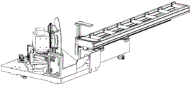
please see fig. 5 and 6, a double-end cutting saw with 45-degree angle for door and window frame section bar comprises a lathe bed 1, a left sawing machine head 4, a right sawing machine head 5, an electric control box and an operation console 2, wherein the left sawing machine head 4 is a fixed machine head, the right sawing machine head 5 is a movable machine head and can move left and right on the lathe bed 1, the electric control box is arranged at the left end (not shown in the figure) of the lathe bed 1, the operation console 2 is arranged at the front side of the lathe bed 1, and a first linear guide rail 3 and a rack 7 are horizontally arranged on the lathe bed 1 along the left and right directions.
Referring to fig. 7 to 11, the left sawing machine head 4 and the right sawing machine head 5 have basically the same structure, and each of the left sawing machine head and the right sawing machine head comprises a bottom plate 414, a horizontal workbench 44, a vertical workbench 47, a section bar clamping device, a sawing motor 416, a saw blade and a working mechanism, wherein the sawing motor 416 drives the saw blade to rotate, and the working mechanism drives the saw blade to work for cutting the section bar; the working mechanism can adopt modes of horizontal working, vertical working, swinging working and the like, and in the embodiment, the working mechanism adopts a swinging working mechanism; the lower bottom surface of the bottom plate 414 is provided with a sliding block 53 matched with the first linear guide rail 3, the front end of the upper bottom surface of the bottom plate 414 is provided with a square box bracket 410, the horizontal workbench 44 is arranged at the upper end of the square box bracket 410, and the vertical workbench 47 is arranged on the rear side surface of the square box bracket 410; the rear end of the bottom plate 414 is hinged with a machine head shield 415, which is of a known structure; the bottom plate 414 is provided with an adjusting plate 412, the adjusting plate 412 is provided with a sliding plate 413 in a sliding way, the swinging work feed mechanism is arranged on the sliding plate 413 and comprises a first hinge seat 418, a second hinge seat 423, a motor seat 417 with the lower end hinged on the first hinge seat 418 and a work feed cylinder 424 hinged on the second hinge seat 423, the sawing motor 416 is arranged at the upper end of the motor seat 417, the saw blade is directly connected to the output shaft of the sawing motor 416, and the axis of the sawing motor 416 is parallel to the horizontal workbench 44 so as to ensure that the saw blade is vertical to the horizontal workbench 44; the rod end of the working air inlet cylinder 424 is hinged with the upper end part of the motor seat 417; the vertical workbench 47 is provided with a saw notch 472, the power supply cylinder 424 drives the motor seat 417 to swing on the first hinge seat 418 to drive the sawing motor 416 and the saw blade to work in and out, and the saw blade stretches out of the saw notch 472 to cut the profile during work in.
By providing the adjustment plate 412 on the bottom plate 414, the saw blade angle can be adjusted when the saw blade angle is required to be corrected in the initial state of the adjustment device or after a period of use, so as to ensure that the angle between the saw blade and the vertical table 47 is fixed at 45 degrees. The bottom plate 414 is provided with a bolt hole, the adjusting plate 412 is provided with a through hole, the bolt passes through the through hole and is screwed into the screw hole to fix the adjusting plate 412 on the bottom plate 414, and the adjusting plate 412 is adjusted, positioned and fixed by matching with a known structure such as a positioning pin.
A saw blade material-letting mechanism is arranged between the adjusting plate 412 and the sliding plate 413, and comprises a material-letting driving mechanism, a material-letting return mechanism and a second linear guide rail pair 411, wherein the material-letting driving mechanism drives the sliding plate 413 to horizontally move away from the end surface of the cut section bar on the adjusting plate 412, and the material-letting return mechanism drives the sliding plate 413 to reversely move back to the original position; the guide rail of the second linear guide rail pair 411 is mounted on the adjusting plate 412, and the slider is mounted on the slide plate 413; the direction of movement of the second linear guide pair 411 is parallel to the axis of the sawing motor 416.
The material-letting driving mechanism specifically comprises a first hinge shaft 420, a second hinge shaft 422, a material-letting cylinder 421 and a cam 419 which are vertically arranged on the adjusting plate 412, wherein the tail end of the material-letting cylinder 421 is hinged on the second hinge shaft 422, one end of the cam 419 is hinged with the first hinge shaft 420, the other end of the cam 419 is hinged with the rod end of the material-letting cylinder 421, the side surface of the cam 419 is abutted against the side surface of the sliding plate 413, the material-letting cylinder 421 drives the cam 419 to rotate, and the cam 419 drives the sliding plate 413 to slide along the linear guide rail pair; please refer to fig. 11, the material return mechanism includes a first spring seat 425 fixed on the adjusting plate 412 and a second spring seat 426 correspondingly fixed on the sliding plate 413, and a compression spring 427 is disposed between the first spring seat 425 and the second spring seat 426.
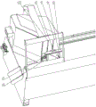
Referring to fig. 7 to 9 and fig. 12 to 14, the profile clamping device specifically includes a left horizontal pressing device 45 and a left vertical pressing device 49, which are disposed on the left sawing machine head 4, and a right horizontal pressing device 56 and a right vertical pressing device 57, which are disposed on the right sawing machine head 5;
the left horizontal pressing device 45 and the right horizontal pressing device 56 respectively comprise a horizontal pressing air cylinder 451 and a horizontal pressing plate 452, the horizontal pressing air cylinder 451 is arranged on the rear side surface of the vertical workbench 47, the rod end can extend forwards from through holes arranged on the vertical workbench 47 and the square box bracket 410 and is hinged with the lower end of the horizontal pressing plate 452, a first long hole 441 in the front-back direction is arranged on the horizontal workbench 44, the upper end of the horizontal pressing plate 452 extends upwards from the first long hole 441 to the table surface of the horizontal workbench 44, a first pressing block 456 is arranged at the end part of the horizontal pressing air cylinder 451, and the horizontal pressing air cylinder 451 drives the horizontal pressing plate 452 to slide in the first long hole 441;
in order to provide guiding for the horizontal pressing plate 452, the left horizontal pressing device 45 and the right horizontal pressing device 56 further comprise a third guide rail pair 457 which is parallel to the horizontal pressing cylinder 451, wherein a sliding block of the third guide rail pair 457 is connected to the rear side surface of the vertical working table 47 through a first L-shaped bracket 458, and the front end of the guide rail of the third guide rail pair 457 can extend forwards from through holes arranged on the vertical working table 47 and the square box bracket 410 and is connected with the lower end of the horizontal pressing plate 452;
The front side surface of the upper end of the horizontal pressure plate 452 is provided with a second pressure plate 453, and the upper end part of the second pressure plate 453 is provided with a second pressing block 455; the second pressure plate 453 is provided with a vertical long hole 4531, the position of the second pressing block 455 can be adjusted up and down, and a screw passes through the vertical long hole 4531 and is screwed into a bolt hole on the horizontal pressure plate 452 to fix the second pressure plate 453 on the horizontal pressure plate 452; the second pressing block 455 is connected to the front end of the screw 454, the rear end of the screw 454 is in threaded connection with a threaded hole at the upper end of the horizontal pressing plate 452, and the position of the second pressing block 455 can be adjusted forwards and backwards; the first pressing block 456 and the second pressing block 455 adopt wear-resistant rubber blocks with the hardness of 90 degrees;
the left vertical pressing device 49 and the right vertical pressing device 57 respectively comprise a vertical pressing cylinder 491 and a vertical pressing plate 492, the vertical pressing cylinder 491 is mounted on the rear side surface of the vertical workbench 47, the rod end is hinged with the rear end of the vertical pressing plate 492, a vertical second long hole 471 is formed in the vertical workbench 47, the front end of the vertical pressing plate 492 extends out of the table top of the vertical workbench 47 forwards from the second long hole 471, a third pressing block 494 is arranged at the end of the vertical pressing plate 492, and the vertical pressing cylinder 491 drives the vertical pressing plate 492 to slide in the second long hole 471.
In order to provide guiding for the vertical pressing plate 492, the left vertical pressing device 49 and the right vertical pressing device 57 further include a fourth rail pair 493 disposed parallel to the vertical pressing cylinder 491, the rail of the fourth rail pair 493 is connected to the rear side of the vertical table 47, and the slider of the fourth rail pair 493 is connected to the rear end of the vertical pressing plate 492 through a second L-shaped bracket 495.
The above is where the structures of the left and right sawing heads 4, 5 are substantially the same, and the differences between the left and right sawing heads 4, 5 are explained below.
Referring to fig. 7 to 8 and 18, a left blanking plate 41 inclined downward and leftward is disposed on the left side of the horizontal table 44 of the left sawing machine head 4, and a right blanking plate 54 inclined downward and rightward is disposed on the right side of the horizontal table 44 of the right sawing machine head 5; the left side of the horizontal workbench 44 of the left sawing machine head 4 is provided with a section bar end positioning device, the left sawing machine head comprises a positioning air cylinder 48 vertically arranged on a vertical workbench 47, the rod end of the positioning air cylinder 48 is connected with a positioning rod 42, a through hole is formed in the left blanking plate 41, and the positioning air cylinder 48 drives the positioning rod 42 to extend upwards from the through hole to position the end part of the section bar. The distance between the positioning rod 42 and the saw cut 472 is preferably set to ensure that the cut scrap stub bar is minimized. The positioning cylinder 48 in this embodiment is a three-axis cylinder.
Referring to fig. 15 to 17, in this embodiment, the lower bottom surfaces of the bottom plates 414 of the left sawing machine head 4 and the right sawing machine head 5 are respectively provided with a sliding block 53 matched with the first linear guide rail 3, that is, the left sawing machine head 4 and the right sawing machine head 5 can move left and right on the guide rails; except that the left sawing machine head 4 is not provided with a transverse moving driving mechanism, and the left sawing machine head can be manually forced to move on the guide rail for the convenience in manufacturing, installation and adjustment. As with the double-head dicing saw of the prior art, the left sawing head 4 of the present embodiment is provided as a fixed head, which is locked to the left end of the bed 1 by a fixing clamp 429; specifically, the cross section of fixation clamp 429 is the reverse U-shaped, and the U-shaped cross section looks adaptation of cross-section and first straight line guide rail 3, and the bottom of U-shaped upwards has opening logical groove 4291 down, and the upper portion of fixation clamp 429 is equipped with vertical screw hole 4292, connects fixation clamp 429 in the lower part of bottom plate 414 with the bolt, and the upper portion of fixation clamp 429 still is equipped with horizontal through hole 4293, is connected with the nut after the screw thread end of bolt passes horizontal through hole 4293, holds fixation clamp 429 on first straight line guide rail 3, and fixation clamp 429 sets up two, corresponds with two first straight line guide rails 3 respectively to it is fixed with left saw cut aircraft nose 4. The right sawing machine head 5 is a movable machine head, a bottom plate 414 of the right sawing machine head is provided with a transverse driving motor 51, and an output shaft of the transverse driving motor 51 is connected with a gear 52 meshed with the rack 7; in this embodiment, the transverse driving motor 51 adopts a servo motor to drive the right sawing machine head 5 to move left and right on the machine body 1 along the first linear guide rail 3, and the distance between the right sawing machine head and the left sawing machine head 4 is adjusted.
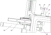
Please refer to fig. 5-6 and fig. 18-22, in this embodiment, the right end of the bottom plate 414 of the right sawing machine head 5 is further connected with a bracket 61, the bracket 61 is provided with an ultra-short material cutting mechanism 6, which includes a material carrying frame 63 and an auxiliary material pressing device disposed on the material carrying frame 63, a short material driving device and a fifth linear guide pair 62 are disposed between the material carrying frame 63 and the bracket 61, the short material driving device drives the material carrying frame 63 to move left and right on the bracket 61, the guide rail of the fifth linear guide pair 62 is mounted on the lower bottom surface of the material carrying frame, and the slide block is mounted on the upper bottom surface of the bracket 61.
The auxiliary pressing device comprises an auxiliary pressing cylinder 633 and an auxiliary pressing block 634, wherein the auxiliary pressing cylinder 633 is vertically arranged at the rear side of the material carrying frame 63, and the auxiliary pressing block 634 is connected with the rod end of the auxiliary pressing cylinder 633; the short material driving device is an air cylinder 64, the tail end of the air cylinder 64 is connected to the right end of the bracket 61, and the rod end of the air cylinder 64 is connected to the left end of the material carrying frame 63; the material carrying frame 63 is provided with a positioning plate 631, and the front side surface of the positioning plate 631 is coplanar with the front side surface of the vertical workbench 47; the material supporting frame 63 is rotatably provided with a material supporting roller 632, and the plane formed by the upper bus of the material supporting roller 632 is coplanar with the upper plane of the horizontal workbench 44. The lower part of the right end of the bracket 61 is provided with a supporting leg 611, the lower end of the supporting leg 611 is rotatably connected with a roller 612, and the roller 612 rolls along the first linear guide rail 3.
A material moving cylinder 65 is further arranged between the rod end of the cylinder 64 and the left end of the material carrying frame 63, the rod end of the material moving cylinder 65 is connected with the rod end of the cylinder 64, and the tail end of the material moving cylinder 65 is connected to the left end of the material carrying frame 63.
In this embodiment, an electrical control box is disposed at the left end of the lathe bed 1, an industrial personal computer is disposed in the electrical control box, an operation console 2 is disposed at the front side of the lathe bed 1, control buttons and a touch screen are disposed on the electrical control box, parameters such as the length of a section bar to be processed, the cutting angles of two ends, the height and the width of the section bar can be input, the cutting operation can be performed, and the processing process can be monitored in a display.
The sawing motor 416 and the transverse driving motor 51 are connected with a control system of the industrial personal computer; the working air inlet cylinder 424, the material feeding cylinder 421, the auxiliary material pressing cylinder 633, the cylinder 64 of the short material driving device, the material moving cylinder 65, the positioning cylinder 48, the horizontal pressing cylinder 451 and the vertical pressing cylinder 491 are connected with an air source through pipelines and electromagnetic valves, and the electromagnetic valves are connected with a control system;
in this embodiment, the control system uses the upper computer software+plc control system, which is not described in detail in the prior art.
In the invention, the transverse driving motor 51 drives the right sawing machine head 5 to move left and right on the machine body 1 along the first linear guide rail 3, so that the interval between the left sawing machine head 4 and the right sawing machine head 5 can be adjusted for cutting sectional materials with different lengths; before the profile is placed, the positioning cylinder 48 drives the positioning rod 42 to lift, so that the left end surface of the profile leans against the positioning rod 42 to position the length direction of the profile, and after the profile is cut, the positioning rod 42 descends, so that the waste material head smoothly slides down into the waste material groove; the horizontal compaction cylinder 451, the vertical compaction cylinder 491 and the auxiliary material pressing cylinder 633 respectively drive the pressing blocks connected with the horizontal compaction cylinder 451 and the vertical compaction cylinder 491 to compact or loosen the pressing blocks; when the ultra-short material is required to be cut, the cylinder 64 of the short material driving device drives the material carrying frame 63 to move rightwards, so that the distance between the left end face of the profile and the right saw blade 55 is shortened, and the ultra-short material can be processed. The sawing motor 416 drives the saw blade to rotate, and the working air inlet cylinder 424 drives the motor seat 417 to swing on the first hinge seat 418 to drive the sawing motor 416 and the saw blade to work in cutting the profile; after cutting is completed, the material moving cylinder 65 drives the material carrying frame 63 to move rightwards, the left end face of the blank section bar 43 is separated from the right saw blade 55 by a distance of 5mm, and then the left saw blade 46 and the right saw blade 55 are driven by the material letting cylinder 421 to move transversely by 1mm, so that saw teeth are separated from the end face of the section bar which is already cut, and the saw blade is prevented from returning to sweep materials. The actions are controlled by a control system of an industrial personal computer; the specific control programming process is designed according to the characteristics of the processed profile and the actual operation requirement, does not belong to the structural scope of the invention, and the circuit arrangement and connection for realizing control can be designed according to the hardware structure of the invention, and can be overcome by means of common knowledge in the electric control field in combination with action purposes, so that the invention is not described in detail.
Embodiment two:
the method for processing the door and window frame sash profile by using the double-head cutting saw with the 45-degree angle of the door and window frame sash profile in the embodiment comprises the following steps:
please refer to fig. 1 and 2, taking processing of door and window frame material section as an example, a finished section with length l=1450 mm shown in fig. 2 can be processed on a blank section 43 with length 6000mm, wherein 4 sections A1, A2, A3 and A4 are total:
s1, adjusting the distance between a right sawing machine head 5 and a left sawing machine head 4 according to the length dimension L of the finished section to be processed in the batch; the first pressing block 456 and the second pressing block 455 of the left vertical pressing device 49 and the right vertical pressing device 57 are adjusted to proper positions;
s2, feeding, namely manually placing the blank section bar 43 on a horizontal workbench 44, leaning a mounting surface of the section bar against a vertical workbench 47, bonding the outer side surface of the section bar on the horizontal workbench 44, and leaning the left end of the section bar against a positioning rod 42;
s3, clamping the section bar, wherein the left horizontal pressing device 45, the right horizontal pressing device 56, the left vertical pressing device 49, the right vertical pressing device 57 and the auxiliary pressing device sequentially act to press the section bar on the horizontal workbench 44, the vertical workbench 47 and the material carrying frame 63; the handpiece shield 415 is lowered;
s4, starting an industrial air inlet cylinder 424, extending the rod end of the industrial air inlet cylinder 424, and driving the left saw blade 46 and the right saw blade 55 to swing and saw the section bar;
S5, starting a material moving cylinder 65, retracting a rod end of the material moving cylinder 65, and driving a material carrying frame 63 and blank profiles 43 on the material carrying frame to move rightwards; simultaneously, the positioning cylinder 48 drives the positioning rod 42 to descend, and the waste heads fall down;
s6, starting a material letting cylinder 421, enabling a piston rod of the material letting cylinder 421 to extend out of a driving cam 419 to rotate, and enabling the cam 419 to push a sliding plate 413 and drive a saw blade motor and a saw blade to move transversely so as to separate from the end face of the cut section;
s7, retracting the rod end of the working air inlet cylinder 424 to drive the left saw blade 46 and the right saw blade 55 to return along the cutting track; the handpiece shield 415 is raised;
s8, enabling a piston rod of the material cylinder 421 to retract to drive the cam 419 to rotate reversely, and enabling the spring to push the sliding plate 413 and drive the saw blade motor and the saw blade to return;
s9, clamping and loosening, namely loosening the clamping of the section bar by the left horizontal pressing device 45, the right horizontal pressing device 56, the left vertical pressing device 49, the right vertical pressing device 57 and the auxiliary pressing device;
s10, manually taking out the processed section A1;
s11, repeating the steps S2 to S10, and processing sections A2 to A4;
s12, repeating the steps S2-S11, and processing the next section.
Embodiment III:
the method for processing the ultra-short door and window frame sash profile by using the double-head cutting saw with the 45-degree angle of the door and window frame sash profile in the first embodiment comprises the following steps:
Please refer to fig. 1 and 2, taking processing of door and window frame material section as an example, a finished section with length l=200mm shown in fig. 2 can be processed on a blank section 43 with length 6000mm, wherein 29 sections of A1, A2 and … … a30 are formed on the blank section 43:
s1, adjusting the distance between a right sawing machine head 5 and a left sawing machine head 4 to be 500mm according to the length dimension L=200 mm of the finished section to be processed in the batch and the stroke of a cylinder 64 to be L0=400 mm; the first pressing block 456 and the second pressing block 455 of the left vertical pressing device 49 and the right vertical pressing device 57 are adjusted to proper positions;
s2, feeding, namely manually placing the blank section bar 43 on a horizontal workbench 44, leaning a mounting surface of the section bar against a vertical workbench 47, bonding the outer side surface of the section bar on the horizontal workbench 44, and leaning the left end of the section bar against a positioning rod 42;
s3, clamping the section bar, wherein the left horizontal pressing device 45, the right horizontal pressing device 56, the left vertical pressing device 49, the right vertical pressing device 57 and the auxiliary pressing device sequentially act to press the section bar on the horizontal workbench 44, the vertical workbench 47 and the material carrying frame 63; the handpiece shield 415 is lowered;
s4, starting an industrial air inlet cylinder 424 of the left sawing machine head 4, extending out a rod end of the industrial air inlet cylinder 424, and driving the left saw blade 46 to swing to saw the section bar;
S5, clamping and loosening, namely loosening the clamping of the section bar by a left horizontal pressing device 45, a right horizontal pressing device 56, a left vertical pressing device 49 and a right vertical pressing device 57;
s6, starting an air cylinder 64 of the short material driving device, retracting a rod end of the air cylinder 64, and driving a material carrying frame 63 and blank profiles 43 on the material carrying frame to move rightwards by 400mm; simultaneously, the positioning cylinder 48 drives the positioning rod 42 to descend, and the waste heads fall down;
s7, clamping the section bar, and sequentially acting a right horizontal pressing device 56 and a right vertical pressing device 57 to press the section bar on the horizontal workbench 44 and the vertical workbench 47;
s8, starting an industrial air inlet cylinder 424 of the right sawing machine head 5, extending out a rod end of the industrial air inlet cylinder 424, and driving a right saw blade 55 to swing to saw the section bar;
s9, starting a material moving cylinder 65, retracting a rod end of the material moving cylinder 65, and driving a material carrying frame 63 and blank profiles 43 on the material carrying frame to move rightwards;
s10, starting a material letting cylinder 421, enabling a piston rod of the material letting cylinder 421 to extend out of a driving cam 419 to rotate, and enabling the cam 419 to push a sliding plate 413 and drive a saw blade motor and a saw blade to move transversely so as to separate from the end face of a cut section;
s11, retracting the rod end of the working air inlet cylinder 424 to drive the left saw blade 46 and the right saw blade 55 to return along the cutting track; the handpiece shield 415 is raised;
S12, a piston rod of the material cylinder 421 is retracted to drive the cam 419 to rotate reversely, and the spring pushes the sliding plate 413 and drives the saw blade motor and the saw blade to return;
s13, clamping and loosening, wherein the right horizontal pressing device 56, the right vertical pressing device 57 and the auxiliary pressing device loosen the clamping of the profile;
s14, manually taking out the processed section A1;
s15, repeating the steps S2 to S14, and processing sections A2 to A29;
s16, repeating the steps S2-S15, and processing the next section.
In describing the present invention, it should be noted that the directions or positional relationships indicated by the terms "left", "right", "front", "rear", "upper", "lower", "inner", "outer", etc. are based on the directions or positional relationships shown in the drawings, are merely for convenience of describing the present invention and simplifying the description, and do not indicate or imply that the devices or elements referred to must have a specific orientation, be constructed and operated in a specific orientation, and thus should not be construed as limiting the present invention.
Unless specifically stated or limited otherwise, the terms "mounted," "connected," and "coupled" are to be construed broadly, and may be, for example, fixedly connected, detachably connected, or integrally connected; the two components can be connected mechanically or electrically, can be connected directly or indirectly through an intermediate medium, and can be communicated inside the two components. The specific meaning of the above terms in the present invention will be understood in specific cases by those of ordinary skill in the art.
Other than the technical features described in the specification, all are known to those skilled in the art.
The above-mentioned embodiments are only for understanding the present invention, and are not intended to limit the technical solutions described in the present invention, and a person skilled in the relevant art may make various changes or modifications based on the technical solutions described in the claims, and all equivalent changes or modifications are intended to be included in the scope of the claims of the present invention.
Claims (10)
1. A sawing method of a double-head cutting saw for door and window frame section bars with an angle of 45 degrees is characterized in that: the method adopts a double-head cutting saw with 45-degree angle for sawing the door and window frame sash section bar, and comprises the following specific steps:
s1: manually placing the blank profile on a horizontal workbench, leaning the mounting surface of the profile against a vertical workbench, and fitting the outer side surface of the profile on the horizontal workbench;
s2, clamping the profile by a profile clamping device;
the double-head cutting saw for the door and window frame fan section bar with the angle of 45 degrees comprises a lathe bed, wherein a left sawing machine head and a right sawing machine head are arranged on the lathe bed, and the right sawing machine head is arranged on the lathe bed in a sliding manner; the left sawing machine head and the right sawing machine head comprise a horizontal workbench, a vertical workbench, a section bar clamping device, a sawing motor, a saw blade and a working mechanism, wherein the sawing motor drives the saw blade to rotate, and the saw blade is vertical to the horizontal workbench and forms an included angle of 45 degrees with the vertical workbench; the right sawing machine head is provided with a saw blade material-letting mechanism; a material carrying frame capable of moving left and right is arranged on the right sawing machine head;
S3, driving a saw blade to cut the profile by the aid of a working mechanism;
s4, moving the material carrying frame and blank sectional materials on the material carrying frame rightwards;
s5, the saw blade letting mechanism drives the saw blade motor and the saw blade to move transversely and separate from the end face of the cut section;
s6, the working mechanism drives the left saw blade and the right saw blade to return along a cutting track;
s7, loosening the clamping of the section bar by the section bar clamping device;
s8, manually taking out a section of finished section bar after processing;
and S9, repeating the steps S2 to S8, and processing the next section of section.
2. The sawing method of a double-head dicing saw for door and window frame and sash profile 45 degrees according to claim 1, characterized in that: the left sawing machine head and the right sawing machine head also comprise a bottom plate which can slide on the machine body, the horizontal workbench and the vertical workbench are arranged at the front end of the bottom plate, and the rear end of the bottom plate is hinged with a machine head shield; the bottom plate is provided with an adjusting plate, a sliding plate is arranged on the adjusting plate in a sliding manner, a first hinge seat and a second hinge seat are arranged on the sliding plate, the lower end of the motor seat is hinged to the first hinge seat, the sawing motor is arranged at the upper end of the motor seat, and the saw blade is connected to an output shaft of the sawing motor; the working air inlet cylinder is hinged to the second hinge seat, and the rod end of the air cylinder is hinged to the upper end part of the motor seat; the working air inlet cylinder drives the motor seat to swing on the first hinge seat to drive the sawing motor and the saw blade to work in cutting the profile; the saw blade letting material mechanism is arranged between the adjusting plate and the sliding plate.
3. The sawing method of a double-head dicing saw for door and window frame and sash profile 45 degrees according to claim 2, characterized in that: the saw blade material letting mechanism comprises a material letting driving mechanism, a material letting return mechanism and a second linear guide rail pair, wherein the material letting driving mechanism drives a sliding plate to horizontally move away from the end surface of the cut section bar on the adjusting plate, and the material letting return mechanism drives the sliding plate to reversely move back to the original position; the guide rail of the second linear guide rail pair is arranged on the adjusting plate, and the sliding block is arranged on the sliding plate; the moving direction of the second linear guide rail pair is parallel to the axis of the sawing motor.
4. A sawing method of a double-head dicing saw for door and window frame and sash profile 45 degrees according to claim 3, characterized in that: the material-letting driving mechanism comprises a first hinge shaft, a second hinge shaft, a material-letting cylinder and a cam, wherein the first hinge shaft and the second hinge shaft are vertically arranged on the adjusting plate, the tail end of the material-letting cylinder is hinged on the second hinge shaft, one end of the cam is hinged with the first hinge shaft, the other end of the cam is hinged with the rod end of the material-letting cylinder, the side surface of the cam is abutted against the side surface of the sliding plate, the material-letting cylinder drives the cam to rotate, and the cam drives the sliding plate to slide along the linear guide rail pair; the material return mechanism comprises a first spring seat fixed on the adjusting plate and a second spring seat correspondingly fixed on the sliding plate, and a compression spring is arranged between the first spring seat and the second spring seat.
5. The sawing method of a double-head dicing saw for door and window frame and sash profile 45 degrees according to claim 2, characterized in that: the right sawing machine head comprises a right sawing machine head bottom plate, and is characterized in that the right end of the right sawing machine head bottom plate is connected with a bracket, an ultra-short material cutting mechanism is arranged on the bracket, the ultra-short material cutting mechanism comprises a material carrying frame and an auxiliary material pressing device arranged on the material carrying frame, a short material driving device and a fifth linear guide rail pair are arranged between the material carrying frame and the bracket, the short material driving device drives the material carrying frame to move left and right on the bracket, a guide rail of the fifth linear guide rail pair is arranged on the lower bottom surface of the material carrying frame, and a sliding block is arranged on the upper bottom surface of the bracket.
6. The sawing method of a double-head cutting saw for door and window frame sash profile 45 degrees according to claim 5, wherein: the auxiliary pressing device comprises an auxiliary pressing cylinder and an auxiliary pressing block, wherein the auxiliary pressing cylinder is vertically arranged at the rear side of the material carrying frame, and the auxiliary pressing block is connected to the rod end of the auxiliary pressing cylinder; the short material driving device is an air cylinder, the tail end of the air cylinder is connected to the right end of the bracket, and the rod end of the air cylinder is connected to the left end of the material carrying frame; the material carrying frame is provided with a positioning plate, and the front side surface of the positioning plate is coplanar with the front side surface of the vertical workbench; the material supporting frame is rotatably provided with a material supporting roller, and the plane formed by the upper bus of the material supporting roller is coplanar with the upper plane of the horizontal workbench.
7. The sawing method of a double-head dicing saw for door and window frame and sash profile 45 degrees according to claim 6, characterized in that: a material moving cylinder is further arranged between the rod end of the cylinder and the left end of the material carrying frame, the rod end of the material moving cylinder is connected with the rod end of the cylinder, and the tail end of the material moving cylinder is connected to the left end of the material carrying frame.
8. The sawing method of a double-head dicing saw for door and window frame and sash profile 45 degrees according to claim 2, characterized in that: the left side of the left sawing machine head horizontal workbench is provided with a left blanking plate which is inclined leftwards and downwards, and the right side of the right sawing machine head horizontal workbench is provided with a right blanking plate which is inclined rightwards and downwards; the left side of left saw cuts aircraft nose horizontal workbench is provided with section bar tip positioner, including vertical location cylinder of installing on vertical workstation, the rod end of location cylinder is connected with the locating lever, left blanking plate on be equipped with the through-hole, location cylinder drive locating lever can upwards stretch out from the through-hole and fix a position the tip of section bar.
9. Sawing method of a double-head dicing saw for door and window frame and sash profile 45 degree angle according to any one of claims 1 to 8, characterized in that: the section bar clamping device comprises a left horizontal pressing device and a left vertical pressing device which are arranged on a left sawing machine head, and a right horizontal pressing device and a right vertical pressing device which are arranged on a right sawing machine head;
The left horizontal pressing device and the right horizontal pressing device both comprise a horizontal pressing cylinder and a horizontal pressing plate, the horizontal pressing cylinder is arranged on the rear side surface of the vertical workbench, the rod end can extend forwards from a through hole arranged on the vertical workbench and is hinged with the lower end of the horizontal pressing plate, a first long hole in the front-back direction is formed in the horizontal workbench, the upper end of the horizontal pressing plate extends upwards from the first long hole to the table top of the horizontal workbench, a first pressing block is arranged at the end part of the horizontal pressing cylinder, and the horizontal pressing cylinder drives the horizontal pressing plate to slide in the first long hole;
the left vertical pressing device and the right vertical pressing device comprise a vertical pressing cylinder and a vertical pressing plate, the vertical pressing cylinder is mounted on the rear side face of the vertical workbench, the rod end is hinged to the rear end of the vertical pressing plate, a vertical second long hole is formed in the vertical workbench, the front end of the vertical pressing plate extends out of the table top of the vertical workbench forwards from the second long hole, a third pressing block is arranged at the end of the vertical pressing plate, and the vertical pressing cylinder drives the vertical pressing plate to slide in the second long hole.
10. The sawing method of a double-head dicing saw for door and window frame and sash profile 45 degrees according to claim 9, characterized in that: the left horizontal pressing device and the right horizontal pressing device also comprise a third guide rail pair which is arranged in parallel with the horizontal pressing cylinder, a sliding block of the third guide rail pair is connected to the rear side surface of the vertical workbench, and the front end of a guide rail of the third guide rail pair can extend forwards from a through hole arranged on the vertical workbench and is connected with the lower end of the horizontal pressing plate;
The front side surface of the upper end of the horizontal pressing plate is provided with a second pressing plate, and the upper end part of the second pressing plate is provided with a second pressing block; the second pressing plate is provided with a vertical long hole, the position of the second pressing block can be adjusted up and down, and a screw penetrates through the vertical long hole to fix the second pressing plate on the horizontal pressing plate; the second pressing block is connected to the front end of the screw rod, the rear end of the screw rod is in threaded connection with a threaded hole at the upper end of the horizontal pressing plate, and the position of the second pressing block can be adjusted forwards and backwards;
the left vertical pressing device and the right vertical pressing device also comprise a fourth guide rail pair which is arranged in parallel with the vertical pressing cylinder, the guide rail of the fourth guide rail pair is connected to the rear side surface of the vertical workbench, and the sliding block of the fourth guide rail pair is connected with the rear end of the vertical pressing plate.
Priority Applications (1)
| Application Number | Priority Date | Filing Date | Title |
|---|---|---|---|
| CN202211704512.7A CN116275278A (en) | 2022-12-29 | 2022-12-29 | Sawing method of double-head cutting saw with 45-degree angle for door and window frame section bar |
Applications Claiming Priority (1)
| Application Number | Priority Date | Filing Date | Title |
|---|---|---|---|
| CN202211704512.7A CN116275278A (en) | 2022-12-29 | 2022-12-29 | Sawing method of double-head cutting saw with 45-degree angle for door and window frame section bar |
Publications (1)
| Publication Number | Publication Date |
|---|---|
| CN116275278A true CN116275278A (en) | 2023-06-23 |
Family
ID=86787596
Family Applications (1)
| Application Number | Title | Priority Date | Filing Date |
|---|---|---|---|
| CN202211704512.7A Pending CN116275278A (en) | 2022-12-29 | 2022-12-29 | Sawing method of double-head cutting saw with 45-degree angle for door and window frame section bar |
Country Status (1)
| Country | Link |
|---|---|
| CN (1) | CN116275278A (en) |
Cited By (1)
| Publication number | Priority date | Publication date | Assignee | Title |
|---|---|---|---|---|
| CN116571810A (en) * | 2023-07-14 | 2023-08-11 | 山东辰禾智能装备有限公司 | Sawing device and method for profile with drainage slope |
-
2022
- 2022-12-29 CN CN202211704512.7A patent/CN116275278A/en active Pending
Cited By (2)
| Publication number | Priority date | Publication date | Assignee | Title |
|---|---|---|---|---|
| CN116571810A (en) * | 2023-07-14 | 2023-08-11 | 山东辰禾智能装备有限公司 | Sawing device and method for profile with drainage slope |
| CN116571810B (en) * | 2023-07-14 | 2023-11-03 | 山东辰禾智能装备有限公司 | Sawing device and method for profile with drainage slope |
Similar Documents
| Publication | Publication Date | Title |
|---|---|---|
| CN108188756B (en) | Glass window section bar preprocessing system | |
| CN112621230A (en) | Profile sawing, milling and drilling integrated machine | |
| CN211889827U (en) | Center pillar angle sign indicating number duplex position drilling tapping cutting all-in-one | |
| CN210967185U (en) | Double housing keyway planer | |
| CN116275278A (en) | Sawing method of double-head cutting saw with 45-degree angle for door and window frame section bar | |
| CN113305577A (en) | Numerical control section end face milling center | |
| CN111660104A (en) | Saw cut end milling machine | |
| CN218964231U (en) | 45-degree double-head cutting saw for door and window frame section bar | |
| CN114734273B (en) | High-precision numerical control cutting equipment based on sensor | |
| CN109834772B (en) | Numerical control sawing and milling machine | |
| CN112705946A (en) | A all-in-one for section bar processing | |
| CN211250340U (en) | Conveying device in double-end sawing machine | |
| CN219074545U (en) | Saw blade letting mechanism of 45-degree double-head cutting saw for door and window frame section bar | |
| CN219093845U (en) | Section bar clamping device of 45-degree angle double-head cutting saw for door and window frame section bar | |
| CN220462442U (en) | 45-degree special cutting saw for aluminum-plastic section bar | |
| CN218964656U (en) | Laser saw cutting device | |
| CN220127678U (en) | Double-end double-head efficient numerical control end face milling machine | |
| CN217393830U (en) | Numerical control end surface milling machine for processing door and window section bar | |
| CN210633033U (en) | Automatic sawing equipment for 45-degree angle of aluminum profile | |
| CN220050266U (en) | Precise cutting saw convenient to feed | |
| CN218638700U (en) | Section bar precision saw cuts with righting clamping device | |
| CN219336381U (en) | Laser scribing device for sawing wire | |
| CN219211678U (en) | Drilling device | |
| CN220093735U (en) | Drilling, milling and sawing composite machining center for door and window profile | |
| CN209718012U (en) | A kind of five dish saw |
Legal Events
| Date | Code | Title | Description |
|---|---|---|---|
| PB01 | Publication | ||
| PB01 | Publication | ||
| SE01 | Entry into force of request for substantive examination | ||
| SE01 | Entry into force of request for substantive examination |