CN116236747A - Intelligent treadmill with adjustable angle - Google Patents
Intelligent treadmill with adjustable angle Download PDFInfo
- Publication number
- CN116236747A CN116236747A CN202310220704.9A CN202310220704A CN116236747A CN 116236747 A CN116236747 A CN 116236747A CN 202310220704 A CN202310220704 A CN 202310220704A CN 116236747 A CN116236747 A CN 116236747A
- Authority
- CN
- China
- Prior art keywords
- assembly
- frame
- driving
- running
- limit
- Prior art date
- Legal status (The legal status is an assumption and is not a legal conclusion. Google has not performed a legal analysis and makes no representation as to the accuracy of the status listed.)
- Pending
Links
Images


Classifications
-
- A—HUMAN NECESSITIES
- A63—SPORTS; GAMES; AMUSEMENTS
- A63B—APPARATUS FOR PHYSICAL TRAINING, GYMNASTICS, SWIMMING, CLIMBING, OR FENCING; BALL GAMES; TRAINING EQUIPMENT
- A63B22/00—Exercising apparatus specially adapted for conditioning the cardio-vascular system, for training agility or co-ordination of movements
- A63B22/02—Exercising apparatus specially adapted for conditioning the cardio-vascular system, for training agility or co-ordination of movements with movable endless bands, e.g. treadmills
- A63B22/0235—Exercising apparatus specially adapted for conditioning the cardio-vascular system, for training agility or co-ordination of movements with movable endless bands, e.g. treadmills driven by a motor
-
- A—HUMAN NECESSITIES
- A63—SPORTS; GAMES; AMUSEMENTS
- A63B—APPARATUS FOR PHYSICAL TRAINING, GYMNASTICS, SWIMMING, CLIMBING, OR FENCING; BALL GAMES; TRAINING EQUIPMENT
- A63B24/00—Electric or electronic controls for exercising apparatus of preceding groups; Controlling or monitoring of exercises, sportive games, training or athletic performances
- A63B24/0087—Electric or electronic controls for exercising apparatus of groups A63B21/00 - A63B23/00, e.g. controlling load
Landscapes
- Health & Medical Sciences (AREA)
- General Health & Medical Sciences (AREA)
- Physical Education & Sports Medicine (AREA)
- Cardiology (AREA)
- Vascular Medicine (AREA)
- Rehabilitation Tools (AREA)
Abstract
The invention discloses an intelligent treadmill with an adjustable angle, which belongs to the technical field of treadlemill, and comprises a first frame: the intelligent control terminal is fixedly connected to the top of the first rack, and holding rods are symmetrically arranged at the upper ends of the side walls of the first rack; the running assembly is arranged in the first frame and comprises a driving assembly and an anti-deviation running assembly, the driving assembly is connected with the first frame and is far away from the holding rod, and the anti-deviation running assembly is in driving connection; the inner wall of the first frame is connected with an angle adjusting assembly, the angle adjusting assembly comprises an adjusting assembly and an auxiliary guiding assembly, the driving assembly and the auxiliary guiding assembly are both connected with the first frame, and the driving assembly and the auxiliary guiding assembly are connected with an anti-deviation running assembly; through the mode, the adjustable angle type automobile seat can realize angle adjustment, and can meet the use requirements of most people.
Description
Technical Field
The invention relates to the technical field of treadmills, in particular to an intelligent treadlemill with an adjustable angle.
Background
The running machine can exercise muscles of the whole body of a human body, and is a common body-building device. The conventional running machine drives a running belt through a motor to enable a user to run or walk passively with different resistances.
The existing running machine is directly sleeved on the conveying roller, the conveying belt is lengthened after being used for a long time, the conveying belt is offset after being lengthened, the conveying belt which is offset to rotate can influence the force transmission direction, unsafe factors during running are increased, and meanwhile, the angle of the running machine is not adjustable, so that the use requirements of most people cannot be met.
Based on the above, the invention designs an intelligent running machine with adjustable angle to solve the above problems.
Disclosure of Invention
In view of the above-mentioned shortcomings of the prior art, the present invention provides an intelligent treadmill with adjustable angle.
In order to achieve the above purpose, the invention is realized by the following technical scheme:
an intelligent treadmill with adjustable angle includes a first frame:
the intelligent control terminal is fixedly connected to the top of the first rack, and holding rods are symmetrically arranged at the upper ends of the side walls of the first rack;
the running assembly comprises a driving assembly and an anti-deviation running assembly, wherein the driving assembly is connected with the first frame and is far away from the holding rod, and the anti-deviation running assembly is in driving connection;
the angle adjusting assembly comprises an adjusting assembly and an auxiliary guiding assembly, wherein the driving assembly and the auxiliary guiding assembly are both connected with the first frame, and the driving assembly and the auxiliary guiding assembly are connected with the deviation-preventing running assembly.
Still further, drive assembly includes first ring gear, support frame, first driving motor and second ring gear, support frame and first frame inner wall fixed connection, support frame top fixedly connected with first driving motor, first driving motor drive end is connected with the second ring gear, the meshing of second ring gear is connected with first ring gear.
Still further, prevent off-spot subassembly of running includes second frame, conveyer belt, backing plate, spacing, live-rollers and spacing spout, equal fixedly connected with second frame of backing plate front and back end, the end is rotated with the live-rollers through the bearing about the second frame and is connected, live-rollers front and back end fixedly connected with spacing spout, the live-rollers outer wall rotates and is connected with the conveyer belt, conveyer belt inner wall fixedly connected with and spacing spout cooperation use spacing, and backing plate top and the laminating sliding connection of conveyer belt upper half bottom surface.
Further, the first gear ring is fixedly arranged at the end part of the rotating roller on the right side.
Still further, adjusting part includes threaded rod, second driving motor, spacing guide rail, mount pad, first bevel gear, second bevel gear, spacing slider, cross axle and connecting plate, mount pad fixed mounting is on first frame inside wall, and the second driving motor is installed to the mount pad, and first bevel gear of second driving motor drive end fixedly connected with, first bevel gear meshing are connected with the second bevel gear, installs the threaded rod in the mounting hole of second bevel gear, and threaded rod threaded connection has spacing slider, and spacing slider passes through spacing sliding tray and spacing guide rail spacing sliding connection, and equal fixedly connected with cross axle around the spacing slider, the cross axle outer end rivets with connecting plate one end, and the connecting plate other end rivets with second frame inner wall.
Further, the limit guide rail is fixedly arranged at the inner bottom of the first frame.
Furthermore, the inner side wall of the first frame is rotationally connected with the threaded rod through a bearing.
Advantageous effects
According to the invention, the first bevel gear is driven to rotate by the second driving motor of the adjusting assembly of the angle adjusting assembly, the first bevel gear drives the second bevel gear to rotate, the second bevel gear drives the threaded rod to rotate, the threaded rod drives the limit sliding block to move along the limit guide rail, the limit sliding block drives the transverse shaft to move, the transverse shaft drives the connecting plate to rotate, the connecting plate drives the second rack to rotate along the circle center of the rotating roller on the right side, the second rack drives the conveyor belt to rotate along the circle center of the rotating roller on the right side, the inclination adjustment of the conveyor belt is realized, and meanwhile, the arc-shaped groove and the sliding column of the auxiliary guiding assembly cooperate to rotate and guide the second rack, so that the angle can be adjusted, and the use requirements of a plurality of people can be met.
The first driving motor of the driving assembly of the running assembly drives the second gear ring to rotate, the second gear ring drives the first gear ring to rotate, the first gear ring drives the rotating roller on the right side of the anti-deflection running assembly to rotate, the conveyor belt is driven to rotate under the cooperation of the rotating roller on the left side, the conveyor belt can run on the conveyor belt after rotating, meanwhile, the conveyor belt is limited under the cooperation of the limiting strips and the limiting sliding grooves, the conveyor belt can be prevented from being separated from the rotating roller, the rotation stability of the rotating roller is ensured, the deflection rotation phenomenon is avoided, the force transmission direction of the conveyor belt is ensured, unsafe factors during running are reduced, meanwhile, the supporting frame, the first driving motor and the second gear ring of the driving assembly are not contacted with the anti-deflection running assembly, and the adjusting force only needs to drive the anti-deflection running assembly and the first gear ring during the angle adjustment of the anti-deflection running assembly, so that the angle adjustment pressure of the anti-deflection running assembly is reduced, and the light weight angle adjustment of the anti-deflection running assembly is facilitated.
Drawings
In order to more clearly illustrate the embodiments of the present invention or the technical solutions in the prior art, the drawings used in the description of the embodiments or the prior art will be briefly described below. It is evident that the drawings in the following description are only some embodiments of the present invention and that other drawings may be obtained from these drawings without inventive effort for a person of ordinary skill in the art.
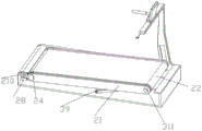
FIG. 1 is a perspective view of a main body structure of an intelligent running machine with adjustable angle;
FIG. 2 is a front view of an intelligent treadmill with adjustable angle according to the present invention;
FIG. 3 is a left side view of an angle adjustable intelligent treadmill architecture of the present invention;
FIG. 4 is a perspective view of a main body of an intelligent running machine with adjustable angle according to the present invention;
FIG. 5 is a cross-sectional view taken along the direction A-A of FIG. 2;
FIG. 6 is a cross-sectional view taken along the B-B direction of FIG. 3;
fig. 7 is a sectional view taken along the direction C-C of fig. 3.
Reference numerals in the drawings represent respectively:
1. first frame 2, running assembly 21, second frame 22, conveyor belt 23, backing plate 24, first gear ring 25, stop bar 26, rotating roller 27, stop chute 28, support frame 29, first drive motor 210, second gear ring 3, angle adjustment assembly 31, arcuate slot 32, threaded rod 33, second drive motor 34, stop rail 35, mount 36, first bevel gear 37, second bevel gear 38, stop slide 39, cross shaft 310, connecting plate 311, sliding post 4, intelligent control terminal 5, and grip.
Description of the embodiments
In order to make the objects, technical solutions and advantages of the embodiments of the present invention more clear, the technical solutions of the embodiments of the present invention will be clearly and completely described below with reference to the accompanying drawings in the embodiments of the present invention. It will be apparent that the described embodiments are some, but not all, embodiments of the invention. All other embodiments, which can be made by those skilled in the art based on the embodiments of the invention without making any inventive effort, are intended to be within the scope of the invention.
The invention is further described below with reference to examples.
Examples
Referring to fig. 1-7 of the drawings, an intelligent running machine with adjustable angle comprises a first frame 1:
the top of the first rack 1 is fixedly connected with an intelligent control terminal 4, and holding rods 5 are symmetrically arranged at the upper ends of the side walls of the first rack 1;
the running assembly 2 is arranged in the first frame 1, the running assembly 2 comprises a driving assembly and an anti-deviation running assembly, the driving assembly is connected with the first frame 1 and is far away from the holding rod 5, and the anti-deviation running assembly is in driving connection;
the driving assembly comprises a first gear ring 24, a supporting frame 28, a first driving motor 29 and a second gear ring 210, wherein the supporting frame 28 is fixedly connected with the inner wall of the first rack 1, the first driving motor 29 is fixedly connected to the top of the supporting frame 28, the second gear ring 210 is connected to the driving end of the first driving motor 29, and the first gear ring 24 is connected to the second gear ring 210 in a meshed manner;
the anti-deviation running assembly comprises a second frame 21, a conveyor belt 22, a base plate 23, a limit bar 25, a rotating roller 26 and a limit chute 27, wherein the front end and the rear end of the base plate 23 are fixedly connected with the second frame 21, the left end and the right end of the second frame 21 are rotationally connected with the rotating roller 26 through bearings, the front end and the rear end of the rotating roller 26 are fixedly connected with the limit chute 27, the outer wall of the rotating roller 26 is rotationally connected with the conveyor belt 22, the inner wall of the conveyor belt 22 is fixedly connected with the limit bar 25 matched with the limit chute 27, and the top of the base plate 23 is in fit sliding connection with the bottom surface of the upper half of the conveyor belt 22;
the first ring gear 24 is fixedly mounted to the end of the right-hand rotating roller 26;
the first driving motor 29 of the driving assembly of the running assembly 2 drives the second gear ring 210 to rotate, the second gear ring 210 drives the first gear ring 24 to rotate, the first gear ring 24 drives the right rotating roller 26 of the anti-deviation running assembly to rotate, the left rotating roller 26 is matched with the first gear ring 24 to drive the conveying belt 22 to rotate, the conveying belt 22 can run on the conveying belt 22 after rotating, meanwhile, the limiting strip 25 and the limiting chute 27 are matched with the limiting belt 22 to limit the conveying belt 22, the conveying belt 22 can be prevented from being separated from the rotating roller 26, the rotating stability of the rotating roller 26 is ensured, the phenomenon of deviation rotation is avoided, the force transmission direction of the conveying belt is ensured, unsafe factors during running are reduced, meanwhile, the supporting frame 28, the first driving motor 29 and the second gear ring 210 of the driving assembly are not contacted with the anti-deviation running assembly, and the adjusting force only needs to drive the anti-deviation running assembly and the first gear ring 24 during the angle adjustment of the anti-deviation running assembly, so that the angle adjustment pressure of the anti-deviation running assembly is reduced, and the light angle adjustment of the anti-deviation running assembly is facilitated;
the inner wall of the first frame 1 is connected with an angle adjusting component 3, the angle adjusting component 3 comprises an adjusting component and an auxiliary guiding component, the driving component and the auxiliary guiding component are both connected with the first frame 1, and the driving component and the auxiliary guiding component are connected with an anti-deviation running component;
the intelligent control terminal 4 is electrically connected with the running assembly 2 and the angle adjusting assembly 3, so that intelligent control is realized.
The adjusting assembly comprises a threaded rod 32, a second driving motor 33, a limit guide rail 34, a mounting seat 35, a first bevel gear 36, a second bevel gear 37, a limit sliding block 38, a transverse shaft 39 and a connecting plate 310, wherein the mounting seat 35 is fixedly arranged on the inner side wall of the first frame 1, the mounting seat 35 is provided with the second driving motor 33, the driving end of the second driving motor 33 is fixedly connected with the first bevel gear 36, the first bevel gear 36 is in meshed connection with the second bevel gear 37, the threaded rod 32 is arranged in a mounting hole of the second bevel gear 37, the threaded rod 32 is in threaded connection with the limit sliding block 38, the limit sliding block 38 is in limit sliding connection with the limit guide rail 34 through a limit sliding groove, the transverse shaft 39 is fixedly connected with the front and the rear of the limit sliding block 38, the outer end of the transverse shaft 39 is riveted with one end of the connecting plate 310, and the other end of the connecting plate 310 is riveted with the inner wall of the second frame 21;
the limit guide rail 34 is fixedly arranged at the inner bottom of the first frame 1;
the inner side wall of the first frame 1 is rotationally connected with the threaded rod 32 through a bearing;
the auxiliary guide assembly comprises an arc-shaped groove 31 and a sliding column 311, the inner wall of the first frame 1 is provided with the arc-shaped groove 31, the arc-shaped groove 31 is internally stuck and connected with the sliding column 311 in a sliding manner, and the inner end of the sliding column 311 is fixedly connected with the outer wall of the second frame 21;
the circle center of the sliding column 311 coincides with the circle center of the right rotating roller 26;
the first driving motor 29 of the driving assembly of the running assembly 2 drives the second gear ring 210 to rotate, the second gear ring 210 drives the first gear ring 24 to rotate, the first gear ring 24 drives the rotating roller 26 on the right side of the anti-deviation running assembly to rotate, the belt 22 is driven to rotate under the cooperation of the rotating roller 26 on the left side, the belt 22 can run on the belt 22 after rotating, meanwhile, the belt 22 is limited under the cooperation of the limiting strip 25 and the limiting chute 27, the belt 22 can be prevented from being separated from the rotating roller 26, the rotating stability of the rotating roller 26 is ensured, the phenomenon of deviation rotation is avoided, the transmission direction of belt force is ensured, unsafe factors during running are reduced, meanwhile, the supporting frame 28, the first driving motor 29 and the second gear ring 210 of the driving assembly are not contacted with the anti-deviation running assembly, and the adjusting force only needs to drive the anti-deviation running assembly and the first gear ring 24 during the angle adjustment of the anti-deviation running assembly, so that the angle adjustment pressure of the anti-deviation running assembly is reduced, and the anti-deviation running assembly is facilitated to carry out light angle adjustment.
The above embodiments are only for illustrating the technical solution of the present invention, and are not limiting; although the invention has been described in detail with reference to the foregoing embodiments, it will be understood by those of ordinary skill in the art that: the technical scheme described in the foregoing embodiments can be modified or some technical features thereof can be replaced by equivalents; such modifications and substitutions do not depart from the spirit and scope of the technical solutions of the embodiments of the present invention.
Claims (7)
1. Intelligent treadmill with adjustable angle, including first frame (1), its characterized in that:
the intelligent control terminal (4) is fixedly connected to the top of the first rack (1), and holding rods (5) are symmetrically arranged at the upper ends of the side walls of the first rack (1);
the running assembly (2) is arranged in the first frame (1), the running assembly (2) comprises a driving assembly and an anti-deviation running assembly, the driving assembly is connected with the first frame (1), and the driving assembly is far away from the holding rod (5) and is in driving connection with the anti-deviation running assembly;
the angle adjusting assembly (3) is connected to the inner wall of the first frame (1), the angle adjusting assembly (3) comprises an adjusting assembly and an auxiliary guiding assembly, the driving assembly and the auxiliary guiding assembly are connected with the first frame (1), and the driving assembly and the auxiliary guiding assembly are connected with the deviation preventing running assembly.
2. The intelligent running machine with adjustable angle according to claim 1, wherein the driving assembly comprises a first gear ring (24), a supporting frame (28), a first driving motor (29) and a second gear ring (210), the supporting frame (28) is fixedly connected with the inner wall of the first frame (1), the top of the supporting frame (28) is fixedly connected with the first driving motor (29), the driving end of the first driving motor (29) is connected with the second gear ring (210), and the second gear ring (210) is in meshed connection with the first gear ring (24).
3. The intelligent running machine with adjustable angle according to claim 2, wherein the anti-deviation running assembly comprises a second frame (21), a conveyor belt (22), a base plate (23), a limit bar (25), a rotating roller (26) and a limit chute (27), wherein the second frame (21) is fixedly connected with the front end and the rear end of the base plate (23), the left end and the right end of the second frame (21) are rotationally connected with the rotating roller (26) through bearings, the front end and the rear end of the rotating roller (26) are fixedly connected with the limit chute (27), the outer wall of the rotating roller (26) is rotationally connected with the conveyor belt (22), the inner wall of the conveyor belt (22) is fixedly connected with the limit bar (25) matched with the limit chute (27), and the top of the base plate (23) is in fit sliding connection with the upper half bottom surface of the conveyor belt (22).
4. An intelligent running machine with adjustable angle according to claim 3, characterized in that the first gear ring (24) is fixedly mounted to the end of the turning roll (26) on the right side.
5. The intelligent running machine with adjustable angle according to claim 4, wherein the adjusting component comprises a threaded rod (32), a second driving motor (33), a limit guide rail (34), an installation seat (35), a first bevel gear (36), a second bevel gear (37), a limit slider (38), a transverse shaft (39) and a connecting plate (310), the installation seat (35) is fixedly installed on the inner side wall of the first frame (1), the second driving motor (33) is installed on the installation seat (35), the driving end of the second driving motor (33) is fixedly connected with the first bevel gear (36), the first bevel gear (36) is connected with the second bevel gear (37) in a meshing manner, the threaded rod (32) is installed in a mounting hole of the second bevel gear (37), the limit slider (38) is in limit sliding connection with the limit guide rail (34) through a limit sliding groove, the front and the rear of the limit slider (38) are fixedly connected with the transverse shaft (39), the outer end of the transverse shaft (39) is riveted with one end of the connecting plate (310), and the other end of the connecting plate (310) is riveted with the inner wall of the second frame (21).
6. The intelligent running machine with adjustable angle according to claim 5, wherein the limit guide rail (34) is fixedly arranged at the inner bottom of the first frame (1).
7. The intelligent running machine with adjustable angle according to claim 6, wherein the inner side wall of the first frame (1) is rotatably connected with the threaded rod (32) through a bearing.
Priority Applications (1)
| Application Number | Priority Date | Filing Date | Title |
|---|---|---|---|
| CN202310220704.9A CN116236747A (en) | 2023-03-09 | 2023-03-09 | Intelligent treadmill with adjustable angle |
Applications Claiming Priority (1)
| Application Number | Priority Date | Filing Date | Title |
|---|---|---|---|
| CN202310220704.9A CN116236747A (en) | 2023-03-09 | 2023-03-09 | Intelligent treadmill with adjustable angle |
Publications (1)
| Publication Number | Publication Date |
|---|---|
| CN116236747A true CN116236747A (en) | 2023-06-09 |
Family
ID=86632946
Family Applications (1)
| Application Number | Title | Priority Date | Filing Date |
|---|---|---|---|
| CN202310220704.9A Pending CN116236747A (en) | 2023-03-09 | 2023-03-09 | Intelligent treadmill with adjustable angle |
Country Status (1)
| Country | Link |
|---|---|
| CN (1) | CN116236747A (en) |
Citations (8)
| Publication number | Priority date | Publication date | Assignee | Title |
|---|---|---|---|---|
| EP0504649A1 (en) * | 1991-03-18 | 1992-09-23 | Life Fitness | Exercise treadmill and method of lubrication |
| CN203874363U (en) * | 2013-12-31 | 2014-10-15 | 山东汇祥健身器材有限公司 | Upper limb-training, climbing and running all-in-one machine |
| CN209771203U (en) * | 2019-04-09 | 2019-12-13 | 王令驰 | Multifunctional entertainment treadmill |
| CN210495051U (en) * | 2019-07-30 | 2020-05-12 | 湖南人文科技学院 | Physical training ware is used in sports teaching |
| CN210495052U (en) * | 2019-07-31 | 2020-05-12 | 泊康科技股份有限公司 | Running belt structure of running machine |
| CN112357507A (en) * | 2020-12-04 | 2021-02-12 | 郭春瑶 | Conveyer belt prevents excursion swing and gathers up moving mechanism |
| CN213801662U (en) * | 2020-12-04 | 2021-07-27 | 郭春瑶 | Conveyer belt prevents excursion swing and gathers up moving mechanism |
| CN214679862U (en) * | 2021-05-13 | 2021-11-12 | 张水亮 | Recovered dull and stereotyped telecontrol equipment of using |
-
2023
- 2023-03-09 CN CN202310220704.9A patent/CN116236747A/en active Pending
Patent Citations (8)
| Publication number | Priority date | Publication date | Assignee | Title |
|---|---|---|---|---|
| EP0504649A1 (en) * | 1991-03-18 | 1992-09-23 | Life Fitness | Exercise treadmill and method of lubrication |
| CN203874363U (en) * | 2013-12-31 | 2014-10-15 | 山东汇祥健身器材有限公司 | Upper limb-training, climbing and running all-in-one machine |
| CN209771203U (en) * | 2019-04-09 | 2019-12-13 | 王令驰 | Multifunctional entertainment treadmill |
| CN210495051U (en) * | 2019-07-30 | 2020-05-12 | 湖南人文科技学院 | Physical training ware is used in sports teaching |
| CN210495052U (en) * | 2019-07-31 | 2020-05-12 | 泊康科技股份有限公司 | Running belt structure of running machine |
| CN112357507A (en) * | 2020-12-04 | 2021-02-12 | 郭春瑶 | Conveyer belt prevents excursion swing and gathers up moving mechanism |
| CN213801662U (en) * | 2020-12-04 | 2021-07-27 | 郭春瑶 | Conveyer belt prevents excursion swing and gathers up moving mechanism |
| CN214679862U (en) * | 2021-05-13 | 2021-11-12 | 张水亮 | Recovered dull and stereotyped telecontrol equipment of using |
Similar Documents
| Publication | Publication Date | Title |
|---|---|---|
| US11148005B2 (en) | Leg-powered treadmill | |
| US4786050A (en) | Exercise machine | |
| US4844449A (en) | Infinitely adjustable elevating system for treadmill | |
| US9675839B2 (en) | Treadmill with a tensioning mechanism for a slatted tread belt | |
| CA2032085A1 (en) | Exercise treadmill | |
| KR20100020337A (en) | Bicycle for health | |
| JP3492610B2 (en) | Running machine | |
| CN109745669A (en) | A kind of old age rehabilitation exercise device | |
| CN111388278A (en) | Phase-adjustable rehabilitation exercise training device with output track capable of being elliptical | |
| CN116236747A (en) | Intelligent treadmill with adjustable angle | |
| CN210794952U (en) | Aluminum profile mounting seat structure of transfer mechanism | |
| US4917375A (en) | Motorized treadmill speed changer | |
| CN113171269B (en) | Medical rehabilitation auxiliary equipment and using method | |
| CN211254878U (en) | Elevator roller guide shoe structure | |
| CN109794037B (en) | Unpowered self-running machine | |
| CN2407789Y (en) | Double runway type running machine | |
| CN109011375B (en) | Sports fitness waist twisting machine | |
| CN111957005A (en) | Treadmill base of convenient regulation | |
| CN217163019U (en) | Ground type power vehicle | |
| CN220016773U (en) | Lifting device and X-ray photographing apparatus | |
| CN217745561U (en) | Power vehicle | |
| KR920008135Y1 (en) | Running exerciser | |
| CN220090363U (en) | Gradient lifting device of running machine and running machine | |
| CN106362355B (en) | Treadmill with buffer structure | |
| CN212490674U (en) | Phase-adjustable rehabilitation exercise training device with output track capable of being elliptical |
Legal Events
| Date | Code | Title | Description |
|---|---|---|---|
| PB01 | Publication | ||
| PB01 | Publication | ||
| SE01 | Entry into force of request for substantive examination | ||
| SE01 | Entry into force of request for substantive examination |