CN116196705A - Anti-blocking clinker cement production line waste gas treatment device and method - Google Patents
Anti-blocking clinker cement production line waste gas treatment device and method Download PDFInfo
- Publication number
- CN116196705A CN116196705A CN202310497701.XA CN202310497701A CN116196705A CN 116196705 A CN116196705 A CN 116196705A CN 202310497701 A CN202310497701 A CN 202310497701A CN 116196705 A CN116196705 A CN 116196705A
- Authority
- CN
- China
- Prior art keywords
- box body
- treatment box
- communicating pipe
- push rod
- pipe
- Prior art date
- Legal status (The legal status is an assumption and is not a legal conclusion. Google has not performed a legal analysis and makes no representation as to the accuracy of the status listed.)
- Granted
Links
Images

Classifications
-
- B—PERFORMING OPERATIONS; TRANSPORTING
- B01—PHYSICAL OR CHEMICAL PROCESSES OR APPARATUS IN GENERAL
- B01D—SEPARATION
- B01D46/00—Filters or filtering processes specially modified for separating dispersed particles from gases or vapours
- B01D46/02—Particle separators, e.g. dust precipitators, having hollow filters made of flexible material
- B01D46/023—Pockets filters, i.e. multiple bag filters mounted on a common frame
-
- B—PERFORMING OPERATIONS; TRANSPORTING
- B01—PHYSICAL OR CHEMICAL PROCESSES OR APPARATUS IN GENERAL
- B01D—SEPARATION
- B01D46/00—Filters or filtering processes specially modified for separating dispersed particles from gases or vapours
- B01D46/02—Particle separators, e.g. dust precipitators, having hollow filters made of flexible material
- B01D46/04—Cleaning filters
-
- B—PERFORMING OPERATIONS; TRANSPORTING
- B01—PHYSICAL OR CHEMICAL PROCESSES OR APPARATUS IN GENERAL
- B01D—SEPARATION
- B01D46/00—Filters or filtering processes specially modified for separating dispersed particles from gases or vapours
- B01D46/42—Auxiliary equipment or operation thereof
- B01D46/48—Removing dust other than cleaning filters, e.g. by using collecting trays
Abstract
The invention discloses an anti-blocking clinker cement production line waste gas treatment device and a method thereof, wherein the device comprises a treatment box body, an air inlet pipe, an air outlet pipe, an air tank, a communicating pipe, an air outlet pipe, a bearing plate and a dust removing cloth bag, wherein the air inlet pipe and the air outlet pipe are communicated with the side wall of the treatment box body, the air tank is arranged at one side of the treatment box body, high-pressure gas is stored in the air tank, one end of the communicating pipe is communicated with the air tank, the other end of the communicating pipe is communicated with the treatment box body, the air outlet end of the communicating pipe is close to the top of the treatment box body, the air outlet pipe is communicated with the bottom of the treatment box body, valves are arranged on the air inlet pipe, the air outlet pipe, the communicating pipe and the air outlet pipe, waste gas enters the treatment box body through the air inlet pipe, is filtered and removed through the dust removing cloth bag, when more dust is attached to the surface of the dust removing cloth bag, the valves on the air inlet pipe are closed, then the valves on the communicating pipe are opened, the high-pressure gas in the air tank enters the treatment box body through the communicating pipe, and then the high-pressure gas blows off dust on the surface of the dust removing cloth bag.
Description
Technical Field
The invention relates to the technical field of cement production, in particular to an anti-blocking clinker cement production line waste gas treatment device and an anti-blocking clinker cement production line waste gas treatment method.
Background
The cement clinker is prepared by taking limestone, clay and iron raw materials as main raw materials according to a proper proportion, and is burned to be partially or completely melted, and a semi-finished product is obtained by cooling, a large amount of dust-containing gas can be generated in the production process of the burned clinker, and the dust pollution can be caused by directly discharging the gas in the air, so that the gas is currently dedusted by using a cloth bag, but dust is accumulated on the surface of the cloth bag when the cloth bag is used for dedusting, the cloth bag is easy to be blocked, and therefore, the cloth bag is required to be replaced frequently, and a waste gas treatment device for the anti-blocking clinker cement production line is required.
Disclosure of Invention
In order to solve the defects of the prior art, the invention aims to provide an anti-blocking waste gas treatment device and an anti-blocking waste gas treatment method for a clinker cement production line.
In order to achieve the technical purpose, the technical scheme adopted by the invention is as follows.
An anti-clogging clinker cement production line waste gas treatment device and a method thereof, wherein the device comprises:
the device comprises a treatment box body, an air inlet pipe, an air outlet pipe, an air tank, a communicating pipe, an air outlet pipe, a bearing plate and a dust removing cloth bag, wherein the treatment box body is arranged on the ground, the air inlet pipe and the air outlet pipe are communicated with the side wall of the treatment box body, the air tank is arranged on one side of the treatment box body, high-pressure gas is stored in the air tank, one end of the communicating pipe is communicated with the air tank, the other end of the communicating pipe is communicated with the treatment box body, the air outlet end of the communicating pipe is close to the top of the treatment box body, the air outlet pipe is communicated with the bottom of the treatment box body, valves are arranged on the air inlet pipe, the air outlet pipe, the communicating pipe and the air outlet pipe, the bearing plate are horizontally and fixedly arranged in the treatment box body, the dust removing cloth bag is arranged on the bearing plate, the dust removing cloth bag is provided with a plurality of dust removing cloth bags and is uniformly arranged on the bearing plate, the air inlet end of the air outlet pipe and the air outlet end of the communicating pipe are positioned above the bearing plate, and the air inlet end of the air inlet pipe is positioned below the dust removing cloth bag;
the processing box body is internally provided with a mounting frame in a matching manner, the mounting frame is internally provided with a plurality of partition rods in a matching manner, the partition rods are uniformly arranged at intervals along the length direction of the mounting frame, the partition rods divide the mounting frame into a discharge groove, a transmission mechanism is arranged on a communicating pipe, and the transmission mechanism is used for cleaning dust on a dust removing cloth bag.
As a further improvement of the technical scheme, the transmission mechanism comprises a transmission assembly and an air exhaust assembly, the transmission assembly comprises a support plate, fan blades, a rotating shaft, a first bevel gear, a second bevel gear and a wire spool, the support plate is horizontally and fixedly arranged in a communicating pipe, the fan blades are arranged on the support plate, one end of the rotating shaft is rotationally connected with the inner wall of the communicating pipe, the other end of the rotating shaft penetrates through the wall of the communicating pipe and is fixedly connected with the wire spool coaxially, the first bevel gear is coaxially and fixedly sleeved on the rotating shaft, the second bevel gear is coaxially and fixedly sleeved on the central shaft end of the fan blades, the first bevel gear and the second bevel gear are meshed, and the air exhaust assembly is connected with the wire spool.
As a further improvement of the technical scheme, the air extraction assembly comprises a first supporting plate, a second supporting plate, a guide rod, a connecting sleeve, a piston, a first guide rod and a pull rope, wherein the first supporting plate and the second supporting plate are fixedly arranged on the side wall of the treatment box body, the guide rod is vertically and fixedly arranged between the first supporting plate and the second supporting plate, the connecting sleeve is fixedly penetrated through the wall part of the treatment box body, the connecting sleeve is of a cylindrical structure with two open ends, the connecting sleeve is horizontally arranged, the piston is arranged in the connecting sleeve in a matching manner, the first guide rod is arranged on one side of the connecting sleeve in a parallel manner, one end of the first guide rod is fixedly connected with the side wall of the treatment box body, the other end of the first guide rod is provided with an external step, the end of the piston is fixedly provided with a connecting plate, the piston is sleeved on the first guide rod through the connecting plate, one end of the first spring is in contact with the connecting plate, the other end of the piston is in contact with the external step of one end of the guide rod, the piston is connected with the wire spool through the pull rope, the pull rope bypasses the guide rod, and the connecting sleeve is positioned below the mounting frame.
As a further improvement of the technical scheme, a baffle is arranged in the discharge groove of the installation frame in a matched mode, an opening and closing assembly is arranged on the baffle, the opening and closing assembly comprises a mounting plate, a first connecting block, a second guide rod, a rack and a gear, the mounting plate is vertically and fixedly arranged at the bottom of the installation frame and near the end part of the discharge groove, the mounting plate is provided with two ends which are respectively arranged at the length direction of the discharge groove, the baffle is rotatably arranged between the two mounting plates through a connecting shaft, the first connecting block and the second connecting block are fixedly arranged on the surface of one mounting plate, the second guide rod is horizontally and fixedly arranged between the first connecting block and the second connecting block, the rack is sleeved on the second guide rod through a sliding sleeve, the second guide rod is sleeved with a second spring, one end of the second spring is in contact with the sliding sleeve, the other end of the second spring is in contact with the second connecting block, the end part of the connecting shaft is coaxially and fixedly sleeved with the gear, and the rack is meshed with the gear.
As a further improvement of the technical scheme, the rotating shaft is coaxially and fixedly sleeved on the rotating disc, conical blocks are arranged on the disc surface of the rotating disc, the conical blocks are arranged in a plurality of and uniformly surround the rotating disc, a second push rod is fixedly arranged at the top of the rack and horizontally arranged, the second push rod horizontally extends, a first push rod is fixedly connected to the end part of the second push rod, and the end part of the first push rod is close to the rotating disc and is positioned between the adjacent two conical blocks.
As a further improvement of the technical scheme, the top of the second push rod is vertically provided with a push rod, the bottom of the frame of the installation frame is fixedly provided with a convex block, the top of the push rod is close to the edge of the convex block, and the push rod is an elastic telescopic rod.
As a further improvement of the technical scheme, the baffle is provided with a one-way valve, and the drainage direction of the one-way valve flows from the upper part of the installation frame to the lower part of the installation frame.
As a further improvement of the technical proposal, the side surfaces of the separation rods are arranged in an inclined way.
Compared with the prior art, the invention has the advantages that in the use process, when more dust is adhered to the surface of the dust removing cloth bag, the valve on the air inlet pipe is closed, then the valve on the communicating pipe is opened, high-pressure gas in the gas tank enters the treatment box body through the communicating pipe, then the high-pressure gas blows off the dust on the surface of the dust removing cloth bag, and the gas in the treatment box body can be pumped out, so that the blowing force of the high-pressure gas on the dust removing cloth bag is improved, the dust on the surface of the dust removing cloth bag is facilitated, the push rod is driven to move in the moving process of the push rod II, the top of the push rod abuts against the protruding block and then knocks on the frame of the installation frame, and therefore the dust falling onto the frame of the installation frame is shaken off.
Drawings
In order to more clearly illustrate the technical solution of the embodiments of the present invention, the drawings that are required to be used in the embodiments of the present invention will be briefly described below. It is evident that the drawings described below are only some embodiments of the present invention and that other drawings may be obtained from these drawings without inventive effort for a person of ordinary skill in the art.
Fig. 1 is a schematic diagram of the overall structure of the present invention.
Fig. 2 is a schematic view of the dust collection bag installation of the present invention.
Fig. 3 is a schematic view of a mounting frame of the present invention.
Fig. 4 is a schematic diagram of the transmission mechanism of the present invention.
FIG. 5 is a schematic diagram of the cooperation of the driving assembly and the pumping assembly according to the present invention.
FIG. 6 is a schematic diagram of an extraction assembly according to the present invention.
Fig. 7 is a schematic view of a transmission assembly according to the present invention.
FIG. 8 is a schematic view of the opening and closing assembly of the present invention.
The drawing is marked as:
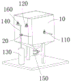
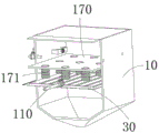
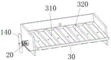
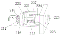
10. a treatment box body; 110. an air inlet pipe; 120. an exhaust pipe; 130. a gas tank; 140. a communicating pipe; 150. a discharge pipe; 160. a valve; 170. a carrying plate; 171. a dust removing cloth bag;
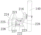
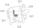
20. a transmission mechanism; 210. a transmission assembly; 211. a support plate; 212. a fan blade; 213. a rotating shaft; 214. bevel gears I; 215. bevel gears II; 216. a wire spool; 217. a turntable; 218. a conical block; 220. an air extraction assembly; 221. a first supporting plate; 222. a second supporting plate; 223. a guide rod; 224. connecting sleeves; 225. a piston; 226. a first guide rod; 227. a connecting plate; 228. a pull rope;
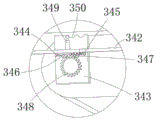
30. a mounting frame; 310. a partition rod; 320. a discharge chute; 330. a baffle; 331. a one-way valve; 340. an opening and closing assembly; 341. a push rod I; 342. a second push rod; 343. a mounting plate; 344. a first connecting block; 345. a second connecting block; 346. a second guide rod; 347. a rack; 348. a gear; 349. a push rod; 350. and a bump.
Detailed Description
The technical scheme of the invention is further described below by the specific embodiments with reference to the accompanying drawings.
Wherein the drawings are for illustrative purposes only and are shown in schematic, non-physical, and not intended to be limiting of the present patent; for the purpose of better illustrating embodiments of the invention, certain elements of the drawings may be omitted, enlarged or reduced and do not represent the size of the actual product; it will be appreciated by those skilled in the art that certain well-known structures in the drawings and descriptions thereof may be omitted.
The same or similar reference numbers in the drawings of embodiments of the invention correspond to the same or similar components; in the description of the present invention, it should be understood that, if the terms "upper", "lower", "left", "right", "inner", "outer", etc. indicate orientations or positional relationships based on the orientations or positional relationships shown in the drawings, only for convenience in describing the present invention and simplifying the description, rather than indicating or implying that the apparatus or elements being referred to must have a specific orientation, be constructed and operated in a specific orientation, so that the terms describing the positional relationships in the drawings are merely for exemplary illustration and should not be construed as limiting the present patent, and that the specific meaning of the terms described above may be understood by those of ordinary skill in the art according to specific circumstances.
In the description of the present invention, unless explicitly stated and limited otherwise, the term "coupled" or the like should be interpreted broadly, as it may be fixedly coupled, detachably coupled, or integrally formed, as indicating the relationship of components; can be mechanically or electrically connected; can be directly connected or indirectly connected through an intermediate medium, and can be communication between the two parts or interaction relationship between the two parts. The specific meaning of the above terms in the present invention will be understood in specific cases by those of ordinary skill in the art.
As shown in fig. 1 to 8, an anti-clogging clinker cement production line exhaust gas treatment apparatus and method thereof, comprising:
the treatment box body 10, the air inlet pipe 110, the exhaust pipe 120, the air tank 130, the communicating pipe 140, the exhaust pipe 150, the bearing plate 170 and the dust removing cloth bag 171, wherein the treatment box body 10 is arranged on the ground, the air inlet pipe 110 and the exhaust pipe 150 are communicated with the side wall of the treatment box body 10, the air tank 130 is arranged on one side of the treatment box body 10, high-pressure gas is stored in the air tank 130, one end of the communicating pipe 140 is communicated with the air tank 130, the other end of the communicating pipe 140 is communicated with the treatment box body 10, the exhaust end of the communicating pipe 140 is close to the top of the treatment box body 10, the exhaust pipe 150 is communicated with the bottom of the treatment box body 10, the valves 160 are arranged on the air inlet pipe 110, the exhaust pipe 120, the communicating pipe 140 and the exhaust pipe 150, the bearing plate 170 are horizontally and fixedly arranged in the treatment box body 10, the dust removing cloth bag 171 is arranged on the bearing plate 170, the dust removing cloth bag 171 is uniformly arranged on the bearing plate 170, the air inlet end of the exhaust pipe 120 and the exhaust end of the communicating pipe 140 are arranged above the bearing plate 170, and the air inlet end of the air inlet pipe 110 is arranged below the dust removing cloth bag 171;
the treatment box 10 is internally provided with a mounting frame 30 in a matching manner, the mounting frame 30 is internally provided with a plurality of partition rods 310 in a matching and fixing manner, the partition rods 310 are arranged at intervals uniformly along the length direction of the mounting frame 30, the partition rods 310 divide the mounting frame 30 into discharge tanks 320, the communicating pipes 140 are provided with transmission mechanisms 20, and the transmission mechanisms 20 are used for cleaning dust on the dust collection cloth bags 171.
More specifically, the transmission mechanism 20 includes a transmission assembly 210 and an air extraction assembly 220, the transmission assembly 210 includes a support plate 211, a fan blade 212, a rotating shaft 213, a first bevel gear 214, a second bevel gear 215, and a wire spool 216, the support plate 211 is horizontally and fixedly arranged in the communicating pipe 140, the fan blade 212 is mounted on the support plate 211, one end of the rotating shaft 213 is rotatably connected with the inner wall of the communicating pipe 140, the other end of the rotating shaft passes through the wall of the communicating pipe 140 and is fixedly connected with the wire spool 216 coaxially, the first bevel gear 214 is coaxially and fixedly sleeved on the rotating shaft 213, the second bevel gear 215 is coaxially and fixedly sleeved on the central shaft end of the fan blade 212, the first bevel gear 214 and the second bevel gear 215 are meshed, and the air extraction assembly 220 is connected with the wire spool 216.
More specifically, the air extraction assembly 220 includes a first support plate 221, a second support plate 222, a guide rod 223, a connecting sleeve 224, a piston 225, a first guide rod 226, and a pull rope 228, the first support plate 221 and the second support plate 222 are fixedly disposed on the side wall of the treatment box 10, the guide rod 223 is vertically and fixedly disposed between the first support plate 221 and the second support plate 222, the connecting sleeve 224 is fixedly disposed on the wall of the treatment box 10, the connecting sleeve 224 is in a cylindrical structure with two open ends, the connecting sleeve 224 is horizontally disposed, the piston 225 is disposed in the connecting sleeve 224 in a matching manner, the first guide rod 226 is disposed on one side of the connecting sleeve 224 in parallel, one end of the first guide rod 226 is fixedly connected with the side wall of the treatment box 10, an external step is disposed on the other end of the piston 225, the piston 225 is fixedly disposed on the first guide rod 226 through the connecting plate 227, one end of the spring is in contact with the connecting plate 227, the other end of the spring is in contact with the external step of the end of the first guide rod 226, the piston 225 is connected with the wire spool 216 through 228, and the pull rope 228 bypasses the guide rod 223, and the connecting rod 224 is disposed below the mounting frame 30.
More specifically, the baffle 330 is disposed in the discharge chute 320 of the mounting frame 30 in a matching manner, the baffle 330 is provided with an opening and closing assembly 340, the opening and closing assembly 340 comprises a mounting plate 343, a first connecting block 344, a second connecting block 345, a second guiding rod 346, a rack 347 and a gear 348, the mounting plate 343 is vertically and fixedly disposed at the bottom of the mounting frame 30 and near the end of the discharge chute 320, the mounting plate 343 is provided with two ends which are respectively disposed at the length direction of the discharge chute 320, the baffle 330 is rotatably mounted between the two mounting plates 343 through a connecting shaft, the first connecting block 344 and the second connecting block 345 are fixedly disposed on the surface of the mounting plate 343, the second guiding rod 346 is horizontally and fixedly disposed between the first connecting block 344 and the second connecting block 345, the rack 347 is sleeved on the second guiding rod 346 through a sliding sleeve, one end of the second guiding rod 346 is in contact with the sliding sleeve, the other end of the second spring contacts with the second connecting block 345, the gear 348 is coaxially and fixedly sleeved at the end of the connecting shaft 348, and the rack 347 is meshed with the gear 348.
More specifically, the rotating shaft 213 is coaxially and fixedly sleeved on the rotating disc 217, the disc surface of the rotating disc 217 is provided with a plurality of conical blocks 218, the conical blocks 218 are uniformly surrounded on the rotating disc 217, the top of the rack 347 is fixedly provided with a second push rod 342, the second push rod 342 is horizontally arranged, the second push rod 342 horizontally extends, the end part of the second push rod 342 is fixedly connected with a first push rod 341, and the end part of the first push rod 341 is close to the rotating disc 217 and is positioned between the two adjacent conical blocks 218.
More specifically, the top of the second push rod 342 is vertically provided with a push rod 349, the bottom of the frame of the installation frame 30 is fixedly provided with a bump 350, the top of the push rod 349 is close to the edge of the bump 350, and the push rod 349 is an elastic telescopic rod.
More specifically, the baffle 330 is provided with a check valve 331, and the drainage direction of the check valve 331 flows from above the mounting frame 30 to below the mounting frame 30.
More specifically, the sides of the partition rod 310 are arranged in an inclined manner, so that dust can slide down.
Working principle:
in the use process of the invention, waste gas enters the treatment box 10 through the air inlet pipe 110, then the waste gas is filtered and dedusted through the dedusting cloth bag 171, when more dust is adhered to the surface of the dedusting cloth bag 171, the valve 160 on the air inlet pipe 110 is closed, then the valve on the communicating pipe 140 is opened, high-pressure gas in the air tank 130 enters the treatment box 10 through the communicating pipe 140, then the dust on the surface of the dedusting cloth bag 171 is blown off by the high-pressure gas, the fan blade 212 is driven to rotate in the process of circulating through the communicating pipe 140, thereby the rotating shaft 213 is driven to rotate, the wire spool 216 is driven to rotate, the pull rope 228 is wound when the wire spool 216 rotates, the piston 225 is pulled to move in the connecting sleeve 224, so that the gas in the treatment box 10 can be extracted, the blowing force of the high-pressure gas to the dedusting cloth bag 171 is improved, the dust on the surface of the dedusting cloth bag 171 is facilitated to be blown off by the rotating shaft 213, the conical block 218 is driven to rotate around the rotary disk 217, then the conical surface of the conical block 218 is pushed against the first push rod 341, the push rod 342 is driven to move, then the second push rod 342 is driven to move along the guide rod 212, the guide rod 348 is driven to move along the rotating frame 320, then the top of the guide rod 346 is driven to move to the top of the frame 30, and the dust is blown off from the top of the frame 30 is driven to be blown off by the frame 349, and then the dust is driven to move the top of the frame 30 is driven to be blown off by the frame 320 to rotate, and then the frame 320 is driven to move the frame 320 to rotate, and the frame is rotated.
It should be understood that the above description is only illustrative of the preferred embodiments of the present invention and the technical principles employed. It will be apparent to those skilled in the art that various modifications, equivalents, variations, and the like can be made to the present invention. However, such modifications are intended to fall within the scope of the present invention without departing from the spirit of the present invention. In addition, some terms used in the specification and claims of the present application are not limiting, but are merely for convenience of description.
Claims (9)
1. An anti-clogging clinker cement production line exhaust gas treatment device, which is characterized by comprising:
the device comprises a treatment box body, an air inlet pipe, an air outlet pipe, an air tank, a communicating pipe, an air outlet pipe, a bearing plate and a dust removing cloth bag, wherein the treatment box body is arranged on the ground, the air inlet pipe and the air outlet pipe are communicated with the side wall of the treatment box body, the air tank is arranged on one side of the treatment box body, high-pressure gas is stored in the air tank, one end of the communicating pipe is communicated with the air tank, the other end of the communicating pipe is communicated with the treatment box body, the air outlet end of the communicating pipe is close to the top of the treatment box body, the air outlet pipe is communicated with the bottom of the treatment box body, valves are arranged on the air inlet pipe, the air outlet pipe, the communicating pipe and the air outlet pipe, the bearing plate are horizontally and fixedly arranged in the treatment box body, the dust removing cloth bag is arranged on the bearing plate, the dust removing cloth bag is provided with a plurality of dust removing cloth bags and is uniformly arranged on the bearing plate, the air inlet end of the air outlet pipe and the air outlet end of the communicating pipe are positioned above the bearing plate, and the air inlet end of the air inlet pipe is positioned below the dust removing cloth bag;
the processing box body is internally provided with a mounting frame in a matching manner, the mounting frame is internally provided with a plurality of partition rods in a matching manner, the partition rods are uniformly arranged at intervals along the length direction of the mounting frame, the partition rods divide the mounting frame into a discharge groove, a transmission mechanism is arranged on a communicating pipe, and the transmission mechanism is used for cleaning dust on a dust removing cloth bag.
2. The exhaust gas treatment device of the anti-blocking clinker cement production line according to claim 1, wherein the transmission mechanism comprises a transmission assembly and an air exhaust assembly, the transmission assembly comprises a support plate, a fan blade, a rotating shaft, a first bevel gear, a second bevel gear and a wire spool, the support plate is horizontally and fixedly arranged in the communicating pipe, the fan blade is arranged on the support plate, one end of the rotating shaft is rotatably connected with the inner wall of the communicating pipe, the other end of the rotating shaft penetrates through the wall of the communicating pipe and is fixedly connected with the wire spool coaxially, the first bevel gear is coaxially and fixedly sleeved on the rotating shaft, the second bevel gear is coaxially and fixedly sleeved on the central shaft end of the fan blade, the first bevel gear and the second bevel gear are meshed, and the air exhaust assembly is connected with the wire spool.
3. The exhaust gas treatment device of the anti-blocking clinker cement production line according to claim 2, wherein the exhaust gas treatment device comprises a first supporting plate, a second supporting plate, a guide rod, a connecting sleeve, a piston, a first guide rod and a pull rope, wherein the first supporting plate and the second supporting plate are fixedly arranged at the side wall of the treatment box body, the guide rod is vertically and fixedly arranged between the first supporting plate and the second supporting plate, the connecting sleeve is fixedly arranged on the wall of the treatment box body and is of a cylindrical structure with two open ends, the connecting sleeve is horizontally arranged, the piston is matched and arranged in the connecting sleeve, the first guide rod is arranged on one side of the connecting sleeve in parallel, one end of the first guide rod is fixedly connected with the side wall of the treatment box body, the other end of the piston is fixedly provided with a connecting plate, the piston is sleeved on the first guide rod through the connecting plate, one end of the first guide rod is sleeved with a spring, the other end of the spring is contacted with the connecting plate, the piston is connected with the wire winding disc through the pull rope, the guide rod is matched and the connecting sleeve is arranged below the installation frame.
4. The exhaust gas treatment device for the anti-blocking clinker cement production line is characterized in that a baffle is arranged in a discharge groove of a mounting frame in a matching manner, an opening and closing assembly is arranged on the baffle, the opening and closing assembly comprises a mounting plate, a first connecting block, a second guide rod, a rack and a gear, the mounting plate is vertically and fixedly arranged at the bottom of the mounting frame and near the end part of the discharge groove, the mounting plate is provided with two ends which are respectively arranged at the length direction of the discharge groove, the baffle is rotatably arranged between the two mounting plates through a connecting shaft, the first connecting block and the second connecting block are fixedly arranged on the surface of the mounting plate, the second guide rod is horizontally and fixedly arranged between the first connecting block and the second connecting block, the rack is sleeved on the second guide rod through a sliding sleeve, one end of the second spring is in contact with the sliding sleeve, the other end of the second guide rod is in contact with the second connecting block, the end part of the connecting shaft is coaxially and fixedly sleeved with the gear, and the rack is meshed with the gear.
5. The exhaust gas treatment device for the anti-blocking clinker cement production line according to claim 4, wherein the rotating shaft is coaxially and fixedly sleeved on the rotating disc, conical blocks are arranged on the disc surface of the rotating disc, the conical blocks are arranged in a plurality and uniformly surround the rotating disc, a second push rod is fixedly arranged at the top of the rack, the second push rod is horizontally arranged, the second push rod horizontally extends, the end part of the second push rod is fixedly connected with a first push rod, and the end part of the first push rod is close to the rotating disc and is positioned between two adjacent conical blocks.
6. The exhaust gas treatment device for the anti-clogging clinker cement production line according to claim 5, wherein a push rod is vertically arranged at the top of the second push rod, a bump is fixedly arranged at the bottom of the frame of the installation frame, the top of the push rod is close to the edge of the bump, and the push rod is an elastic telescopic rod.
7. The exhaust gas treatment device for an anti-clogging clinker cement production line according to claim 4, wherein the baffle plate is provided with a one-way valve, and the drainage direction of the one-way valve flows from above the mounting frame to below the mounting frame.
8. An anti-clogging clinker cement manufacturing line exhaust gas treatment apparatus as in claim 1 wherein the sides of the divider bars are disposed in an inclined arrangement.
9. A method of treating an anti-clogging clinker cement manufacturing line exhaust gas treatment apparatus according to any one of claims 1 to 8, the method comprising: the waste gas enters the treatment box body through the air inlet pipe, then the waste gas is filtered and dedusted through the dedusting cloth bag, when more dust is adhered to the surface of the dedusting cloth bag, a valve on the air inlet pipe is closed, then the valve on the communicating pipe is opened, high-pressure gas in the air tank enters the treatment box body through the communicating pipe, then the high-pressure gas blows off the dust on the surface of the dedusting cloth bag, the fan blades are driven to rotate in the process of circulating through the communicating pipe, so that the rotating shaft is driven to rotate, the wire reel is driven to rotate, the stay rope is wound when the wire reel rotates, so that the piston is pulled to move in the connecting sleeve, and the gas in the treatment box body can be extracted, so that the blowing force of the high-pressure gas to the dedusting cloth bag is improved;
the rotating shaft rotates to drive the carousel to rotate, thereby drive the toper piece and rotate round the carousel, the conical surface of toper piece is contradicted push rod one then, thereby order about push rod one and remove, thereby drive push rod two and remove, then drive rack and remove along guide bar two, thereby drive gear rotation, then drive baffle deflection, the discharge groove is opened, dust on dust removal sack surface can fall to the discharge inslot, get into the bottom of handling the box and discharge through the discharge pipe afterwards, the in-process that push rod two removed drives the ejector pin and removes, the top of ejector pin is knocked the frame of installing frame after contradicting the lug, thereby shake off the dust that will fall to the installing frame.
Priority Applications (1)
| Application Number | Priority Date | Filing Date | Title |
|---|---|---|---|
| CN202310497701.XA CN116196705B (en) | 2023-05-06 | 2023-05-06 | Anti-blocking clinker cement production line waste gas treatment device and method |
Applications Claiming Priority (1)
| Application Number | Priority Date | Filing Date | Title |
|---|---|---|---|
| CN202310497701.XA CN116196705B (en) | 2023-05-06 | 2023-05-06 | Anti-blocking clinker cement production line waste gas treatment device and method |
Publications (2)
| Publication Number | Publication Date |
|---|---|
| CN116196705A true CN116196705A (en) | 2023-06-02 |
| CN116196705B CN116196705B (en) | 2023-07-21 |
Family
ID=86509870
Family Applications (1)
| Application Number | Title | Priority Date | Filing Date |
|---|---|---|---|
| CN202310497701.XA Active CN116196705B (en) | 2023-05-06 | 2023-05-06 | Anti-blocking clinker cement production line waste gas treatment device and method |
Country Status (1)
| Country | Link |
|---|---|
| CN (1) | CN116196705B (en) |
Citations (14)
| Publication number | Priority date | Publication date | Assignee | Title |
|---|---|---|---|---|
| CN207562538U (en) * | 2017-11-17 | 2018-07-03 | 广州市汇邦动物药业有限公司 | A kind of pulse bag formula deduster |
| KR102054738B1 (en) * | 2019-09-06 | 2019-12-11 | 고성득 | Dust collecting device |
| CN110960934A (en) * | 2019-10-24 | 2020-04-07 | 陈锦勇 | Environmental protection exhaust system that can remove dust for boiler of thermal power factory |
| CN112169470A (en) * | 2020-10-20 | 2021-01-05 | 张曼玲 | Cloth belt dust remover capable of reducing pulse air injection frequency |
| CN112675626A (en) * | 2021-03-12 | 2021-04-20 | 佛山市绿源亚太环保设备科技有限公司 | Intelligent dust collector for flue gas cloth bag |
| CN215962609U (en) * | 2021-11-03 | 2022-03-08 | 河北中润轩机械设备有限公司 | Novel blast furnace gas cloth bag dust remover |
| CN114504891A (en) * | 2022-02-16 | 2022-05-17 | 安徽华宇机械制造有限公司 | Pulse dust collector based on vibrating deashing structure |
| CN216841982U (en) * | 2022-01-08 | 2022-06-28 | 江西箭冠科技有限公司 | Air filter |
| CN217431134U (en) * | 2022-06-06 | 2022-09-16 | 扬州市扬江机械设备工程有限公司 | Grain pulse high-pressure dust remover |
| CN217909424U (en) * | 2022-07-12 | 2022-11-29 | 内蒙古和兴利食品股份有限公司 | High-fiber meal replacement powder processing pulse dust collector |
| CN115634523A (en) * | 2022-11-23 | 2023-01-24 | 江苏江龙新能源科技有限公司 | Dust collector is used in graphite electrode production |
| CN115671879A (en) * | 2022-10-25 | 2023-02-03 | 陈玉林 | Desulfurization and demisting system and method for coal-fired boiler |
| CN218687365U (en) * | 2022-09-06 | 2023-03-24 | 湘乡机械厂有限责任公司 | Low-pressure pulse long-bag dust collector |
| CN115852663A (en) * | 2022-12-30 | 2023-03-28 | 李林 | Textile fabric cleaning system and method for textile equipment |
-
2023
- 2023-05-06 CN CN202310497701.XA patent/CN116196705B/en active Active
Patent Citations (14)
| Publication number | Priority date | Publication date | Assignee | Title |
|---|---|---|---|---|
| CN207562538U (en) * | 2017-11-17 | 2018-07-03 | 广州市汇邦动物药业有限公司 | A kind of pulse bag formula deduster |
| KR102054738B1 (en) * | 2019-09-06 | 2019-12-11 | 고성득 | Dust collecting device |
| CN110960934A (en) * | 2019-10-24 | 2020-04-07 | 陈锦勇 | Environmental protection exhaust system that can remove dust for boiler of thermal power factory |
| CN112169470A (en) * | 2020-10-20 | 2021-01-05 | 张曼玲 | Cloth belt dust remover capable of reducing pulse air injection frequency |
| CN112675626A (en) * | 2021-03-12 | 2021-04-20 | 佛山市绿源亚太环保设备科技有限公司 | Intelligent dust collector for flue gas cloth bag |
| CN215962609U (en) * | 2021-11-03 | 2022-03-08 | 河北中润轩机械设备有限公司 | Novel blast furnace gas cloth bag dust remover |
| CN216841982U (en) * | 2022-01-08 | 2022-06-28 | 江西箭冠科技有限公司 | Air filter |
| CN114504891A (en) * | 2022-02-16 | 2022-05-17 | 安徽华宇机械制造有限公司 | Pulse dust collector based on vibrating deashing structure |
| CN217431134U (en) * | 2022-06-06 | 2022-09-16 | 扬州市扬江机械设备工程有限公司 | Grain pulse high-pressure dust remover |
| CN217909424U (en) * | 2022-07-12 | 2022-11-29 | 内蒙古和兴利食品股份有限公司 | High-fiber meal replacement powder processing pulse dust collector |
| CN218687365U (en) * | 2022-09-06 | 2023-03-24 | 湘乡机械厂有限责任公司 | Low-pressure pulse long-bag dust collector |
| CN115671879A (en) * | 2022-10-25 | 2023-02-03 | 陈玉林 | Desulfurization and demisting system and method for coal-fired boiler |
| CN115634523A (en) * | 2022-11-23 | 2023-01-24 | 江苏江龙新能源科技有限公司 | Dust collector is used in graphite electrode production |
| CN115852663A (en) * | 2022-12-30 | 2023-03-28 | 李林 | Textile fabric cleaning system and method for textile equipment |
Also Published As
| Publication number | Publication date |
|---|---|
| CN116196705B (en) | 2023-07-21 |
Similar Documents
| Publication | Publication Date | Title |
|---|---|---|
| CN107051674B (en) | A kind of discarded stone brick crushing device in construction site | |
| CN208288243U (en) | A kind of quartz sand multistage purification device | |
| CN108487442A (en) | A kind of rubbish for municipal sewer cleaning removes equipment | |
| CN209372586U (en) | A kind of pressure testing machine with protection and cleaning function | |
| CN108942633A (en) | Polishing rust-removal equipment and polishing process | |
| CN109372092A (en) | A kind of sewage lifting device to remove slag | |
| CN109847489A (en) | A kind of deduster | |
| CN108465307A (en) | A kind of industrial fumes dust-removing and purifying method | |
| CN116196705B (en) | Anti-blocking clinker cement production line waste gas treatment device and method | |
| CN108505612A (en) | A kind of well lid of municipal sewer cleaning vehicle opens structure | |
| CN107012711B (en) | A kind of paper mill pulp filtering device for paper | |
| CN109108259B (en) | Foundry goods processing is with shakeout device convenient to even feeding | |
| CN107551583A (en) | A kind of drying device for rare earth chloride | |
| CN108568513B (en) | A kind of casting desanding device | |
| CN106925022B (en) | A kind of rotary-type dehydration device for carbonated rare earth | |
| CN206881222U (en) | A kind of mud scraper | |
| CN214488017U (en) | Automatic brucite powder production equipment | |
| CN206276601U (en) | A kind of steel structure shot blast particles washing flow line equipment | |
| CN108517951A (en) | One kind being used for the hard object plugging handling equipment of municipal sewer | |
| CN114289403A (en) | Single crystal silicon rod glue removing and removing mechanism with low wear rate | |
| CN107855264A (en) | A kind of scrap iron recovery processing unit | |
| CN209452462U (en) | A kind of workshop cleaner | |
| CN207493998U (en) | A kind of wind washing machine | |
| CN112332256A (en) | Electric control cabinet under chemical industry environment | |
| CN208082093U (en) | A kind of dust cleaning device producing boron carbide workshop |
Legal Events
| Date | Code | Title | Description |
|---|---|---|---|
| PB01 | Publication | ||
| PB01 | Publication | ||
| SE01 | Entry into force of request for substantive examination | ||
| SE01 | Entry into force of request for substantive examination | ||
| GR01 | Patent grant | ||
| GR01 | Patent grant |