CN116190879B - Combined type electric energy storage device and combination method thereof - Google Patents
Combined type electric energy storage device and combination method thereof Download PDFInfo
- Publication number
- CN116190879B CN116190879B CN202310446107.8A CN202310446107A CN116190879B CN 116190879 B CN116190879 B CN 116190879B CN 202310446107 A CN202310446107 A CN 202310446107A CN 116190879 B CN116190879 B CN 116190879B
- Authority
- CN
- China
- Prior art keywords
- pair
- fixed
- inner box
- elliptical
- shaped
- Prior art date
- Legal status (The legal status is an assumption and is not a legal conclusion. Google has not performed a legal analysis and makes no representation as to the accuracy of the status listed.)
- Active
Links
Images


Classifications
-
- H—ELECTRICITY
- H01—ELECTRIC ELEMENTS
- H01M—PROCESSES OR MEANS, e.g. BATTERIES, FOR THE DIRECT CONVERSION OF CHEMICAL ENERGY INTO ELECTRICAL ENERGY
- H01M50/00—Constructional details or processes of manufacture of the non-active parts of electrochemical cells other than fuel cells, e.g. hybrid cells
- H01M50/20—Mountings; Secondary casings or frames; Racks, modules or packs; Suspension devices; Shock absorbers; Transport or carrying devices; Holders
- H01M50/204—Racks, modules or packs for multiple batteries or multiple cells
-
- H—ELECTRICITY
- H01—ELECTRIC ELEMENTS
- H01M—PROCESSES OR MEANS, e.g. BATTERIES, FOR THE DIRECT CONVERSION OF CHEMICAL ENERGY INTO ELECTRICAL ENERGY
- H01M50/00—Constructional details or processes of manufacture of the non-active parts of electrochemical cells other than fuel cells, e.g. hybrid cells
- H01M50/20—Mountings; Secondary casings or frames; Racks, modules or packs; Suspension devices; Shock absorbers; Transport or carrying devices; Holders
- H01M50/233—Mountings; Secondary casings or frames; Racks, modules or packs; Suspension devices; Shock absorbers; Transport or carrying devices; Holders characterised by physical properties of casings or racks, e.g. dimensions
- H01M50/242—Mountings; Secondary casings or frames; Racks, modules or packs; Suspension devices; Shock absorbers; Transport or carrying devices; Holders characterised by physical properties of casings or racks, e.g. dimensions adapted for protecting batteries against vibrations, collision impact or swelling
-
- H—ELECTRICITY
- H01—ELECTRIC ELEMENTS
- H01M—PROCESSES OR MEANS, e.g. BATTERIES, FOR THE DIRECT CONVERSION OF CHEMICAL ENERGY INTO ELECTRICAL ENERGY
- H01M50/00—Constructional details or processes of manufacture of the non-active parts of electrochemical cells other than fuel cells, e.g. hybrid cells
- H01M50/20—Mountings; Secondary casings or frames; Racks, modules or packs; Suspension devices; Shock absorbers; Transport or carrying devices; Holders
- H01M50/244—Secondary casings; Racks; Suspension devices; Carrying devices; Holders characterised by their mounting method
-
- H—ELECTRICITY
- H01—ELECTRIC ELEMENTS
- H01M—PROCESSES OR MEANS, e.g. BATTERIES, FOR THE DIRECT CONVERSION OF CHEMICAL ENERGY INTO ELECTRICAL ENERGY
- H01M50/00—Constructional details or processes of manufacture of the non-active parts of electrochemical cells other than fuel cells, e.g. hybrid cells
- H01M50/20—Mountings; Secondary casings or frames; Racks, modules or packs; Suspension devices; Shock absorbers; Transport or carrying devices; Holders
- H01M50/262—Mountings; Secondary casings or frames; Racks, modules or packs; Suspension devices; Shock absorbers; Transport or carrying devices; Holders with fastening means, e.g. locks
- H01M50/264—Mountings; Secondary casings or frames; Racks, modules or packs; Suspension devices; Shock absorbers; Transport or carrying devices; Holders with fastening means, e.g. locks for cells or batteries, e.g. straps, tie rods or peripheral frames
-
- Y—GENERAL TAGGING OF NEW TECHNOLOGICAL DEVELOPMENTS; GENERAL TAGGING OF CROSS-SECTIONAL TECHNOLOGIES SPANNING OVER SEVERAL SECTIONS OF THE IPC; TECHNICAL SUBJECTS COVERED BY FORMER USPC CROSS-REFERENCE ART COLLECTIONS [XRACs] AND DIGESTS
- Y02—TECHNOLOGIES OR APPLICATIONS FOR MITIGATION OR ADAPTATION AGAINST CLIMATE CHANGE
- Y02E—REDUCTION OF GREENHOUSE GAS [GHG] EMISSIONS, RELATED TO ENERGY GENERATION, TRANSMISSION OR DISTRIBUTION
- Y02E60/00—Enabling technologies; Technologies with a potential or indirect contribution to GHG emissions mitigation
- Y02E60/10—Energy storage using batteries
Landscapes
- Chemical & Material Sciences (AREA)
- Chemical Kinetics & Catalysis (AREA)
- Electrochemistry (AREA)
- General Chemical & Material Sciences (AREA)
- Battery Mounting, Suspending (AREA)
Abstract
The utility model discloses a combined electric energy storage device and a combination method thereof, and relates to the technical field of electric energy storage, and the combined electric energy storage device comprises an open box, wherein a plurality of fixed shafts are arranged on the inner bottom wall of the open box, a fixed disc is fixedly arranged at the top end part of the fixed shaft, an inner box is arranged above the fixed disc, elliptical blocks are fixedly arranged at corners of the bottom surface of the inner box, four elliptical sleeves are arranged on the outer ring surface of the fixed disc, and the elliptical blocks are matched and inserted in the corresponding elliptical sleeves; the middle part of the inner bottom wall of the inner box is fixedly provided with a cross plate, the cross plate and the inner box form four fixed cavities, the inner bottom of each fixed cavity is provided with a storage battery, the four included angles of the cross plate are internally provided with L-shaped clamping plates, and the cross plate is connected with the four L-shaped clamping plates through a clamping mechanism; four trapezoidal cover plates are arranged at the opening of the top surface of the inner box, and the inner box is connected with the four trapezoidal cover plates through a hinge assembly. The utility model can carry out batch installation on the storage batteries, ensures the stability of the storage batteries during installation and improves the safety performance of the combined use of the storage batteries.
Description
Technical Field
The present utility model relates to the field of electric energy storage technologies, and in particular, to a combined electric energy storage device and a combination method thereof.
Background
The utility model discloses a combined energy storage battery box (publication number: CN 218351627U), which comprises a shell body and a built-in frame body which is slidably arranged in the shell body, wherein a plurality of battery placing boxes are fixedly arranged in the built-in frame body, a plurality of buffer cotton bodies are arranged in the built-in frame body and are respectively and fixedly arranged among the battery placing boxes, a guide assembly is arranged in the shell body, when the shell body receives collision, the shell body primarily protects the built-in frame body in the shell body, vibration generated at the same time can be absorbed by the plurality of buffer cotton bodies in the built-in frame body and outside the battery placing boxes, a better protection effect is achieved, a rotating rod is used for driving a gear to rotate, the gear drives a toothed bar at the top and the bottom to move, so that the connecting frame body is controlled to be outwards extended out of the toothed bar to be clamped and fixed with a clamping groove, meanwhile, a supporting spring is used for supporting the toothed bar, and the extension end of the toothed bar is prevented from being separated from and fixed with the clamping groove.
When the front storage battery is installed, the following disadvantages exist: 1. the storage battery storage device is not convenient to install and can not be used for conveniently assembling and disassembling the internal energy storage battery, and the replacement of the internal battery is troublesome; 2. the storage battery is easy to damage the internal energy storage battery due to external collision during installation, and a certain buffering protection effect is lacked.
Disclosure of Invention
The utility model aims to solve the defects of weak installation and easy damage of a storage battery combination in the prior art, and provides a combined type electric energy storage device and a combination method thereof.
In order to solve the problems of the prior art that the assembled installation of the storage battery is not firm and is easy to damage, the utility model adopts the following technical scheme:
the combined electric energy storage device comprises an open box, wherein a plurality of evenly arranged fixed shafts which are rotationally connected are inserted into the inner bottom wall of the open box, a fixed disc which is concentrically fixedly connected is fixedly arranged at the top end of the fixed shaft, an inner box with an open top surface is arranged above the fixed disc, oval blocks are fixedly arranged at corners of the bottom surface of the inner box, four oval sleeves which are circularly arranged are arranged on the outer ring surface of the fixed disc, the bottom surface of each oval sleeve is fixedly connected with the inner bottom wall of the open box, and each oval block is matched and inserted into the corresponding oval sleeve;
the middle part of the inner bottom wall of the inner box is fixedly provided with a cross plate, four outer side edges of the cross plate are fixedly connected with four inner side walls of the inner box, the cross plate and the inner box form four fixed cavities, a storage battery is arranged at the inner bottom of each fixed cavity, L-shaped clamping plates are arranged in four included angles of the cross plate, the bottom wall of each L-shaped clamping plate is in sliding connection with the inner bottom wall of the fixed cavity, and the cross plate is connected with the four L-shaped clamping plates through a clamping mechanism; four trapezoid cover plates are arranged at the opening of the top surface of the inner box, and the inner box is connected with the four trapezoid cover plates through a hinge assembly.
Preferably, the middle parts of the oval sleeve and the oval block are provided with continuous through bolt through holes, four circularly arranged rectangular rings are arranged between the fixed disc and the four oval sleeves, the bottom surface of each rectangular ring is fixedly connected with the inner bottom wall of the open box, each rectangular ring is internally inserted with a sliding through rectangular sliding plate, the outer end part of each rectangular sliding plate is fixedly provided with an L-shaped inserted rod, and the outer section part of each L-shaped inserted rod is penetrated in the corresponding bolt through hole.
Preferably, four limit pin holes which are circularly arranged are formed in the top surface of the fixed disc, the inner section part of the rectangular sliding plate extends to the lower part of the bottom surface of the fixed disc, a limit pin shaft which is vertically and fixedly connected is arranged at the inner end part of the rectangular sliding plate, and the top end part of the limit pin shaft is inserted into the corresponding limit pin hole;
an arc-shaped rack is fixedly arranged on one side of the fixed disc and is meshed with the gear, the middle part of the bottom surface of the gear is fixedly connected with the end part of a motor shaft of the micro-control motor, and the bottom of the micro-control motor is fixedly connected with the inner bottom wall of the open box.
Preferably, the clamping mechanism comprises an H-shaped connecting rod, a rectangular cavity is formed in the middle lower portion of the inside of the cross plate, a vertically-rotating connected screw rod is inserted into the rectangular cavity, a threaded cylinder in threaded connection is sleeved on the upper section of the screw rod, the threaded cylinder is in a hollow cylinder shape with an outer square and an inner round, rectangular sliding holes are formed in the side walls of four included angles of the cross plate, and each rectangular sliding hole is communicated with the rectangular cavity;
every the inside of rectangle slide hole all is equipped with a pair of oblique slip and runs through and the H type connecting rod of parallel arrangement, every pair of the inner tip of H type connecting rod all articulates with the outer wall activity of screw thread section of thick bamboo, every pair of the outer tip of H type connecting rod all articulates with the chamfer side of corresponding L type splint.
Preferably, the bottom end part of the screw rod extends to the lower part of the inner box, the bottom end part of the screw rod is provided with a coaxially-connected polygonal shaft, the middle part of the top surface of the fixed disc is provided with a polygonal sleeve concentrically fixedly connected, and the bottom of the polygonal shaft is slidably inserted in the polygonal sleeve.
Preferably, a pair of inner liners are fixedly arranged on two side walls of the included angle in the L-shaped clamping plate, trapezoid buffer plates vertically fixedly connected are arranged at the corners of the inner side wall of the inner box, a pair of outer liners are fixedly arranged on the inner side walls of the fixed cavity, the outer liners are respectively arranged on two sides of the corresponding trapezoid buffer plates in a vertical state, and the outer liners and the inner liners surround the storage battery and are propped against the outer side wall of the storage battery.
Preferably, the collecting ring has been set firmly in the bottom surface middle part of inner box, four oval through-holes have been seted up to the bottom surface of inner box, four oval through-holes is circular arrangement around the collecting ring, every oval through-hole's interior middle part all is equipped with sliding connection's power connection, every power connection's top all is pegged graft with the bottom surface middle part of corresponding battery electricity, every power connection's bottom passes through insulated wire and collecting ring electric connection.
Preferably, the hinge assembly comprises an L-shaped pin shaft, widened lug seats are fixedly arranged in the middle of the four top edges of the inner box, a pair of fixed lug seats are fixedly arranged on two sides of the outer edge of the trapezoid cover plate, a pair of fixed lug seats are uniformly arranged on two sides of the widened lug seats, and each widened lug seat is movably hinged with the pair of fixed lug seats through the hinge pin shaft;
a pair of swing ear seats are fixedly arranged at two corners of the outer edge of the trapezoid cover plate, a pair of positioning pin holes are formed in the outer end portions of the swing ear seats, each pair of swing ear seats are movably hinged with the adjacent pair of swing ear seats through a pair of L-shaped pin shafts, and the two end portions of each pair of L-shaped pin shafts are inserted into the corresponding positioning pin holes.
Preferably, each trapezoid cover plate is provided with an arc notch at the corner of the inner side of the top surface, a threaded hole is formed in the middle of the top surface of the cross plate, a fixing bolt is inserted into the threaded hole, and the fixing bolts are sequentially abutted to the corresponding four arc notches.
The utility model also provides a combination method of the combined electric energy storage device, which comprises the following steps:
step one, every four storage batteries are in a group, and are placed in four fixed cavities of an inner box, so that the storage batteries are electrically connected with a power connector in an inserting mode; four trapezoid cover plates are synchronously covered, each pair of L-shaped pin shafts and two adjacent pairs of swinging lug seats form a limiting effect, the four trapezoid cover plates are driven to be synchronously closed, and then the four trapezoid cover plates are locked and fixed through fixing bolts;
step two, the inner box is placed in the open box, four elliptic blocks are matched and inserted into corresponding elliptic sleeves, and polygonal shafts are inserted into corresponding polygonal sleeves; the motor shaft of the micro-control motor is controlled to drive the gear to rotate slowly, and the gear is meshed to drive the arc-shaped rack, the fixed disc, the fixed shaft and the polygonal sleeve to rotate;
step three, when the fixed disc rotates, the limiting pin shaft and the limiting pin hole form a limiting effect, the rectangular sliding plate is driven to slide outwards along the rectangular ring, and the outer section part of the L-shaped inserted rod is driven to penetrate through the corresponding inserted pin through hole, so that the oval block and the oval sleeve are clamped and fixed;
driving the polygonal shaft and the screw rod to synchronously rotate when the polygonal sleeve rotates, driving the screw rod and the screw thread cylinder to slowly move downwards under the spiral action of the screw rod and the screw thread cylinder, driving each pair of H-shaped connecting rods to downwards slide in the corresponding rectangular sliding holes, and driving the L-shaped clamping plates to horizontally move towards the storage battery under the cooperation of the hinging action, so as to synchronously drive the pair of outer gaskets and the pair of inner gaskets to prop against the outer side wall of the storage battery;
and fifthly, repeating the steps, sequentially installing and fixing the storage battery and the inner box, and connecting a plurality of collector rings in series in a wired mode.
Compared with the prior art, the utility model has the beneficial effects that:
1. according to the utility model, through the matched use of the clamping mechanisms, the L-shaped clamping plate is driven to translate towards the storage battery, and the pair of outer gaskets and the pair of inner gaskets are synchronously driven to abut against the outer side wall of the storage battery, so that the clamping and fixing of the storage battery are realized, the stability of the storage battery in a fixed cavity is ensured, collision damage during the fixing or transportation of the storage battery is avoided, and the service life of the storage battery is prolonged;
2. according to the utility model, the limiting pin shaft and the limiting pin hole form a limiting effect, and the outer section part of the L-shaped inserted rod is driven to penetrate through and be arranged in the corresponding bolt through hole, so that the elliptical block and the elliptical sleeve are clamped and fixed, the stability of the installation of the inner box in the open box is ensured, and the batch installation and fixation of the storage battery can be realized;
in summary, the utility model solves the problems of unstable and easy damage of the assembled installation of the storage battery, has compact overall structural design, can carry out batch installation on the storage battery, ensures the stability of the storage battery during the installation and improves the safety performance of the assembled use of the storage battery.
Drawings
The accompanying drawings, which are included to provide a further understanding of the utility model and are incorporated in and constitute a part of this application, illustrate embodiments of the utility model and together with the description serve to explain the utility model and do not constitute a limitation on the utility model. In the drawings:
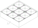
FIG. 1 is a schematic diagram of a front view of the present utility model;
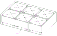
FIG. 2 is a schematic view of a front view of the present utility model;
FIG. 3 is an open schematic of the open box of the present utility model;
FIG. 4 is a schematic view of the structure of the inner case of the present utility model;
FIG. 5 is a schematic bottom view of the inner box of the present utility model;
FIG. 6 is an exploded view of FIG. 4 in accordance with the present utility model;
FIG. 7 is an exploded view of FIG. 5 in accordance with the present utility model;
FIG. 8 is an isometric cutaway schematic view of the inner box of the present utility model;
FIG. 9 is a schematic view of a clamping mechanism according to the present utility model;
FIG. 10 is a schematic diagram of the connection of the collector ring to four batteries of the present utility model;
number in the figure: 1. an open box; 11. an arc-shaped rack; 12. a gear; 13. a micro-control motor; 14. a rectangular ring; 15. a rectangular slide plate; 16. limiting pin shafts; 17. a polygonal sleeve; 18. a fixed plate; 19. an L-shaped inserted link; 110. an elliptical sleeve; 2. an inner box; 21. widening the ear seat; 22. fixing the ear seat; 23. a fixing bolt; 24. a trapezoidal cover plate; 25. swinging the ear seat; 26. an L-shaped pin shaft; 27. an elliptic block; 28. a fixed shaft; 3. a cross plate; 31. an L-shaped clamping plate; 32. an inner liner; 33. an outer liner; 34. a trapezoidal buffer plate; 35. a screw rod; 36. a polygonal shaft; 37. an H-shaped connecting rod; 38. a thread cylinder; 4. a power supply connector; 41. a storage battery; 42. an insulating wire; 43. and a collecting ring.
Detailed Description
The following description of the embodiments of the present utility model will be made clearly and completely with reference to the accompanying drawings, in which it is apparent that the embodiments described are only some embodiments of the present utility model, but not all embodiments.
Embodiment one: the embodiment provides a combined electric energy storage device, referring to fig. 1-10, specifically, the combined electric energy storage device comprises an open box 1, wherein a plurality of evenly arranged fixed shafts 28 which are rotationally connected are inserted into the inner bottom wall of the open box 1, a fixed disk 18 which is concentrically fixedly connected is fixedly arranged at the top end part of the fixed shaft 28, an inner box 2 with an open top surface is arranged above the fixed disk 18, elliptical blocks 27 are fixedly arranged at corners of the bottom surface of the inner box 2, four circularly arranged elliptical sleeves 110 are arranged on the outer ring surface of the fixed disk 18, the bottom surface of each elliptical sleeve 110 is fixedly connected with the inner bottom wall of the open box 1, and each elliptical block 27 is matched and inserted into the corresponding elliptical sleeve 110;
the middle part of the inner bottom wall of the inner box 2 is fixedly provided with a cross plate 3, four outer side edges of the cross plate 3 are fixedly connected with four inner side walls of the inner box 2, the cross plate 3 and the inner box 2 form four fixed cavities, the inner bottom of each fixed cavity is provided with a storage battery 41, the four included angles of the cross plate 3 are internally provided with L-shaped clamping plates 31, the bottom wall of each L-shaped clamping plate 31 is in sliding connection with the inner bottom wall of the fixed cavity, and the cross plate 3 is connected with the four L-shaped clamping plates 31 through a clamping mechanism; four trapezoid cover plates 24 are arranged at the opening of the top surface of the inner box 2, and the inner box 2 is connected with the four trapezoid cover plates 24 through a hinge assembly.
In the specific implementation process, as shown in fig. 8 and 10, a collecting ring 43 is fixedly arranged in the middle of the bottom surface of the inner box 2, four elliptical through holes are formed in the bottom surface of the inner box 2, the four elliptical through holes are circularly arranged around the collecting ring 43, a power connector 4 in sliding connection is arranged in the middle of the inner part of each elliptical through hole, the top end part of each power connector 4 is electrically connected with the middle of the bottom surface of the corresponding storage battery 41 in an inserting manner, and the bottom end part of each power connector 4 is electrically connected with the collecting ring 43 through an insulating wire 42;
the storage battery 41 is electrically connected with the power connector 4 in an inserting mode, when the storage battery 41 is clamped and fixed, the storage battery 41 can translate, the power connector 4 can be driven to slide along the elliptical through hole, the stability of the electric connection between the storage battery 41 and the collecting rings 43 is guaranteed, and then the collecting rings 43 are connected in series in a wired mode for use.
The description is as follows: in this embodiment, a pair of inner liners 32 are fixedly arranged on two side walls of an included angle in the L-shaped clamping plate 31, a trapezoid buffer plate 34 fixedly connected vertically is arranged at the corner of the inner side wall of the inner box 2, a pair of outer liners 33 are fixedly arranged on two inner side walls of the fixed cavity, the pair of outer liners 33 are respectively arranged on two sides of the trapezoid buffer plate 34 in a vertical state, and the pair of outer liners 33 and the pair of inner liners 32 surround the storage battery 41 and are propped against the outer side wall of the storage battery 41;
the pair of outer gaskets 33 and the pair of inner gaskets 32 are made of rubber cushion materials, so that the storage battery 41 is effectively protected, collision damage during fixing or transportation of the storage battery 41 is avoided, and the service life of the storage battery 41 is prolonged.
Embodiment two: in the first embodiment, there is also a problem that the battery 41 is not firmly fixed in the fixing cavity, and therefore, the present embodiment further includes, on the basis of the first embodiment:
in the specific implementation process, as shown in fig. 8 and 9, the clamping mechanism comprises an H-shaped connecting rod 37, a rectangular cavity is formed in the middle lower part in the cross plate 3, a screw rod 35 in vertical rotation connection is inserted into the rectangular cavity, a threaded cylinder 38 in threaded connection is sleeved on the upper section of the screw rod 35, the threaded cylinder 38 is in a hollow cylinder shape with an outer square and an inner round, rectangular sliding holes are formed in the side walls of four included angles of the cross plate 3, and each rectangular sliding hole is communicated with the rectangular cavity;
a pair of H-shaped connecting rods 37 which are obliquely and slidably penetrated and are arranged in parallel are arranged in each rectangular sliding hole, the inner end parts of the H-shaped connecting rods 37 of each pair are movably hinged with the outer wall of the threaded cylinder 38, and the outer end parts of the H-shaped connecting rods 37 of each pair are movably hinged with the chamfer sides of the corresponding L-shaped clamping plates 31;
the bottom end part of the screw rod 35 extends to the lower part of the inner box 2, the bottom end part of the screw rod 35 is provided with a coaxially connected polygonal shaft 36, the middle part of the top surface of the fixed disc 18 is provided with a concentric fixedly connected polygonal sleeve 17, and the bottom of the polygonal shaft 36 is inserted in the polygonal sleeve 17 in a sliding way;
when the polygonal sleeve 17 rotates, the polygonal shaft 36 and the lead screw 35 are driven to synchronously rotate, the screw 35 and the screw barrel 38 are driven to slowly move downwards by the screw action of the lead screw 35 and the screw barrel 38, each pair of H-shaped connecting rods 37 are driven to downwardly slide in the corresponding rectangular sliding holes, the L-shaped clamping plates 31 are driven to horizontally move towards the storage battery 41 under the cooperation of the hinging action, the pair of outer gaskets 33 and the pair of inner gaskets 32 are synchronously driven to abut against the outer side walls of the storage battery 41, the clamping and fixing of the storage battery 41 are further realized, and the mounting stability of the storage battery 41 in a fixed cavity is ensured.
Embodiment III: in the first embodiment, there is also a problem that the inner case 2 is not firmly fixed in the opening, and therefore, the present embodiment further includes, on the basis of the first embodiment:
in the specific implementation process, as shown in fig. 6 and 7, the middle parts of the elliptical sleeves 110 and the elliptical blocks 27 are provided with continuous through bolt through holes, four circularly arranged rectangular rings 14 are arranged between the fixed disc 18 and the four elliptical sleeves 110, the bottom surface of each rectangular ring 14 is fixedly connected with the inner bottom wall of the open box 1, each rectangular ring 14 is internally inserted with a sliding through rectangular sliding plate 15, the outer end part of each rectangular sliding plate 15 is fixedly provided with an L-shaped inserted rod 19, and the outer section part of each L-shaped inserted rod 19 is internally and uniformly inserted in the corresponding bolt through hole;
four limit pin holes which are circularly arranged are formed in the top surface of the fixed disc 18, the inner section of the rectangular sliding plate 15 extends to the lower part of the bottom surface of the fixed disc 18, a limit pin shaft 16 which is vertically fixedly connected is arranged at the inner end part of the rectangular sliding plate 15, and the top end part of the limit pin shaft 16 is inserted into the corresponding limit pin hole;
an arc-shaped rack 11 is fixedly arranged on one side of the fixed disc 18, the arc-shaped rack 11 is meshed with the gear 12, the middle part of the bottom surface of the gear 12 is fixedly connected with the end part of a motor shaft of the micro-control motor 13, and the bottom of the micro-control motor 13 is fixedly connected with the inner bottom wall of the open box 1;
the motor shaft of the micro-control motor 13 is controlled to drive the gear 12 to rotate slowly, and the gear 12 is meshed to drive the arc-shaped rack 11, the fixed disc 18, the fixed shaft 28 and the polygonal sleeve 17 to rotate;
when the fixed disk 18 rotates, the limiting pin shaft 16 and the limiting pin hole form a limiting effect, the rectangular sliding plate 15 is driven to slide outwards along the rectangular ring 14, and the outer section part of the L-shaped inserted rod 19 is driven to penetrate through and be arranged in the corresponding bolt through hole, so that the elliptical block 27 and the elliptical sleeve 110 are clamped and fixed, further the limiting fixation of the inner box 2 is realized, and the installation stability of the inner box 2 in the open box 1 is ensured.
Embodiment four: in the first embodiment, there is also a problem that the four trapezoidal cover plates 24 are easy to be opened, so the present embodiment further includes, on the basis of the first embodiment:
in a specific implementation process, as shown in fig. 4 and 6, the hinge assembly comprises an L-shaped pin shaft 26, widened ear seats 21 are fixedly arranged in the middle of four top edges of the inner box 2, a pair of fixed ear seats 22 are fixedly arranged on two sides of the outer edge of the trapezoid cover plate 24, the pair of fixed ear seats 22 are uniformly arranged on two sides of the widened ear seats 21, and each widened ear seat 21 is movably hinged with the pair of fixed ear seats 22 through the hinge pin shaft;
a pair of swing lug seats 25 are fixedly arranged at two corners of the outer edge of the trapezoid cover plate 24, a pair of positioning pin holes are formed in the outer end parts of the swing lug seats 25, each pair of swing lug seats 25 is movably hinged with the adjacent pair of swing lug seats 25 through a pair of L-shaped pin shafts 26, and two end parts of each pair of L-shaped pin shafts 26 are inserted into the corresponding positioning pin holes;
arc-shaped notches are formed in the inner corners of the top surface of each trapezoid cover plate 24, threaded holes are formed in the middle of the top surface of the cross plate 3, fixing bolts 23 are inserted into the threaded holes, and the fixing bolts 23 sequentially abut against the corresponding four arc-shaped notches;
four trapezoidal cover plates 24 are synchronously covered, each pair of L-shaped pin shafts 26 and two adjacent pairs of swinging lug seats 25 form a limiting effect, the four trapezoidal cover plates 24 are driven to be synchronously closed, and the four trapezoidal cover plates 24 are locked and fixed through fixing bolts 23, so that the stability of the opening of the inner box 2 of the four trapezoidal cover plates 24 is enhanced.
Fifth embodiment: specifically, the working principle and the operation method of the utility model are as follows:
step one, every four storage batteries 41 are in a group, are placed in four fixed cavities of the inner box 2, and are electrically connected with the power connector 4 in an inserting way; four trapezoid cover plates 24 are synchronously covered, each pair of L-shaped pin shafts 26 and two adjacent pairs of swinging lugs 25 form a limiting effect, the four trapezoid cover plates 24 are driven to be synchronously closed, and then the four trapezoid cover plates 24 are locked and fixed through fixing bolts 23;
step two, the inner box 2 is placed in the open box 1, four elliptic blocks 27 are matched and inserted into corresponding elliptic sleeves 110, and polygonal shafts 36 are inserted into corresponding polygonal sleeves 17; the motor shaft of the micro-control motor 13 is controlled to drive the gear 12 to rotate slowly, and the gear 12 is meshed to drive the arc-shaped rack 11, the fixed disc 18, the fixed shaft 28 and the polygonal sleeve 17 to rotate;
step three, when the fixed disk 18 rotates, the limiting pin shaft 16 and the limiting pin hole form a limiting effect, so that the rectangular sliding plate 15 is driven to slide outwards along the rectangular ring 14, and the outer section part of the L-shaped inserted rod 19 is driven to penetrate through and be arranged in the corresponding inserted pin through hole, so that the elliptical block 27 and the elliptical sleeve 110 are clamped and fixed;
step four, when the polygonal sleeve 17 rotates, the polygonal shaft 36 and the lead screw 35 are driven to synchronously rotate, the screw action of the lead screw 35 and the screw thread cylinder 38 drives the screw thread cylinder 38 to slowly move downwards, each pair of H-shaped connecting rods 37 are driven to downwardly slide in the corresponding rectangular sliding holes, the L-shaped clamping plates 31 are driven to horizontally move towards the storage battery 41 under the cooperation of the hinging action, and the outer gaskets 33 and the inner gaskets 32 are synchronously driven to abut against the outer side walls of the storage battery 41;
fifth, the above steps are repeated, the battery 41 and the inner case 2 are sequentially mounted and fixed, and then the plurality of collector rings 43 are connected in series by a wired manner.
The utility model solves the problems of unstable and easy damage of the assembled installation of the storage battery, has compact overall structural design, can carry out batch installation on the storage battery, ensures the stability of the storage battery during the installation and improves the safety performance of the assembled use of the storage battery.
The foregoing is only a preferred embodiment of the present utility model, but the scope of the present utility model is not limited thereto, and any person skilled in the art, who is within the scope of the present utility model, should make equivalent substitutions or modifications according to the technical scheme of the present utility model and the inventive concept thereof, and should be covered by the scope of the present utility model.
Claims (5)
1. A modular electrical energy storage device comprising an open tank (1), characterized in that: a plurality of evenly arranged and rotationally connected fixed shafts (28) are inserted into the inner bottom wall of the open box (1), a fixed disc (18) which is concentrically fixedly connected is fixedly arranged at the top end part of the fixed shaft (28), an inner box (2) with an open top surface is arranged above the fixed disc (18), elliptical blocks (27) are fixedly arranged at corners of the bottom surface of the inner box (2), four circularly arranged elliptical sleeves (110) are arranged on the outer ring surface of the fixed disc (18), the bottom surface of each elliptical sleeve (110) is fixedly connected with the inner bottom wall of the open box (1), and each elliptical block (27) is matched and inserted into the corresponding elliptical sleeve (110);
the middle parts of the elliptical sleeves (110) and the elliptical blocks (27) are provided with continuous through bolt through holes, four circular rectangular rings (14) are arranged between the fixed disc (18) and the four elliptical sleeves (110), the bottom surface of each rectangular ring (14) is fixedly connected with the inner bottom wall of the open box (1), each rectangular ring (14) is internally inserted with a sliding through rectangular sliding plate (15), the outer end part of each rectangular sliding plate (15) is fixedly provided with an L-shaped inserted rod (19), and the outer section part of each L-shaped inserted rod (19) is inserted into the corresponding bolt through hole;
four limit pin holes which are circularly arranged are formed in the top surface of the fixed disc (18), the inner section part of the rectangular sliding plate (15) extends to the lower part of the bottom surface of the fixed disc (18), a limit pin shaft (16) which is vertically fixedly connected is arranged at the inner end part of the rectangular sliding plate (15), and the top end part of the limit pin shaft (16) is inserted into the corresponding limit pin hole;
an arc-shaped rack (11) is fixedly arranged on one side of the fixed disc (18), the arc-shaped rack (11) is in meshed connection with a gear (12), the middle part of the bottom surface of the gear (12) is fixedly connected with the end part of a motor shaft of a micro-control motor (13), and the bottom of the micro-control motor (13) is fixedly connected with the inner bottom wall of the open box (1);
the middle part of the inner bottom wall of the inner box (2) is fixedly provided with a cross plate (3), four outer side edges of the cross plate (3) are fixedly connected with four inner side walls of the inner box (2), the cross plate (3) and the inner box (2) form four fixed cavities, a storage battery (41) is arranged at the inner bottom of each fixed cavity, L-shaped clamping plates (31) are arranged in four included angles of the cross plate (3), the bottom wall of each L-shaped clamping plate (31) is in sliding connection with the inner bottom wall of each fixed cavity, and the cross plate (3) is connected with the four L-shaped clamping plates (31) through a clamping mechanism;
the clamping mechanism comprises an H-shaped connecting rod (37), a rectangular cavity is formed in the middle lower portion of the inside of the cross plate (3), a screw rod (35) which is vertically and rotatably connected is inserted into the rectangular cavity, a threaded cylinder (38) which is in threaded connection is sleeved on the upper section of the screw rod (35), the threaded cylinder (38) is a hollow cylinder with an outer square and an inner round, rectangular sliding holes are formed in the side walls of four included angles of the cross plate (3), and each rectangular sliding hole is communicated with the rectangular cavity;
a pair of H-shaped connecting rods (37) which are obliquely and slidably penetrated and are arranged in parallel are arranged in each rectangular sliding hole, the inner end parts of each pair of H-shaped connecting rods (37) are movably hinged with the outer wall of the threaded cylinder (38), and the outer end parts of each pair of H-shaped connecting rods (37) are movably hinged with the chamfer side edges of the corresponding L-shaped clamping plates (31);
four trapezoid cover plates (24) are arranged at the opening of the top surface of the inner box (2), and the inner box (2) is connected with the four trapezoid cover plates (24) through a hinge assembly;
the hinge assembly comprises L-shaped pin shafts (26), widened lug seats (21) are fixedly arranged in the middle of the four top edges of the inner box (2), a pair of fixed lug seats (22) are fixedly arranged on two sides of the outer edge of the trapezoid cover plate (24), the pair of fixed lug seats (22) are uniformly arranged on two sides of the widened lug seats (21), and each widened lug seat (21) is movably hinged with the pair of fixed lug seats (22) through the hinge pin shafts;
a pair of swing lug seats (25) are fixedly arranged at two corners of the outer edge of the trapezoid cover plate (24), a pair of positioning pin holes are formed in the outer end parts of the swing lug seats (25), each pair of swing lug seats (25) are movably hinged with the adjacent pair of swing lug seats through a pair of L-shaped pin shafts (26), and two end parts of each pair of L-shaped pin shafts (26) are inserted into the corresponding positioning pin holes;
every trapezoidal apron (24) top surface inboard corner has all seted up the arc breach, threaded hole has been seted up at the top surface middle part of cross board (3), the inside of threaded hole is inserted and is equipped with fixing bolt (23), fixing bolt (23) support in proper order on four arc breachs that correspond.
2. A combined electrical energy storage device according to claim 1, wherein: the bottom end of the screw rod (35) extends to the lower side of the inner box (2), a polygonal shaft (36) which is coaxially connected is arranged at the bottom end of the screw rod (35), a polygonal sleeve (17) which is concentrically fixedly connected is arranged in the middle of the top surface of the fixed disc (18), and the bottom of the polygonal shaft (36) is slidably inserted into the polygonal sleeve (17).
3. A combined electrical energy storage device according to claim 2, wherein: a pair of inner liners (32) are fixedly arranged on two side walls of an included angle in the L-shaped clamping plate (31), a trapezoid buffer plate (34) which is vertically fixedly connected is arranged at the corner of the inner side wall of the inner box (2), a pair of outer liners (33) are fixedly arranged on two inner side walls of the fixed cavity, the outer liners (33) are respectively arranged on two sides of the corresponding trapezoid buffer plate (34) in a vertical state, and the outer liners (33) and the inner liners (32) surround the storage battery (41) and are propped against the outer side wall of the storage battery (41).
4. A combined electrical energy storage device according to claim 3, wherein: the middle part of the bottom surface of the inner box (2) is fixedly provided with a collecting ring (43), the bottom surface of the inner box (2) is provided with four elliptical through holes, the four elliptical through holes are circularly arranged around the collecting ring (43), the inner middle part of each elliptical through hole is provided with a power connector (4) which is in sliding connection, the top end of each power connector (4) is electrically connected with the middle part of the bottom surface of the corresponding storage battery (41), and the bottom end of each power connector (4) is electrically connected with the collecting ring (43) through an insulating wire (42).
5. A method of assembling a modular electrical energy storage device as claimed in claim 4, comprising the steps of:
step one, every four storage batteries (41) are arranged in a group, are placed in four fixed cavities of an inner box (2), and are electrically connected with a power connector (4) in an inserting mode; four trapezoid cover plates (24) are synchronously covered, each pair of L-shaped pin shafts (26) and two adjacent pairs of swinging lug seats (25) form a limiting effect, the four trapezoid cover plates (24) are driven to be synchronously closed, and then the four trapezoid cover plates (24) are locked and fixed through fixing bolts (23);
step two, the inner box (2) is placed in the open box (1), four elliptic blocks (27) are matched and inserted into corresponding elliptic sleeves (110), and polygonal shafts (36) are inserted into corresponding polygonal sleeves (17); a motor shaft of a micro-control motor (13) is controlled to drive a gear (12) to rotate slowly, and the gear (12) is meshed to drive an arc-shaped rack (11), a fixed disc (18), a fixed shaft (28) and a polygonal sleeve (17) to rotate;
step three, when the fixed disc (18) rotates, the limiting pin shaft (16) and the limiting pin hole form a limiting effect, the rectangular sliding plate (15) is driven to slide outwards along the rectangular ring (14), and the outer section part of the L-shaped inserted rod (19) is driven to penetrate through and be arranged in the corresponding inserted pin through hole, so that the elliptical block (27) and the elliptical sleeve (110) are clamped and fixed;
step four, when the polygonal sleeve (17) rotates, the polygonal shaft (36) and the lead screw (35) are driven to synchronously rotate, the lead screw (35) and the threaded cylinder (38) are driven to slowly move downwards by the spiral action of the lead screw (38), each pair of H-shaped connecting rods (37) are driven to downwards slide in corresponding rectangular sliding holes, the L-shaped clamping plates (31) are driven to horizontally move towards the storage battery (41) under the cooperation of the hinging action, and the pair of outer gaskets (33) and the pair of inner gaskets (32) are synchronously driven to abut against the outer side wall of the storage battery (41);
and fifthly, repeating the steps, sequentially installing and fixing the storage battery (41) and the inner box (2), and connecting a plurality of collector rings (43) in series in a wired mode.
Priority Applications (1)
| Application Number | Priority Date | Filing Date | Title |
|---|---|---|---|
| CN202310446107.8A CN116190879B (en) | 2023-04-24 | 2023-04-24 | Combined type electric energy storage device and combination method thereof |
Applications Claiming Priority (1)
| Application Number | Priority Date | Filing Date | Title |
|---|---|---|---|
| CN202310446107.8A CN116190879B (en) | 2023-04-24 | 2023-04-24 | Combined type electric energy storage device and combination method thereof |
Publications (2)
| Publication Number | Publication Date |
|---|---|
| CN116190879A CN116190879A (en) | 2023-05-30 |
| CN116190879B true CN116190879B (en) | 2023-07-04 |
Family
ID=86438713
Family Applications (1)
| Application Number | Title | Priority Date | Filing Date |
|---|---|---|---|
| CN202310446107.8A Active CN116190879B (en) | 2023-04-24 | 2023-04-24 | Combined type electric energy storage device and combination method thereof |
Country Status (1)
| Country | Link |
|---|---|
| CN (1) | CN116190879B (en) |
Families Citing this family (1)
| Publication number | Priority date | Publication date | Assignee | Title |
|---|---|---|---|---|
| CN117863159B (en) * | 2024-03-11 | 2024-05-10 | 安徽省银瑞电池科技有限公司 | Lithium battery self-adaptive grabbing mechanical arm and application method thereof |
Citations (2)
| Publication number | Priority date | Publication date | Assignee | Title |
|---|---|---|---|---|
| WO2019198538A1 (en) * | 2018-04-09 | 2019-10-17 | 古河電池株式会社 | Cell housing box |
| CN218780470U (en) * | 2022-12-12 | 2023-03-31 | 山西聚力民生天然气储备有限公司 | Skid-mounted structure of compressor |
Family Cites Families (15)
| Publication number | Priority date | Publication date | Assignee | Title |
|---|---|---|---|---|
| JP4050806B2 (en) * | 1997-06-26 | 2008-02-20 | ゼオン化成株式会社 | Double box container |
| CN103253118B (en) * | 2012-02-15 | 2016-04-13 | 北京普莱德新能源电池科技有限公司 | A kind of Twin-box multifunctional vehicular battery box |
| CN206022461U (en) * | 2016-08-17 | 2017-03-15 | 陈丙彦 | A kind of battery for electric automobile case of easy access |
| CN207977376U (en) * | 2018-03-27 | 2018-10-16 | 安徽省银瑞电池科技有限公司 | A kind of anti-falling type fog machine battery pack |
| CN208284539U (en) * | 2018-06-26 | 2018-12-25 | 安徽省银瑞电池科技有限公司 | A kind of soft package lithium battery group protection structure |
| CN209357793U (en) * | 2019-02-14 | 2019-09-06 | 珠海银隆电器有限公司 | Battery case |
| CN209896146U (en) * | 2019-07-22 | 2020-01-03 | 长兴锂途新能源科技有限公司 | Lithium battery structure for vehicle |
| CN210443590U (en) * | 2019-07-23 | 2020-05-01 | 常州新电自动化设备有限公司 | Long-life battery pack combined by super capacitor and power lithium battery |
| CN111129392B (en) * | 2020-03-31 | 2020-07-31 | 江苏时代新能源科技有限公司 | Box, battery pack and device |
| CN111584777A (en) * | 2020-04-30 | 2020-08-25 | 安徽绿沃循环能源科技有限公司 | Echelon utilization battery pack with good shock resistance |
| CN212874635U (en) * | 2020-08-19 | 2021-04-02 | 上海为基新能源有限公司 | Multi-cavity protection type storage battery box |
| CN111987264A (en) * | 2020-09-01 | 2020-11-24 | 罗元月 | Battery case of electric vehicle |
| CN213601948U (en) * | 2020-12-21 | 2021-07-02 | 深圳市睿奕芯能源有限公司 | Maintenance-free lead-acid storage battery |
| CN215070219U (en) * | 2021-03-26 | 2021-12-07 | 厦门派客新能源科技有限公司 | Lithium battery box |
| CN114976447B (en) * | 2022-05-05 | 2023-09-26 | 徐州百事利电动车业有限公司 | Protective box for storage battery installation |
-
2023
- 2023-04-24 CN CN202310446107.8A patent/CN116190879B/en active Active
Patent Citations (2)
| Publication number | Priority date | Publication date | Assignee | Title |
|---|---|---|---|---|
| WO2019198538A1 (en) * | 2018-04-09 | 2019-10-17 | 古河電池株式会社 | Cell housing box |
| CN218780470U (en) * | 2022-12-12 | 2023-03-31 | 山西聚力民生天然气储备有限公司 | Skid-mounted structure of compressor |
Also Published As
| Publication number | Publication date |
|---|---|
| CN116190879A (en) | 2023-05-30 |
Similar Documents
| Publication | Publication Date | Title |
|---|---|---|
| CN116190879B (en) | Combined type electric energy storage device and combination method thereof | |
| CN210516764U (en) | Shockproof battery box for new energy automobile | |
| CN210461944U (en) | Pipeline fixing frame with adjustable direction | |
| CN208970595U (en) | A kind of quick detaching mechanism of electric automobile battery box | |
| CN216290812U (en) | Movable folding solar panel | |
| CN114928313A (en) | Energy-saving and environment-friendly solar photovoltaic power generation storage equipment and use method | |
| CN214721995U (en) | Automatic truckle assembling machine with automatic feeding structure | |
| CN213636740U (en) | Safe type MNS pull-out type cubical switchboard | |
| CN212304362U (en) | Photovoltaic distribution box | |
| CN210898543U (en) | Shock-proof type filtering compensation cabinet | |
| CN213898566U (en) | Double-shaft hinge with multiple fixing structures and convenient to install | |
| CN220447634U (en) | Anti-loosening connecting structure of new energy automobile battery | |
| CN208565415U (en) | The damping of single-cylinder air-cooled diesel generator | |
| CN217105195U (en) | Land-based mounting structure | |
| CN220896933U (en) | Decoder shell | |
| CN216894819U (en) | Crankcase mounting structure for gas compressor | |
| CN218816767U (en) | Mounting base for wind driven generator | |
| CN216762674U (en) | A shock attenuation chassis for wind power tower cylinder hoist and mount transportation | |
| CN217469806U (en) | Mobile solar energy storage power supply placing box | |
| CN218695732U (en) | Solar cell panel capable of being installed quickly | |
| CN220400764U (en) | Household energy storage battery box | |
| CN219718005U (en) | Bearing steel sleeve for automobile motor shell | |
| CN215870289U (en) | Energy-saving integrated soft start cabinet with moisture-proof mechanism | |
| CN113258193B (en) | Transformer substation storage battery reinforcing and shock-proof device | |
| CN219801183U (en) | Quick installation connecting device of energy storage battery |
Legal Events
| Date | Code | Title | Description |
|---|---|---|---|
| PB01 | Publication | ||
| PB01 | Publication | ||
| SE01 | Entry into force of request for substantive examination | ||
| SE01 | Entry into force of request for substantive examination | ||
| GR01 | Patent grant | ||
| GR01 | Patent grant |