CN116158865A - Tumor surgical instrument placement device - Google Patents
Tumor surgical instrument placement device Download PDFInfo
- Publication number
- CN116158865A CN116158865A CN202310304043.8A CN202310304043A CN116158865A CN 116158865 A CN116158865 A CN 116158865A CN 202310304043 A CN202310304043 A CN 202310304043A CN 116158865 A CN116158865 A CN 116158865A
- Authority
- CN
- China
- Prior art keywords
- surgical instrument
- groove
- collecting
- base
- auxiliary material
- Prior art date
- Legal status (The legal status is an assumption and is not a legal conclusion. Google has not performed a legal analysis and makes no representation as to the accuracy of the status listed.)
- Pending
Links
Images
Classifications
-
- A—HUMAN NECESSITIES
- A61—MEDICAL OR VETERINARY SCIENCE; HYGIENE
- A61B—DIAGNOSIS; SURGERY; IDENTIFICATION
- A61B50/00—Containers, covers, furniture or holders specially adapted for surgical or diagnostic appliances or instruments, e.g. sterile covers
- A61B50/20—Holders specially adapted for surgical or diagnostic appliances or instruments
- A61B50/24—Stands
- A61B50/26—Stands floor-based
-
- A—HUMAN NECESSITIES
- A61—MEDICAL OR VETERINARY SCIENCE; HYGIENE
- A61B—DIAGNOSIS; SURGERY; IDENTIFICATION
- A61B50/00—Containers, covers, furniture or holders specially adapted for surgical or diagnostic appliances or instruments, e.g. sterile covers
- A61B50/30—Containers specially adapted for packaging, protecting, dispensing, collecting or disposing of surgical or diagnostic appliances or instruments
- A61B50/36—Containers specially adapted for packaging, protecting, dispensing, collecting or disposing of surgical or diagnostic appliances or instruments for collecting or disposing of used articles
- A61B50/39—Containers specially adapted for packaging, protecting, dispensing, collecting or disposing of surgical or diagnostic appliances or instruments for collecting or disposing of used articles the containers containing antimicrobial, antiviral or disinfectant agents
-
- A—HUMAN NECESSITIES
- A61—MEDICAL OR VETERINARY SCIENCE; HYGIENE
- A61B—DIAGNOSIS; SURGERY; IDENTIFICATION
- A61B90/00—Instruments, implements or accessories specially adapted for surgery or diagnosis and not covered by any of the groups A61B1/00 - A61B50/00, e.g. for luxation treatment or for protecting wound edges
- A61B90/70—Cleaning devices specially adapted for surgical instruments
-
- A—HUMAN NECESSITIES
- A61—MEDICAL OR VETERINARY SCIENCE; HYGIENE
- A61L—METHODS OR APPARATUS FOR STERILISING MATERIALS OR OBJECTS IN GENERAL; DISINFECTION, STERILISATION OR DEODORISATION OF AIR; CHEMICAL ASPECTS OF BANDAGES, DRESSINGS, ABSORBENT PADS OR SURGICAL ARTICLES; MATERIALS FOR BANDAGES, DRESSINGS, ABSORBENT PADS OR SURGICAL ARTICLES
- A61L2/00—Methods or apparatus for disinfecting or sterilising materials or objects other than foodstuffs or contact lenses; Accessories therefor
- A61L2/16—Methods or apparatus for disinfecting or sterilising materials or objects other than foodstuffs or contact lenses; Accessories therefor using chemical substances
- A61L2/18—Liquid substances or solutions comprising solids or dissolved gases
-
- B—PERFORMING OPERATIONS; TRANSPORTING
- B65—CONVEYING; PACKING; STORING; HANDLING THIN OR FILAMENTARY MATERIAL
- B65F—GATHERING OR REMOVAL OF DOMESTIC OR LIKE REFUSE
- B65F1/00—Refuse receptacles; Accessories therefor
- B65F1/04—Refuse receptacles; Accessories therefor with removable inserts
- B65F1/06—Refuse receptacles; Accessories therefor with removable inserts with flexible inserts, e.g. bags or sacks
-
- B—PERFORMING OPERATIONS; TRANSPORTING
- B65—CONVEYING; PACKING; STORING; HANDLING THIN OR FILAMENTARY MATERIAL
- B65F—GATHERING OR REMOVAL OF DOMESTIC OR LIKE REFUSE
- B65F1/00—Refuse receptacles; Accessories therefor
- B65F1/14—Other constructional features; Accessories
-
- B—PERFORMING OPERATIONS; TRANSPORTING
- B65—CONVEYING; PACKING; STORING; HANDLING THIN OR FILAMENTARY MATERIAL
- B65F—GATHERING OR REMOVAL OF DOMESTIC OR LIKE REFUSE
- B65F1/00—Refuse receptacles; Accessories therefor
- B65F1/14—Other constructional features; Accessories
- B65F1/141—Supports, racks, stands, posts or the like for holding refuse receptacles
-
- A—HUMAN NECESSITIES
- A61—MEDICAL OR VETERINARY SCIENCE; HYGIENE
- A61B—DIAGNOSIS; SURGERY; IDENTIFICATION
- A61B50/00—Containers, covers, furniture or holders specially adapted for surgical or diagnostic appliances or instruments, e.g. sterile covers
- A61B50/30—Containers specially adapted for packaging, protecting, dispensing, collecting or disposing of surgical or diagnostic appliances or instruments
- A61B2050/3008—Containers specially adapted for packaging, protecting, dispensing, collecting or disposing of surgical or diagnostic appliances or instruments having multiple compartments
-
- A—HUMAN NECESSITIES
- A61—MEDICAL OR VETERINARY SCIENCE; HYGIENE
- A61L—METHODS OR APPARATUS FOR STERILISING MATERIALS OR OBJECTS IN GENERAL; DISINFECTION, STERILISATION OR DEODORISATION OF AIR; CHEMICAL ASPECTS OF BANDAGES, DRESSINGS, ABSORBENT PADS OR SURGICAL ARTICLES; MATERIALS FOR BANDAGES, DRESSINGS, ABSORBENT PADS OR SURGICAL ARTICLES
- A61L2202/00—Aspects relating to methods or apparatus for disinfecting or sterilising materials or objects
- A61L2202/10—Apparatus features
- A61L2202/15—Biocide distribution means, e.g. nozzles, pumps, manifolds, fans, baffles, sprayers
-
- A—HUMAN NECESSITIES
- A61—MEDICAL OR VETERINARY SCIENCE; HYGIENE
- A61L—METHODS OR APPARATUS FOR STERILISING MATERIALS OR OBJECTS IN GENERAL; DISINFECTION, STERILISATION OR DEODORISATION OF AIR; CHEMICAL ASPECTS OF BANDAGES, DRESSINGS, ABSORBENT PADS OR SURGICAL ARTICLES; MATERIALS FOR BANDAGES, DRESSINGS, ABSORBENT PADS OR SURGICAL ARTICLES
- A61L2202/00—Aspects relating to methods or apparatus for disinfecting or sterilising materials or objects
- A61L2202/20—Targets to be treated
- A61L2202/24—Medical instruments, e.g. endoscopes, catheters, sharps
-
- Y—GENERAL TAGGING OF NEW TECHNOLOGICAL DEVELOPMENTS; GENERAL TAGGING OF CROSS-SECTIONAL TECHNOLOGIES SPANNING OVER SEVERAL SECTIONS OF THE IPC; TECHNICAL SUBJECTS COVERED BY FORMER USPC CROSS-REFERENCE ART COLLECTIONS [XRACs] AND DIGESTS
- Y02—TECHNOLOGIES OR APPLICATIONS FOR MITIGATION OR ADAPTATION AGAINST CLIMATE CHANGE
- Y02W—CLIMATE CHANGE MITIGATION TECHNOLOGIES RELATED TO WASTEWATER TREATMENT OR WASTE MANAGEMENT
- Y02W30/00—Technologies for solid waste management
- Y02W30/10—Waste collection, transportation, transfer or storage, e.g. segregated refuse collecting, electric or hybrid propulsion
Landscapes
- Health & Medical Sciences (AREA)
- Life Sciences & Earth Sciences (AREA)
- Surgery (AREA)
- Engineering & Computer Science (AREA)
- Animal Behavior & Ethology (AREA)
- Veterinary Medicine (AREA)
- Public Health (AREA)
- General Health & Medical Sciences (AREA)
- Biomedical Technology (AREA)
- Molecular Biology (AREA)
- Medical Informatics (AREA)
- Heart & Thoracic Surgery (AREA)
- Nuclear Medicine, Radiotherapy & Molecular Imaging (AREA)
- Mechanical Engineering (AREA)
- Pathology (AREA)
- Oral & Maxillofacial Surgery (AREA)
- Chemical & Material Sciences (AREA)
- Chemical Kinetics & Catalysis (AREA)
- General Chemical & Material Sciences (AREA)
- Epidemiology (AREA)
- Virology (AREA)
- Apparatus For Disinfection Or Sterilisation (AREA)
Abstract
The invention belongs to the technical field of medical equipment, relates to the technical field of medical waste liquid treatment, and discloses a tumor surgical instrument placement device which comprises a placement table, wherein the placement table comprises an instrument area and an auxiliary material area; the instrument area is uniformly provided with instrument placing grooves, a filter screen is arranged in each instrument placing groove, and the instrument placing grooves are connected with an instrument cleaning mechanism; the auxiliary material area is of a groove-shaped structure and is connected with an auxiliary material packaging mechanism; the invention provides a tumor surgical instrument placement device capable of cleaning surgical instruments in a contact-free manner.
Description
Technical Field
The invention belongs to the technical field of medical equipment, relates to the technical field of medical waste liquid treatment, and in particular relates to a tumor surgical instrument placement device.
Background
In the tumor operation process, a sterile area needs to be divided, used surgical instruments and auxiliary materials need to be separated from unused surgical instruments and placed on a surgical instrument tray, and counting is needed after operation. Pathogens which are easy to be contaminated in a tumor patient on the tumor surgical instrument, and part of pathogens which can cause tumors have infectivity although tumor cells do not have infectivity; the existing surgical instrument tray can only hold instruments, and can not be contacted when the surgical instruments are cleaned, and particularly, the surgical instruments with sharp points are easy to scratch the epidermis, so that the risk of germ transmission is increased.
Disclosure of Invention
The invention aims to provide a tumor surgical instrument placement device capable of cleaning surgical instruments in a contact-free manner.
Based on the above purpose, the invention adopts the following technical scheme:
the tumor surgical instrument placing device comprises a placing table, wherein the placing table comprises an instrument area and an auxiliary material area; the instrument area is uniformly provided with instrument placing grooves, a filter screen is arranged in each instrument placing groove, and the instrument placing grooves are connected with an instrument cleaning mechanism; the auxiliary material area is of a groove-shaped structure, and the auxiliary material area is connected with an auxiliary material packaging mechanism. The surgical instruments and the auxiliary materials can be treated differently by arranging the instrument area and the auxiliary material area; the instrument placing groove and the filter screen can directly wash surgical instruments on the placing table, so that scratches caused by contact with the surgical instruments during cleaning are avoided, and the risk of germ transmission is reduced; the auxiliary material area can avoid the auxiliary materials from slipping off the placing table, and the auxiliary materials are conveniently placed and checked; the packing mechanism is convenient to pack auxiliary materials, and packing efficiency is improved.
Further, the instrument placing grooves are hollow columnar structures with openings at two ends, and are all arranged vertically; the filter screens are all arranged in the middle of the instrument placing groove; the device cleaning mechanism comprises at least two spray heads connected to the side wall of the device placing groove, the spray heads are respectively arranged above and below the filter screen, and each spray head is arranged towards the filter screen; the spray head comprises a flushing spray head and a disinfection spray head, the flushing spray head and the disinfection spray head are respectively connected with a water tank and a disinfection tank through water pipes, and a water pump is arranged in the water tank and the disinfection tank to provide power; the controller can be connected with the water pump to automatically spray disinfectant for disinfection after flushing. The filter screen is arranged in the middle of the device, so that the two sides of the surgical instrument can be conveniently washed by the spray heads which are arranged up and down, the surgical instrument can be washed cleanly, the manual turn-over is avoided, and the zero contact in the washing process is ensured; the automatic cleaning is performed by using the spray head, so that the cleaning efficiency is improved, and the manual workload is reduced.
Further, the instrument cleaning mechanism also comprises a collecting assembly connected with the bottom end of the placing groove; the collecting assembly comprises a collecting tank connected with the bottom end of each placing tank, and each collecting tank is of a structure with a large upper part and a small lower part; each collecting tank is provided with an opening at the upper end and the lower end; the top end of each collecting tank is connected with the placing tank, and the bottom end is connected with a conveying pipe; one end of all conveying pipes far away from the collecting tank is commonly connected with a collecting pipe, and the collecting pipe is connected with a collecting container. The collecting tank is arranged to be of a structure with a large upper part and a small lower part, so that the conveying pipe and the collecting tank are conveniently connected, the conveying pipe is connected with the same collecting pipe and container, and waste liquid can be concentrated together to be convenient to convey.
Further, the collecting container comprises a collecting barrel, and further comprises a connecting cover and a sealing cover which are matched with the collecting barrel; the connecting cover is provided with a connecting hole; the connecting hole is connected with the collecting pipe in a radial rotating way and is fixedly connected in an axial direction. If a plurality of conveying pipes are connected with the collecting container, the conveying pipes are wound and interfered when the connecting cover is rotated, so that the connecting cover is difficult to split; the conveying pipe is arranged to be connected with the connecting cover in a rotating way, so that the connecting cover and the collecting barrel can be conveniently detached.
Further, the placing table below is connected with the base, is provided with the shifter on the base, and the shifter includes holds the groove with collecting vat matched with, still includes a pair of universal wheel and a pair of orientation wheel of being connected in the bottom that holds the groove. The base plays a supporting role on the placing table, and the placing table can have a certain height after the supporting rods are connected between the base and the placing table, so that the placing table is convenient to use; the placing table can be conveniently moved after the roller is connected to the base. The base is provided with the shifter which can drive the collecting barrel to move, so that the labor is saved when the collecting barrel is moved, and waste liquid is convenient to transport.
Further, an auxiliary structure matched with the containing groove is arranged on the base; the auxiliary structure comprises coamings vertically arranged on three sides of the containing groove and a movable plate arranged on the other side; the coaming plates are fixedly connected with the base; a rotating shaft is connected between the movable plate and the base, and the rotating shaft is horizontally arranged; the coaming is a short plate, the movable plate is a long plate, and the width of the movable plate is larger than the interval between the two orientation wheels; one side of the movable plate, which is opposite to the coaming, is provided with a fixed stop block, and the other side of the movable plate is provided with a movable stop block; the movable stop block is connected with a trigger switch. Because the holding tank and the base of the collecting container are easy to move, and the quality of the collecting container is large after the waste liquid is filled in the collecting container, the movement of the collecting container is dangerous. Therefore, the coaming and the movable plate are arranged to limit the containing groove; meanwhile, the movable plate is rotationally connected with the base, so that the movable plate can be put down to form a slope, and the containing groove can move onto the base along the slope or can move down from the base; because the movable plate is movably arranged, the movable stop block is required to limit the movable plate, so that the movable plate is stable when the limiting effect is achieved; in order to conveniently control the movable stop block, a trigger switch is arranged to conveniently operate the movable stop block.
Further, the trigger switch comprises a lever, one end of the lever is rotationally connected with the base, the other end of the lever is connected with a pedal, and a supporting spring is arranged below the pedal; the middle part of the lever is connected with a slide bar, a sliding groove which is connected with the slide bar in a sliding way is arranged on the movable stop block, and the sliding groove is horizontally arranged. Because the movable stop block is adjacent to the movable plate, the movable stop block is difficult to directly operate; the trigger switch is arranged as a lever, a pedal and a supporting spring, the pedal can be arranged at a position convenient to operate, and the movable stop block is driven to move downwards by pressing the pedal, so that the operation is more convenient.
Further, the trigger switch comprises a sliding seat fixedly connected to the base, and a sliding hole is formed in the sliding seat; a limiting rod is connected in the sliding hole in a sliding way, the limiting rod is arranged below the pedal, and the sliding hole and the limiting rod are perpendicular to the lever; one end of the limiting rod, which is close to the lever, is connected with a limiting block, and the other end is connected with a pull ring. In order to prevent the pedal from being touched by mistake to cause the movement of the collecting container, a limiting rod is arranged below the lever, and the pedal is blocked from moving downwards when the pedal is pressed by mistake; the pull ring is arranged to conveniently pull the limiting rod, so that the false touch prevention is relieved; and the pull ring and the limiting block are arranged at the two ends of the limiting rod to play a limiting role, so that the limiting rod is prevented from sliding out of the sliding hole, and the stability of the trigger switch is ensured.
Further, the bottom end of the auxiliary material area is provided with a pair of rotating plates, each rotating plate is rotationally connected with the placing table, and a lap joint structure is arranged between the two rotating plates; the auxiliary material packaging mechanism comprises a garbage bin arranged below the auxiliary material area, and a garbage bag is arranged in the garbage bin; the base is provided with a limit groove matched with the garbage can. The bottom end of the auxiliary material area can be opened by arranging the rotating plate, and the auxiliary materials are put into the garbage bag together, so that the efficiency of collecting the auxiliary materials is improved; the limiting groove is arranged, so that the garbage can be kept stable. The handle can conveniently apply force to the rotating plate; the reduction mechanism can drive the two rotating plates to be opened together through one handle, so that the operation is convenient. And the speed reducing mechanism can enable the rotation speeds of the two rotation plates to be different, so that interference when the two rotation plates are opened or closed is avoided.
Further, one of the rotating plates is connected with a handle, the rotating plate is rotationally connected with the placing table through a connecting shaft, and the handle is connected with the connecting shaft of the rotating plate; a speed reduction transmission mechanism is connected between the two rotating plates.
Compared with the prior art, the invention can hold used surgical instruments and auxiliary materials and is convenient for counting after operation; after counting, the surgical instruments can be automatically cleaned and disinfected, auxiliary materials can be rapidly packaged, the risk of germ transmission is reduced, and the efficiency is improved; meanwhile, the instrument cleaning mechanism provided by the invention is used for collecting the flushing waste liquid, is convenient to transport after collection, and has an environment-friendly effect.
Drawings
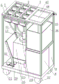
FIG. 1 is a schematic diagram of embodiment 1 of the present invention;
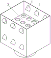
FIG. 2 is a schematic view of an instrument placement slot according to example 1 of the present invention;
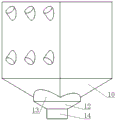
FIG. 3 is a schematic view showing the connection between the instrument placement slot and the transition slot according to embodiment 1 of the present invention;
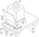
FIG. 4 is a schematic view of a base and a collecting container according to embodiment 1 of the present invention;
FIG. 5 is an enlarged view of a portion of FIG. 4;
FIG. 6 is a schematic view of a slide hole according to embodiment 1 of the present invention
FIG. 7 is a schematic diagram of a trigger switch according to embodiment 1 of the present invention;
FIG. 8 is an exploded view of the trigger switch according to embodiment 1 of the present invention;
FIG. 9 is an enlarged view of a portion of FIG. 1;
FIG. 10 is a schematic view of a reduction gear mechanism according to embodiment 1 of the present invention;
fig. 11 is a schematic diagram of the lap joint structure of embodiment 1 of the present invention.
In the figure: the placing table 1, the instrument placing tank 2, the filter screen 3, the flushing head 4, the sterilizing head 5, the sterilizing water pipe 6, the flushing water pipe 7, the water tank 8, the sterilizing tank 9, the collecting tank 10, the conveying pipe 11, the transition section 12, the upper connecting section 13, the lower connecting section 14, the collecting pipe 15, the collecting vessel 16, the lever 17, the sealing cover 18, the rotary seal 19, the base 20, the universal wheel 21, the directional wheel 22, the placing tank 23, the coaming 24, the fixed stopper 25, the movable stopper 26, the groove 27, the coaming section 28, the inclined plate section 29, the baffle 30, the slide hole 31, the mounting groove 32, the supporting spring 33, the inclined section 34, the horizontal section 35, the vertical section 36, the pedal 37, the vertical groove 38, the slide bar 39, the slide groove 40, the slide 41, the movable plate 42, the stopper 43, the stopper 44, the pull ring 45, the garbage can 46, the driving plate 47, the driven plate 48, the driving shaft 49, the driven shaft 50, the handle 51, the small sprocket 52, the large sprocket 53, the chain 54, the mounting box 55, the lower connecting groove 56, the upper connecting groove 57, the positioning gear 58, the ratchet 59, the ratchet 60, the gear 60, and the driven gear 61.
Detailed Description
Example 1
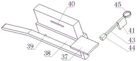
1-11, a tumor surgical instrument placement device comprises a placement table 1 which is horizontally arranged, wherein the placement table 1 comprises an instrument area and an auxiliary material area which is arranged behind the instrument area; the instrument area is uniformly distributed with instrument placing grooves 2, a filter screen 3 is arranged in each instrument placing groove 2, and the instrument placing grooves 2 are connected with an instrument cleaning mechanism; the auxiliary material area is of a groove-shaped structure, and the auxiliary material area is connected with an auxiliary material packaging mechanism.
As shown in fig. 2, the instrument placement groove 2 is of a hollow quadrangular prism structure with two open ends, and the instrument placement groove 2 is vertically arranged; the filter screen 3 all sets up in the middle part of apparatus standing groove 2, and filter screen 3 all level sets up and links firmly with the inner wall of standing groove all around. The instrument cleaning mechanism comprises a spray head connected to the side wall of the instrument placing groove 2; the bottom end of the spray head is positioned in the placing groove, and the top end of the spray head is positioned outside the placing groove and connected with the water pipe; twelve spray heads are arranged in each placing groove, and two groups of three opposite spray heads are arranged above and below the filter screen 3; the shower nozzle includes shower nozzle 4 and disinfection shower nozzle 5, is connected with disinfection water pipe 6 and flushing water pipe 7 on the standing groove outer wall, and shower nozzle 4 and disinfection shower nozzle 5 are respectively through flushing water pipe 7 and disinfection water pipe 6 connection water tank 8 and disinfection case 9, and the both ends of every group shower nozzle are shower nozzle 4, and the centre is disinfection shower nozzle 5. Water pumps are arranged in the water tank 8 and the disinfection tank 9 and are used for providing power; the two water pumps are connected with the controller, the controller is connected with the switch, and the controller is used for realizing automatic spraying of disinfectant for disinfection after flushing.
As shown in fig. 3, the instrument cleaning mechanism further comprises a collecting assembly connected with the bottom end of the placing groove; the collecting assembly comprises a collecting tank 10 connected with the bottom end of each placing tank, and each collecting tank 10 is of a quadrangular frustum pyramid structure with a large upper part and a small lower part; each collecting tank 10 is provided with an opening at the upper end and the lower end; the top of each collecting tank 10 is connected with a placing tank, and the bottom is connected with a conveying pipe 11. The lower part of each collecting tank 10 is connected with a vertical transition tank; the transition groove is a revolving body structure with openings at the upper end and the lower end; the transition groove comprises a transition section 12 in the middle, the transition section 12 is of a truncated cone-shaped structure with a large upper part and a small lower part, the top end of the transition section 12 is fixedly connected with a cylindrical upper connecting section 13, the top end of the upper connecting section 13 is fixedly connected with the outer wall of the lower part of the collecting groove 10, and the inner diameter of the upper connecting section 13 is larger than the diameter of an circumscribed circle at the bottom end of the collecting groove 10; the bottom of the transition section 12 is connected with a cylindrical lower connecting section 14, and the lower part of the lower connecting section 14 is connected with the top of the conveying pipe 11. Because the bottom of the transition groove is square, if the bottom of the direct connection conveying pipe 11 is provided with a plane, the waste liquid can not flow smoothly to form accumulated liquid, and therefore, the upper connecting section 13 is arranged to enable the waste liquid to enter the cylindrical pipe and then flow into the conveying pipe 11; the transition section 12 can change the upper connecting section 13 with a large diameter into the lower connecting section 14 with a small diameter, so that the conveying pipe 11 with a proper diameter can be conveniently connected, and the space utilization rate is improved. The conveying pipes 11 are all flexible pipes, one ends of all the conveying pipes 11 far away from the collecting tank 10 are commonly connected with a vertical collecting pipe 15, and the bottom of the collecting pipe 15 is connected with a collecting container.
As shown in fig. 4, the collecting container includes a collecting tub 16, and further includes a connection cover and a sealing cover 18 detachably connected to a top end opening of the collecting tub 16; the connecting cover and the sealing cover 18 are both in threaded connection with the collecting barrel 16, so that the sealing effect and the stability of connection are ensured; the center of the connecting cover is provided with a connecting hole coaxial with the connecting cover, and the connecting hole is rotationally connected with the bottom of the collecting pipe 15. A rotary seal 19 is connected between the collecting pipe 15 and the connecting hole.
The lower part of the placing table 1 is fixedly connected with a base 20 through a supporting rod, the base 20 is horizontally arranged, and a pair of universal wheels 21 and a pair of directional wheels 22 are connected below the base 20. The base 20 is provided with a mover including a receiving groove 23 matched with the collecting tub 16, and further includes a pair of universal wheels 21 and a pair of directional wheels 22 connected at the bottom end of the receiving groove 23.
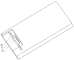
The base 20 is provided with an auxiliary structure matched with the containing groove 23; the auxiliary structure comprises a coaming 24 vertically arranged on the left, right and back sides of the containing groove 23 and a movable plate 42 arranged on the front side; the coaming plates 24 are fixedly connected with the base 20; the movable plate 42 is rotatably connected with the base 20 through a rotating shaft, and the rotating shaft is horizontally arranged; the coaming 24 is a short plate, the movable plate 42 is a long plate, and the width of the movable plate 42 is larger than the interval between the two orientation wheels 22; the movable plate 42 is provided with a fixed stopper 25 on one side (rear side) opposite to the coaming 24 and a movable stopper 26 on the other side (front side); the movable stopper 26 is connected with a trigger switch. The base 20 is provided with a groove 27 with the thickness consistent with that of the movable plate 42, the groove 27 is arranged at the front end of the base 20, the upper part and the front part are both openings, and the movable plate 42 is rotationally connected at the rear end of the groove 27; the movable plate 42 comprises a surrounding baffle section 28 connected with the rotating shaft, and also comprises an inclined plate section 29 arranged at one end of the surrounding baffle section 28 far away from the rotating shaft, wherein an included angle between the inclined plate section 29 and the surrounding baffle section 28 is an obtuse angle; when the enclosure section 28 is vertical, the sloping plate section 29 slopes forward from bottom to top; the enclosure section 28 plays a role of restricting the containing groove 23 when rotating to the vertical state; when the enclosing block 28 rotates to a horizontal state, one end of the inclined plate section 29 away from the enclosing block 28 is contacted with the ground, and the inclined plate section 29 forms a slope so that the shifter can conveniently move down the base 20. Baffle plates 30 perpendicular to the inclined plate section 29 and the surrounding baffle section 28 are fixedly connected to the left and right ends of the inclined plate section 29 and the surrounding baffle section 28, and the baffle plates 30 can be prevented from sliding down from the left and right sides of the movable plate 42 in the process of moving the shifter down the base 20. The fixed stopper 25 corresponds to the shutter 30, and restricts the backward rotation of the movable plate 42 by restricting the shutter 30, while the rear end of the recess 27 also restricts the backward rotation of the movable plate 42.
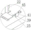
As shown in fig. 5-8, a vertical sliding hole 31 is formed in the base 20, a vertical groove 38 communicated with the sliding hole 31 is fixedly connected below the base 20, the bottom end of the vertical groove 38 is closed, and the top end of the vertical groove is communicated with the sliding hole 31; the movable stop block 26 is arranged in a sliding way in the sliding hole 31 and the vertical groove 38, and the bottom ends of the movable stop block 26 and the vertical groove 38 are connected with a supporting spring 33. The trigger switch comprises a lever 17, the left end of the lever 17 is rotationally connected with the base 20, the right end of the lever is connected with a pedal 37, and a supporting spring 33 is arranged below the pedal 37. The lever 17 comprises an inclined section 34 rotationally connected with the base 20, and further comprises a horizontal section 35 fixedly connected with the right end of the inclined section 34, a vertical section 36 is fixedly connected with the right end of the horizontal section 35, and a horizontal pedal 37 is fixedly connected with the top end of the vertical section 36; the bottom surface of recess 27 has seted up vertical mounting groove 32, and lever 17 sets up in mounting groove 32, and the left end is connected with mounting groove 32 rotation. The horizontal section 35 of the lever 17 is connected with a slide bar 39 perpendicular to the horizontal section, the lever 17 is arranged in the left-right direction, and the slide bar 39 is arranged in the front-back direction; the movable stopper 26 is provided with a chute 40 slidably connected to the slide rod 39, and the chute 40 is horizontally arranged in the left-right direction. The inclined section 34 of the lever 17 is for efficiently utilizing the height of the mounting groove 32, the left end of the inclined section 34 of the lever 17 is connected with the bottom of the mounting groove 32, the horizontal section 35 is arranged on the upper portion of the mounting groove 32, the vertical moving distance between the horizontal section 35 and the sliding rod 39 is increased as much as possible in the limited height of the mounting groove 32, and the vertical moving distance between the sliding chute 40 and the movable stop 26 is further increased, so that the stop can completely enter the sliding hole 31 when being pressed down by the sliding rod 39, and the stop is prevented from being propped against the bottom end of the movable plate 42 to interfere with the movable plate 42.
As shown in fig. 8, the trigger switch comprises a sliding seat 41 fixedly connected to the base 20, wherein a horizontal sliding hole 31 is formed in the sliding seat 41; a limiting rod 43 is connected in the sliding hole 31 in a sliding way, the limiting rod 43 is arranged below the pedal 37, and the sliding hole 31 and the limiting rod 43 are perpendicular to the lever 17; one end of the limiting rod 43, which is close to the lever 17, is connected with a limiting block 44, and the other end is connected with a pull ring 45.
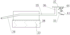
As shown in fig. 8-11, the bottom end of the auxiliary material area is provided with a pair of rotating plates, each rotating plate is rotationally connected with the placing table 1 through a connecting shaft and a shaft sleeve, and the connecting shafts are horizontally arranged in the front-back direction; one end of each rotating plate, which is adjacent to the other end of each rotating plate, is provided with a lap joint structure; the auxiliary material packaging mechanism comprises a garbage can 46 arranged below the auxiliary material area, and a garbage bag is arranged in the garbage can 46; the base 20 is provided with a limit groove matched with the garbage can 46. The disinfection case 9 and the water tank 8 are fixedly connected to the base 20, the limiting groove is fixedly formed in the top ends of the disinfection case 9 and the water tank 8, and the garbage bin 46 is arranged in the limiting groove.
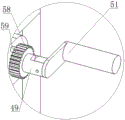
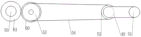
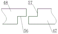
The rotating plate comprises a driving plate 47 and a driven plate 48, a connecting shaft on the driving plate 47 is a driving shaft 49, and a connecting shaft on the driven plate 48 is a driven shaft 50; the driving shaft 49 is connected with a handle 51, and the handle 51 is arranged to rotate along the axial direction of the driving shaft 49, so that the handle 51 can be folded and unfolded; a speed reduction transmission mechanism is connected between the two rotating plates. The speed reduction transmission mechanism comprises a small sprocket 52 which is coaxial with the driving shaft 49 and fixedly connected with the driving shaft 49, and also comprises a driven gear 61 which is coaxial with the driven shaft 50 and fixedly connected with the driven shaft 50, the driven gear 61 is in meshed connection with a turning gear 60, the turning gear 60 is fixedly connected with a large sprocket 53 which is coaxial with the turning gear 60, the small sprocket 52 and the large sprocket 53 are connected with a chain 54, the transmission ratio of the driven gear 61 and the small sprocket 52 is smaller than 1, and the driven gear 61 and the driven shaft 50 rotate slower than the small sprocket and the driving shaft 49; the driving shaft 49 and the driven shaft 50 are connected with an installation box 55, the installation box 55 is rotationally connected with the driving shaft 49 and the driven shaft 50, and the small sprocket 52, the turning gear 60, the driven gear 61, the large sprocket 53 and the chain 54 are arranged in the installation box 55, and the turning gear 60 and the large sprocket 53 are rotationally connected with the installation box 55. The overlap joint structure includes the lower spread groove 56 of seting up in driven plate 48 bottom, still includes the last spread groove 57 of seting up on driving plate 47 top, and the right-hand member of driving plate 47 sets up in last spread groove 57, and the left end setting of driven plate 48 is in lower spread groove 56. The placing table 1 is also provided with a ratchet mechanism matched with the driving shaft 49, the ratchet mechanism comprises a positioning gear 58 fixedly connected and coaxial with the driving shaft 49, and a ratchet 59 rotatably connected on the mounting box 55, and the ratchet 59 can rotate into a tooth slot of the positioning gear 58.
Example 2
A tumor surgical instrument placement device adopting the following method, comprising the following steps:
step 1, placing the used tumor surgical instrument into an instrument accommodating groove 23, and placing the used auxiliary materials into an auxiliary material area; counting auxiliary materials and surgical instruments.
Step 2, cleaning surgical instruments; the switch is turned on, the controller controls the water pump in the water tank 8 to start, and then the cleaning spray heads on the upper, lower, left and right are used for flushing the surgical instruments; after the flushing is finished, a water pump in the disinfection box 9 is started, and the disinfecting liquid disinfects the flushed surgical instruments. During flushing and disinfection, the waste liquid passes downwards from the instrument receiving channel 23 through the collecting channel 10, the transition channel, the transfer tube 11 and the collecting tube 15 into the collecting vessel 16.
Step 4, packaging auxiliary materials; putting the garbage can 46 into a limiting groove, then removing the ratchet wheel from the tooth groove, rotating the handle 51 anticlockwise, driving the driving shaft 49 and the driving plate 47 to rotate downwards by the handle 51, driving the driven shaft 50 and the driven plate 48 to rotate downwards by the driving shaft 49 through the small chain wheel 52, the chain 54, the large chain wheel 53, the turning gear 60 and the driven gear 61, then sliding the auxiliary materials from the driving plate 47 and the driven plate 48 into the garbage can 46, taking out the garbage bag and packing the auxiliary materials; finally, after the driving plate 47 and the driven plate 48 are cleaned, the handle 51 and the ratchet 59 are reset in sequence, the handle 51 is rotated in the front-rear direction along the axial direction of the driving shaft 49, and the handle 51 is retracted.
Claims (10)
1. The tumor surgical instrument placement device comprises a placement table, and is characterized in that the placement table comprises an instrument area and an auxiliary material area; the device area is uniformly provided with device placing grooves, a filter screen is arranged in the device placing grooves, and the device placing grooves are connected with a device cleaning mechanism; the auxiliary material area is of a groove-shaped structure, and the auxiliary material area is connected with an auxiliary material packaging mechanism.
2. The oncological surgical instrument placement device according to claim 1, wherein the screen is disposed in a middle portion of the instrument placement slot; the instrument cleaning mechanism comprises spray heads connected to the side walls of the instrument placing grooves, at least two spray heads are arranged, the spray heads are respectively arranged above and below the filter screen, and each spray head is arranged towards the filter screen.
3. The oncological surgical instrument placement device according to claim 2, wherein the instrument cleaning mechanism further comprises a collection assembly connected to a bottom end of the placement tank; the collecting assembly comprises a collecting tank connected with the bottom end of each placing tank, and each collecting tank is of a structure with a large upper part and a small lower part; each collecting tank is provided with an opening at the upper end and the lower end; the top end of each collecting tank is connected with the placing tank, and the bottom end of each collecting tank is connected with the conveying pipe; all the ends of the conveying pipes far away from the collecting tank are commonly connected with a collecting pipe, and the collecting pipe is connected with a collecting container.
4. The oncological surgical instrument placement device according to claim 3, wherein the collection container comprises a collection tub, and further comprising a connection cap and a sealing cap that mate with the collection tub; the connecting cover is provided with a connecting hole, and the connecting hole is rotationally connected with the collecting pipe and axially fixedly connected with the collecting pipe.
5. The oncological surgical instrument placement device according to claim 4, wherein a base is connected below the placement table, a mover is provided on the base, the mover includes a receiving groove matched with the collection tub, and further includes a pair of universal wheels and a pair of directional wheels connected at a bottom end of the receiving groove.
6. The tumor surgical instrument placement device according to claim 5, wherein the base is provided with an auxiliary structure matched with the accommodating groove; the auxiliary structure comprises coamings vertically arranged on three sides of the containing groove and a movable plate arranged on the other side; the coaming plates are fixedly connected with the base; a rotating shaft is connected between the movable plate and the base, and the rotating shaft is horizontally arranged; a fixed stop block is arranged on one side of the movable plate, which is opposite to the coaming, and a movable stop block is arranged on the other side of the movable plate; the movable stop block is connected with a trigger switch.
7. The tumor surgical instrument placement device according to claim 6, wherein the trigger switch comprises a lever, one end of the lever is rotatably connected with the base, the other end of the lever is connected with a pedal, and a supporting spring is arranged below the pedal; the middle part of lever is connected with the slide bar, set up the spout with slide bar sliding connection on the movable stop, the spout level sets up.
8. The tumor surgical instrument placement device according to claim 7, wherein the trigger switch comprises a slide seat fixedly connected to the base, and a slide hole is formed in the slide seat; the sliding hole is in sliding connection with a limiting rod, the limiting rod is arranged below the pedal, and the sliding hole and the limiting rod are perpendicular to the lever; one end of the limiting rod, which is close to the lever, is connected with a limiting block, and the other end of the limiting rod is connected with a pull ring.
9. The oncological surgical instrument placement device according to any one of claims 1-8, wherein the bottom end of the auxiliary material region is provided with a pair of rotating plates, each of which is rotatably connected with the placement table; the auxiliary material packaging mechanism comprises a garbage bin arranged below the auxiliary material area, and a garbage bag is arranged in the garbage bin; the base is provided with a limit groove matched with the garbage can.
10. The oncological surgical instrument placement device according to claim 9, wherein a handle is connected to one of the rotating plates, and a reduction transmission mechanism is connected between the two rotating plates.
Priority Applications (1)
| Application Number | Priority Date | Filing Date | Title |
|---|---|---|---|
| CN202310304043.8A CN116158865A (en) | 2023-03-27 | 2023-03-27 | Tumor surgical instrument placement device |
Applications Claiming Priority (1)
| Application Number | Priority Date | Filing Date | Title |
|---|---|---|---|
| CN202310304043.8A CN116158865A (en) | 2023-03-27 | 2023-03-27 | Tumor surgical instrument placement device |
Publications (1)
| Publication Number | Publication Date |
|---|---|
| CN116158865A true CN116158865A (en) | 2023-05-26 |
Family
ID=86411556
Family Applications (1)
| Application Number | Title | Priority Date | Filing Date |
|---|---|---|---|
| CN202310304043.8A Pending CN116158865A (en) | 2023-03-27 | 2023-03-27 | Tumor surgical instrument placement device |
Country Status (1)
| Country | Link |
|---|---|
| CN (1) | CN116158865A (en) |
-
2023
- 2023-03-27 CN CN202310304043.8A patent/CN116158865A/en active Pending
Similar Documents
| Publication | Publication Date | Title |
|---|---|---|
| JP2021030201A (en) | Appliance for maintaining cleanliness of keyboard | |
| CN109867250B (en) | Full-automatic filling system of bottled water | |
| CN205307436U (en) | Internal medicine apparatus degassing unit | |
| EP2011580A2 (en) | Blending Device | |
| CN107693932A (en) | A kind of sterile automatic dipping liquid device of cotton swab | |
| CN109649807B (en) | Aseptic liquid separating device for cotton swab dipping liquid | |
| CN206550060U (en) | A kind of medical device cleaning sterilizing device | |
| CN108379622A (en) | A kind of special or delicate procedure sterilization of instruments equipment of each section of operation | |
| CN116158865A (en) | Tumor surgical instrument placement device | |
| CN212093434U (en) | Industrial solid waste cleaning and disinfecting device | |
| CN113058057A (en) | Universal sterilizing device for nursing | |
| CN111729112A (en) | Wrapping bag sterilizing equipment that fine bread crumbs were used | |
| CN212597436U (en) | Cleaning and sterilizing device for medical instruments of obstetrics and gynecology department | |
| CN217148678U (en) | Clinical medicine inspection waste liquid treatment device | |
| CN108713959A (en) | A kind of suction pipe | |
| CN214969519U (en) | Sanitation and disinfection device for preventive medicine | |
| CN214718846U (en) | Automatic decontamination equipment for medical instrument | |
| CN205322051U (en) | Self -service juice extractor | |
| CN204072850U (en) | A kind of hygienic article sterilizing equipment decontaminating apparatus | |
| CN113058058A (en) | Universal disinfection method for nursing | |
| CN113928757A (en) | Recovery equipment for automatic disinfection of medical waste | |
| CN116196186B (en) | Debridement device for general surgery department | |
| CN112666343A (en) | Needle plate for newly screening blood sheets in neonatal disease screening | |
| CN219071410U (en) | Bus disinfection equipment | |
| CN219172855U (en) | Sterilizing cabinet for tea packaging |
Legal Events
| Date | Code | Title | Description |
|---|---|---|---|
| PB01 | Publication | ||
| PB01 | Publication | ||
| SE01 | Entry into force of request for substantive examination | ||
| SE01 | Entry into force of request for substantive examination |