CN116140472A - Crusher hammer production equipment and production process thereof - Google Patents
Crusher hammer production equipment and production process thereof Download PDFInfo
- Publication number
- CN116140472A CN116140472A CN202310174106.2A CN202310174106A CN116140472A CN 116140472 A CN116140472 A CN 116140472A CN 202310174106 A CN202310174106 A CN 202310174106A CN 116140472 A CN116140472 A CN 116140472A
- Authority
- CN
- China
- Prior art keywords
- hammer
- rod
- ejector rod
- adsorption
- liquid
- Prior art date
- Legal status (The legal status is an assumption and is not a legal conclusion. Google has not performed a legal analysis and makes no representation as to the accuracy of the status listed.)
- Pending
Links
Images

Classifications
-
- B—PERFORMING OPERATIONS; TRANSPORTING
- B21—MECHANICAL METAL-WORKING WITHOUT ESSENTIALLY REMOVING MATERIAL; PUNCHING METAL
- B21D—WORKING OR PROCESSING OF SHEET METAL OR METAL TUBES, RODS OR PROFILES WITHOUT ESSENTIALLY REMOVING MATERIAL; PUNCHING METAL
- B21D37/00—Tools as parts of machines covered by this subclass
- B21D37/10—Die sets; Pillar guides
-
- B—PERFORMING OPERATIONS; TRANSPORTING
- B08—CLEANING
- B08B—CLEANING IN GENERAL; PREVENTION OF FOULING IN GENERAL
- B08B13/00—Accessories or details of general applicability for machines or apparatus for cleaning
-
- B—PERFORMING OPERATIONS; TRANSPORTING
- B08—CLEANING
- B08B—CLEANING IN GENERAL; PREVENTION OF FOULING IN GENERAL
- B08B9/00—Cleaning hollow articles by methods or apparatus specially adapted thereto
- B08B9/08—Cleaning containers, e.g. tanks
- B08B9/087—Cleaning containers, e.g. tanks by methods involving the use of tools, e.g. brushes, scrapers
-
- B—PERFORMING OPERATIONS; TRANSPORTING
- B08—CLEANING
- B08B—CLEANING IN GENERAL; PREVENTION OF FOULING IN GENERAL
- B08B9/00—Cleaning hollow articles by methods or apparatus specially adapted thereto
- B08B9/08—Cleaning containers, e.g. tanks
- B08B9/093—Cleaning containers, e.g. tanks by the force of jets or sprays
Landscapes
- Engineering & Computer Science (AREA)
- Mechanical Engineering (AREA)
- Perforating, Stamping-Out Or Severing By Means Other Than Cutting (AREA)
Abstract
The invention discloses crusher hammer production equipment, which comprises a frame, an upper die and a lower die, wherein an upward jacking ejector rod is arranged in the lower die, and a plurality of spray heads for spraying liquid are slidably arranged in the ejector rod; a pulling plate is arranged on the ejector rod and is connected with an adsorption plate through a pull rope; the upper die is provided with an adsorption rod, and the adsorption rod is provided with an electromagnet capable of driving the adsorption plate to lift upwards; the invention provides hammer production equipment capable of blowing a blank during hammer stamping, ejecting a formed hammer during forming and stamping, cleaning the die cavity without dead angle, and simultaneously carrying out rapid reflux collection on the cleaned liquid, thereby greatly improving the production efficiency of the hammer and the product quality of the hammer.
Description
Technical Field
The invention relates to the technical field of hammer production equipment, in particular to crusher hammer production equipment and a crusher hammer production process.
Background
The hammer head is a wear-resistant part of the crusher, is usually used for hammering and crushing materials entering the crusher, so that the hammer head is made of wear-resistant materials, the existing hammer head is produced in a hot press forming mode, the hammer head has higher wear resistance, a lower die cavity is required to be cleaned and lubricated after forging, and the existing punch press has the following defects and disadvantages when forging the hammer head:
after forging, the inner cavity of the lower die is difficult to clean, dead corners which are difficult to clean are formed, and high-pressure flushing and cleaning are needed to be carried out on the dead corners manually, so that time and labor are wasted;
during forging, the heated blank is placed on the lower die, so that scraps and impurities are generated by oxidation in the air, and the surface quality after stamping is affected.
Disclosure of Invention
Aiming at the defects in the prior art, the invention provides a crusher hammer production device and a production process thereof.
In order to solve the technical problems, the invention is solved by the following technical scheme: the crusher hammer production equipment comprises a frame, an upper die and a lower die.
In the above scheme, preferably, an upward jacking ejector rod is arranged in the lower die, and a plurality of spray heads for spraying liquid are slidably arranged in the ejector rod;
a pulling plate is arranged on the ejector rod and is connected with an adsorption plate through a pull rope;
the upper die is provided with an adsorption rod, and the adsorption rod is provided with an electromagnet capable of driving the adsorption plate to lift upwards;
the spray head is connected with an inclined block, a driving sleeve matched with the inclined block is fixedly arranged on the rack, a movable cavity for sliding of the inclined block is arranged in the ejector rod, and a first spring is arranged between the inclined block and the ejector rod.
In the above scheme, preferably, a second spring is arranged between the pull plate and the frame.
In the above scheme, preferably, the frame is provided with a cylinder body for providing liquid for the spray head, a piston is arranged in the cylinder body, the cylinder body comprises a liquid supply cavity and a gas supply cavity, the liquid supply cavity is connected with the spray head, and the piston is connected with the adsorption rod through a piston rod.
In the above scheme, preferably, the liquid supply cavity is connected with a liquid storage tank.
In the above scheme, preferably, the upper die is provided with a plurality of air ejector pipes for blowing the blank when the upper die slides downwards, and the air supply cavity is connected with the air ejector pipes through a first one-way valve.
In the above scheme, preferably, be equipped with a plurality of return holes on the ejector pin, the return hole is connected with the rose box, the rose box passes through the second check valve and links to each other with the air feed chamber, go up the mould and make the air feed chamber suck the return hole through the second check valve when promoting.
In the above scheme, preferably, the adsorption rod is provided with a connecting plate connected with the piston rod, the rack is provided with a first button matched with the connecting plate, and the first button is connected with the electromagnetic iron.
In the above scheme, preferably, the frame is provided with a plurality of support rods propped against the pull plate.
In the above scheme, preferably, the inclined plane is arranged on the inclined block, and the inclined plane on the inclined block is matched with the driving sleeve to realize the transverse sliding of the spray head when the ejector rod slides up and down.
In the above scheme, preferably, the production process of the crusher hammer production equipment comprises the following steps:
s1: placing the hammer head blank on a lower die cavity, at the moment, adapting the upper end of the ejector rod to the surface of the lower die cavity, and then starting the punch;
s2: the upper die slides downwards to enable the piston to slide downwards, the air supply cavity is extruded to discharge high-pressure air through the first one-way valve and the air injection pipe, so that the upper die sweeps the surface of the blank in the sliding process;
s3: while S2 is carried out, the liquid supply cavity is pumped to pump the liquid in the liquid storage tank into the liquid supply cavity;
s4: the upper die slides downwards to the lowest position and is matched with the lower die to enable a hammer blank to be pressed into a hammer, simultaneously, an electromagnet on an adsorption rod adsorbs an adsorption plate, and then the upper die is lifted upwards;
s5: the adsorption plate is adsorbed and lifted, and then the pull plate is driven by the pull rope to lift upwards, so that the ejector rod is lifted upwards, the upper end of the ejector rod ejects the hammer head out of the die cavity, meanwhile, the inclined block on the spray head in the ejector rod is separated from the matching with the driving sleeve, the first spring pulls the inclined block to enable the spray head to be arranged outside the ejector rod, and meanwhile, the piston lifts upwards to extrude the liquid supply cavity to enable liquid to be sprayed out through the spray head, and the lower die cavity is cleaned and lubricated;
s6: s5, at the same time, the cleaned liquid flows back through a backflow hole on the ejector rod, when the piston is lifted upwards, the air supply cavity generates negative pressure, the backflow hole is sucked through the second one-way valve, and the liquid rapidly enters the filter box through the backflow hole;
s7: when the upper die rises to the topmost position, the formed hammer is thoroughly ejected, meanwhile, the first button triggers the electromagnet to cut off power to enable the adsorption plate to be separated from adsorption, the ejector rod resets under the action of the second spring, and the ejector rod drives the oblique block to transversely slide into the ejector rod through guide extrusion of the driving sleeve in the resetting process.
The beneficial effects of the invention are as follows: the invention provides the hammer production equipment which can sweep a blank during the stamping of the hammer, eject the formed hammer when the forming stamping is finished, clean the die cavity without dead angles, and simultaneously can quickly reflux and collect the cleaned liquid, thereby greatly improving the production efficiency of the hammer and the product quality of the hammer.
Drawings
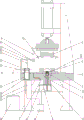
Fig. 1 is a schematic diagram of a front view structure of the present invention.
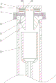
Fig. 2 is a schematic view of a partial enlarged structure of the present invention at a.
FIG. 3 is a schematic view of the drive sleeve of the present invention disengaged from the swash block.
Description of the embodiments
The invention is described in further detail below with reference to the attached drawings and detailed description: referring to fig. 1-3, the crusher hammer production equipment comprises a frame 1, an upper die 2 and a lower die 3, wherein the upper die 2 is slidably arranged on the frame 1 through a driving cylinder, the lower die 3 is fixedly arranged on the frame 1 and is positioned below the upper die 2, the crusher hammer production equipment is an existing structure of a punching machine, and is not repeated herein, a die cavity matched with a hammer head is arranged on the lower die 3, and when the upper die 2 is matched with the lower die 3, a blank placed on the lower die 3 can be formed into the hammer head.
The lower die 3 is internally provided with a push rod 4 penetrating through the frame 1, the upper end of the push rod 4 is provided with a joint surface matched with the die cavity of the lower die 3, namely, the push rod 4 is slidably arranged on the lower die 3 and the frame 1, the lower end of the push rod 4 is provided with a pull plate 6, the frame 1 is provided with a support rod 43 propped against the pull plate 6, and the support rods 43 are preferably arranged on two sides of the push rod 4.
When the lower end face of the pull plate 6 is attached to the upper end of the supporting rod 43, the upper end of the ejector rod 4 is combined with the inner die surface of the die cavity of the lower die 3 to form an integral punching cavity, namely, a blank is placed in the lower die 3 at this time and then can be punched through the upper die 2 to form a complete hammer.
The utility model discloses a die, including lower mould 3 die cavity, including the arm-tie, the arm-tie 6 is connected with adsorption plate 8 through stay cord 7, stay cord 7 wears to establish behind frame 1 at frame 1 terminal surface and adsorption plate 8 fixed connection, adsorption plate 8 is preferably iron plate, has stronger ferromagnetism, for ejecting the tup after making the punching press through ejector pin 4, be equipped with adsorption rod 9 on the upper mould 2, adsorption rod 9 lower extreme is equipped with the electro-magnet 10 that can inhale with adsorption plate 8, when upper mould 2 gliding to the minimum, the electro-magnet 10 on the adsorption rod 9 can inhale with adsorption plate 8, and adsorption plate 8 is adsorbed by electro-magnet 10 when punching press shaping, and then upper mould 2 accomplishes the punching press and upwards slides, and electro-magnet 10 drives adsorption plate 8 upwards to slide and upwards moves arm-tie 6 this moment to make ejector pin 4 upwards push out, with the tup in the lower mould 3 die cavity ejecting.
The second spring 15 is arranged between the pull plate 6 and the frame 1, the second spring 15 is sleeved on the push rod 4, two ends of the second spring respectively lean against the upper end faces of the frame 1 and the pull plate 6, as shown in fig. 1, the push rod 4 is a hollow pipe with the upper end blocked and the lower end communicated, a driving sleeve 12 matched with an inner hole of the push rod 4 is fixedly arranged on the frame 1, and the push rod 4 can slide on the driving sleeve 12 when moving up and down.
The ejector rod 4 is internally provided with a plurality of spray heads 5 for spraying liquid, the liquid is preferably lubricating liquid, the spray heads 5 are preferably uniformly provided with 2-6 groups around the circumference of the ejector rod 4, the spray heads 5 are preferably universal spray heads, namely, the joint of the spray heads 5 and a pipe fitting is a universal adjusting head, so that the spraying angle of the spray heads 5 can be adjusted, as shown in fig. 2, the spray heads 5 are transversely arranged at the upper end of the ejector rod 4 in a sliding manner, one side of the spray heads 5 close to the center of the ejector rod 4 is provided with an inclined block 11, the inclined block 11 is provided with an inclined surface 51, the inclined surface 51 inclines towards one side close to the center of the ejector rod 4 from top to bottom, the lower part of the spray heads 5 close to one side of the center of the ejector rod 4 is fixedly provided with the inclined block 11, the upper part is fixedly provided with a guide plate 101, a movable cavity 13 for the inclined block 11 and the guide plate 101 to move is arranged in the ejector rod 4, a first spring 14 is arranged between the guide plate 101 and the inner cavity wall of the movable cavity 13 of the ejector rod 4, and the first spring 14 is preferably a tension spring, and a guide rod 102 matched with the guide plate 101 is fixedly arranged on the inner cavity wall of the movable cavity 13, namely, the spray heads 5 can slide on the guide rod 101 or the guide plate 102 to move outside the ejector rod 5 to the movable cavity 13 through the guide plate 101.
At first, the inner hole of the driving sleeve 12 is attached to the straight wall of the inclined block 11 far away from the center of the ejector rod 4, when the ejector rod 4 slides upwards, namely, the ejector rod 4 ejects the formed hammer head upwards, the inner hole of the driving sleeve 12 is separated from contact with the inclined block 11, and at the moment, the inclined block 11 drives the spray head 5 under the tensile force of the first spring 14 to enable the spray head 5 to slide to the outer side of the ejector rod 4, so that the spray head 5 sprays and washes corners in a die cavity.
The spray head is characterized in that a cylinder 21 for providing liquid for the spray head 5 is arranged on the frame 1, a piston 22 is arranged in the cylinder 21, the cylinder 21 is divided into a liquid supply cavity 23 and a gas supply cavity 24 by the piston 22, the liquid supply cavity 23 is arranged above the piston 22, the gas supply cavity 24 is arranged below the piston 22, a piston rod 25 is fixedly arranged on the upper end surface of the piston 22, and the piston rod 25 is fixedly connected with the adsorption rod 9 through a connecting plate 41 after penetrating the cylinder 21 upwards, namely, the piston 22 can be driven to synchronously rise or slide downwards when the adsorption rod 9 rises or slides downwards.
The liquid supply cavity 23 is connected with the spray head 5, a one-way valve from the liquid supply cavity 23 to the spray head 5 is arranged between the liquid supply cavity 23 and the spray head 5, the liquid supply cavity 23 is connected with a liquid storage tank 26, a one-way valve from the liquid storage tank 26 to the liquid supply cavity 23 is arranged between the liquid storage tank 26 and the liquid supply cavity 23, namely, when the piston 22 slides downwards, the liquid supply cavity 23 is subjected to negative pressure to suck liquid in the liquid storage tank 26, and when the piston 22 slides upwards, the liquid supply cavity 23 is extruded, and the liquid in the liquid supply cavity 23 is sprayed out through the spray head 5.
The two sides of the upper die 2 are provided with a plurality of air ejector pipes 31 for blowing the surface of the blank when the upper die 2 slides downwards, the air supply cavity 24 is connected with the air ejector pipes 31 through a first one-way valve 32, the flow direction of the first one-way valve 32 is from the air supply cavity 24 to the air ejector pipes 31, namely when the upper die 2 slides downwards and drives the piston 22 to slide downwards through the adsorption rod 9 to squeeze the air supply cavity 24, the air supply cavity 24 blows out pressure air through the air ejector pipes 31 to blow the surface of the blank.
The ejector rod 4 is provided with a plurality of backflow holes 33 on the outer wall, the backflow holes 33 are communicated with the inner cavity of the ejector rod 4, the backflow holes 33 are arranged below the spray head 5, the pull plate 6 is provided with liquid discharge holes connected with the inner cavity of the ejector rod 4, namely, after the ejector rod 4 is ejected out, liquid ejected by the spray head 5 can flow back and be collected through the backflow holes 33 on the ejector rod 4 and is discharged through the liquid discharge holes, the liquid discharge holes are connected with a filter box 34, the filter box 34 is connected with the air supply cavity 24 through a second one-way valve 35, the second one-way valve 35 is used for enabling the flow direction to flow to the air supply cavity 24 from the filter box 34, when the upper die 2 is lifted, the adsorption rod 9 is lifted to drive the piston 22 to slide upwards, so that negative pressure is generated in the air supply cavity 24, and at the moment, the air supply cavity 24 sucks the backflow holes 33 through the filter box 34, and filters the recovered liquid at the same time.
Be equipped with on the frame 1 with connecting plate 41 matched with first button 42, first button 42 is connected with the electro-magnet 10 electricity, and promptly initially, when last mould 2 is located the uppermost, first button 42 cooperates with connecting plate 41, and first button 42 is triggered this moment, makes electro-magnet 10 outage, and when last mould 2 gliding, first button 42 breaks away from the contact with connecting plate 41, and electro-magnet 10 is energized this moment, and when last mould 2 gliding to the minimum, electro-magnet 10 adsorbs adsorption plate 8, drives adsorption plate 8 after last mould 2 punching press is accomplished and promotes simultaneously messenger's ejector pin 4 later, washs lower mould 3 die cavity when ejecting the tup after will punching press.
The production process of the crusher hammer production equipment comprises the following steps:
s1: placing the hammer head blank on a die cavity of the lower die 3, at the moment, adapting the upper end of the ejector rod 4 to the surface of the die cavity of the lower die 3, and then starting a punch;
s2: the upper die 2 slides downwards, the upper die 2 drives the adsorption rod 9 and the connecting plate 41 to slide downwards synchronously, so that the piston 22 slides downwards, the cavity of the air supply cavity 24 is extruded to discharge high-pressure air through the air injection pipe 31 by the first one-way valve 32, and the upper die 2 sweeps the surface of a blank in the sliding process;
s3: while S2 proceeds, the piston 22 slides down to generate negative pressure in the liquid supply chamber 23, and the liquid supply chamber 23 is sucked to suck the liquid in the liquid storage tank 26 into the liquid supply chamber 23;
s4: the upper die 2 slides downwards to the lowest position and is matched with the lower die 3 to press a hammer blank into a hammer, meanwhile, an electromagnet 10 on an adsorption rod 9 adsorbs an adsorption plate 8, and then the upper die 2 is lifted upwards;
s5: the adsorption plate 8 is adsorbed and lifted, the pulling plate 6 is driven to lift upwards through the pull rope 7, so that the ejector rod 4 is lifted upwards, the upper end of the ejector rod 4 ejects a hammer head from a die cavity, meanwhile, the inclined block 11 on the spray head 5 in the ejector rod 4 is separated from the matching with the driving sleeve 12, the first spring 14 pulls the inclined block 11 to enable the spray head 5 to be arranged outside the ejector rod 4, meanwhile, the piston 22 lifts upwards to extrude the liquid supply cavity 23 to enable liquid to be sprayed out through the spray head 5, liquid spraying is continuously carried out on one side of the ejector rod 4 in the lifting process, and dead angle-free cleaning and lubrication are carried out on the die cavity of the lower die 3;
s6: at the same time of S5, the cleaned liquid flows back through the backflow hole 33 on the ejector rod 4, when the piston 22 is lifted upwards, the air supply cavity 24 generates negative pressure and pumps the backflow hole 33 through the second one-way valve 35, so that the liquid rapidly enters the filter box 34 through the backflow hole 33;
s7: when the upper die 2 is lifted to the topmost position, the formed hammer is thoroughly ejected, meanwhile, the first button 42 triggers the electromagnet 10 to be powered off to enable the adsorption plate 8 to be separated from adsorption, the ejector rod 4 is reset under the action of the second spring 15, and the ejector rod 4 is guided and extruded by the inclined block 11 through the driving sleeve 12 in the resetting process to enable the spray head 5 to transversely slide into the ejector rod 4.
The above embodiments are only for illustrating the technical solution of the present invention, and are not limiting; although the invention has been described in detail with reference to the foregoing embodiments, it will be understood by those of ordinary skill in the art that: the technical scheme described in the foregoing embodiments can be modified or some technical features thereof can be replaced by equivalents; such modifications and substitutions do not depart from the spirit and scope of the technical solutions of the embodiments of the present invention.
Claims (10)
1. Breaker hammer production facility, including frame (1), go up mould (2) and lower mould (3), its characterized in that: an upward jacking ejector rod (4) is arranged in the lower die (3), and a plurality of spray heads (5) for spraying liquid are arranged in the ejector rod (4) in a sliding manner;
a pulling plate (6) is arranged on the ejector rod (4), and the pulling plate (6) is connected with an adsorption plate (8) through a pull rope (7);
an adsorption rod (9) is arranged on the upper die (2), and an electromagnet (10) capable of driving the adsorption plate (8) to lift upwards is arranged on the adsorption rod (9);
the shower nozzle (5) is connected with sloping block (11), set firmly on frame (1) with sloping block (11) matched with driving sleeve (12), be equipped with in ejector pin (4) and supply sloping block (11) gliding movable chamber (13), be equipped with first spring (14) between sloping block (11) and ejector pin (4).
2. The breaker head production apparatus of claim 1 wherein: a second spring (15) is arranged between the pulling plate (6) and the frame (1).
3. The breaker head production apparatus of claim 1 wherein: the spray head is characterized in that a cylinder body (21) for providing liquid for the spray head (5) is arranged on the frame (1), a piston (22) is arranged in the cylinder body (21), the cylinder body (21) comprises a liquid supply cavity (23) and a gas supply cavity (24), the liquid supply cavity (23) is connected with the spray head (5), and the piston (22) is connected with the adsorption rod (9) through a piston rod (25).
4. A crusher hammer production device according to claim 3, characterized by: the liquid supply cavity (23) is connected with a liquid storage tank (26).
5. The crusher hammer production device of claim 4, wherein: the upper die (2) is provided with a plurality of air ejector pipes (31) for blowing the blank when the upper die (2) slides downwards, and the air supply cavity (24) is connected with the air ejector pipes (31) through a first one-way valve (32).
6. The breaker head apparatus of claim 5 wherein: the ejector rod (4) is provided with a plurality of backflow holes (33), the backflow holes (33) are connected with a filter box (34), the filter box (34) is connected with the air supply cavity (24) through a second one-way valve (35), and the upper die (2) enables the air supply cavity (24) to suck the backflow holes (33) through the second one-way valve (35) when being lifted.
7. A crusher hammer production device according to claim 3, characterized by: the adsorption rod (9) is provided with a connecting plate (41) connected with the piston rod (25), the frame (1) is provided with a first button (42) matched with the connecting plate (41), and the first button (42) is electrically connected with the electromagnet (10).
8. The breaker head production apparatus of claim 1 wherein: the frame (1) is provided with a plurality of support rods (43) propped against the pull plate (6).
9. The breaker head production apparatus of claim 1 wherein: the inclined block (11) is provided with an inclined surface (51), and the inclined surface (51) on the inclined block (11) is matched with the driving sleeve (12) to realize the transverse sliding of the spray head (5) when the ejector rod (4) slides up and down.
10. A process for the production of a crusher hammer head production device according to any one of the preceding claims, characterized by: the process comprises the following steps:
s1: placing the hammer head blank on a die cavity of a lower die (3), at the moment, adapting the upper end of a push rod (4) to the surface of the die cavity of the lower die (3), and then starting a punch;
s2: the upper die (2) slides downwards to enable the piston (22) to slide downwards, the cavity of the air supply cavity (24) is extruded to discharge high-pressure air through the air injection pipe (31) through the first one-way valve (32), and the upper die (2) sweeps the surface of the blank in the sliding process;
s3: while S2 is performed, the liquid supply cavity (23) is sucked to suck the liquid in the liquid storage tank (26) into the liquid supply cavity (23);
s4: the upper die (2) slides downwards to the lowest position and is matched with the lower die (3) to enable a hammer blank to be pressed into a hammer, meanwhile, an electromagnet (10) on an adsorption rod (9) adsorbs an adsorption plate (8), and then the upper die (2) is lifted upwards;
s5: the adsorption plate (8) is adsorbed and lifted, the pull plate (6) is driven to lift upwards through the pull rope (7), so that the ejector rod (4) is lifted upwards, the upper end of the ejector rod (4) ejects a hammer head out of a die cavity, meanwhile, the inclined block (11) on the spray head (5) in the ejector rod (4) is separated from the matching with the driving sleeve (12), the first spring (14) pulls the inclined block (11) to enable the spray head (5) to be arranged outside the ejector rod (4), and meanwhile, the piston (22) lifts upwards to extrude the liquid supply cavity (23) to enable liquid to be sprayed out through the spray head (5), and the die cavity of the lower die (3) is cleaned and lubricated;
s6: at the same time of S5, the cleaned liquid flows back through a backflow hole (33) on the ejector rod (4), when the piston (22) is lifted upwards, the air supply cavity (24) generates negative pressure, the backflow hole (33) is sucked through the second one-way valve (35), and the liquid rapidly enters the filter box (34) through the backflow hole (33);
s7: when the upper die (2) rises to the topmost position, the formed hammer is thoroughly ejected, meanwhile, the first button (42) triggers the electromagnet (10) to cut off power to enable the adsorption plate (8) to be separated from adsorption, the ejector rod (4) resets under the action of the second spring (15), and the ejector rod (4) enables the spray head (5) to transversely slide into the ejector rod (4) through guiding extrusion of the driving sleeve (12) in the resetting process.
Priority Applications (1)
| Application Number | Priority Date | Filing Date | Title |
|---|---|---|---|
| CN202310174106.2A CN116140472A (en) | 2023-02-28 | 2023-02-28 | Crusher hammer production equipment and production process thereof |
Applications Claiming Priority (1)
| Application Number | Priority Date | Filing Date | Title |
|---|---|---|---|
| CN202310174106.2A CN116140472A (en) | 2023-02-28 | 2023-02-28 | Crusher hammer production equipment and production process thereof |
Publications (1)
| Publication Number | Publication Date |
|---|---|
| CN116140472A true CN116140472A (en) | 2023-05-23 |
Family
ID=86352391
Family Applications (1)
| Application Number | Title | Priority Date | Filing Date |
|---|---|---|---|
| CN202310174106.2A Pending CN116140472A (en) | 2023-02-28 | 2023-02-28 | Crusher hammer production equipment and production process thereof |
Country Status (1)
| Country | Link |
|---|---|
| CN (1) | CN116140472A (en) |
Cited By (1)
| Publication number | Priority date | Publication date | Assignee | Title |
|---|---|---|---|---|
| CN116786667A (en) * | 2023-08-29 | 2023-09-22 | 西安巨浪精密机械有限公司 | Machine tool for machining plate-shaped workpiece and application method thereof |
-
2023
- 2023-02-28 CN CN202310174106.2A patent/CN116140472A/en active Pending
Cited By (2)
| Publication number | Priority date | Publication date | Assignee | Title |
|---|---|---|---|---|
| CN116786667A (en) * | 2023-08-29 | 2023-09-22 | 西安巨浪精密机械有限公司 | Machine tool for machining plate-shaped workpiece and application method thereof |
| CN116786667B (en) * | 2023-08-29 | 2023-11-03 | 西安巨浪精密机械有限公司 | Machine tool for machining plate-shaped workpiece and application method thereof |
Similar Documents
| Publication | Publication Date | Title |
|---|---|---|
| CN116140472A (en) | Crusher hammer production equipment and production process thereof | |
| CN115582526B (en) | Metal casting device and use method thereof | |
| CN116689589B (en) | Stamping equipment is used in medical instrument processing | |
| CN113751595A (en) | Automobile metal plate stamping die | |
| CN114850320A (en) | Hardware stamping die | |
| CN107199675B (en) | Extrusion spiral ejection device of plastic extruder | |
| CN210023389U (en) | Automatic punch forming machine for lower punch type refrigerator compressor shell | |
| CN211585382U (en) | Pressure filter with cleaning function | |
| CN214866666U (en) | Novel punching press blanking structure | |
| CN116159933A (en) | Pressing and forming structure die | |
| CN216989508U (en) | Stamping die convenient to wash mold core | |
| CN216938226U (en) | Forging die for processing nonferrous metals | |
| CN212760905U (en) | Air hammer structure | |
| CN201744610U (en) | Hot forging upper die and lower die bidirectional & synchronous spray liquid cooling device | |
| CN2550088Y (en) | Shape expanding machine | |
| CN217166205U (en) | Sheet stamping die with stripping function | |
| CN112246980A (en) | Electrolytic metal plate die | |
| CN111992648A (en) | Die cavity lubricating device of hot forging machine tool and using method thereof | |
| CN219378770U (en) | Stamping die extracting mechanism | |
| CN218700562U (en) | Processing die of floor brush base cover plate | |
| CN212736694U (en) | Increase oblique ejector pin structure of mould of cooling water | |
| CN220638547U (en) | Die head cleaning device of granulator | |
| CN221608485U (en) | Wet press after environment-friendly paper plastic molding | |
| CN219883381U (en) | Brake pedal support forming die | |
| CN217021254U (en) | Mould is used in special soft board processing of voice coil motor |
Legal Events
| Date | Code | Title | Description |
|---|---|---|---|
| PB01 | Publication | ||
| PB01 | Publication | ||
| SE01 | Entry into force of request for substantive examination | ||
| SE01 | Entry into force of request for substantive examination |