CN116116774A - Four-column hydraulic press - Google Patents
Four-column hydraulic press Download PDFInfo
- Publication number
- CN116116774A CN116116774A CN202310348929.2A CN202310348929A CN116116774A CN 116116774 A CN116116774 A CN 116116774A CN 202310348929 A CN202310348929 A CN 202310348929A CN 116116774 A CN116116774 A CN 116116774A
- Authority
- CN
- China
- Prior art keywords
- machined part
- wall
- fixed mounting
- fixedly connected
- organism
- Prior art date
- Legal status (The legal status is an assumption and is not a legal conclusion. Google has not performed a legal analysis and makes no representation as to the accuracy of the status listed.)
- Pending
Links
- 238000004140 cleaning Methods 0.000 claims abstract description 41
- 230000000694 effects Effects 0.000 claims abstract description 22
- 230000007246 mechanism Effects 0.000 claims description 27
- 239000000428 dust Substances 0.000 claims description 12
- 239000003638 chemical reducing agent Substances 0.000 claims description 5
- 230000009467 reduction Effects 0.000 claims description 3
- 238000012546 transfer Methods 0.000 claims description 2
- 238000010521 absorption reaction Methods 0.000 claims 1
- 238000009434 installation Methods 0.000 abstract description 18
- 239000002184 metal Substances 0.000 abstract description 16
- 238000012545 processing Methods 0.000 abstract description 11
- 238000003754 machining Methods 0.000 abstract description 3
- 208000037656 Respiratory Sounds Diseases 0.000 abstract description 2
- 230000033001 locomotion Effects 0.000 description 19
- 239000012535 impurity Substances 0.000 description 11
- 238000005242 forging Methods 0.000 description 7
- 238000000034 method Methods 0.000 description 5
- 239000003921 oil Substances 0.000 description 4
- 230000003014 reinforcing effect Effects 0.000 description 4
- 230000009471 action Effects 0.000 description 3
- 239000007788 liquid Substances 0.000 description 3
- 230000008569 process Effects 0.000 description 3
- 239000004033 plastic Substances 0.000 description 2
- 239000000843 powder Substances 0.000 description 2
- 230000001105 regulatory effect Effects 0.000 description 2
- 230000004075 alteration Effects 0.000 description 1
- 238000005452 bending Methods 0.000 description 1
- 230000009286 beneficial effect Effects 0.000 description 1
- 230000005540 biological transmission Effects 0.000 description 1
- 238000004891 communication Methods 0.000 description 1
- 230000001276 controlling effect Effects 0.000 description 1
- 238000012937 correction Methods 0.000 description 1
- 238000010586 diagram Methods 0.000 description 1
- 230000003028 elevating effect Effects 0.000 description 1
- 238000001125 extrusion Methods 0.000 description 1
- 239000010720 hydraulic oil Substances 0.000 description 1
- 238000012986 modification Methods 0.000 description 1
- 230000004048 modification Effects 0.000 description 1
- 238000003825 pressing Methods 0.000 description 1
- 238000011084 recovery Methods 0.000 description 1
- 238000005096 rolling process Methods 0.000 description 1
- 239000005060 rubber Substances 0.000 description 1
- 230000003068 static effect Effects 0.000 description 1
- 238000006467 substitution reaction Methods 0.000 description 1
- 238000007514 turning Methods 0.000 description 1
- 239000002023 wood Substances 0.000 description 1
Images


Classifications
-
- B—PERFORMING OPERATIONS; TRANSPORTING
- B08—CLEANING
- B08B—CLEANING IN GENERAL; PREVENTION OF FOULING IN GENERAL
- B08B1/00—Cleaning by methods involving the use of tools
- B08B1/10—Cleaning by methods involving the use of tools characterised by the type of cleaning tool
- B08B1/12—Brushes
-
- B—PERFORMING OPERATIONS; TRANSPORTING
- B08—CLEANING
- B08B—CLEANING IN GENERAL; PREVENTION OF FOULING IN GENERAL
- B08B1/00—Cleaning by methods involving the use of tools
- B08B1/30—Cleaning by methods involving the use of tools by movement of cleaning members over a surface
- B08B1/32—Cleaning by methods involving the use of tools by movement of cleaning members over a surface using rotary cleaning members
-
- B—PERFORMING OPERATIONS; TRANSPORTING
- B08—CLEANING
- B08B—CLEANING IN GENERAL; PREVENTION OF FOULING IN GENERAL
- B08B13/00—Accessories or details of general applicability for machines or apparatus for cleaning
-
- B—PERFORMING OPERATIONS; TRANSPORTING
- B08—CLEANING
- B08B—CLEANING IN GENERAL; PREVENTION OF FOULING IN GENERAL
- B08B15/00—Preventing escape of dirt or fumes from the area where they are produced; Collecting or removing dirt or fumes from that area
- B08B15/04—Preventing escape of dirt or fumes from the area where they are produced; Collecting or removing dirt or fumes from that area from a small area, e.g. a tool
-
- B—PERFORMING OPERATIONS; TRANSPORTING
- B30—PRESSES
- B30B—PRESSES IN GENERAL
- B30B1/00—Presses, using a press ram, characterised by the features of the drive therefor, pressure being transmitted directly, or through simple thrust or tension members only, to the press ram or platen
- B30B1/32—Presses, using a press ram, characterised by the features of the drive therefor, pressure being transmitted directly, or through simple thrust or tension members only, to the press ram or platen by plungers under fluid pressure
-
- B—PERFORMING OPERATIONS; TRANSPORTING
- B30—PRESSES
- B30B—PRESSES IN GENERAL
- B30B15/00—Details of, or accessories for, presses; Auxiliary measures in connection with pressing
-
- B—PERFORMING OPERATIONS; TRANSPORTING
- B30—PRESSES
- B30B—PRESSES IN GENERAL
- B30B15/00—Details of, or accessories for, presses; Auxiliary measures in connection with pressing
- B30B15/0082—Dust eliminating means; Mould or press ram cleaning means
-
- Y—GENERAL TAGGING OF NEW TECHNOLOGICAL DEVELOPMENTS; GENERAL TAGGING OF CROSS-SECTIONAL TECHNOLOGIES SPANNING OVER SEVERAL SECTIONS OF THE IPC; TECHNICAL SUBJECTS COVERED BY FORMER USPC CROSS-REFERENCE ART COLLECTIONS [XRACs] AND DIGESTS
- Y02—TECHNOLOGIES OR APPLICATIONS FOR MITIGATION OR ADAPTATION AGAINST CLIMATE CHANGE
- Y02P—CLIMATE CHANGE MITIGATION TECHNOLOGIES IN THE PRODUCTION OR PROCESSING OF GOODS
- Y02P70/00—Climate change mitigation technologies in the production process for final industrial or consumer products
- Y02P70/10—Greenhouse gas [GHG] capture, material saving, heat recovery or other energy efficient measures, e.g. motor control, characterised by manufacturing processes, e.g. for rolling metal or metal working
Landscapes
- Engineering & Computer Science (AREA)
- Mechanical Engineering (AREA)
- Physics & Mathematics (AREA)
- Fluid Mechanics (AREA)
- Cleaning In General (AREA)
Abstract
The invention discloses a four-column hydraulic machine, which relates to the technical field of hydraulic machines, in particular to a four-column hydraulic machine, and comprises a machine body and a machined part, wherein conveying rollers are uniformly distributed on the front surface of the machine body, clamping plates with corresponding positions are arranged on the left side and the right side of the machined part, and a transverse frame positioned below the conveying rollers is fixedly arranged at the lower ends of the clamping plates. This four post hydraulic presses, through organism, machined part, the cooperation between cleaning brush and the roller brush subassembly, utilize the installation of roller brush subassembly and cleaning brush, realized the clearance effect to machined part surface metal piece, reached the edulcoration effect on machined part surface, solved the existence of metal piece effectively and caused the machined part to appear the problem of crackle after processing, adopted cleaning brush and the cleaning mode of roller brush subassembly to the machined part, saved the staff to the clearance step on machined part surface, not only alleviateed staff's work load, still improved the machining efficiency of machined part.
Description
Technical Field
The invention relates to the technical field of hydraulic presses, in particular to a four-column hydraulic press.
Background
The four-column hydraulic press is a mechanical device for processing products such as metal, plastic, rubber, wood, powder and the like by utilizing the static pressure of hydraulic oil conveyed by an oil pump, is also called an oil press, and is a machine which is manufactured by utilizing Pascal law and utilizes liquid pressure transmission, and has a plurality of types. Of course, the applications are also various as required. There are two main types, i.e. oil presses and hydraulic presses, according to the type of liquid that is to be transferred. The total pressure produced by the hydraulic press is larger, the hydraulic press is commonly used for forging and stamping, the forging hydraulic press is divided into a die forging hydraulic press and a free forging hydraulic press, the die forging hydraulic press needs to be used, the free forging hydraulic press does not need to use a die, the first ten thousand ton hydraulic press manufactured in China is the free forging hydraulic press, the four-column hydraulic press consists of a main machine part and a control mechanism, the main machine part of the hydraulic press comprises a hydraulic cylinder, a cross beam, a stand column, a liquid filling device and the like, and the power mechanism consists of an oil tank, a high-pressure pump, a control system, a motor, a pressure valve, a directional valve and the like. Such as powder product forming, plastic product forming, cold (hot) extrusion metal forming, sheet stretching, transverse pressing, bending, turning over, correction and the like. The four-column hydraulic press is provided with an independent power mechanism and an independent electrical system, and three operation modes of adjustment, manual operation and semiautomatic operation can be realized by adopting button centralized control.
However, before the four-column hydraulic press is used for processing a workpiece, the workpiece is transported to a workbench surface of the four-column hydraulic press, at the moment, metal scraps are attached to the surface of the workpiece in the transportation and processing processes, when the metal scraps are positioned above the workpiece, the four-column hydraulic press is very easy to cause the metal scraps to be pressed into the workpiece when the workpiece is processed, so that cracks are formed in the workpiece, the workpiece is worn during processing, and the scrapping cost of the four-column hydraulic press during processing the workpiece is increased; in addition, in order to avoid cracks of the machined part caused by the existence of metal scraps, a worker is required to clean the surface of the machined part before the machined part is sent to the four-column hydraulic press, so that the workload of the worker is increased, and the machining efficiency of the machined part is reduced.
Disclosure of Invention
The invention provides a four-column hydraulic machine, which solves the problems set forth in the background art.
In order to achieve the above purpose, the invention is realized by the following technical scheme: the utility model provides a four post hydraulic presses, includes organism, machined part, the front evenly distributed of organism has the conveying roller, the left and right sides of machined part all is provided with the splint that the position is corresponding, the lower extreme fixed mounting of splint has the crossbearer that is located the conveying roller below, the mid-mounting that splint one side was kept away from to the crossbearer has a movable mechanism, the top of machined part is provided with the cleaning brush, the upper end regular mounting of cleaning brush has the quarter, the quarter is kept away from the one end of cleaning brush and is installed No. two movable mechanisms, the right side fixedly connected with roller brush subassembly of cleaning brush, the top evenly distributed of machined part has the dust hood, the right side fixed mounting of organism has the air exhauster.
Optionally, the inner wall fixed sleeve of organism has the stand, the inner wall fixed mounting of organism has the pneumatic cylinder, the lower extreme fixedly connected with of the output shaft of pneumatic cylinder is located the fly leaf of organism below, and the inner wall of fly leaf and the outer wall activity sleeve of stand, the back fixed mounting of organism has the L shaped plate, the positive fixedly connected with of L shaped plate is electric putter No. one, the lower extreme fixed mounting of stand has the base that is located the fly leaf below, the positive fixed mounting of organism has the rectangular plate, the up end fixedly connected with No. two electric putter of rectangular plate, and the outer wall of the output shaft of No. two electric putter and the inner wall activity sleeve of rectangular plate.
Optionally, the inner wall activity of transfer roller has cup jointed the pivot, the one end fixed mounting of pivot has the gusset plate, and the front fixed connection of the rear end and the base of gusset plate.
Optionally, the first movable mechanism comprises a first ball nut fixedly installed at the lower end of the transverse frame, and a first ball screw is sleeved on the inner wall thread of the first ball nut.
Optionally, a driving motor is fixedly installed at one end of the ball screw, a speed reducer is arranged on an output shaft of the driving motor, a case is fixedly sleeved on the outer wall of the driving motor, a mounting plate located outside the movable mechanism is fixedly connected to one end of the case, and the back of the mounting plate is fixedly connected with the front of the base.
Optionally, the second movable mechanism comprises a second ball nut, the lower end of the second ball nut is fixedly connected with the upper end of the short rod, and the inner wall thread of the second ball nut is sleeved with a second ball screw.
Optionally, no. two ball screw's left end fixed mounting has No. two driving motor, and No. two driving motor's output is drawn and is provided with No. two reducers, no. two driving motor's outer wall fixed mounting has No. two quick-witted casees, no. two quick-witted case's right-witted case fixedly connected with is located No. two movable mechanism outside backup pads, the upper end fixed mounting of backup pad has the guide duct, and the up end of guide duct and the lower extreme fixed connection of No. two electric putter's output shafts, the front and the back evenly distributed of guide duct have the induced air pipe, and the one end that the induced air pipe kept away from the guide duct and the upper end fixed connection of dust hood, the right-hand member fixed mounting of guide duct has flexible pipe.
Optionally, the roller brush subassembly includes the support, and the left side of support and the right-hand member fixed connection of cleaning brush, the inner wall activity of support has cup jointed the round bar, the outer wall of round bar has fixedly cup jointed the brush body.
Optionally, the lower extreme fixed mounting of air exhauster has the frame, one side fixedly connected with fixed plate of air exhauster is kept away from to the frame, and the right side fixed connection of fixed plate and base, the right side fixed mounting of air exhauster has out the tuber pipe, the front fixedly connected with air-supply line of air exhauster, and the one end that the air-supply line kept away from the air exhauster and the lower extreme fixed connection of flexible pipe.
The invention has the following beneficial effects:
1. this four post hydraulic presses, through organism, machined part, the cooperation between cleaning brush and the roller brush subassembly, utilize the installation of roller brush subassembly and cleaning brush, realized the clearance effect to machined part surface metal piece, reached the edulcoration effect on machined part surface, solved the existence of metal piece effectively and caused the machined part to appear the problem of crackle after processing, adopted cleaning brush and the cleaning mode of roller brush subassembly to the machined part, saved the staff to the clearance step on machined part surface, not only alleviateed staff's work load, still improved the machining efficiency of machined part.
2. This four post hydraulic presses, through the cooperation between organism, machined part, suction hood and the air exhauster, utilize the setting of suction hood, realized the collecting action to machined part surface impurity, reached the effect of the unified processing to the metal piece, solved the metal piece effectively and swept down to the problem of ground cleaning again, adopted the air exhauster to clean the unified collection mode of metal piece, saved the staff to clean the step of cleaning again of metal piece, still improved the recovery effect of air exhauster to metal piece simultaneously.
3. This four post hydraulic presses, through the cooperation between No. two electric putter, the suction hood, guide duct and the rectangular plate, utilize the setting of No. two electric putter, realized the effect of the elevating movement of the vertical direction of suction hood, reached the effect of the high regulation of suction hood, solved the different problem of machined part thickness effectively, adopt No. two electric putter drive the motion mode of suction hood for the suction hood is applicable to the use of the machined part of different thickness, has expanded the applicable scope of suction hood, thereby has improved the suction hood to the absorptive utilization ratio of metal piece.
Drawings
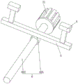
FIG. 1 is a schematic diagram of the structure of the present invention;
FIG. 2 is a side view of a first electrical putter in accordance with the present invention;
FIG. 3 is a side view of a first drive motor in accordance with the present invention;
FIG. 4 is a top view of an exhaust fan in the configuration of the present invention;
FIG. 5 is a top view of a second movable mechanism in the structure of the present invention;
fig. 6 is a top view of a splint in the structure of the present invention.
In the figure: 1. a body; 2. a work piece; 3. a conveying roller; 4. a clamping plate; 5. a cross frame; 6. a first movable mechanism; 601. a first ball nut; 602. a first ball screw; 7. cleaning brushes; 8. a short bar; 9. a second movable mechanism; 901. a second ball nut; 902. a second ball screw; 10. a roller brush assembly; 101. a bracket; 102. a round bar; 103. a brush body; 11. a dust hood; 12. an exhaust fan; 13. a column; 14. a hydraulic cylinder; 15. a movable plate; 16. an L-shaped plate; 17. a first electric push rod; 18. a base; 19. a rotating shaft; 20. a reinforcing plate; 21. a first driving motor; 22. a first chassis; 23. a mounting plate; 24. a second driving motor; 25. a support plate; 26. a second chassis; 27. a base; 28. a fixing plate; 29. an air outlet pipe; 30. an air inlet pipe; 31. an air guide pipe; 32. an air guiding pipe; 33. a telescopic tube; 34. a second electric push rod; 35. and a rectangular plate.
Detailed Description
The following description of the embodiments of the present invention will be made clearly and completely with reference to the accompanying drawings, in which it is apparent that the embodiments described are only some embodiments of the present invention, but not all embodiments. All other embodiments, which can be made by those skilled in the art based on the embodiments of the invention without making any inventive effort, are intended to be within the scope of the invention.
Referring to fig. 1 and 2, the present invention provides a technical solution: a four-column hydraulic press comprises a machine body 1 and a workpiece 2, wherein a conveying roller 3 is uniformly distributed on the front surface of the machine body 1, the conveying roller 3 rolls to facilitate the workpiece 2 to be placed into the upper end surface of a base 18, clamping plates 4 corresponding to the positions are arranged on the left side and the right side of the workpiece 2, the clamping plates 4 play a role in clamping the workpiece 2, stability of the workpiece 2 is reinforced, a transverse frame 5 positioned below the conveying roller 3 is fixedly arranged at the lower end of the clamping plates 4, the transverse frame 5 is arranged to connect the clamping plates 4 with a first movable mechanism 6, a first movable mechanism 6 is arranged in the middle of the transverse frame 5 and is far away from the clamping plates 4, power is provided for the movement of the clamping plates 4, the clamping plates 4 can be suitable for clamping workpieces 2 of different specifications, the applicable range of the clamping plates 4 is enlarged, the utilization rate of the clamping plates 4 is improved, a cleaning brush 7 is arranged above the workpiece 2, the cleaning brush 7 plays a role in cleaning the workpiece 2, a short rod 8 is fixedly arranged at the upper end of the clamping brush 7, a cleaning brush 7 is arranged on the cleaning brush 7, a second movable mechanism 9 is connected with the cleaning brush 9, a second movable mechanism 10 is arranged on the cleaning brush 2, a dust collecting component is fixedly arranged on the cleaning brush 11, and a dust collecting component is fixedly arranged on the right side of the workpiece 2, and is fixedly connected with the cleaning brush 2, and is provided with a dust collecting component 10. The arrangement of suction fan 12 provides power for the movement of the impurities.
The inner wall of organism 1 has fixedly cup jointed stand 13, stand 13's setting plays the connection effect to organism 1 and base 18, also be the restriction effect to fly leaf 15 motion track simultaneously, the inner wall fixed mounting of organism 1 has pneumatic cylinder 14, the setting of pneumatic cylinder 14 is the liftoff motion of fly leaf 15 provides power, the lower extreme fixedly connected with of the output shaft of pneumatic cylinder 14 is located fly leaf 15 of organism 1 below, and the inner wall of fly leaf 15 cup joints with stand 13's outer wall activity, the back fixed mounting of organism 1 has L shaped plate 16, L shaped plate 16's setting plays and provides support and platform for the installation of first electric putter 17, the positive fixedly connected with of L shaped plate 16 electric putter 17, the installation of first electric putter 17 plays the spacing effect to the time of putting into of machined part 2, utilize the motion of first electric putter 17 output shaft can also be with the ejecting effect of machined part 2, the lower extreme fixed mounting of stand 13 has the base 18 that is located the fly leaf 15 below, base 18 plays the support effect to the machined part 2, the positive fixed mounting of 1 has rectangular plate 35, the installation of plate 35 provides the rectangular plate 34 for the installation of second electric putter and the second electric putter 34 and the installation of second electric putter 34, the installation of second electric putter 34 provides the rectangular plate 34 and the fixed connection of second electric putter 34 to the motion platform.
Referring to fig. 3 and 6, a rotating shaft 19 is movably sleeved on the inner wall of the conveying roller 3, the installation of the rotating shaft 19 provides a support and a platform for the installation of the conveying roller 3, one end of the rotating shaft 19 is fixedly provided with a reinforcing plate 20, the rear end of the reinforcing plate 20 is fixedly connected with the front surface of the base 18, and the reinforcing plate 20 is arranged to provide a support function for the installation of the rotating shaft 19.
The first movable mechanism 6 comprises a first ball nut 601 fixedly mounted at the lower end of the transverse frame 5, the first ball nut 601 is arranged to provide power for the movement of the clamping plate 4, a first ball screw 602 is sleeved on the inner wall thread of the first ball nut 601, and the circumferential rotation of the first ball screw 602 provides power for the horizontal movement of the first ball nut 601.
One end fixed mounting of ball screw 602 has a driving motor 21, a driving motor 21's setting is the rotation of ball screw 602 and provides power, and be provided with a reduction gear on a driving motor 21's the output shaft, a reduction gear's setting is the regulating action of a driving motor 21's output shaft rotational speed, a chassis 22 has been cup jointed to a driving motor 21's outer wall is fixed, a chassis 22's setting is the installation of a driving motor 21 provides the support, also be the guard action to a driving motor 21 simultaneously, a chassis 22's one end fixedly connected with is located the outside mounting panel 23 of a movable mechanism 6, and the front fixed connection of mounting panel 23's back and base 18, mounting panel 23 plays the guard action to a movable mechanism 6.
Referring to fig. 4 and 5, the second moving mechanism 9 includes a second ball nut 901, the motion of the second ball nut 901 provides power for the motion of the short rod 8, so as to realize the reciprocating motion of the cleaning brush 7 on the surface of the workpiece 2, the lower end of the second ball nut 901 is fixedly connected with the upper end of the short rod 8, the inner wall thread of the second ball nut 901 is sleeved with a second ball screw 902, and the circumferential rotation of the second ball screw 902 provides power for the horizontal motion of the second ball nut 901.
The left end of the second ball screw 902 is fixedly provided with a second driving motor 24, the output of the second driving motor 24 is provided with a second speed reducer, the setting of the second speed reducer plays a role in regulating the rotation speed of an output shaft of the second driving motor 24, the outer wall of the second driving motor 24 is fixedly provided with a second chassis 26, the setting of the second chassis 26 plays a role in providing a platform for the installation of the second driving motor 24, the right end of the second chassis 26 is fixedly connected with a supporting plate 25 positioned outside the second movable mechanism 9, the upper end of the supporting plate 25 is fixedly provided with an air guide pipe 31, the setting of the air guide pipe 31 plays a role in connecting a telescopic pipe 33 with an air guide pipe 32, the upper end face of the air guide pipe 31 is fixedly connected with the lower end of an output shaft of the second electric push rod 34, the front and the back of the air guide pipe 31 are uniformly distributed with the air guide pipe 32, the installation of the air guide pipe 32 provides a platform for the installation of the dust hood 11, one end of the air guide pipe 32 away from the air guide pipe 31 is fixedly connected with the upper end of the dust hood 11, and the telescopic pipe 33 is fixedly arranged at the right end of the air guide pipe 31.
The roller brush assembly 10 comprises a support 101, the left side of the support 101 is fixedly connected with the right end of the cleaning brush 7, a round rod 102 is movably sleeved on the inner wall of the support 101, the round rod 102 is connected with the support 101 and a brush body 103, the brush body 103 is fixedly sleeved on the outer wall of the round rod 102, the brush body 103 rolls on a workpiece 2 in a avoided mode, impurities on the surface of the workpiece 2 are lifted, and cleaning of the impurities of the cleaning brush 7 is facilitated.
The lower extreme fixed mounting of air exhauster 12 has frame 27, the installation of frame 27 provides support and platform for the installation of air exhauster 12, one side fixedly connected with fixed plate 28 of air exhauster 12 is kept away from to frame 27, the setting of fixed plate 28 plays the connection to frame 27 and base 18, and the left end of fixed plate 28 and the right side fixed connection of base 18, the right side fixed mounting of air exhauster 12 has out tuber pipe 29, play the effect to the unified collection of impurity in the setting of play tuber pipe 29, the positive fixedly connected with air-supply line 30 of air exhauster 12, and the one end that air-supply line 30 kept away from air exhauster 12 and the lower extreme fixed connection of flexible pipe 33.
In summary, when the four-column hydraulic press is used, firstly, a workpiece 2 is placed on a conveying roller 3, a power supply of a first electric push rod 17 is started, the first electric push rod 17 drives the telescopic motion of an internal output shaft of the workpiece, the output shaft of the first electric push rod 17 stretches out to play a role in positioning the processing position of the workpiece 2, then, according to the thickness of the workpiece 2, a power supply of a second electric push rod 34, a first driving motor 21 and an exhaust fan 12 is started, the second electric push rod 34 drives the lifting motion of the internal output shaft in the vertical direction, the motion of the output shaft of the second electric push rod 34 drives a cleaning brush 7 to move towards the workpiece 2 until the bottom of the cleaning brush 7 and a roller brush assembly 10 are contacted with the upper end surface of the workpiece 2, the power supply of the second electric push rod 34 is closed, the first driving motor 21 drives the first ball screw 602 to rotate after being started, the first ball screw 602 drives the first ball nut 601 to move in the horizontal direction while rotating circumferentially, the first ball nut 601 drives the clamping plates 4 at the left side and the right side to move in the direction of the workpiece 2 through the connection of the transverse frame 5 until one side of the clamping plates 4 is contacted with the outer wall of the workpiece 2, the first driving motor 21 can be turned off, then, the power supply of the second driving motor 24 is turned on, the second driving motor 24 drives the second ball screw 902 to rotate after being turned on, the second ball screw 902 drives the second ball nut 901 to move in the horizontal direction while rotating circumferentially, the second ball nut 901 drives the cleaning brush 7 to move on the workpiece 2 through the connection of the short rod 8, the brush body 103 is driven to roll on the workpiece 2 along with the movement of the second ball nut 901, the brush body 103 plays a role in cleaning impurities attached to the surface of the workpiece 2 while rolling, the cleaning brush 7 cleans the surface of the workpiece 2 by the cleaned impurities of the brush body 103, at this time, the impurities during cleaning are sucked into the dust hood 11 due to the opening of the exhaust fan 12, then enter the air guide pipe 32, reach the inside of the telescopic pipe 33 after passing through the inside of the air guide pipe 31, then enter the inside of the exhaust fan 12 from the inside of the air inlet pipe 30, then be discharged from the inside of the air outlet pipe 29, the impurities can be uniformly collected, the impurities avoided by the workpiece 2 are prevented from being hydraulically pressed into the workpiece 2, thereby reducing the influence of the impurities on the processing of the workpiece 2, finally, the workpiece 2 is pushed to the upper end surface of the base 18 until the rear end surface of the workpiece 2 is contacted with the front end of the output shaft of the first electric push rod 17, then the power supply of the first electric push rod 17 is started to retract the output shaft of the first electric push rod 17, then the hydraulic cylinder 14 is used for controlling the movement of the movable plate 15 in the vertical direction, and the installation of the upright post 13 plays a role in lifting and adjusting the movable plate 15, thereby realizing the hydraulic processing of the workpiece 2 by the movable plate 15.
In the description of the present invention, it should be noted that, directions or positional relationships indicated by terms such as "center", "upper", "lower", "left", "right", "vertical", "horizontal", "inner", "outer", etc., are based on directions or positional relationships shown in the drawings, are merely for convenience of description and simplification of description, and do not indicate or imply that the apparatus or element to be referred to must have a specific direction, be constructed and operated in the specific direction, and thus should not be construed as limiting the present invention; the terms "first," "second," "third," and the like, are used for descriptive purposes only and are not to be construed as indicating or implying relative importance, and furthermore, unless explicitly specified and limited otherwise, the terms "mounted," "connected," "coupled," and the like are to be construed broadly, and may be fixedly coupled, detachably coupled, or integrally coupled, for example; can be mechanically or electrically connected; can be directly connected or indirectly connected through an intermediate medium, and can be communication between two elements. The specific meaning of the above terms in the present invention will be understood in specific cases by those of ordinary skill in the art. Moreover, the terms "comprises," "comprising," or any other variation thereof, are intended to cover a non-exclusive inclusion, such that a process, method, article, or apparatus that comprises a list of elements does not include only those elements but may include other elements not expressly listed or inherent to such process, method, article, or apparatus.
Although embodiments of the present invention have been shown and described, it will be understood by those skilled in the art that various changes, modifications, substitutions and alterations can be made therein without departing from the principles and spirit of the invention, the scope of which is defined in the appended claims and their equivalents.
Claims (9)
1. The utility model provides a four post hydraulic presses, includes organism (1), machined part (2), its characterized in that: the utility model discloses a cleaning machine for a workpiece, including organism (1), conveying roller (3) are evenly distributed in the front of organism (1), the left and right sides of machined part (2) all is provided with splint (4) that the position is corresponding, the lower extreme fixed mounting of splint (4) has crossbearer (5) that are located conveying roller (3) below, the mid-mounting that splint (4) one side was kept away from to crossbearer (5) has moving mechanism (6) No. one, the top of machined part (2) is provided with cleaning brush (7), the upper end normal mounting of cleaning brush (7) has quarter-turn (8), quarter-turn (8) are kept away from the one end of cleaning brush (7) and are installed No. two moving mechanism (9), the right side fixedly connected with roller brush subassembly (10) of cleaning brush (7), the top evenly distributed of machined part (2) has dust absorption hood (11), the right side fixed mounting of organism (1) has air exhauster (12).
2. A four column hydraulic machine according to claim 1, wherein: the utility model discloses a motor vehicle, including stand (13) have been cup jointed in the inner wall fixed of organism (1), the inner wall fixed mounting of organism (1) has pneumatic cylinder (14), the lower extreme fixedly connected with of the output shaft of pneumatic cylinder (14) is located fly leaf (15) of organism (1) below, and the inner wall of fly leaf (15) cup joints with the outer wall activity of stand (13), the back fixed mounting of organism (1) has L shaped plate (16), the positive fixedly connected with electric putter (17) of L shaped plate (16), the lower extreme fixed mounting of stand (13) has base (18) that are located fly leaf (15) below, the positive fixed mounting of organism (1) has rectangular board (35), the up end fixedly connected with No. two electric putter (34) of the output shaft of rectangular board (35), and the inner wall activity of the output shaft of No. two electric putter (34) cup joints.
3. A four column hydraulic machine according to claim 1, wherein: the inner wall activity of transfer roller (3) has cup jointed pivot (19), the one end fixed mounting of pivot (19) has gusset plate (20), and the front fixed connection of the rear end and base (18) of gusset plate (20).
4. A four column hydraulic machine according to claim 1, wherein: the first movable mechanism (6) comprises a first ball nut (601) fixedly arranged at the lower end of the transverse frame (5), and a first ball screw (602) is sleeved on the inner wall of the first ball nut (601) in a threaded manner.
5. A four column hydraulic machine as defined in claim 4 wherein: one end fixed mounting of ball screw (602) has a driving motor (21), and is provided with a reduction gear on the output shaft of driving motor (21), the outer wall of driving motor (21) is fixed to have cup jointed a quick-witted case (22), the one end fixedly connected with of a quick-witted case (22) is located the outside mounting panel (23) of a movable mechanism (6), and the front fixed connection of the back and base (18) of mounting panel (23).
6. A four column hydraulic machine according to claim 1, wherein: the second movable mechanism (9) comprises a second ball nut (901), the lower end of the second ball nut (901) is fixedly connected with the upper end of the short rod (8), and a second ball screw (902) is sleeved on the inner wall thread of the second ball nut (901).
7. A four column hydraulic machine as defined in claim 6 wherein: the left end of the second ball screw (902) is fixedly provided with a second driving motor (24), the output of the second driving motor (24) is provided with a second speed reducer, the outer wall of the second driving motor (24) is fixedly provided with a second case (26), the right end of the second case (26) is fixedly connected with a supporting plate (25) positioned outside the second movable mechanism (9), the utility model discloses a dust hood, including backup pad (25) and flexible pipe (31) right-hand member, upper end fixed mounting of backup pad (25) has guide duct (31), and the up end of guide duct (31) and the lower extreme fixed connection of the output shaft of No. two electric push rods (34), the front and the back evenly distributed of guide duct (31) have induced air pipe (32), and the one end that guide pipe (32) kept away from guide duct (31) is fixed connection with the upper end of dust hood (11), the right-hand member fixed mounting of guide duct (31) has flexible pipe (33).
8. A four column hydraulic machine according to claim 1, wherein: the roller brush assembly (10) comprises a support (101), the left side of the support (101) is fixedly connected with the right end of the cleaning brush (7), a round rod (102) is movably sleeved on the inner wall of the support (101), and a brush body (103) is fixedly sleeved on the outer wall of the round rod (102).
9. A four column hydraulic machine according to claim 1, wherein: the lower extreme fixed mounting of air exhauster (12) has frame (27), one side fixedly connected with fixed plate (28) of air exhauster (12) are kept away from to frame (27), and the left end of fixed plate (28) and the right side fixed connection of base (18), the right side fixed mounting of air exhauster (12) has air-out pipe (29), the positive fixedly connected with air-supply line (30) of air exhauster (12), and the one end that air-supply line (30) kept away from air exhauster (12) and the lower extreme fixed connection of flexible pipe (33).
Priority Applications (1)
| Application Number | Priority Date | Filing Date | Title |
|---|---|---|---|
| CN202310348929.2A CN116116774A (en) | 2023-04-04 | 2023-04-04 | Four-column hydraulic press |
Applications Claiming Priority (1)
| Application Number | Priority Date | Filing Date | Title |
|---|---|---|---|
| CN202310348929.2A CN116116774A (en) | 2023-04-04 | 2023-04-04 | Four-column hydraulic press |
Publications (1)
| Publication Number | Publication Date |
|---|---|
| CN116116774A true CN116116774A (en) | 2023-05-16 |
Family
ID=86310284
Family Applications (1)
| Application Number | Title | Priority Date | Filing Date |
|---|---|---|---|
| CN202310348929.2A Pending CN116116774A (en) | 2023-04-04 | 2023-04-04 | Four-column hydraulic press |
Country Status (1)
| Country | Link |
|---|---|
| CN (1) | CN116116774A (en) |
Cited By (1)
| Publication number | Priority date | Publication date | Assignee | Title |
|---|---|---|---|---|
| CN116922841A (en) * | 2023-07-29 | 2023-10-24 | 沧州久合汽车模具有限公司 | Frame type hydraulic machine with clamping mechanism and use method thereof |
Citations (7)
| Publication number | Priority date | Publication date | Assignee | Title |
|---|---|---|---|---|
| CN209521004U (en) * | 2018-10-22 | 2019-10-22 | 苏州昆仑绿建木结构科技股份有限公司 | A kind of hot press |
| CN212550634U (en) * | 2020-05-25 | 2021-02-19 | 盐城市大丰区中大机械有限公司 | Valve plate punching machine |
| CN212734005U (en) * | 2020-07-03 | 2021-03-19 | 江苏翔力重工科技有限公司 | Hydraulic-based stamping forging equipment |
| CN218227423U (en) * | 2022-08-17 | 2023-01-06 | 江苏顺乾新型材料有限公司 | Cleaning machine for recycling acrylic panel waste |
| CN218368696U (en) * | 2022-09-14 | 2023-01-24 | 广州塔拉卡电子有限公司 | Display screen packing plant |
| CN218394866U (en) * | 2022-10-31 | 2023-01-31 | 鑫统仕(江苏)换热系统有限公司 | Adjustable automatic tool for sweeping welding powder |
| CN115780631A (en) * | 2022-12-14 | 2023-03-14 | 江西安保智能科技有限公司 | Door lock hardware punch forming equipment and using method |
-
2023
- 2023-04-04 CN CN202310348929.2A patent/CN116116774A/en active Pending
Patent Citations (7)
| Publication number | Priority date | Publication date | Assignee | Title |
|---|---|---|---|---|
| CN209521004U (en) * | 2018-10-22 | 2019-10-22 | 苏州昆仑绿建木结构科技股份有限公司 | A kind of hot press |
| CN212550634U (en) * | 2020-05-25 | 2021-02-19 | 盐城市大丰区中大机械有限公司 | Valve plate punching machine |
| CN212734005U (en) * | 2020-07-03 | 2021-03-19 | 江苏翔力重工科技有限公司 | Hydraulic-based stamping forging equipment |
| CN218227423U (en) * | 2022-08-17 | 2023-01-06 | 江苏顺乾新型材料有限公司 | Cleaning machine for recycling acrylic panel waste |
| CN218368696U (en) * | 2022-09-14 | 2023-01-24 | 广州塔拉卡电子有限公司 | Display screen packing plant |
| CN218394866U (en) * | 2022-10-31 | 2023-01-31 | 鑫统仕(江苏)换热系统有限公司 | Adjustable automatic tool for sweeping welding powder |
| CN115780631A (en) * | 2022-12-14 | 2023-03-14 | 江西安保智能科技有限公司 | Door lock hardware punch forming equipment and using method |
Cited By (2)
| Publication number | Priority date | Publication date | Assignee | Title |
|---|---|---|---|---|
| CN116922841A (en) * | 2023-07-29 | 2023-10-24 | 沧州久合汽车模具有限公司 | Frame type hydraulic machine with clamping mechanism and use method thereof |
| CN116922841B (en) * | 2023-07-29 | 2024-08-23 | 沧州久合汽车模具有限公司 | Frame type hydraulic machine with clamping mechanism and use method thereof |
Similar Documents
| Publication | Publication Date | Title |
|---|---|---|
| CN112338649B (en) | Automatic grinding device for outer ring of precision motor bearing | |
| CN108723928B (en) | Novel four-station full-automatic chamfering machine | |
| CN116116774A (en) | Four-column hydraulic press | |
| CN116394131A (en) | Metal surface polishing device and method | |
| CN208628841U (en) | A kind of aluminium sheet coiled material cutting pressing one-shot forming apparatus | |
| CN112303939B (en) | Automatic cleaning equipment for heat collecting pipe of solar water heater | |
| CN208499600U (en) | A kind of cleaning device for food production | |
| CN106862267B (en) | A kind of lead pig decontamination preforming device of automatic charging | |
| CN217224961U (en) | Pipe section polishing cleaning machine | |
| CN109130477B (en) | Printing machine with automatic paper feeding and taking functions and capable of reducing dust pollution | |
| CN206826289U (en) | Ornaments organisation of working | |
| CN220920481U (en) | Continuous feeding cold roll forming device | |
| CN219882503U (en) | Lifting type single-shaft manipulator | |
| CN220030908U (en) | Automobile hose vulcanizing machine | |
| CN218395389U (en) | Delivery type angle steel straightening and flattening device | |
| CN217224366U (en) | Special welding seam back chipping equipment for full penetration welding of electric power iron tower | |
| CN220501887U (en) | Quick version device that goes up of possessing printing machine | |
| CN221185979U (en) | Scrap collecting device for processing inner core of steel coil | |
| CN221248083U (en) | Shaping device for forged cylinder flange plate | |
| CN220200875U (en) | Adjustable textile fabric conveyer | |
| CN215036259U (en) | High-efficient quick glass equipment of polishing | |
| CN221092757U (en) | Cold-rolled steel sheet loading attachment | |
| CN218554879U (en) | Material cleaning device presses with adjustable | |
| CN215612738U (en) | Roller coating equipment with flexible lifting structure | |
| CN221639610U (en) | Milling machine for processing die steel |
Legal Events
| Date | Code | Title | Description |
|---|---|---|---|
| PB01 | Publication | ||
| PB01 | Publication | ||
| SE01 | Entry into force of request for substantive examination | ||
| SE01 | Entry into force of request for substantive examination | ||
| RJ01 | Rejection of invention patent application after publication |
Application publication date: 20230516 |
|
| RJ01 | Rejection of invention patent application after publication |