CN116113223A - Communication comprehensive cabinet and assembling method thereof - Google Patents
Communication comprehensive cabinet and assembling method thereof Download PDFInfo
- Publication number
- CN116113223A CN116113223A CN202310293243.8A CN202310293243A CN116113223A CN 116113223 A CN116113223 A CN 116113223A CN 202310293243 A CN202310293243 A CN 202310293243A CN 116113223 A CN116113223 A CN 116113223A
- Authority
- CN
- China
- Prior art keywords
- cabinet
- cabinet shell
- wall
- shell
- communication
- Prior art date
- Legal status (The legal status is an assumption and is not a legal conclusion. Google has not performed a legal analysis and makes no representation as to the accuracy of the status listed.)
- Pending
Links
Images


Classifications
-
- H—ELECTRICITY
- H05—ELECTRIC TECHNIQUES NOT OTHERWISE PROVIDED FOR
- H05K—PRINTED CIRCUITS; CASINGS OR CONSTRUCTIONAL DETAILS OF ELECTRIC APPARATUS; MANUFACTURE OF ASSEMBLAGES OF ELECTRICAL COMPONENTS
- H05K7/00—Constructional details common to different types of electric apparatus
- H05K7/20—Modifications to facilitate cooling, ventilating, or heating
- H05K7/20009—Modifications to facilitate cooling, ventilating, or heating using a gaseous coolant in electronic enclosures
- H05K7/20136—Forced ventilation, e.g. by fans
-
- H—ELECTRICITY
- H05—ELECTRIC TECHNIQUES NOT OTHERWISE PROVIDED FOR
- H05K—PRINTED CIRCUITS; CASINGS OR CONSTRUCTIONAL DETAILS OF ELECTRIC APPARATUS; MANUFACTURE OF ASSEMBLAGES OF ELECTRICAL COMPONENTS
- H05K5/00—Casings, cabinets or drawers for electric apparatus
- H05K5/02—Details
- H05K5/0217—Mechanical details of casings
-
- H—ELECTRICITY
- H05—ELECTRIC TECHNIQUES NOT OTHERWISE PROVIDED FOR
- H05K—PRINTED CIRCUITS; CASINGS OR CONSTRUCTIONAL DETAILS OF ELECTRIC APPARATUS; MANUFACTURE OF ASSEMBLAGES OF ELECTRICAL COMPONENTS
- H05K7/00—Constructional details common to different types of electric apparatus
- H05K7/20—Modifications to facilitate cooling, ventilating, or heating
- H05K7/20009—Modifications to facilitate cooling, ventilating, or heating using a gaseous coolant in electronic enclosures
- H05K7/20136—Forced ventilation, e.g. by fans
- H05K7/20145—Means for directing air flow, e.g. ducts, deflectors, plenum or guides
-
- H—ELECTRICITY
- H05—ELECTRIC TECHNIQUES NOT OTHERWISE PROVIDED FOR
- H05K—PRINTED CIRCUITS; CASINGS OR CONSTRUCTIONAL DETAILS OF ELECTRIC APPARATUS; MANUFACTURE OF ASSEMBLAGES OF ELECTRICAL COMPONENTS
- H05K7/00—Constructional details common to different types of electric apparatus
- H05K7/20—Modifications to facilitate cooling, ventilating, or heating
- H05K7/20009—Modifications to facilitate cooling, ventilating, or heating using a gaseous coolant in electronic enclosures
- H05K7/20136—Forced ventilation, e.g. by fans
- H05K7/20181—Filters; Louvers
-
- H—ELECTRICITY
- H05—ELECTRIC TECHNIQUES NOT OTHERWISE PROVIDED FOR
- H05K—PRINTED CIRCUITS; CASINGS OR CONSTRUCTIONAL DETAILS OF ELECTRIC APPARATUS; MANUFACTURE OF ASSEMBLAGES OF ELECTRICAL COMPONENTS
- H05K7/00—Constructional details common to different types of electric apparatus
- H05K7/20—Modifications to facilitate cooling, ventilating, or heating
- H05K7/20218—Modifications to facilitate cooling, ventilating, or heating using a liquid coolant without phase change in electronic enclosures
- H05K7/20272—Accessories for moving fluid, for expanding fluid, for connecting fluid conduits, for distributing fluid, for removing gas or for preventing leakage, e.g. pumps, tanks or manifolds
-
- H—ELECTRICITY
- H05—ELECTRIC TECHNIQUES NOT OTHERWISE PROVIDED FOR
- H05K—PRINTED CIRCUITS; CASINGS OR CONSTRUCTIONAL DETAILS OF ELECTRIC APPARATUS; MANUFACTURE OF ASSEMBLAGES OF ELECTRICAL COMPONENTS
- H05K7/00—Constructional details common to different types of electric apparatus
- H05K7/20—Modifications to facilitate cooling, ventilating, or heating
- H05K7/2039—Modifications to facilitate cooling, ventilating, or heating characterised by the heat transfer by conduction from the heat generating element to a dissipating body
-
- Y—GENERAL TAGGING OF NEW TECHNOLOGICAL DEVELOPMENTS; GENERAL TAGGING OF CROSS-SECTIONAL TECHNOLOGIES SPANNING OVER SEVERAL SECTIONS OF THE IPC; TECHNICAL SUBJECTS COVERED BY FORMER USPC CROSS-REFERENCE ART COLLECTIONS [XRACs] AND DIGESTS
- Y02—TECHNOLOGIES OR APPLICATIONS FOR MITIGATION OR ADAPTATION AGAINST CLIMATE CHANGE
- Y02A—TECHNOLOGIES FOR ADAPTATION TO CLIMATE CHANGE
- Y02A20/00—Water conservation; Efficient water supply; Efficient water use
- Y02A20/108—Rainwater harvesting
Abstract
The invention discloses a communication comprehensive cabinet and an assembly method thereof, wherein the communication comprehensive cabinet comprises a cabinet shell and a cabinet door, the front side of the cabinet shell is of an opening structure, the cabinet door is rotatably arranged on the front side of the cabinet shell through a hinge, four supports which are symmetrically arranged in pairs are fixedly arranged at the bottom of the cabinet shell, an assembly plate is fixedly arranged in the cabinet shell, and a communication transmission equipment assembly is fixedly arranged on the front side wall of the assembly plate. The invention has reasonable design, can effectively cool the inside of the cabinet shell by utilizing the air cooling heat dissipation mechanism in rainy days, can effectively cool the inside of the cabinet shell by utilizing the water cooling heat dissipation mechanism in rainy days, and can further prevent rainwater from entering the inside of the cabinet shell, thereby realizing good heat dissipation effect, good waterproof and dustproof effects and better meeting the use requirements.
Description
Technical Field
The invention relates to the technical field of comprehensive cabinets, in particular to a communication comprehensive cabinet and an assembly method thereof.
Background
The communication comprehensive cabinet is a cabinet used in the aspect of communication, and mainly comprises a cabinet shell and a cabinet door which are formed by processing sheet metal equipment, wherein the space of the cabinet shell is used for storing and protecting communication transmission equipment such as a power supply, a motherboard, various expansion boards, a driver, a controller, a network communication switch, a signal transceiver, a signal converter, a cable and the like, and the parts are firmly fixed inside the cabinet shell through supporting parts, various screws or clamping parts and other connecting parts inside the cabinet shell to form an intensive type whole body for ensuring the normal operation of the communication transmission equipment.
At present, when the communication comprehensive cabinet is manufactured and put into use, a large amount of heat is generated when various communication transmission equipment installed in the communication comprehensive cabinet runs, a radiating hole is formed in the communication comprehensive cabinet to radiate heat and cool the inside of the communication comprehensive cabinet, dust impurities in the external environment are prevented from entering the inside of the communication comprehensive cabinet, a dust screen is installed at the radiating hole, and the communication comprehensive cabinet is required to be installed outdoors according to different use places, so that at least the following defects still exist when the communication comprehensive cabinet installed outdoors is found in actual use: when rainy day, rainwater gets into communication integrated cabinet inside from parts such as louvre easily, easily causes the communication transmission equipment of its interior installation to meet water and wet and damage, waterproof performance is not good to the dust screen is in natural environment for a long time, and the dust screen surface is easy adhesion more and more dust impurity, causes the mesh on the dust screen to block up, and the gas permeability is variation, and then can influence the radiating effect, can not satisfy the user demand, and for this reason, we propose a communication integrated cabinet and its assembly method and are used for solving above-mentioned problem.
Disclosure of Invention
Aiming at the defects of the prior art, the invention provides the communication comprehensive cabinet and the assembly method thereof, which solve the problems that when the communication comprehensive cabinet installed outdoors is in rainy days, rainwater easily enters the communication comprehensive cabinet from the parts such as the radiating holes, and the like, so that the communication transmission equipment installed in the communication comprehensive cabinet is easily damaged when the communication transmission equipment is wetted by water, the waterproof performance is poor, the dust screen is in natural environment for a long time, more dust impurities are easily adhered to the surface of the dust screen, the meshes on the dust screen are blocked, the air permeability is poor, the radiating effect is further influenced, and the use requirement cannot be met.
In order to achieve the above purpose, the present invention provides the following technical solutions: the utility model provides a cabinet is synthesized in communication, includes cabinet shell and cabinet door, cabinet shell's front side is the opening structure, and the cabinet door passes through the hinge rotation and installs in cabinet shell's front side, and cabinet shell's bottom fixed mounting has four to be the support that two liang of symmetries set up, and fixed mounting has the assembly plate in the cabinet shell, fixed mounting communication transmission equipment subassembly on the preceding lateral wall of assembly plate, has seted up two ventholes on cabinet shell's the top inner wall, and equal fixed mounting has first dust screen in two ventholes, is provided with forced air cooling mechanism and water-cooling mechanism on the cabinet shell.
Preferably, the air-cooled heat dissipation mechanism comprises two air inlet channels, two air suction fans and two second dustproof nets, wherein the two air inlet channels are respectively and fixedly installed on the left outer wall and the right outer wall of the cabinet shell, the two air inlet channels are communicated with the interior of the cabinet shell, the two air suction fans are respectively and fixedly installed in the corresponding air inlet channels, and the two second dustproof nets are respectively and fixedly installed on one sides, away from each other, of the two air inlet channels.
Preferably, the air-cooled heat dissipation mechanism further comprises a cross shaft, two cleaning brushes, a motor, a main gear and a pinion, wherein the cross shaft is positioned in the cabinet shell and positioned in front of the assembly plate, transverse holes are formed in the left inner wall and the right inner wall of the cabinet shell, the two transverse holes are respectively positioned below the corresponding air inlet channels, two ends of the cross shaft respectively penetrate through the corresponding transverse holes, two bearings are fixedly sleeved on the cross shaft, outer rings of the two bearings are respectively fixedly connected with the inner walls of the corresponding transverse holes, the two cleaning brushes are respectively and fixedly installed at two ends of the corresponding cross shaft, the motor is fixedly installed on the front side wall of the assembly plate, the main gear is fixedly installed at the output shaft end of the motor, the pinion is fixedly sleeved on the cross shaft, and the main gear is meshed with the pinion.
Preferably, the cleaning brush comprises a brush rod and brush hair, wherein the brush rod is fixedly connected with one end of the transverse shaft, the brush hair is fixedly arranged on the brush rod, and the brush hair is contacted with the second dust screen.
Preferably, the water cooling mechanism includes two cylinders, the rainwater collects the box, the grid board, two vertical baffle plates, the raceway, the heat-conducting plate, two outlet pipes and a plurality of restriction piece, two equal fixed mounting of cylinders are on the top inner wall of rack housing, two through-holes have been seted up on the top inner wall of rack housing, the output axle head of two cylinders runs through corresponding through-hole respectively, the rainwater is collected the box and is set up in the top of rack housing, the top of rainwater is the open construction, the output axle head of two cylinders all with the bottom fixed connection of rainwater collection box, grid board fixed mounting is in the rainwater is collected the box, two equal fixed mounting of vertical baffle plates are in the bottom of rainwater collection box and the symmetry sets up in the both sides of rack housing, bar hole has all been seted up on the top inner wall of two inlet channels, the bottom of two vertical baffle plates runs through corresponding bar hole respectively, raceway fixed mounting is in the bottom of rainwater collection box, heat-conducting plate fixed mounting is on the rear side wall of assembly plate, the cooling chamber has been seted up on the top inner wall of rack housing, the top inner wall of cooling chamber has seted up first round hole, the second round hole has been seted up on the top inner wall of cooling chamber, the bottom and two equal fixed mounting of water pipe and two equal cooling chamber and the left side are kept away from each other at the equal distance of two outlet pipes, the two equal cooling pipe sets up in the left side and the cooling chamber and the outside the outlet pipe is cooled down.
Preferably, the current limiting piece comprises a first shaft seat, a second shaft seat, a rotating shaft and a plurality of water blocking pieces, wherein the first shaft seat is fixedly arranged on the right inner wall of the cooling cavity, the second shaft seat is fixedly arranged on the left inner wall of the cooling cavity, two ends of the rotating shaft are respectively and rotatably connected with the first shaft seat and the second shaft seat, and the water blocking pieces are fixedly arranged on the rotating shaft and are distributed in an equidistant annular mode.
Preferably, a plurality of heat conducting fins are fixedly arranged on the left outer wall and the right outer wall of the heat conducting plate at equal intervals, a first sealing ring is fixedly arranged on the inner wall of the first round hole, a second sealing ring is fixedly arranged on the inner wall of the second round hole, the water pipe is in sliding sealing fit with the first round hole through the first sealing ring, and the water pipe is in sliding sealing fit with the second round hole through the second sealing ring.
Preferably, the two vertical baffles are fixedly arranged on one sides close to each other, and the two limiting plates are respectively contacted with the inner walls of the tops of the corresponding air inlet channels.
Preferably, a sealing strip is fixedly arranged on the inner wall of the strip-shaped hole, and the vertical baffle is in sliding sealing fit with the strip-shaped hole through the sealing strip.
The invention also provides an assembling method of the communication comprehensive cabinet, which comprises the following steps:
s1: firstly, mounting and fixing an assembly plate in a manufactured cabinet shell, then sequentially mounting and fixing a communication transmission equipment assembly on the assembly plate in a screw fixing mode, connecting cables and wires by a professional technician, sequentially mounting and fixing an air cooling heat dissipation mechanism and a water cooling heat dissipation mechanism on the cabinet shell, then mounting a manufactured cabinet door on the front side of the cabinet shell through a hinge, mounting a handle and a lock on the cabinet door, and finally fixing the manufactured four supports on the bottom of the cabinet shell in a screw fixing or welding mode to obtain the communication comprehensive cabinet;
s2: the communication comprehensive cabinet manufactured in the step S1 is placed on a test bed for detection and debugging, and is cleaned and tidied, so that the communication comprehensive cabinet meets the use standard;
s3: and (3) transporting the communication comprehensive cabinet detected and debugged in the step (S2) to an outdoor place to be installed and stably placing the communication comprehensive cabinet, fixing the four supports on the ground by adopting bolts, and connecting external wires such as a power line by a professional technician to perform communication signal transmission.
The invention provides a communication comprehensive cabinet and an assembly method thereof. The beneficial effects are as follows:
(1) According to the communication comprehensive cabinet and the assembling method thereof, the air cooling radiating mechanism formed by combining the two air inlet channels, the two air suction fans, the two second dustproof nets, the transverse shaft, the two cleaning brushes, the motor, the main gear and the auxiliary gear is utilized, when the weather is not rainy, the interior of the cabinet shell can be effectively cooled, radiated and cooled, good dustproof effects are achieved, the communication transmission equipment components inside the cabinet shell are prevented from being damaged due to high temperature during operation, the surfaces of the two second dustproof nets are cleaned by brushing, dust impurities are prevented from blocking meshes of the second dustproof nets, ventilation holes of the second dustproof nets can be improved, external air can smoothly enter the cabinet shell, and the air cooling radiating effect inside the cabinet shell is further improved.
(2) According to the communication comprehensive cabinet and the assembling method thereof, the water cooling mechanism which is formed by combining the two air cylinders, the rainwater collecting box, the grating plates, the two vertical baffle plates, the water conveying pipe, the heat conducting plate, the two water outlet pipes and the plurality of flow limiting pieces is utilized, and in rainy weather, the rainwater can be utilized to absorb heat in the cabinet shell to effectively cool the water, prevent the rainwater from entering the cabinet shell, and not only has a good heat dissipation effect, but also has a good waterproof and dustproof effect, and the communication transmission equipment component in the cabinet shell is prevented from being damaged due to high temperature or damp during operation.
(3) According to the communication comprehensive cabinet and the assembly method thereof, the flow limiting piece formed by combining the first shaft seat, the second shaft seat, the rotating shaft and the plurality of water retaining sheets is utilized, so that the falling speed of rainwater in the cooling cavity can be slowed down, the downward flowing time of the rainwater in the cooling cavity is prolonged, the heat in the cabinet shell can be absorbed more fully by utilizing the rainwater, and the water cooling and heat dissipation effect in the cabinet shell is further improved.
According to the invention, the air cooling heat dissipation mechanism is utilized to effectively cool the interior of the cabinet shell in rainless weather, and the water cooling heat dissipation mechanism is utilized to effectively cool the interior of the cabinet shell by absorbing heat of the cabinet shell in rainless weather, so that rainwater is prevented from entering the cabinet shell, good heat dissipation effect is achieved, meanwhile, good waterproof and dustproof effects are achieved, and the use requirements can be better met.
Drawings
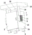
FIG. 1 is a schematic perspective view of a first view of the present invention;
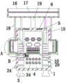
FIG. 2 is a schematic perspective view of a second view of the present invention;
FIG. 3 is a schematic cross-sectional view of the front view of the present invention;
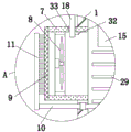
FIG. 4 is an enlarged schematic view of portion A of FIG. 3;
FIG. 5 is an enlarged schematic view of portion B of FIG. 3;
FIG. 6 is a schematic cross-sectional view of the rear view of the present invention;
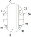
FIG. 7 is an enlarged schematic view of portion C of FIG. 6;
fig. 8 is a schematic cross-sectional perspective view of a heat-conducting plate.
In the figure: 1. a cabinet housing; 2. a cabinet door; 3. a support; 4. an assembly plate; 5. an air outlet hole; 6. a first dust screen; 7. an air inlet channel; 8. an air suction fan; 9. a second dust screen; 10. a horizontal axis; 11. a cleaning brush; 12. a motor; 13. a main gear; 14. a pinion gear; 15. a cylinder; 16. a rainwater collection box; 17. a grating plate; 18. a vertical baffle; 19. a water pipe; 20. a heat conductive plate; 21. a cooling chamber; 22. a first round hole; 23. a second round hole; 24. a water outlet pipe; 25. a first shaft seat; 26. a second axle seat; 27. a rotating shaft; 28. a water blocking piece; 29. a heat conduction fin; 30. a first seal ring; 31. a second seal ring; 32. a limiting plate; 33. a sealing strip; 34. a communication transmission device assembly.
Description of the embodiments
The following description of the embodiments of the present invention will be made clearly and completely with reference to the accompanying drawings, in which it is apparent that the embodiments described are only some embodiments of the present invention, but not all embodiments. All other embodiments, which can be made by those skilled in the art based on the embodiments of the invention without making any inventive effort, are intended to be within the scope of the invention.
As shown in fig. 1-8, the present invention provides a technical solution: the utility model provides a communication synthesizes cabinet, including cabinet shell 1 and cabinet door 2, cabinet shell 1's front side is the opening structure, cabinet door 2 rotates the front side of installing at cabinet shell 1 through the hinge, cabinet door 2 is used for sealed shielding to cabinet shell 1's front side opening part, cabinet shell 1's bottom fixed mounting has four to be support 3 that two liang symmetry set up, utilize four support 3, can cushion up cabinet shell 1 to ground certain distance, when avoiding raining, the rainwater gathers and causes cabinet shell 1's bottom to soak in the rainwater, wherein:
the cabinet shell 1 is internally and fixedly provided with an assembly plate 4, the front side wall of the assembly plate 4 is fixedly provided with a communication transmission equipment component 34, the assembly plate 4 is made of stainless steel materials or aluminum alloy materials, so that the assembly plate 4 has good strength and good heat conduction effect, the communication transmission equipment component 34 is composed of electric elements such as a power supply, a motherboard, various expansion boards, a driver, a controller, a network communication switch, a signal transceiver, a signal converter, a cable and the like, and is used for communication transmission, the top inner wall of the cabinet shell 1 is provided with two air outlet holes 5, the two air outlet holes 5 are internally and fixedly provided with a first dustproof net 6, the two air outlet holes 5 are arranged so as to facilitate heat dissipation in the cabinet shell 1, dust in the external environment can be prevented from entering the cabinet shell 1 from the first dustproof net 6 by utilizing the first dustproof net 6, the cabinet shell 1 is provided with an air cooling heat dissipation mechanism and a water cooling heat dissipation mechanism, the air cooling heat dissipation mechanism is used for sucking external air into the cabinet shell 1 to realize the aim of effectively cooling the interior of the cabinet shell 1 by air cooling, the air cooling heat dissipation mechanism comprises two air inlet channels 7, two air suction fans 8, two second dustproof nets 9, a transverse shaft 10, two cleaning brushes 11, a motor 12, a main gear 13 and a pinion 14, the two air inlet channels 7 are respectively and fixedly arranged on the left outer wall and the right outer wall of the cabinet shell 1, the two air inlet channels 7 are communicated with the interior of the cabinet shell 1, the two air suction fans 8 are respectively and fixedly arranged in the corresponding air inlet channels 7, the two second dustproof nets 9 are respectively and fixedly arranged on one sides of the two air inlet channels 7 which are far away from each other, and the operation of the two air suction fans 8 is utilized, external air can be sucked into the cabinet shell 1, and the air entering the interior of the cabinet shell 1 can generate convection by utilizing the two air suction fans 8, so that the air can be widely diffused, the effect of air cooling and heat dissipation in the interior of the cabinet shell 1 is improved, dust in the external environment can be prevented from entering the cabinet shell 1 through the air inlet channel 7 by utilizing the two second dustproof nets 9, the dust prevention effect is achieved, the transverse shaft 10 is positioned in the cabinet shell 1 and in front of the assembly plate 4, the left side inner wall and the right side inner wall of the cabinet shell 1 are respectively provided with a transverse hole, the two transverse holes are respectively positioned below the corresponding air inlet channel 7, the two ends of the transverse shaft 10 respectively penetrate through the corresponding transverse holes, two bearings are fixedly sleeved on the transverse shaft 10, the outer rings of the two bearings are respectively fixedly connected with the inner walls of the corresponding transverse holes, the two cleaning brushes 11 are respectively fixedly arranged at the two ends of the corresponding transverse shaft 10, the motor 12 is fixedly arranged on the front side wall of the assembly plate 4, the main gear 13 is fixedly arranged at the output shaft end of the motor 12, the auxiliary gear 14 is fixedly sleeved on the transverse shaft 10, the main gear 13 is meshed with the auxiliary gear 14, the main gear 13 can be driven to rotate by the motor 12, the transverse shaft 10 can be controlled to drive the two cleaning brushes 11 to rotate by the meshing transmission action of the main gear 13 and the auxiliary gear 14, the cleaning brushes 11 can be used for brushing away dust impurities adhered to the surface of the second dust screen 9, the good air permeability of the second dust screen 9 is maintained, the heat dissipation effect on the inside of the cabinet shell 1 is further improved, the water cooling and heat dissipation mechanism comprises two air cylinders 15, a rainwater collecting box 16, a grid plate 17, two vertical baffle plates 18, a water delivery pipe 19, a heat conduction plate 20, two water outlet pipes 24 and a plurality of current limiting pieces, the two air cylinders 15 are fixedly arranged on the top inner wall of the cabinet shell 1, the inner wall of the top of the cabinet shell 1 is provided with two through holes, the output shaft ends of the two air cylinders 15 respectively penetrate through the corresponding through holes, the rainwater collection box 16 is arranged above the cabinet shell 1, the top of the rainwater collection box 16 is of an opening structure, the output shaft ends of the two air cylinders 15 are fixedly connected with the bottom of the rainwater collection box 16, the two air cylinders 15 can control the rainwater collection box 16 to rise or fall, the grid plate 17 is fixedly arranged in the rainwater collection box 16, the rainwater collection box 16 is used for receiving rainwater, the grid plate 17 is used for intercepting and blocking sundries falling into the rainwater collection box 16, the surface sundries enter the water pipe 19, the cross section size of the rainwater collection box 16 is larger than the cross section size of the cabinet shell 1, the grid plate 17 is made of stainless steel materials, the two vertical baffles 18 are fixedly arranged at the bottom of the rainwater collection box 16 and symmetrically arranged at two sides of the cabinet shell 1, the top inner walls of the two air inlet channels 7 are respectively provided with strip-shaped holes, the bottoms of the two vertical baffle plates 18 respectively penetrate through the corresponding strip-shaped holes, the two vertical baffle plates 18 are utilized to respectively seal the interiors of the corresponding air inlet channels 7, so that rainwater can be prevented from entering the cabinet shell 1 from the air inlet channels 7 in rainy days, the water pipe 19 is fixedly arranged at the bottom of the rainwater collecting box 16, the heat conducting plate 20 is fixedly arranged on the rear side wall of the assembly plate 4, the heat conducting plate 20 is internally provided with the cooling cavity 21, the water pipe 19 can be utilized to guide rainwater into the cooling cavity 21, heat generated during operation of the communication transmission equipment assembly 34 can be transmitted into the rainwater through the assembly plate 4 by utilizing the heat transfer characteristic of the heat conducting plate 20, the top inner wall of the cabinet shell 1 is provided with the first round hole 22, the top inner wall of the cooling cavity 21 is provided with the second round hole 23, the bottom of raceway 19 runs through first round hole 22 and second round hole 23 in proper order, two outlet pipes 24 are fixed mounting respectively in the left side and the right side of heat-conducting plate 20, two outlet pipes 24 all are linked together with cooling chamber 21, the one end that two outlet pipes 24 kept away from each other all extends outside cabinet shell 1, a plurality of current limiting parts all set up in cooling chamber 21 and are equidistant vertical arranging, foretell current limiting part is used for blockking the rainwater that falls into cooling chamber 21, can effectually slow down the speed that the rainwater freely falls in cooling chamber 21, and then can prolong the time that the rainwater flows down in cooling chamber 21, can utilize the rainwater to more abundant absorption of heat inside cabinet shell 1, first axle bed 25 fixed mounting is on the right side inner wall of cooling chamber 21, second axle bed 26 fixed mounting is on the left side inner wall of cooling chamber 21, the both ends of pivot 27 respectively with first axle bed 25 and second axle bed 26 rotation connection, a plurality of water blocking plates 28 all fixed mounting are equidistant and are arranged in the pivot 27 and are the speed that makes the rainwater that falls down in cooling chamber 21 freely, and can utilize the multiple water blocking plates 28 to apply to the rainwater through equidistant ring-shaped water blocking plates 28, and then the rainwater can be applied to the rainwater that the rainwater can be slowed down to the speed of the rainwater 28.
In this embodiment, the cleaning brush 11 includes a brush rod and bristles, the brush rod is fixedly connected with one end of the transverse shaft 10, the bristles are fixedly mounted on the brush rod, the bristles are in contact with the second dust screen 9, the brush rod can be made of plastic, and the bristles can be made of nylon brush filaments, so that the brush rod and the bristles have good wear resistance and corrosion resistance, and have long service life.
In this embodiment, a plurality of heat conducting fins 29 are fixedly installed at equal intervals on the left side outer wall and the right side outer wall of the heat conducting plate 20, the contact range with hot air inside the cabinet housing 1 can be enlarged by utilizing the plurality of heat conducting fins 29, further, heat can be more comprehensively transferred to rainwater in the cooling cavity 21, the effect of water cooling and heat dissipation is improved, the heat conducting plate 20 and the plurality of heat conducting fins 29 are made of aluminum materials or copper materials with good heat conductivity, a first sealing ring 30 is fixedly installed on the inner wall of the first circular hole 22, a second sealing ring 31 is fixedly installed on the inner wall of the second circular hole 23, the water conveying pipe 19 is in sliding sealing fit with the first circular hole 22 through the first sealing ring 30, the water conveying pipe 19 is in sliding sealing fit with the second circular hole 23 through the second sealing ring 31, gaps between the water conveying pipe 19 and the first circular hole 22 can be sealed by utilizing the first sealing ring 30, rainwater dust can be prevented from entering the cabinet housing 1 from the gaps between the water conveying pipe 19 and the first circular hole 22, gaps between the water conveying pipe 19 and the second circular hole 23 can be prevented from overflowing from the gaps between the second circular hole 23 and the water conveying pipe 19.
In this embodiment, the two vertical baffles 18 are fixedly mounted with limiting plates 32 on the sides close to each other, the two limiting plates 32 are respectively contacted with the top inner walls of the corresponding air inlet channels 7, and the lifting stroke of the vertical baffles 18 can be limited by using the limiting plates 32.
In this embodiment, the sealing strip 33 is fixedly installed on the inner wall of the strip-shaped hole, the vertical baffle 18 is in sliding sealing fit with the strip-shaped hole through the sealing strip 33, and the sealing strip 33 can seal the gap between the vertical baffle 18 and the strip-shaped hole, so that rainwater and dust are prevented from entering the cabinet shell 1 through the gap between the vertical baffle 18 and the strip-shaped hole.
In this embodiment, it should be noted that, the control switch is installed inside the cabinet housing 1, and the two air suction fans 8, the motor 12, the two air cylinders 15 and the control switch are electrically connected with the external power line sequentially through wires, and the control switch can be used for controlling the start and stop of the two air suction fans 8 and the motor 12, and also can be used for controlling the start and stop and reset of the two air cylinders 15.
In summary, the communication comprehensive cabinet provided by the invention can effectively cool the inside of the cabinet shell 1 by utilizing the air cooling heat dissipation mechanism in rainy days, can effectively cool the inside of the cabinet shell 1 by utilizing the rainwater to absorb heat in the cabinet shell 1 by utilizing the water cooling heat dissipation mechanism in rainy days, further can prevent rainwater from entering the inside of the cabinet shell 1, realizes good heat dissipation effect, has good waterproof and dustproof effects, can better meet the use requirement, and can be used for communication transmission by fixing the whole communication comprehensive cabinet at an outdoor proper position and connecting wires in specific operation, when in rainy days, the outside air can be controlled to be sucked into the cabinet shell 1 through the two air inlet channels 7 by starting the operation of the two air suction fans 8, the hot air in the cabinet shell 1 is discharged from the two air outlet holes 5, the purpose of air cooling and heat dissipation in the cabinet shell 1 is realized, dust impurities in the external environment can be blocked and intercepted by utilizing the two first dustproof nets 6 and the two second dustproof nets 9, dust is prevented from entering the cabinet shell 1, the purpose of dust prevention is achieved, the air entering the cabinet shell 1 can be more comprehensively diffused and blown to the surface of the communication transmission equipment assembly 34 by utilizing the air entering the cabinet shell 1 from the two air inlet channels 7, the air cooling and heat dissipation effect in the cabinet shell 1 can be improved, the high temperature generated during the operation of the communication transmission equipment assembly 34 is avoided from being damaged, the operation of the unscheduled starting motor 12 is utilized, the meshing transmission effect of the main gear 13 and the auxiliary gear 14 is utilized, the transverse shaft 10 can be controlled to drive the two cleaning brushes 11 to rotate, the two cleaning brushes 11 are utilized to brush away dust and impurities adhered to the surfaces of the two second dustproof nets 9, so that the dust and impurities are prevented from blocking meshes on the second dustproof nets 9, ventilation holes of the second dustproof nets 9 can be improved, external air can smoothly enter the cabinet shell 1, the air cooling heat dissipation effect of the interior of the cabinet shell 1 is further improved, in rainy days, the two air suction fans 8 are closed, the two air cylinders 15 are started to reset, the rainwater collecting box 16 can be controlled to drive the grid plate 17, the two vertical baffle plates 18 and the water conveying pipe 19 to vertically move downwards, when the bottom of the rainwater collecting box 16 is abutted against the top of the cabinet shell 1, the two air cylinders 15 are stopped to operate, at the moment, the bottoms of the two vertical baffle plates 18 are respectively contacted with the inner walls of the bottoms of the corresponding air inlet channels 7, the corresponding air inlet channels 7 can be respectively blocked by the two vertical baffle plates 18, the rainwater is prevented from entering the cabinet shell 1 from the air inlet channel, the purpose of water prevention is achieved, meanwhile, the rainwater can be collected by utilizing the rainwater collecting box 16, the collected rainwater falls into the cooling cavity 21 through the water pipe 19, the heat in the cabinet shell 1 can be transferred to the rainwater through the assembly plate 4, the heat conducting plate 20 and the plurality of heat conducting fins 29 by utilizing the continuous downward flow of the rainwater in the cooling cavity 21, the rainwater absorbing the heat can be discharged out of the cabinet shell 1 from the two water outlet pipes 24, the purpose of water cooling and heat dissipation in the cabinet shell 1 is achieved, when the rainwater continuously flows downwards in the cooling cavity 21, the plurality of water retaining plates 28 and the rotating shaft 27 can be pushed to rotate by utilizing the acting force generated when the rainwater flows downwards, the falling speed of the rainwater in the cooling cavity 21 is further slowed down, the downward flow time of the rainwater in the cooling cavity 21 is prolonged, can utilize the rainwater to the inside heat more abundant absorption of cabinet shell 1, further improve the water-cooling radiating effect to cabinet shell 1 inside, produce high temperature and damage when avoiding communication transmission equipment subassembly 34 to move, after the rain stop, through starting two cylinder 15 work, steerable rainwater collection box 16 drives grid board 17, two perpendicular baffles 18 and raceway 19 and vertically moves up, when limiting plate 32 on two perpendicular baffles 18 are inconsistent with the top inner wall of corresponding air inlet channel 7 respectively, stop two cylinder 15 operations, open two suction fans 8 again and can continue to carry out forced air cooling heat dissipation cooling to cabinet shell 1 inside.
The invention provides an assembly method of a communication comprehensive cabinet, which comprises the following steps:
s1: firstly, mounting and fixing an assembly plate 4 in a manufactured cabinet shell 1, then sequentially mounting and fixing a communication transmission equipment assembly 34 on the assembly plate 4 in a screw fixing mode, connecting cables and wires by a professional technician, sequentially mounting and fixing an air cooling heat dissipation mechanism and a water cooling heat dissipation mechanism on the cabinet shell 1, then mounting the manufactured cabinet door 2 on the front side of the cabinet shell 1 through 2-3 hinges, mounting handles and locks on the cabinet door 2, and finally fixing the manufactured four supports 3 on the bottom of the cabinet shell 1 in a screw fixing or welding mode to obtain the communication comprehensive cabinet;
s2: the communication comprehensive cabinet manufactured in the step S1 is placed on a test bed for detection and debugging, and is cleaned and tidied, so that the communication comprehensive cabinet meets the use standard;
s3: the communication comprehensive cabinet detected and debugged in the step S2 is transported to an outdoor place where the communication comprehensive cabinet needs to be installed and placed stably, the four supports 3 are fixed on the ground by bolts, and then the professional technician is connected with external wires such as a power line, so that the communication comprehensive cabinet can be put into use for communication signal transmission.
It is noted that relational terms such as first and second, and the like are used solely to distinguish one entity or action from another entity or action without necessarily requiring or implying any actual such relationship or order between such entities or actions. Moreover, the terms "comprises," "comprising," or any other variation thereof, are intended to cover a non-exclusive inclusion, such that a process, method, article, or apparatus that comprises a list of elements does not include only those elements but may include other elements not expressly listed or inherent to such process, method, article, or apparatus. Without further limitation, the element defined by the phrase "comprising one … …" does not exclude the presence of other identical elements in a process, method, article, or apparatus that comprises the element, while elements not specifically described in the present specification are well known to those of ordinary skill in the art.
Although embodiments of the present invention have been shown and described, it will be understood by those skilled in the art that various changes, modifications, substitutions and alterations can be made therein without departing from the principles and spirit of the invention, the scope of which is defined in the appended claims and their equivalents.
Claims (10)
1. The utility model provides a communication synthesizes cabinet, its characterized in that, including cabinet shell (1) and cabinet door (2), the front side of cabinet shell (1) is open structure, cabinet door (2) are installed through the hinge rotation cabinet shell (1) front side, the bottom fixed mounting of cabinet shell (1) has four support (3) that are two liang symmetry setting, fixed mounting has assembly plate (4) in cabinet shell (1), fixed mounting communication transmission equipment subassembly (34) on the preceding lateral wall of assembly plate (4), two ventholes (5) have been seted up on the top inner wall of cabinet shell (1), two equal fixed mounting has first dust screen (6) in venthole (5), be provided with forced air cooling mechanism and water cooling mechanism on cabinet shell (1).
2. A telecommunications complex cabinet according to claim 1, wherein: the air cooling heat dissipation mechanism comprises two air inlet channels (7), two air suction fans (8) and two second dustproof nets (9), wherein the two air inlet channels (7) are respectively fixedly installed on the left outer wall and the right outer wall of the cabinet shell (1), the two air inlet channels (7) are respectively communicated with the inside of the cabinet shell (1), the two air suction fans (8) are respectively fixedly installed in the corresponding air inlet channels (7), and the two second dustproof nets (9) are respectively fixedly installed on one sides of the two air inlet channels (7) which are far away from each other.
3. A telecommunications complex cabinet according to claim 2, wherein: the air-cooled heat dissipation mechanism further comprises a transverse shaft (10), two cleaning brushes (11), a motor (12), a main gear (13) and a pinion (14), wherein the transverse shaft (10) is positioned in the cabinet shell (1) and positioned in front of the assembly plate (4), transverse holes are formed in the left inner wall and the right inner wall of the cabinet shell (1), the two transverse holes are respectively positioned below the corresponding air inlet channel (7), the two ends of the transverse shaft (10) respectively penetrate through the corresponding transverse holes, two bearings are fixedly sleeved on the transverse shaft (10), the outer rings of the two bearings are respectively fixedly connected with the inner walls of the corresponding transverse holes, the two cleaning brushes (11) are respectively fixedly installed at the two ends of the corresponding transverse shaft (10), the motor (12) is fixedly installed on the front side wall of the assembly plate (4), the main gear (13) is fixedly installed at the output shaft end of the motor (12), and the pinion (14) is fixedly sleeved on the transverse shaft (10), and the outer rings of the two bearings (13) are meshed with the pinion (14).
4. A telecommunications closet as claimed in claim 3, wherein: the cleaning brush (11) comprises a brush rod and brush hair, the brush rod is fixedly connected with one end of the transverse shaft (10), the brush hair is fixedly arranged on the brush rod, and the brush hair is in contact with the second dust screen (9).
5. A telecommunications complex cabinet according to claim 2, wherein: the water cooling mechanism comprises two air cylinders (15), a rainwater collecting box (16), a grid plate (17), two vertical baffle plates (18), a water conveying pipe (19), a heat conducting plate (20), two water outlet pipes (24) and a plurality of flow limiting pieces, wherein the two air cylinders (15) are fixedly installed on the inner wall of the top of the cabinet shell (1), two through holes are formed in the inner wall of the top of the cabinet shell (1), the output shaft ends of the two air cylinders (15) respectively penetrate through the corresponding through holes, the rainwater collecting box (16) is arranged above the cabinet shell (1), the top of the rainwater collecting box (16) is in an opening structure, the output shaft ends of the two air cylinders (15) are fixedly connected with the bottom of the rainwater collecting box (16), the grid plate (17) is fixedly installed in the rainwater collecting box (16), the two vertical baffle plates (18) are fixedly installed on the bottom of the cabinet shell (1) and symmetrically arranged on two sides of the cabinet shell (1), the two strip-shaped baffle plates (20) are fixedly installed on the bottom of the strip-shaped water conveying pipe (16) respectively, the cooling device is characterized in that a cooling cavity (21) is formed in the heat conducting plate (20), a first round hole (22) is formed in the inner wall of the top of the cabinet shell (1), a second round hole (23) is formed in the inner wall of the top of the cooling cavity (21), the bottom end of the water conveying pipe (19) sequentially penetrates through the first round hole (22) and the second round hole (23), two water outlet pipes (24) are fixedly mounted on the left side and the right side of the heat conducting plate (20) respectively, two water outlet pipes (24) are communicated with the cooling cavity (21), one ends, away from each other, of the two water outlet pipes (24) are all extended to the outside of the cabinet shell (1), and a plurality of flow limiting pieces are arranged in the cooling cavity (21) and are vertically distributed at equal intervals.
6. A telecommunications complex cabinet according to claim 5, wherein: the flow limiting piece comprises a first shaft seat (25), a second shaft seat (26), a rotating shaft (27) and a plurality of water blocking pieces (28), wherein the first shaft seat (25) is fixedly installed on the right inner wall of the cooling cavity (21), the second shaft seat (26) is fixedly installed on the left inner wall of the cooling cavity (21), two ends of the rotating shaft (27) are respectively connected with the first shaft seat (25) and the second shaft seat (26) in a rotating mode, and the water blocking pieces (28) are fixedly installed on the rotating shaft (27) and are distributed in an equidistant annular mode.
7. A telecommunications complex cabinet according to claim 5, wherein: a plurality of heat conducting fins (29) are fixedly arranged on the left side outer wall and the right side outer wall of the heat conducting plate (20) at equal intervals, a first sealing ring (30) is fixedly arranged on the inner wall of the first round hole (22), a second sealing ring (31) is fixedly arranged on the inner wall of the second round hole (23), the water conveying pipe (19) is in sliding sealing fit with the first round hole (22) through the first sealing ring (30), and the water conveying pipe (19) is in sliding sealing fit with the second round hole (23) through the second sealing ring (31).
8. A telecommunications complex cabinet according to claim 5, wherein: and one side, close to each other, of each vertical baffle (18) is fixedly provided with a limiting plate (32), and each limiting plate (32) is respectively contacted with the inner wall at the top of the corresponding air inlet channel (7).
9. A telecommunications complex cabinet according to claim 5, wherein: and a sealing strip (33) is fixedly arranged on the inner wall of the strip-shaped hole, and the vertical baffle (18) is in sliding sealing fit with the strip-shaped hole through the sealing strip (33).
10. A method of assembling a telecommunications closet as claimed in any one of claims 1 to 9 comprising the steps of:
s1: firstly, mounting and fixing an assembly plate (4) in a manufactured cabinet shell (1), then sequentially mounting and fixing a communication transmission equipment assembly (34) on the assembly plate (4) in a screw fixing mode, connecting cables and wires by a professional technician, sequentially mounting and fixing an air cooling heat dissipation mechanism and a water cooling heat dissipation mechanism on the cabinet shell (1), then mounting the manufactured cabinet door (2) on the front side of the cabinet shell (1) through 2-3 hinges, mounting handles and locks on the cabinet door (2), and finally fixing the manufactured four supports (3) on the bottom of the cabinet shell (1) in a screw fixing or welding mode to obtain the communication comprehensive cabinet;
s2: the communication comprehensive cabinet manufactured in the step S1 is placed on a test bed for detection and debugging, and is cleaned and tidied, so that the communication comprehensive cabinet meets the use standard;
s3: the communication comprehensive cabinet detected and debugged in the step S2 is transported to an outdoor place where the communication comprehensive cabinet needs to be installed and placed stably, the four supports (3) are fixed on the ground by bolts, and then the professional technician is connected with external wires such as a power line, so that the communication comprehensive cabinet can be put into use for communication signal transmission.
Priority Applications (1)
| Application Number | Priority Date | Filing Date | Title |
|---|---|---|---|
| CN202310293243.8A CN116113223A (en) | 2023-03-24 | 2023-03-24 | Communication comprehensive cabinet and assembling method thereof |
Applications Claiming Priority (1)
| Application Number | Priority Date | Filing Date | Title |
|---|---|---|---|
| CN202310293243.8A CN116113223A (en) | 2023-03-24 | 2023-03-24 | Communication comprehensive cabinet and assembling method thereof |
Publications (1)
| Publication Number | Publication Date |
|---|---|
| CN116113223A true CN116113223A (en) | 2023-05-12 |
Family
ID=86260024
Family Applications (1)
| Application Number | Title | Priority Date | Filing Date |
|---|---|---|---|
| CN202310293243.8A Pending CN116113223A (en) | 2023-03-24 | 2023-03-24 | Communication comprehensive cabinet and assembling method thereof |
Country Status (1)
| Country | Link |
|---|---|
| CN (1) | CN116113223A (en) |
Cited By (1)
| Publication number | Priority date | Publication date | Assignee | Title |
|---|---|---|---|---|
| CN116887547A (en) * | 2023-07-31 | 2023-10-13 | 中国通信建设第三工程局有限公司 | Sensor-based digital information transmission device for communication |
-
2023
- 2023-03-24 CN CN202310293243.8A patent/CN116113223A/en active Pending
Cited By (2)
| Publication number | Priority date | Publication date | Assignee | Title |
|---|---|---|---|---|
| CN116887547A (en) * | 2023-07-31 | 2023-10-13 | 中国通信建设第三工程局有限公司 | Sensor-based digital information transmission device for communication |
| CN116887547B (en) * | 2023-07-31 | 2024-03-29 | 中国通信建设第三工程局有限公司 | Sensor-based digital information transmission device for communication |
Similar Documents
| Publication | Publication Date | Title |
|---|---|---|
| CN210725871U (en) | Cooling device for server cabinet of computer room | |
| CN116113223A (en) | Communication comprehensive cabinet and assembling method thereof | |
| CN111542208A (en) | Circulating air-draft type dust removal and heat dissipation device for electromechanical equipment | |
| CN219716371U (en) | Outdoor full-color LED display screen heat abstractor | |
| CN211267328U (en) | Energy-saving outdoor communication air-cooled cabinet | |
| CN219203881U (en) | Cooling device based on photovoltaic power generation | |
| CN114151851B (en) | Efficient household radiator | |
| CN213244228U (en) | 5G communication cabinet with heat radiation structure | |
| CN212011708U (en) | Rainproof type switch board | |
| CN220733341U (en) | Electrical control box for electromechanical integrated equipment | |
| CN216017564U (en) | Heat dissipation device for power converter | |
| CN220368966U (en) | Dual cooling type communication base station cabinet | |
| CN216259668U (en) | Cooling tower speed reducer with heat sink | |
| CN212304404U (en) | Switch board that possesses dust removal function | |
| CN219041198U (en) | Box body structure of electric power control box | |
| CN220493097U (en) | Switch with quick heat radiation structure | |
| CN215185427U (en) | Block terminal convenient to ventilation cooling | |
| CN216121300U (en) | Power distribution cabinet multiple heat dissipation structure for power grid | |
| CN214676359U (en) | Heat dissipation rack of power environment control | |
| CN218920828U (en) | Heat abstractor of equipment control cabinet | |
| CN211239042U (en) | Heat dissipation device for power distribution cabinet | |
| CN216564132U (en) | A protective structure for hydraulic engineering | |
| CN220711909U (en) | Security protection control rack that radiating effect is good | |
| CN219394181U (en) | Heat abstractor of transformer substation | |
| CN216352127U (en) | Quick radiating computer machine case |
Legal Events
| Date | Code | Title | Description |
|---|---|---|---|
| PB01 | Publication | ||
| PB01 | Publication | ||
| SE01 | Entry into force of request for substantive examination | ||
| SE01 | Entry into force of request for substantive examination |