CN116102148A - Pigment-containing wastewater circulating adsorption equipment - Google Patents
Pigment-containing wastewater circulating adsorption equipment Download PDFInfo
- Publication number
- CN116102148A CN116102148A CN202310391566.0A CN202310391566A CN116102148A CN 116102148 A CN116102148 A CN 116102148A CN 202310391566 A CN202310391566 A CN 202310391566A CN 116102148 A CN116102148 A CN 116102148A
- Authority
- CN
- China
- Prior art keywords
- fixedly connected
- side wall
- rod
- lateral wall
- basin
- Prior art date
- Legal status (The legal status is an assumption and is not a legal conclusion. Google has not performed a legal analysis and makes no representation as to the accuracy of the status listed.)
- Granted
Links
Images


Classifications
-
- C—CHEMISTRY; METALLURGY
- C02—TREATMENT OF WATER, WASTE WATER, SEWAGE, OR SLUDGE
- C02F—TREATMENT OF WATER, WASTE WATER, SEWAGE, OR SLUDGE
- C02F1/00—Treatment of water, waste water, or sewage
- C02F1/52—Treatment of water, waste water, or sewage by flocculation or precipitation of suspended impurities
- C02F1/5281—Installations for water purification using chemical agents
-
- B—PERFORMING OPERATIONS; TRANSPORTING
- B01—PHYSICAL OR CHEMICAL PROCESSES OR APPARATUS IN GENERAL
- B01F—MIXING, e.g. DISSOLVING, EMULSIFYING OR DISPERSING
- B01F29/00—Mixers with rotating receptacles
- B01F29/60—Mixers with rotating receptacles rotating about a horizontal or inclined axis, e.g. drum mixers
- B01F29/63—Mixers with rotating receptacles rotating about a horizontal or inclined axis, e.g. drum mixers with fixed bars, i.e. stationary, or fixed on the receptacle
-
- C—CHEMISTRY; METALLURGY
- C02—TREATMENT OF WATER, WASTE WATER, SEWAGE, OR SLUDGE
- C02F—TREATMENT OF WATER, WASTE WATER, SEWAGE, OR SLUDGE
- C02F2209/00—Controlling or monitoring parameters in water treatment
- C02F2209/11—Turbidity
-
- C—CHEMISTRY; METALLURGY
- C02—TREATMENT OF WATER, WASTE WATER, SEWAGE, OR SLUDGE
- C02F—TREATMENT OF WATER, WASTE WATER, SEWAGE, OR SLUDGE
- C02F2209/00—Controlling or monitoring parameters in water treatment
- C02F2209/40—Liquid flow rate
Abstract
The invention discloses pigment-containing wastewater circulating adsorption equipment, and relates to the technical field of wastewater treatment. This kind of pigment-containing waste water circulation adsorption equipment, including the basin, the lateral wall of basin is fixed to be inserted and is equipped with first turbidity sensor and velocity of flow sensor, and the bottom fixedly connected with bottom plate of basin, the arc wall has been seted up at the top of bottom plate, and the inside wall of basin is connected with the live-rollers through the pivot rotation, the lateral wall fixedly connected with driving motor of basin, and driving motor's output is fixed with the one end of pivot. Can be to containing pigment waste water continuous non-stop adsorption treatment for it is more abundant, the effect is better to mix, simultaneously, is convenient for collect and handle the sediment after the waste water adsorbs, and can circulate adsorption treatment to waste water, guarantees waste water treatment's efficiency and effect.
Description
Technical Field
The invention relates to the technical field of wastewater treatment, in particular to pigment-containing wastewater circulating adsorption equipment.
Background
Pigment-containing wastewater generated in beverage production requires adsorption of pigment in the pigment wastewater by an adsorption device before discharge, and during adsorption, coagulant must be added to the wastewater to adsorb pigment and then precipitate the pigment.
However, when the existing pigment-containing wastewater adsorption equipment is used, the mixing of the coagulant and wastewater is not uniform and sufficient enough, so that the adsorption effect and efficiency are affected, meanwhile, the sediment formed after adsorption is inconvenient to collect and treat, the adsorption effect and efficiency are also affected, and the cyclic adsorption is inconvenient to adsorb the incomplete wastewater, so that the treatment effect and efficiency of pigment-containing wastewater are affected.
Disclosure of Invention
The invention aims to provide pigment-containing wastewater circulating adsorption equipment so as to solve the problems in the background technology.
In order to achieve the above purpose, the present invention provides the following technical solutions: the utility model provides a contain pigment waste water circulation adsorption equipment, includes the basin, the fixed first turbidity sensor and the flow velocity sensor of inserting of lateral wall of basin, and the bottom fixedly connected with bottom plate of basin, the arc wall has been seted up at the top of bottom plate, and the inside wall of basin is connected with the live-rollers through the pivot rotation, the lateral wall fixedly connected with driving motor of basin, and driving motor's output is fixed with the one end of pivot, the lateral wall of live-rollers is provided with a plurality of adsorption apparatus that are used for carrying out absorbing to the waste water pigment, and the lateral wall of basin is provided with and is used for carrying out circulation absorbing circulation mechanism to the waste water.
Preferably, the circulation mechanism comprises a second turbidity sensor fixedly inserted into the side wall of the water tank, a sealing plate is inserted into the water tank, the side wall of the sealing plate is fixedly connected with a first connecting block, the lower side wall of the first connecting block is fixedly connected with a first loop bar, the side wall of the first loop bar is sleeved with a first sleeve, the lower end of the first sleeve is fixed with the top of the water tank, the side wall of the sealing plate is fixedly connected with a second connecting block, the lower side wall of the second connecting block is rotationally connected with a first threaded rod, the side wall of the first threaded rod is in threaded connection with a first threaded sleeve, the lower end of the first threaded sleeve is fixed with the top of the water tank, the upper side wall of the second connecting block is fixedly connected with a first motor, the output end of the first motor is fixed with the upper end of the first threaded rod, the side wall of the water tank is fixedly connected with a water pump, a water inlet pipe is fixedly connected between the water inlet end of the water pump and the water tank, and a water outlet pipe is fixedly connected between the water outlet end of the water pump and the water tank.
Preferably, each adsorption mechanism includes the medicine storage box of fixed connection at the rotor side wall, and the medicine feeding mouth has been seted up to the bottom of medicine storage box, the reaction cover that the bottom fixedly connected with cavity of medicine storage box set up, and a plurality of crisscross swash plates that set up of fixedly connected with in the reaction cover, the bottom of reaction cover is rotated through rotary mechanism and is connected with the arc cover, and the delivery port has been seted up to the side wall of arc cover, fixedly connected with filter screen in the delivery port, and the water inlet has been seted up to the side wall of reaction cover, the collecting vat that the slope set up downwards has been fixedly inserted to the side wall of basin, and the filtration pore has been seted up to the bottom of collecting vat, be provided with the adjustment mechanism who is used for adjusting the medicine feeding speed in the medicine storage box, and the side wall of reaction cover is provided with the knocking mechanism that is used for beating the arc cover vibrations.
Preferably, the adjustment mechanism includes sliding connection at the movable plate that two symmetries set up in the medicine chest bottom, and the movable plate includes first inclined plane, each the lateral wall fixedly connected with movable rod of movable plate, the lateral wall cover of movable rod is equipped with first spring, and the other end of movable rod runs through the lateral wall of medicine chest and fixedly connected with disc, the lateral wall cover of movable rod is equipped with flexible pipe, and the removal of movable plate promotes through first pushing mechanism.
Preferably, the first pushing mechanism comprises a first T-shaped guide rod fixedly connected to two symmetrical parts of the side wall of the medicine storage box, a sliding plate is sleeved on the side wall of the first T-shaped guide rod, two symmetrically arranged pushing blocks are fixedly connected to the side wall of the sliding plate and comprise a second inclined plane, a second spring is sleeved on the side wall of the first T-shaped guide rod, a first pushing rod is fixedly connected to the side wall of the sliding plate, an arc-shaped block is inserted into the side wall of the water tank and comprises a third inclined plane, and the arc-shaped block is connected with the side wall of the water tank through a moving mechanism.
Preferably, the moving mechanism comprises a second sleeve fixedly connected to the side wall of the water tank, a second sleeve rod is inserted in the second sleeve rod, a third connecting block is fixedly connected to the other end of the second sleeve rod, the arc-shaped block is fixed to the lower side wall of the third connecting block, a second threaded rod is rotatably connected to the side wall of the third connecting block, a second threaded sleeve is connected to the side wall of the second threaded rod in a threaded manner, the second threaded sleeve is fixed to the side wall of the water tank, a second motor is fixedly connected to the side wall of the third connecting block, and the output end of the second motor is fixed to one end of the second threaded rod.
Preferably, the rotating mechanism comprises a fixed block fixedly connected to the side wall of the reaction cover, the side wall of the fixed block is rotationally connected with two symmetrically arranged rotating blocks through a first rotating rod, the rotating blocks are fixed to the side wall of the arc-shaped cover, and the rotation of the first rotating rod is driven through a driving mechanism.
Preferably, the actuating mechanism includes the first L shaped plate that two symmetries of fixed connection set up at reaction cover lateral wall, and the lateral wall fixedly connected with of first L shaped plate two dead levers that the symmetry set up, the lateral wall cover of dead lever is equipped with the rack, and the lateral wall fixedly connected with second push rod of rack, the lateral wall cover of dead lever is equipped with the third spring, and the first arch that a plurality of arrays of inside wall fixedly connected with of basin set up, the lateral wall fixedly connected with backup pad of reaction cover, and the lateral wall of backup pad is connected with the gear through the rotation of second dwang, and gear and rack meshing set up, the lateral wall fixed cover of second dwang is equipped with driven bevel gear, and the lateral wall fixed cover of first dwang is equipped with driving bevel gear.
Preferably, the knocking mechanism comprises a fixed plate fixedly connected to the side wall of the arc-shaped cover, the side wall of the supporting plate is fixedly connected with a second L-shaped plate, the side wall of the second L-shaped plate is fixedly connected with two symmetrically arranged second T-shaped guide rods, the side wall of the second T-shaped guide rods is sleeved with a moving block, the side wall of the second T-shaped guide rods is sleeved with a fourth spring, the side wall of the moving block is fixedly connected with a knocking rod, and the moving of the moving block is pushed by a second pushing mechanism.
Preferably, the second pushing mechanism comprises a rotating disc fixedly connected to the lower end of the second rotating rod, and the side wall of the rotating disc is fixedly connected with a plurality of second bulges arranged in an array.
Compared with the prior art, the invention has the beneficial effects that:
this kind of contain pigment waste water circulation adsorption equipment through setting up adsorption equipment, vibration mechanism and circulation mechanism etc. can be to containing pigment waste water continuous non-stop adsorption treatment for mix more abundant, the effect is better, simultaneously, is convenient for collect and handle the sediment after the waste water adsorbs, and can circulate adsorption treatment to waste water, guarantees waste water treatment's efficiency and effect.
Drawings
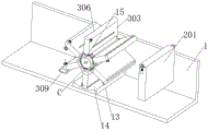
FIG. 1 is a schematic diagram of the overall structure of the present invention;
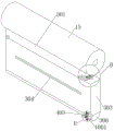
FIG. 2 is a schematic view of the overall structure of another view of the present invention;
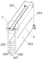
FIG. 3 is a schematic cross-sectional view of a sink according to the present invention;
FIG. 4 is a schematic view of the positions of the rotating roller and the adsorbing mechanism according to the present invention;
FIG. 5 is a schematic view showing the positions of the rotating roller and the suction mechanism according to another view angle of the present invention;
FIG. 6 is a schematic cross-sectional view of an adsorption mechanism according to the present invention;
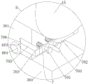
FIG. 7 is an enlarged schematic view of the structure of FIG. 1A;
FIG. 8 is an enlarged schematic view of the structure shown at B in FIG. 2;
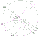
FIG. 9 is an enlarged schematic view of the structure of FIG. 3C;
FIG. 10 is an enlarged schematic view of the structure of FIG. 5D;
FIG. 11 is an enlarged schematic view of the structure of FIG. 5E;
fig. 12 is an enlarged schematic view of the structure at F in fig. 6.
In the figure: 1. a water tank; 2. a circulation mechanism; 201. a second turbidity sensor; 202. a sealing plate; 203. a first connection block; 204. a first loop bar; 205. a first sleeve; 206. a second connection block; 207. a first threaded sleeve; 208. a first threaded rod; 209. a first motor; 210. a water inlet pipe; 211. a water outlet pipe; 212. a water pump; 3. an adsorption mechanism; 301. a medicine storage box; 302. a medicine adding port; 303. a reaction cover; 304. a water inlet; 305. a sloping plate; 306. an arc-shaped cover; 307. a water outlet; 308. a filter screen; 309. a collection tank; 310. filtering holes; 4. a rotating mechanism; 401. a rotating block; 402. a first rotating lever; 403. a fixed block; 5. a second pushing mechanism; 501. a rotating disc; 502. a second protrusion; 6. an adjusting mechanism; 601. a moving plate; 602. a first inclined surface; 603. a moving rod; 604. a disc; 605. a first spring; 606. a telescopic tube; 7. a first pushing mechanism; 701. a first T-shaped guide bar; 702. a sliding plate; 703. a second spring; 704. a first push rod; 705. a pushing block; 706. a second inclined surface; 707. an arc-shaped block; 708. a third inclined surface; 8. a moving mechanism; 801. a second sleeve; 802. a second loop bar; 803. a second threaded sleeve; 804. a second threaded rod; 805. a second motor; 806. a third connecting block; 9. a driving mechanism; 901. a first L-shaped plate; 902. a fixed rod; 903. a rack; 904. a third spring; 905. a second push rod; 906. a first protrusion; 907. a support plate; 908. a second rotating lever; 909. a gear; 910. a driven bevel gear; 911. a drive bevel gear; 10. a knocking mechanism; 1001. a fixing plate; 1002. a second L-shaped plate; 1003. a second T-shaped guide bar; 1004. a moving block; 1005. a fourth spring; 1006. knocking the rod; 11. a first turbidity sensor; 12. a flow rate sensor; 13. a bottom plate; 14. an arc-shaped groove; 15. a rotating roller; 16. and driving the motor.
Detailed Description
The following description of the embodiments of the present invention will be made clearly and completely with reference to the accompanying drawings, in which it is apparent that the embodiments described are only some embodiments of the present invention, but not all embodiments. All other embodiments, which can be made by those skilled in the art based on the embodiments of the invention without making any inventive effort, are intended to be within the scope of the invention.
Referring to fig. 1-12, the present invention provides a technical solution: the utility model provides a contain pigment waste water circulation adsorption equipment, including basin 1, basin 1's lateral wall is fixed to be inserted and is equipped with first turbidity sensor 11 and velocity of flow sensor 12, and basin 1's bottom fixedly connected with bottom plate 13, arc wall 14 has been seted up at bottom plate 13's top, and basin 1's inside wall is connected with rotor roll 15 through the pivot rotation, basin 1's lateral wall fixedly connected with driving motor 16, and driving motor 16's output is fixed with the one end of pivot, rotor roll 15's lateral wall is provided with a plurality of adsorption mechanisms 3 that are used for carrying out absorbing to the waste water pigment, and basin 1's lateral wall is provided with and is used for carrying out circulation absorbing circulation mechanism 2 to the waste water, can be to contain pigment waste water continuous non-stop adsorption treatment, make the mixture more abundant, the effect is better, simultaneously, be convenient for collect and handle the sediment after the waste water absorption, and, can circulate adsorption treatment to waste water, waste water treatment's efficiency and effect are guaranteed.
Referring to fig. 1 and 2, the circulation mechanism 2 includes a second turbidity sensor 201 fixedly inserted into a side wall of the water tank 1, a sealing plate 202 is inserted into the water tank 1, a first connecting block 203 is fixedly connected to the side wall of the sealing plate 202, a first sleeve 204 is fixedly connected to the lower side wall of the first connecting block 203, a first sleeve 205 is sleeved on the side wall of the first sleeve 204, the lower end of the first sleeve 205 is fixedly connected to the top of the water tank 1, a second connecting block 206 is fixedly connected to the side wall of the sealing plate 202, the lower side wall of the second connecting block 206 is rotatably connected with a first threaded rod 208, a first threaded sleeve 207 is connected to the side wall of the first threaded rod 208 in threaded connection, the lower end of the first threaded sleeve 207 is fixedly connected to the top of the water tank 1, a first motor 209 is fixedly connected to the upper end of the first connecting block 208, a water pump 212 is fixedly connected to the side wall of the water pump 212, a water inlet end of the water pump 212 is fixedly connected to the water inlet pipe 210, a water outlet end of the water pump 212 is fixedly connected to the water tank 1, a water outlet pipe 211 is fixedly connected to the top of the water tank 1, a first threaded rod 208 is rotatably connected to the water outlet pipe 211, a first threaded rod is rotatably connected to the water outlet pipe 211 through the second threaded sleeve 207, and the first threaded rod 208 is rotatably connected to the water outlet pipe 211, and the first threaded rod is enabled to be continuously subjected to the sewage treatment by the first threaded rod 209, and the first threaded rod is enabled to be continuously and the sewage to be adsorbed by the sewage through the first threaded rod 209.
Referring to fig. 1-6, each adsorption mechanism 3 includes a medicine storage box 301 fixedly connected to the side wall of a rotating roller 15, and a medicine adding port 302 is formed in the bottom of the medicine storage box 301, a plurality of inclined plates 305 are fixedly connected to the bottom of the medicine storage box 301 and are arranged in a staggered manner, an arc cover 306 is rotatably connected to the bottom of the reaction cover 303 through a rotating mechanism 4, a water outlet 307 is formed in the side wall of the arc cover 306, a filter screen 308 is fixedly connected to the water outlet 307, a water inlet 304 is formed in the side wall of the reaction cover 303, a collecting tank 309 which is arranged obliquely downwards is fixedly inserted in the side wall of the water tank 1, a filter hole 310 is formed in the bottom of the collecting tank 309, an adjusting mechanism 6 for adjusting the medicine adding speed is arranged in the medicine storage box 301, a knocking mechanism 10 for knocking the arc cover 306 is arranged on the side wall of the reaction cover 303, a driving motor 16 is started when waste water is processed, the rotation of the driving motor 16 drives the rotating roller 15 and the adsorption mechanism 3 to rotate anticlockwise, when the water inlet 304 is positioned below the liquid surface 304, the water inlet 304 enters the reaction cover 6, a filter screen 308 is arranged in the reaction cover 302, and the filter screen 302 is further mixed with the waste water after the waste water is mixed with the waste water, the waste water is mixed and is mixed with the waste water, the waste water is mixed with the waste water is discharged in the filter screen 302, and the waste water is mixed with the waste water is completely, and the waste water is mixed with the waste water is filtered by the waste water is completely, and the waste water is mixed by the waste water is discharged in the filter tank is continuously after the waste water is mixed by the filter medium through the filter tank 302, and the filter tank is mixed with the filter medium and the filter medium after the waste water is mixed with the waste material is mixed with the sewage through the filter tank and the filter tank is further completely and further filtered by the filter medium and further effectively and further completely and further mixed with the filter medium and the filter medium after the waste medium and the waste medium is further reaches the waste medium after the waste is further is mixed.
Referring to fig. 10 and 12, the adjusting mechanism 6 includes two moving plates 601 which are symmetrically arranged at the bottom of the medicine storage tank 301 and are slidably connected, the moving plates 601 include a first inclined plane 602, the side walls of the moving plates 601 are fixedly connected with moving rods 603, the side walls of the moving rods 603 are sleeved with first springs 605, the other ends of the moving rods 603 penetrate through the side walls of the medicine storage tank 301 and are fixedly connected with discs 604, the side walls of the moving rods 603 are sleeved with telescopic tubes 606, the moving of the moving plates 601 is pushed by a first pushing mechanism 7, when wastewater enters through the water inlet 304, the two moving plates 601 are pushed to move away from each other by the first pushing mechanism 7, the first springs 605 are compressed, at this time, the medicine feeding openings 302 are opened, and coagulant in the medicine storage tank 301 enters into the reaction cover 303 through the medicine feeding openings 302.
Referring to fig. 9 and 10, the first pushing mechanism 7 includes a first T-shaped guide rod 701 fixedly connected to two symmetrical side walls of the medicine storage tank 301, a sliding plate 702 is sleeved on the side wall of the first T-shaped guide rod 701, two symmetrically arranged pushing blocks 705 are fixedly connected to the side wall of the sliding plate 702, the pushing blocks 705 include a second inclined plane 706, the disc 604 slides on the second inclined plane 706, a second spring 703 is sleeved on the side wall of the first T-shaped guide rod 701, a first pushing rod 704 is fixedly connected to the side wall of the sliding plate 702, an arc-shaped block 707 is inserted into the outer side wall of the water tank 1, the other end of the arc-shaped block 707 penetrates into the water tank 1, the arc-shaped block 704 includes a third inclined plane 708, and the arc-shaped block 707 is connected to the side wall of the water tank 1 through a moving mechanism 8, when the rotating roller 15 rotates, the end of the first pushing rod 704 slides along the third inclined plane 708 and the side wall of the arc-shaped block 707, so that the first pushing rod 704 and the sliding plate 702 are pushed to move away from the arc-shaped block 706, so that the disc 604 is driven to move synchronously, so that the two side walls 601 of the disc 604 move away from the second inclined plane 706.
Referring to fig. 7, the moving mechanism 8 includes a second sleeve 801 fixedly connected to the side wall of the water tank 1, a second sleeve 802 is inserted into the second sleeve 801, a third connecting block 806 is fixedly connected to the other end of the second sleeve 802, and the arc-shaped block 707 is fixed to the lower side wall of the third connecting block 806, the side wall of the third connecting block 806 is rotatably connected to a second threaded rod 804, the side wall of the second threaded rod 804 is screwed with a second threaded sleeve 803, the second threaded sleeve 803 is fixed to the side wall of the water tank 1, the side wall of the third connecting block 806 is fixedly connected to a second motor 805, and the output end of the second motor 805 is fixed to one end of the second threaded rod 804, turbidity and flow rate of the wastewater are detected by a first turbidity sensor 11 and a flow rate sensor 12, respectively, and according to the detection result, the second motor 805 is started, the rotation of the second motor 805 drives the rotation of the second threaded rod 804, and then drives the movement of the arc-shaped block 707, thereby adjusting the movement stroke of the first pushing rod 704, and further adjusting the distance of the two moving plates 601 when opening, and further adjusting the size of the dosing port 302 and the dosing speed.
Referring to fig. 8 and 11, the rotation mechanism 4 includes a fixed block 403 fixedly connected to a side wall of the reaction housing 303, and the side wall of the fixed block 403 is rotationally connected to two symmetrically arranged rotation blocks 401 through a first rotation rod 402, the rotation blocks 401 are fixed to the side wall of the arc-shaped housing 306, and the rotation of the first rotation rod 402 is driven by a driving mechanism 9, so as to ensure the normal rotation of the arc-shaped housing 306.
Referring to fig. 8 and 11, the driving mechanism 9 includes a first L-shaped plate 901 fixedly connected to two symmetrically disposed side walls of the reaction housing 303, two symmetrically disposed fixing rods 902 are fixedly connected to the side walls of the first L-shaped plate 901, racks 903 are sleeved on the side walls of the fixing rods 902, second pushing rods 905 are fixedly connected to the side walls of the racks 903, third springs 904 are sleeved on the side walls of the fixing rods 902, a plurality of first protrusions 906 disposed in an array are fixedly connected to the inner side walls of the water tank 1, a supporting plate 907 is fixedly connected to the side walls of the reaction housing 303, a gear 909 is rotatably connected to the side walls of the supporting plate 907 through a second rotating rod 908, the gear 909 is fixed to the upper end of the second rotating rod 908, the gear 909 is meshed with the racks 903, driven bevel gears 910 are fixedly sleeved on the side walls of the second rotating rod 908, driving bevel gears 910 are fixedly sleeved on the side walls of the first rotating rod 402, when the reaction cover 303 rotates from sewage to above the liquid level, when the end part of the second push rod 905 is propped against the side wall of the first bulge 906, the second push rod 905 is pushed to move and drives the rack 903 to synchronously move, meanwhile, the third spring 904 is compressed, when the end part of the second push rod 905 passes over the side wall of the first bulge 906, the rack 903 can move and reset under the action of the third spring 904, so that the rack 903 reciprocates, when the rack 903 reciprocates, the gear 909 and the second rotating rod 908 are driven to reciprocate, when the second rotating rod 908 rotates, the driven bevel gear 910 and the driving bevel gear 911 are driven to rotate, the arc cover 306 is driven to rotate along the first rotating rod 402, and reciprocating rotation is realized to open and close, so that a shaking effect is formed, and the sediment in the arc cover 306 can be conveniently and uniformly collected after falling into the collecting groove 309, thereby being convenient for collect and process the sediment after the waste water absorption, and further ensuring the efficiency and effect of waste water treatment.
Referring to fig. 8 and 11, the knocking mechanism 10 includes a fixing plate 1001 fixedly connected to a side wall of the arc-shaped cover 306, and a second L-shaped plate 1002 fixedly connected to a side wall of a supporting plate 907, two symmetrically arranged second T-shaped guide rods 1003 are fixedly connected to a side wall of the second L-shaped plate 1002, a moving block 1004 is sleeved on a side wall of the second T-shaped guide rods 1003, a fourth spring 1005 is sleeved on a side wall of the second T-shaped guide rods 1003, and a knocking rod 1006 is fixedly connected to a side wall of the moving block 1004, the moving block 1004 is pushed by a second pushing mechanism 5, and when the arc-shaped cover 306 rotates, the moving block 1004 and the knocking rod 1006 are pushed by the second pushing mechanism 5 to reciprocate, so that the knocking rod 1006 performs reciprocating knocking vibration on the side wall of the fixing plate 1001, and transmits the vibration to the arc-shaped cover 306, and thus sediment in the arc-shaped cover 306 is collected uniformly after falling into the collecting groove 309.
Referring to fig. 11, the second pushing mechanism 5 includes a rotating disc 501 fixedly connected to a lower end of a second rotating rod 908, and a plurality of second protrusions 502 arranged in an array are fixedly connected to a side wall of the rotating disc 501, when the second rotating rod 908 rotates, the rotating disc 501 is driven to rotate synchronously, and when the second protrusions 502 are propped against a side wall of the moving block 1004, the moving block 1004 and the knocking rod 1006 are pushed to move.
Working principle: when the device is used, during wastewater treatment, the driving motor 16 is started, the rotation of the driving motor 16 drives the rotating roller 15 and the adsorption mechanism 3 to rotate anticlockwise, when the water inlet 304 is below the liquid level, wastewater enters the reaction cover 303 through the water inlet 304, and the end part of the first pushing rod 704 slides along the side walls of the third inclined surface 708 and the arc block 707, so that the first pushing rod 704 and the sliding plate 702 are pushed to move in the direction away from the arc block 707, the pushing block 705 is driven to synchronously move, the disc 604 slides on the side wall of the second inclined surface 706, so that the two moving plates 601 are pushed to move away from each other, the first spring 605 is compressed, at the moment, the dosing port 302 is opened, the coagulant in the drug storage tank 301 enters the reaction cover 303 through the dosing port 302 and is mixed with the wastewater, and is collided and mixed for multiple times under the action of the inclined plate 305, the mixed is more sufficient and better, the adsorbed wastewater is filtered through the filter screen 308 and then discharged, and the adsorbed sediment is trapped in the arc cover 306, so that the dye-containing wastewater can be continuously and discontinuously treated, the adsorption efficiency and the wastewater treatment effect are ensured;
the turbidity and the flow rate of the wastewater are detected by the first turbidity sensor 11 and the flow rate sensor 12 respectively, the second motor 805 is started according to the detection result, the rotation of the second motor 805 drives the rotation of the second threaded rod 804, and further drives the movement of the arc-shaped block 707, so that the movement stroke of the first pushing rod 704 is adjusted, and further the distance between the two moving plates 601 when opened is adjusted, and further the size of the dosing port 302 and the dosing speed are adjusted;
when the reaction cover 303 rotates from sewage to above the liquid level, when the end part of the second push rod 905 is propped against the side wall of the first bulge 906, the second push rod 905 is pushed to move and drives the rack 903 to synchronously move, meanwhile, the third spring 904 is compressed, when the end part of the second push rod 905 passes over the side wall of the first bulge 906, the rack 903 can move and reset under the action of the third spring 904, so that the rack 903 reciprocates, when the rack 903 reciprocates, the gear 909 and the second rotating rod 908 are driven to reciprocate, and when the second rotating rod 908 rotates, the driven bevel gear 910 and the driving bevel gear 911 are driven to rotate, so that the arc cover 306 is driven to rotate along the first rotating rod 402, and the reciprocating rotation is opened and closed, so that a shaking effect is formed, and the sediment in the arc cover 306 can be conveniently and uniformly collected after falling into the collecting groove 309, so that the sediment after the waste water is absorbed is conveniently collected and treated, and the efficiency and the effect of the waste water treatment are ensured;
meanwhile, when the second rotating rod 908 rotates, the rotating disc 501 is driven to rotate synchronously, when the second protrusion 502 abuts against the side wall of the moving block 1004, the moving block 1004 and the knocking rod 1006 are pushed to move, meanwhile, the fourth spring 1005 is compressed, when the second protrusion 502 passes over the side wall of the moving block 1004, the moving block 1004 and the knocking rod 1006 can move and reset under the action of the fourth spring 1005, so that the knocking rod 1006 performs reciprocating knocking vibration on the side wall of the fixed plate 1001, and transmits the vibration to the arc-shaped cover 306, and therefore precipitates in the arc-shaped cover 306 can fall into the collecting groove 309 to be collected uniformly;
the turbidity of the treated wastewater is detected by the second turbidity sensor 201, if the turbidity is not required, the first motor 209 is started, the first motor 209 rotates to drive the first threaded rod 208 to rotate, so that the sealing plate 202 seals the water tank 1, then, the water pump 212 is started, the wastewater is pumped back through the water inlet pipe 210, and the wastewater is circulated into the water tank 1 through the water outlet pipe 211 to continue the adsorption treatment, so that the wastewater treatment effect is ensured.
Claims (10)
1. Pigment-containing wastewater circulation adsorption equipment, including basin (1), its characterized in that: the utility model discloses a waste water dye absorbing device, including basin (1), including basin (1), bottom plate (1), arc wall (14) have been seted up to the lateral wall of basin (1), arc wall (12) have been inserted in the lateral wall of basin (1) fixed first turbidity sensor (11) and velocity of flow sensor (12), and the bottom fixedly connected with bottom plate (13) of basin (1), arc wall (15) have been connected with through the pivot rotation to the inside wall of basin (1), lateral wall fixedly connected with driving motor (16) of basin (1), and driving motor (16)'s output is fixed with the one end of pivot, the lateral wall of rotating roller (15) is provided with a plurality of adsorption units (3) that are used for carrying out absorbing to waste water dye, and the lateral wall of basin (1) is provided with circulation mechanism (2) that are used for carrying out circulation absorption to waste water.
2. The pigment-containing wastewater cyclic adsorption equipment according to claim 1, wherein: the circulating mechanism (2) comprises a second turbidity sensor (201) fixedly inserted into the side wall of the water tank (1), a sealing plate (202) is inserted into the water tank (1), a first connecting block (203) is fixedly connected to the side wall of the sealing plate (202), a first sleeve rod (204) is fixedly connected to the lower side wall of the first connecting block (203), a first sleeve pipe (205) is sleeved on the side wall of the first sleeve rod (204), the lower end of the first sleeve pipe (205) is fixed to the top of the water tank (1), a second connecting block (206) is fixedly connected to the side wall of the sealing plate (202), a first threaded rod (208) is rotatably connected to the lower side wall of the second connecting block (206), a first threaded rod (207) is connected to the side wall of the first threaded rod (208), the lower end of the first threaded sleeve (207) is fixed to the top of the water tank (1), a first motor (209) is fixedly connected to the upper side wall of the second connecting block (206), the output end of the first motor (209) is fixed to the upper end of the first threaded rod (208), a water pump (212) is fixedly connected to the water inlet pipe (212) between the side wall of the water pump (1), a water outlet pipe (211) is fixedly connected between the water outlet end of the water pump (212) and the water tank (1).
3. The pigment-containing wastewater cyclic adsorption equipment according to claim 1, wherein: each adsorption mechanism (3) including fixed connection at the medicine storage box (301) of rotor roll (15) lateral wall, and medicine feeding mouth (302) have been seted up to the bottom of medicine storage box (301), reaction cover (303) that the bottom fixedly connected with cavity set up of medicine storage box (301), and fixedly connected with swash plate (305) that a plurality of crisscross set up in reaction cover (303), arc cover (306) are connected with through slewing mechanism (4) rotation in the bottom of reaction cover (303), and delivery port (307) have been seted up to the lateral wall of arc cover (306), fixedly connected with filter screen (308) in delivery port (307), and water inlet (304) have been seted up to the lateral wall of reaction cover (303), collecting tank (309) that the slope set up downwards are fixedly inserted to the lateral wall of basin (1), and filtration pore (310) have been seted up to the bottom of collecting tank (309), be provided with in medicine storage box (301) and be used for adjusting mechanism (6) of adjusting medicine feeding speed, and the lateral wall of reaction cover (303) is provided with and is used for beating mechanism (10) that beat arc cover (306).
4. A pigment-containing wastewater cyclic adsorption apparatus according to claim 3, wherein: adjustment mechanism (6) are including sliding connection at two movable plates (601) that the symmetry set up in medicine storage box (301) bottom, and movable plate (601) are including first inclined plane (602), each lateral wall fixedly connected with movable rod (603) of movable plate (601), the lateral wall cover of movable rod (603) is equipped with first spring (605), and the other end of movable rod (603) runs through the lateral wall of medicine storage box (301) and fixedly connected with disc (604), the lateral wall cover of movable rod (603) is equipped with flexible pipe (606), and the removal of movable plate (601) promotes through first pushing mechanism (7).
5. The pigment-containing wastewater cyclic adsorption equipment according to claim 4, wherein: the utility model provides a medicine storage box, including first pushing mechanism (7), including fixed connection at first T shape guide arm (701) that two symmetries of medicine storage box (301) lateral wall set up, and the lateral wall cover of first T shape guide arm (701) is equipped with sliding plate (702), the lateral wall fixedly connected with of sliding plate (702) promotes piece (705) that two symmetries set up, and promotes piece (705) including second inclined plane (706), the lateral wall cover of first T shape guide arm (701) is equipped with second spring (703), and the lateral wall fixedly connected with first push rod (704) of sliding plate (702), arc piece (707) have been inserted to the lateral wall of basin (1), arc piece (707) include third inclined plane (708), and arc piece (707) are connected with the lateral wall of basin (1) through mobile mechanism (8).
6. The pigment-containing wastewater cyclic adsorption equipment according to claim 5, wherein: the moving mechanism (8) comprises a second sleeve (801) fixedly connected to the side wall of the water tank (1), a second sleeve rod (802) is inserted in the second sleeve (801), a third connecting block (806) is fixedly connected to the other end of the second sleeve rod (802), the arc-shaped block (707) is fixed to the lower side wall of the third connecting block (806), a second threaded rod (804) is rotatably connected to the side wall of the third connecting block (806), a second threaded sleeve (803) is connected to the side wall of the second threaded rod (804) in a threaded manner, the second threaded sleeve (803) is fixed to the side wall of the water tank (1), a second motor (805) is fixedly connected to the side wall of the third connecting block (806), and the output end of the second motor (805) is fixed to one end of the second threaded rod (804).
7. A pigment-containing wastewater cyclic adsorption apparatus according to claim 3, wherein: the rotating mechanism (4) comprises a fixed block (403) fixedly connected to the side wall of the reaction cover (303), the side wall of the fixed block (403) is rotationally connected with two symmetrically arranged rotating blocks (401) through a first rotating rod (402), the rotating blocks (401) are fixed to the side wall of the arc-shaped cover (306), and the rotation of the first rotating rod (402) is driven through a driving mechanism (9).
8. The pigment-containing wastewater cyclic adsorption equipment according to claim 7, wherein: the driving mechanism (9) comprises a first L-shaped plate (901) fixedly connected to two symmetrical side walls of the reaction cover (303), two symmetrical fixing rods (902) are fixedly connected to the side walls of the first L-shaped plate (901), racks (903) are sleeved on the side walls of the fixing rods (902), second pushing rods (905) are fixedly connected to the side walls of the racks (903), third springs (904) are sleeved on the side walls of the fixing rods (902), first protrusions (906) are fixedly connected to the inner side walls of the water tanks (1) and are arranged in multiple arrays, supporting plates (907) are fixedly connected to the side walls of the reaction cover (303), gears (909) are rotatably connected to the side walls of the supporting plates through second rotating rods (908), the gears (909) are meshed with the racks (903), driven bevel gears (910) are fixedly sleeved on the side walls of the second rotating rods (908), and driving bevel gears (911) are fixedly sleeved on the side walls of the first rotating rods (402).
9. A pigment-containing wastewater cyclic adsorption apparatus according to claim 3, wherein: the knocking mechanism (10) comprises a fixed plate (1001) fixedly connected to the side wall of the arc-shaped cover (306), the side wall of the supporting plate (907) is fixedly connected with a second L-shaped plate (1002), the side wall of the second L-shaped plate (1002) is fixedly connected with two symmetrically arranged second T-shaped guide rods (1003), the side wall of each second T-shaped guide rod (1003) is sleeved with a moving block (1004), the side wall of each second T-shaped guide rod (1003) is sleeved with a fourth spring (1005), the side wall of each moving block (1004) is fixedly connected with a knocking rod (1006), and the moving of each moving block (1004) is pushed by a second pushing mechanism (5).
10. The pigment-containing wastewater cyclic adsorption equipment according to claim 9, wherein: the second pushing mechanism (5) comprises a rotating disc (501) fixedly connected to the lower end of a second rotating rod (908), and a plurality of second protrusions (502) arranged in an array are fixedly connected to the side wall of the rotating disc (501).
Priority Applications (1)
| Application Number | Priority Date | Filing Date | Title |
|---|---|---|---|
| CN202310391566.0A CN116102148B (en) | 2023-04-13 | 2023-04-13 | Pigment-containing wastewater circulating adsorption equipment |
Applications Claiming Priority (1)
| Application Number | Priority Date | Filing Date | Title |
|---|---|---|---|
| CN202310391566.0A CN116102148B (en) | 2023-04-13 | 2023-04-13 | Pigment-containing wastewater circulating adsorption equipment |
Publications (2)
| Publication Number | Publication Date |
|---|---|
| CN116102148A true CN116102148A (en) | 2023-05-12 |
| CN116102148B CN116102148B (en) | 2023-06-27 |
Family
ID=86258371
Family Applications (1)
| Application Number | Title | Priority Date | Filing Date |
|---|---|---|---|
| CN202310391566.0A Active CN116102148B (en) | 2023-04-13 | 2023-04-13 | Pigment-containing wastewater circulating adsorption equipment |
Country Status (1)
| Country | Link |
|---|---|
| CN (1) | CN116102148B (en) |
Citations (8)
| Publication number | Priority date | Publication date | Assignee | Title |
|---|---|---|---|---|
| KR20110131535A (en) * | 2010-05-31 | 2011-12-07 | 선일환경(주) | The method and appuratus of removing total nitrogen and phosphate in sewage and wastewater using precipitation-agent of rapidity for coagulation an flocculation |
| CN104843819A (en) * | 2015-05-26 | 2015-08-19 | 陕西厚亿节能环保新材料科技有限公司 | Method for continuously treating heavy metal liquid |
| CN205473223U (en) * | 2016-01-20 | 2016-08-17 | 保定鑫富祥科技化工有限公司 | Novel waste water treatment device |
| CN207828000U (en) * | 2018-01-04 | 2018-09-07 | 宁夏吴忠市精艺裘皮制品有限公司 | It is a kind of to produce the purification tank for liquid waste used in suede discharge waste water treatment system |
| CN108862778A (en) * | 2018-07-18 | 2018-11-23 | 俞松炜 | Sewage purifying and treating device |
| CN111704192A (en) * | 2020-06-30 | 2020-09-25 | 徐中强 | Textile printing and dyeing wastewater treatment system based on porous solid cyclic adsorption |
| CN112076527A (en) * | 2020-09-16 | 2020-12-15 | 彭川 | Industrial sewage collecting tank |
| JP2021030205A (en) * | 2019-08-16 | 2021-03-01 | 張偉萍 | Stainless steel polishing wastewater treatment apparatus |
-
2023
- 2023-04-13 CN CN202310391566.0A patent/CN116102148B/en active Active
Patent Citations (8)
| Publication number | Priority date | Publication date | Assignee | Title |
|---|---|---|---|---|
| KR20110131535A (en) * | 2010-05-31 | 2011-12-07 | 선일환경(주) | The method and appuratus of removing total nitrogen and phosphate in sewage and wastewater using precipitation-agent of rapidity for coagulation an flocculation |
| CN104843819A (en) * | 2015-05-26 | 2015-08-19 | 陕西厚亿节能环保新材料科技有限公司 | Method for continuously treating heavy metal liquid |
| CN205473223U (en) * | 2016-01-20 | 2016-08-17 | 保定鑫富祥科技化工有限公司 | Novel waste water treatment device |
| CN207828000U (en) * | 2018-01-04 | 2018-09-07 | 宁夏吴忠市精艺裘皮制品有限公司 | It is a kind of to produce the purification tank for liquid waste used in suede discharge waste water treatment system |
| CN108862778A (en) * | 2018-07-18 | 2018-11-23 | 俞松炜 | Sewage purifying and treating device |
| JP2021030205A (en) * | 2019-08-16 | 2021-03-01 | 張偉萍 | Stainless steel polishing wastewater treatment apparatus |
| CN111704192A (en) * | 2020-06-30 | 2020-09-25 | 徐中强 | Textile printing and dyeing wastewater treatment system based on porous solid cyclic adsorption |
| CN112076527A (en) * | 2020-09-16 | 2020-12-15 | 彭川 | Industrial sewage collecting tank |
Also Published As
| Publication number | Publication date |
|---|---|
| CN116102148B (en) | 2023-06-27 |
Similar Documents
| Publication | Publication Date | Title |
|---|---|---|
| CN208471718U (en) | A kind of filter device for sewage treatment | |
| CN214861482U (en) | A sewage treatment plant for colleges and universities' chemistry experiment room | |
| CN112387031A (en) | A exhaust gas filtering device for chemical production | |
| CN113045037B (en) | Energy-concerving and environment-protective sewage treatment device | |
| CN116102148B (en) | Pigment-containing wastewater circulating adsorption equipment | |
| CN113003760A (en) | Sewage treatment device with anti-blocking function | |
| CN114835227B (en) | Sewage treatment equipment | |
| CN216337197U (en) | Municipal administration sludge treatment device | |
| CN217418405U (en) | Municipal administration environmental protection sewage sedimentation treatment device | |
| CN213596095U (en) | Self-service laundry water treatment system | |
| CN109201617B (en) | Chinese-medicinal material cleaning equipment that rolls | |
| CN112321005A (en) | Water speed adjusting device for water treatment | |
| CN215049247U (en) | Treatment facility of advanced treatment sewage | |
| CN220779239U (en) | Waste gas and waste water integrated treatment equipment for garbage transfer station | |
| CN219603307U (en) | Slag slurry water treatment device | |
| CN111348777A (en) | Automatic sewage treatment device | |
| CN219807862U (en) | Boiler makeup water treatment equipment | |
| CN111892202B (en) | Process and equipment for treating wastewater by using ozone activated carbon | |
| CN219098779U (en) | Sewage treatment machine for farmland | |
| CN117865311A (en) | Efficient sewage flocculation treatment device | |
| CN212894158U (en) | Adsorption and desorption recovery device containing wastewater treatment | |
| CN212609963U (en) | High-pressure disc type reverse osmosis equipment for landfill leachate | |
| CN216472547U (en) | Sodium ion exchanger for soft water treatment | |
| CN213803294U (en) | Domestic sewage pretreatment device | |
| CN219646834U (en) | Adsorption, desorption and regeneration integrated ion exchange device |
Legal Events
| Date | Code | Title | Description |
|---|---|---|---|
| PB01 | Publication | ||
| PB01 | Publication | ||
| SE01 | Entry into force of request for substantive examination | ||
| SE01 | Entry into force of request for substantive examination | ||
| GR01 | Patent grant | ||
| GR01 | Patent grant |