CN116086377B - Anchor rod detection system - Google Patents
Anchor rod detection system Download PDFInfo
- Publication number
- CN116086377B CN116086377B CN202310364562.3A CN202310364562A CN116086377B CN 116086377 B CN116086377 B CN 116086377B CN 202310364562 A CN202310364562 A CN 202310364562A CN 116086377 B CN116086377 B CN 116086377B
- Authority
- CN
- China
- Prior art keywords
- movable
- movable plate
- groove
- plate
- motor
- Prior art date
- Legal status (The legal status is an assumption and is not a legal conclusion. Google has not performed a legal analysis and makes no representation as to the accuracy of the status listed.)
- Active
Links
Images


Classifications
-
- G—PHYSICS
- G01—MEASURING; TESTING
- G01B—MEASURING LENGTH, THICKNESS OR SIMILAR LINEAR DIMENSIONS; MEASURING ANGLES; MEASURING AREAS; MEASURING IRREGULARITIES OF SURFACES OR CONTOURS
- G01B21/00—Measuring arrangements or details thereof, where the measuring technique is not covered by the other groups of this subclass, unspecified or not relevant
- G01B21/02—Measuring arrangements or details thereof, where the measuring technique is not covered by the other groups of this subclass, unspecified or not relevant for measuring length, width, or thickness
Abstract
The invention relates to the technical field of measurement, in particular to an anchor rod detection system, which comprises a cuboid measuring table, wherein a placing groove is formed in the measuring table; the measuring table is provided with a guide rail, a sliding block, a screw rod, a first motor and a computer, the screw rod is rotatably arranged on the measuring table, the first motor is coaxially connected with the screw rod, the sliding block is arranged on the screw rod and is in threaded fit with the screw rod, and the guide rail passes through the sliding block to be in sliding fit with the sliding block; be equipped with the movable plate on the slider, the movable plate is located the standing groove, the one end of standing groove is equipped with the baffle, one side that the baffle is close to the movable plate is equipped with pressure sensor, pressure sensor deviates from the baffle side and is equipped with the butt board, the movable plate carries out the centre gripping to the stock with the butt board, first motor is connected with the time-recorder, the grip block face of movable plate is laminated mutually with the grip block face of butt board when being closest to the butt board. The invention can improve the accuracy of measuring the length of the anchor rod.
Description
Technical Field
The invention relates to the technical field of length measurement, in particular to an anchor rod detection system.
Background
The anchor bolt support technology is used as an active support technology in the traffic engineering construction project of China, and is widely applied to various engineering fields such as water conservancy and hydropower, railway and highways, buildings, underground facilities and the like; the length dimension of the anchor rod directly influences the grouting quality through the anchor rod, so that the quality of the whole supporting engineering is influenced, and the important significance of measuring and controlling the length dimension of the anchor rod is seen.
In the actual measurement of the length of the bolt, the measuring staff typically places the bolt sample horizontally on a measuring table and then uses a steel tape to take a reading of the length of the bolt sample.
With respect to the above related art, the applicant believes that in the related art, the steel tape is easy to distort and rust during the long-term use process, and the detection error of the length of the anchor rod is easy to increase due to manual reading.
Disclosure of Invention
The invention aims to provide an anchor rod detection system for solving the problems.
The invention is realized by the following technical scheme:
the anchor rod detection system comprises a cuboid measuring table, wherein a placing groove for placing an anchor rod is formed in the measuring table along the length direction of the measuring table; the measuring table is provided with a guide rail, a sliding block, a screw rod, a first motor and a computer, wherein the guide rail and the screw rod are parallel to the length direction of the placing groove, the screw rod is rotatably arranged on the measuring table, the first motor is positioned at one end of the measuring table and is coaxially connected with one end of the screw rod, the sliding block is arranged on the screw rod and is in threaded fit with the screw rod, and the guide rail passes through the sliding block to be in sliding fit with the sliding block; be provided with the movable plate on the slider, the movable plate extends to in the standing groove, the one end of standing groove is provided with the baffle, one side that the baffle is close to the movable plate is provided with pressure sensor, one side that pressure sensor deviates from the baffle is provided with the butt board, the movable plate is used for cooperating the butt board to carry out the centre gripping to the stock, first motor electricity is connected with the time-recorder, pressure sensor, first motor and time-recorder all are connected with electromechanical, the grip block face of movable plate laminates mutually with the grip block face of butt board when being closest to the butt board.
In this scheme, when detecting the stock sample, firstly place the measuring bench level subaerial, then place the stock in the standing groove, the stock is located between butt board and the movable plate, start first motor, the time-recorder begins the timing at this moment, first motor drives the lead screw and rotates, because slider and lead screw thread cooperation and slider and guide rail cooperation of sliding, make slider drive movable plate along the guide rail towards the direction that is close to the stock, afterwards the movable plate promotes the stock and moves along the standing groove towards the direction that is close to the butt board together, stock and butt plate butt later, after the pressure value that the movable plate passed through the stock to the butt plate reaches the setting value, pressure sensor gives the computer with the signal, computer control first motor stops the operation, at this moment, and the time-recorder gives the computer with the operating time of first motor, the maximum stroke of the board of adding of movable plate is known numerical value, slider and movable plate's moving speed is known numerical value, and because the board of adding of movable plate when holding the board is closest to the butt plate with the butt plate, the computer synthesizes more data can calculate anchor length data, then the anchor length data can be directly shown through the display, the stock length is directly reduced, and the measuring accuracy is improved to the manual length of the stock, the measuring scheme is omitted, the length is measured to the length of the stock, and the step is convenient to be measured.
Optionally, the movable groove has been seted up along the length direction of standing groove on the interior diapire of standing groove, be provided with the movable beam in the movable groove, the constant head tank that is used for prescribing a limit to the stock position has been seted up along the length direction of standing groove to the movable beam top, just the movable beam bottom is provided with a plurality of gyro wheels.
In this scheme, can place the stock in the constant head tank of walking beam top, note that the both ends of stock all surpass the tip of walking beam, be convenient for inject the position of stock on the walking beam to a certain extent for the stock parallels with the guide rail, reduces the condition that the position of stock changes, and then is favorable to improving the accuracy of measuring stock length, and when the movable plate promotes the stock, the movable beam below is provided with the gyro wheel, makes things convenient for static friction between stock and the movable beam to drive the movable beam along the movable groove and remove, is favorable to reducing the wearing and tearing that the movable plate promotes the stock in-process to cause the stock.
Optionally, a movable plate is arranged on the inner bottom wall of the movable groove, one end of the movable plate, which is far away from the baffle, is hinged with the measuring table, a second motor is arranged on the measuring table below the movable groove, an output shaft of the second motor is coaxially connected with a rotating rod, a push rod is arranged on the rotating rod, a gap for the push rod to periodically pass through due to rotation is arranged on the inner bottom wall of the movable groove, and the push rod is used for pushing up one end, which is close to the baffle, of the movable plate after passing through the gap; one side of the movable plate, which is away from the baffle, is provided with a limiting block, and the limiting block is used for limiting the movable beam in the stroke of the movable plate.
In this scheme, when measuring many stock length, after measuring the length of a stock, take out the stock that has measured, start the second motor, the second motor rotates and drives the dwang and rotate, and then drive the ejector pin and rotate, when the ejector pin passes the carriage release lever of breach orientation top, one end that is close to the fly leaf gets up, the second motor pauses the operation this moment, make the fly leaf slope, the fly leaf that follows the slope moves towards the direction that is close to the stopper under the action of gravity, wait that the carriage release lever removes a period after, the carriage release lever is in contact with stopper or carriage release lever and carriage release lever butt time, the second motor restarts, the ejector pin rotates along with the dwang, the ejector pin leaves the breach, make the fly leaf whereabouts, if another stock can be placed on the carriage release lever between current carriage release lever and butt plate, then can not return to zero with the distance that traveles of carriage release lever, continue to measure the length of other anchors, reduce the carriage release lever and remove to the time of present position, the flexibility and convenience that the system carries out length measurement to many stocks have been improved.
Optionally, a plurality of rollers are arranged on two side walls of the moving beam along the length direction of the moving groove.
In this scheme, the gyro wheel on the movable beam both sides wall rolls the cooperation with the inside wall in movable groove, is favorable to reducing the frictional resistance of movable beam in-process of moving.
Optionally, the inner wall of the placing groove and the top wall of the moving beam are both provided with inclined planes inclined towards the positioning groove, and the lowest point of the inclined planes of the placing groove is higher than the highest point of the inclined planes on the moving beam.
In the scheme, the inclined planes on the placing grooves and the moving beams facilitate the anchor rods to slide to the positioning grooves rapidly and accurately along the inclined planes.
Optionally, buffer layers are arranged on the inclined planes of the placing grooves and the inclined planes on the moving beams.
In this scheme, put into the stock when placing the standing groove, the buffer layer reducible measurement table and the collision damage that the movable beam caused to the stock.
Compared with the prior art, the invention has the following advantages and beneficial effects:
1. when an anchor rod sample is detected, firstly, a measuring table is horizontally placed on the ground, then, the anchor rod is placed in a placing groove, the anchor rod is positioned between an abutting plate and a moving plate, a first motor is started, at the moment, a timer starts to count time, the first motor drives a screw rod to rotate, the sliding block drives the moving plate to move along the guide rail towards the direction close to the anchor rod due to the threaded fit of the sliding block and the guide rail, then, the moving plate pushes the anchor rod to move along the placing groove together towards the direction close to the abutting plate, then, the anchor rod abuts against the abutting plate, after the pressure value of the moving plate transmitted to the abutting plate through the anchor rod reaches a set value, a pressure sensor transmits a signal to a computer, the computer controls the first motor to stop running, at the moment, the timer stops counting time, the running time of the first motor is transmitted to the computer, the maximum travel of the plate surface of the moving plate is a known value, and the moving speed of the sliding block and the moving plate is a known value, and the computer synthesizes the above data when the plate surface of the moving plate is held closest to the abutting plate, and the abutting plate is close to the abutting plate, and the computer can calculate the length data of the anchor rod, then, the anchor rod can be directly displayed through a display, the anchor rod is directly attached to the anchor rod, the measuring accuracy is improved, and the measuring length is improved, and the measuring accuracy is when convenient and high;
2. according to the invention, after the length measurement of one anchor rod is completed, the measured anchor rod is taken out, the second motor is started, the second motor rotates to drive the rotating rod to rotate, then the ejector rod is driven to rotate, when the ejector rod passes through the notch and faces the upward moving beam, the movable plate is pushed up to be close to one end of the baffle, at the moment, the second motor pauses to operate, the movable plate is enabled to incline, the moving beam moves along the inclined movable plate towards the direction close to the limiting block under the action of gravity, when the moving beam moves to a proper position, the second motor is restarted, the ejector rod rotates along with the rotating rod, the ejector rod leaves the notch, the movable plate falls down, the movable plate is restored to the original horizontal position, if the other anchor rod is shorter than the former anchor rod, the running path of the movable plate is not required to be restored, the length of the other anchor rods is continuously measured, the time for returning the movable plate to the original position and the time for moving the current anchor rod are reduced, the manual operation is reduced, and the flexibility and convenience for continuously measuring the length of a plurality of anchor rods are improved.
Drawings
The accompanying drawings, which are included to provide a further understanding of embodiments of the invention and are incorporated in and constitute a part of this application, illustrate embodiments of the invention. In the drawings:
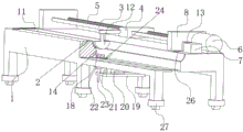
FIG. 1 is a schematic diagram of the structure of the present invention;
FIG. 2 is a side view of the present invention;
fig. 3 is a partial cross-sectional view of the present invention.
The reference numerals are represented as follows: 1. a measuring station; 2. a placement groove; 3. a guide rail; 4. a slide block; 5. a screw rod; 6. a first motor; 7. a computer; 8. a support plate; 9. a baffle; 10. a pressure sensor; 11. an abutting plate; 12. a moving plate; 13. a timer; 14. a moving groove; 15. a moving beam; 16. a positioning groove; 17. a limiting block; 18. a movable plate; 19. a mounting plate; 20. a second motor; 21. a riser; 22. a rotating lever; 23. a push rod; 24. a notch; 25. a buffer layer; 26. a level gauge; 27. and a universal wheel.
Detailed Description
For the purpose of making apparent the objects, technical solutions and advantages of the present invention, the present invention will be further described in detail with reference to the following examples and the accompanying drawings, wherein the exemplary embodiments of the present invention and the descriptions thereof are for illustrating the present invention only and are not to be construed as limiting the present invention. It should be noted that the present invention is already in a practical development and use stage.
Example 1
Referring to fig. 1, an anchor rod detection system comprises a measuring table 1 with a cuboid overall shape, wherein a placing groove 2 for placing an anchor rod is formed in the measuring table 1 along the length direction of the measuring table 1; the measuring table 1 is provided with a guide rail 3, a slide block 4, a screw rod 5, a first motor 6 and a computer 7, the measuring table 1 on one side of the placing groove 2 is provided with 2 support plates 8 which are parallel to each other, the screw rod 5 is rotationally connected to the 2 support plates 8 through bearings, one end of the screw rod 5 passes through the corresponding support plate 8 and is coaxially connected with an output shaft of the first motor 6, the first motor 6 is arranged on the measuring table 1 through bolts, the guide rail 3 is welded between the 2 support plates 8, the guide rail 3 and the screw rod 5 are parallel to the length direction of the placing groove 2, the slide block 4 is sleeved on the screw rod 5, the slide block 4 is in threaded fit with the screw rod 5, and the guide rail 3 passes through the slide block 4 and is in sliding fit with the slide block 4; the standing groove 2 is kept away from the one end of first motor 6 and is provided with baffle 9, one side that baffle 9 is close to first motor 6 is provided with pressure sensor 10, one side that pressure sensor 10 deviates from baffle 9 is provided with butt plate 11, the welding has movable plate 12 on the slider 4, movable plate 12 extends to in the standing groove 2, movable plate 12's shape can be with the shape assorted of standing groove 2, movable plate 12 is used for the cooperation butt plate 11 to carry out the centre gripping to the stock, first motor 6 electricity is connected with time-recorder 13, pressure sensor 10 and time-recorder 13 all with computer 7 electric connection, the centre gripping plate face of movable plate 12 is laminated with the centre gripping face of butt plate 11 when the butt plate 11 is nearest.
Referring to fig. 1, when the detection system is used to measure the length of the anchor rod, firstly, the anchor rod is placed in the placing groove 2 of the measuring table 1, the first motor 6 is started, at the moment when the first motor 6 is started, the timer 13 starts timing, the first motor 6 drives the screw rod 5 to rotate on the supporting plate 8, because the sliding block 4 is in threaded fit with the screw rod 5, and the sliding block 4 is sleeved on the guide rail 3 and is in sliding fit with the guide rail 3, the sliding block 4 drives the moving plate 12 to move along the guide rail 3 towards the direction close to the anchor rod, then the moving plate 12 pushes the anchor rod to move towards the direction close to the abutting plate 11, after the anchor rod abuts against the abutting plate 11, the pressure sensor 10 monitors the pressure value to rise, when the pressure value reaches the preset value, the pressure sensor 10 transmits a signal to the computer 7, the computer 7 controls the first motor 6 to stop running, and simultaneously the timer 13 stops timing, the timer 13 transmits the running time of the first motor 6 to the computer 7, the maximum stroke of the movable plate 12 is known, the farthest distance between the movable plate 12 and the abutting plate 11 is equal to the maximum stroke of the movable plate 12, the moving speed of the sliding block 4 and the movable plate 12 is also known, the farthest distance between the movable plate 12 and the abutting plate 11 is prestored in the computer 7, the moving speed of the movable plate 12 is prestored in the computer 7, the computer 7 integrates the maximum distance between the movable plate 12 and the abutting plate 11, the moving speed of the movable plate 12 and the moving time of the movable plate 12, the length of the anchor rod can be calculated, the computer 7 is electrically connected with a display, the length data of the anchor rod is directly displayed through the display, the measuring personnel can directly read through the display, the manual reading operation is reduced, the accuracy of measuring the length of the anchor rod is improved, and the step of aligning one end of the anchor rod with the zero scale of the measuring tool is reduced, and the convenience of system use is improved.
Referring to fig. 1 and 2, as a preferred embodiment, a moving groove 14 is formed in the inner bottom wall of the placing groove 2 along the length direction of the placing groove 2, a baffle 9 blocks the same ends of the placing groove 2 and the moving groove 14 at the same time, a moving beam 15 is placed in the moving groove 14, the moving beam 15 can move in the moving groove 14 along the length direction of the moving groove 14, a positioning groove 16 is formed in the top wall of the moving beam 15 along the length direction of the moving beam 15, the cross section of the positioning groove 16 can be rectangular or inverted triangle, the opening part of the positioning groove 16 is used for placing an anchor rod, the purpose is to rapidly place the anchor rod at a designated position of the moving beam 15, and the position of the anchor rod is limited to a certain extent through the positioning groove 16, so that the condition that the position of the anchor rod is deviated in the process of pushing the anchor rod by the moving plate 12 to perform length measurement is reduced, and accurate measurement of the length of the anchor rod is facilitated; the bottom of the movable beam 15 is also provided with a plurality of rollers, when the movable plate 12 pushes the anchor rod, static friction force between the anchor rod and the movable beam 15 drives the movable beam 15 to move along with the anchor rod, and the movable beam 15 moves through the rollers, so that abrasion caused by relative sliding between the anchor rod and the movable beam 15 is reduced; it should be noted that the length of the movable beam 15 is shorter than the length of a conventional anchor rod, so that both ends of the anchor rod extend beyond the movable beam 15, and the anchor rod is conveniently clamped by the movable plate 12 and the abutting plate 11.
Referring to fig. 1 and 2, as a preferred embodiment, a movable plate 18 is disposed on an inner bottom wall of a movable groove 14, one end of the movable plate 18 away from a baffle plate 9 is connected with a measuring table 1 through a hinge, a movable beam 15, the baffle plate 9, a pressure sensor 10 and an abutting plate 11 are all located above the movable plate 18, the movable beam 15 moves on the movable plate 18, a mounting plate 19 is welded on the measuring table 1 below the movable groove 14, a second motor 20 is mounted on the mounting plate 19 through bolts, an output shaft of the second motor 20 is horizontally disposed, a vertical plate 21 is welded on the mounting plate 19, a rotating rod 22 is rotatably connected on the vertical plate 21 through a bearing, the output shaft of the second motor 20 is connected with one end of the rotating rod 22 through a coupling, the rotating rod 22 is located below the movable groove 14, the different surfaces of the rotating rod 22 are perpendicular to the movable beam 15, a push rod 23 is welded on the rotating rod 22, the push rod 23 is perpendicular to the rotating rod 22, and in combination with fig. 3, notches 24 and 23 are formed on the bottom wall of the movable groove 14 and are located right below the notches 24; after the length measurement of the first anchor rod is finished, the second motor 20 is started, the second motor 20 rotates to drive the rotating rod 22 and the ejector rod 23 to rotate, the ejector rod 23 points to the movable plate 18 through the notch 24 in the rotating process of the ejector rod 23, the ejector rod 23 can jack up one end of the movable plate 18 close to the baffle 9, when the ejector rod 23 is vertically upwards, the second motor 20 stops running, at the moment, the movable plate 18 inclines, one side of the movable plate 18, which is far away from the baffle 9, is provided with the limiting block 17, the movable beam 15 moves towards the direction close to the limiting block 17 under the dead weight, when the movable beam 15 moves back to a proper position (the middle position between the current movable plate 12 and the abutting plate 11), the second motor 20 is started again to drive the ejector rod 23 to continuously rotate or reversely rotate, the ejector rod 23 leaves the notch 24, the movable plate 18 is downwards to the original horizontal position, the operation of manually moving the movable beam 15 to the proper position is reduced, at the moment, the second anchor rod (the length of the second anchor rod is shorter than that of the first anchor rod) can be placed on the positioning groove 16, the time of moving plate 12 is reset, the running length of the movable plate 12 is not needed, the running length of the anchor rod is detected, and the system is detected, and the length of the anchor is detected conveniently; if the longer anchor rod is required to be measured, the first motor 6 is required to be started to enable the movable plate 12 to move back to the initial position (the position of the movable plate 12 farthest from the abutting plate 11) along with the sliding block 4, and the second motor 20 is also required to be started to enable the movable beam 15 to move back to the middle position of the travel of the movable plate 12, so that the anchor rod to be measured can be conveniently placed; the second motor 20 can be a servo motor, and is started each time, the second motor 20 and the ejector rod 23 are started to rotate vertically downwards for half a turn when the second motor 20 and the ejector rod 23 are started to stop, the ejector rod 23 vertically upwards jacks up one end of the movable plate 18 at the moment, the second motor 20 is started again, the second motor 20 and the ejector rod 23 rotate for half a turn to return to the initial position, and the movable plate 18 is lowered to the horizontal position at the moment.
Referring to fig. 1, as a preferred embodiment, a plurality of rollers are provided on both side walls of the moving beam 15 in the length direction of the moving groove 14, the rollers not being shown in the drawings; when the moving beam 15 moves in the moving groove 14, the rollers at two sides of the moving beam 15 roll along the side wall of the moving groove 14, so that the resistance between the moving beam 15 and the side wall of the moving groove 14 is reduced, and the moving plate 12 is convenient to push the anchor rod to move along with the moving beam 15; the roller can adopt a silica gel wheel or a plastic wheel.
Referring to fig. 1 and 2, as a preferred embodiment, the inner wall of the placement groove 2 and the top wall of the moving beam 15 are both provided with inclined planes inclined towards the positioning groove 16, and the lowest point of the inclined planes of the placement groove 2 is higher than the lowest point of the inclined planes of the moving beam 15, and the inclined planes of the placement groove 2 and the inclined planes of the moving beam 15 can be arc surfaces, so that a measurer can conveniently place an anchor rod into the placement groove 2 and then automatically slide down to the positioning groove 16 along the arc surfaces. In other embodiments, the inclined surface may be a flat surface inclined toward the positioning slot 16, which also has the effect of facilitating the automatic sliding of the anchor rod onto the positioning slot 16.
Referring to fig. 2, as a preferred embodiment, the inclined surface of the placement groove 2 and the inclined surface of the moving beam 15 are both provided with a buffer layer 25, the buffer layer 25 comprises rubber, the rubber is adhered to the inclined surface, and when the anchor rod is placed in the placement groove 2, the rubber can play a role in buffering the anchor rod, so that collision and abrasion of the measuring table 1 and the moving beam 15 on the anchor rod are reduced. In other embodiments, the buffer layer 25 may also be cloth, plastic.
Referring to fig. 1, as a preferred embodiment, 2 levels 26 are further provided on the top wall of the measuring table 1, the 2 levels 26 are located at the diagonal positions of the measuring table 1, and universal wheels 27 are further provided at the bottom of the measuring table 1, so that the measuring table 1 can be conveniently moved on the horizontal ground by the levels 26.
The foregoing description of the embodiments has been provided for the purpose of illustrating the general principles of the invention, and is not meant to limit the scope of the invention, but to limit the invention to the particular embodiments, and any modifications, equivalents, improvements, etc. that fall within the spirit and principles of the invention are intended to be included within the scope of the invention.
Claims (6)
1. An anchor rod detection system comprises a cuboid measuring table (1), and is characterized in that: a placing groove (2) for placing an anchor rod is formed in the measuring table (1) along the length direction of the measuring table (1); the measuring table (1) is provided with a guide rail (3), a sliding block (4), a screw rod (5), a first motor (6) and a computer (7), the guide rail (3) and the screw rod (5) are parallel to the length direction of the placing groove (2), the screw rod (5) is rotatably arranged on the measuring table (1), the first motor (6) is positioned at one end of the measuring table (1) and is coaxially connected with one end of the screw rod (5), the sliding block (4) is arranged on the screw rod (5) and is in threaded fit with the screw rod (5), and the guide rail (3) penetrates through the sliding block (4) to be in sliding fit with the sliding block (4); be provided with movable plate (12) on slider (4), movable plate (12) extend to in standing groove (2), the one end of standing groove (2) is provided with baffle (9), one side that baffle (9) are close to movable plate (12) is provided with pressure sensor (10), one side that pressure sensor (10) deviate from baffle (9) is provided with butt plate (11), movable plate (12) are used for cooperating butt plate (11) to carry out the centre gripping to the stock, first motor (6) electricity is connected with time-recorder (13), pressure sensor (10), first motor (6) and time-recorder (13) all with computer (7) electric connection, the grip block face of movable plate (12) is laminated mutually with the grip block face of butt plate (11) when butt plate (11) are nearest.
2. A rock bolt detection system according to claim 1, wherein: the movable support is characterized in that a movable groove (14) is formed in the inner bottom wall of the placing groove (2) along the length direction of the placing groove (2), a movable beam (15) is arranged in the movable groove (14), a positioning groove (16) used for limiting the position of an anchor rod is formed in the upper portion of the movable beam (15) along the length direction of the placing groove (2), and a plurality of rollers are arranged at the bottom of the movable beam (15).
3. A rock bolt detection system according to claim 2, wherein: the movable plate (18) is arranged on the inner bottom wall of the movable groove (14), one end of the movable plate (18) away from the baffle plate (9) is hinged with the measuring table (1), a second motor (20) is arranged on the measuring table (1) below the movable groove (14), an output shaft of the second motor (20) is coaxially connected with a rotating rod (22), a push rod (23) is arranged on the rotating rod (22), a notch (24) for the push rod (23) to periodically pass through due to rotation is formed in the inner bottom wall of the movable groove (14), and the push rod (23) is used for pushing up one end of the movable plate (18) close to the baffle plate (9) after passing through the notch (24); one side of the movable plate (18) deviating from the baffle plate (9) is provided with a limiting block (17), and the limiting block (17) is used for limiting the movable beam (15) in the stroke of the movable plate (12).
4. A rock bolt detection system according to claim 2, wherein: and a plurality of rollers are arranged on two side walls of the moving beam (15) along the length direction of the moving groove (14).
5. A rock bolt detection system according to claim 2, wherein: the inner wall of the placing groove (2) and the top wall of the moving beam (15) are respectively provided with an inclined surface inclined towards the positioning groove (16), and the lowest point of the inclined surface of the placing groove (2) is higher than the highest point of the inclined surface on the moving beam (15).
6. A rock bolt detection system according to claim 5, wherein: buffer layers (25) are arranged on the inclined planes of the placing grooves (2) and the inclined planes of the moving beams (15).
Priority Applications (1)
| Application Number | Priority Date | Filing Date | Title |
|---|---|---|---|
| CN202310364562.3A CN116086377B (en) | 2023-04-07 | 2023-04-07 | Anchor rod detection system |
Applications Claiming Priority (1)
| Application Number | Priority Date | Filing Date | Title |
|---|---|---|---|
| CN202310364562.3A CN116086377B (en) | 2023-04-07 | 2023-04-07 | Anchor rod detection system |
Publications (2)
| Publication Number | Publication Date |
|---|---|
| CN116086377A CN116086377A (en) | 2023-05-09 |
| CN116086377B true CN116086377B (en) | 2023-06-09 |
Family
ID=86204857
Family Applications (1)
| Application Number | Title | Priority Date | Filing Date |
|---|---|---|---|
| CN202310364562.3A Active CN116086377B (en) | 2023-04-07 | 2023-04-07 | Anchor rod detection system |
Country Status (1)
| Country | Link |
|---|---|
| CN (1) | CN116086377B (en) |
Citations (16)
| Publication number | Priority date | Publication date | Assignee | Title |
|---|---|---|---|---|
| GB1137014A (en) * | 1967-06-17 | 1968-12-18 | Standard Internat Corp | Automatic feeding apparatus |
| SU1590221A1 (en) * | 1988-03-14 | 1990-09-07 | Смоленское Научно-Производственное Объединение "Техноприбор" | Arrangement for cutting pipes |
| WO2002052220A2 (en) * | 2000-12-22 | 2002-07-04 | Dr. Johannes Heidenhain Gmbh | Device for measuring length |
| JP2005283318A (en) * | 2004-03-30 | 2005-10-13 | Kansai Electric Power Co Inc:The | Filled conduit depth measurement system |
| CN202033019U (en) * | 2011-04-08 | 2011-11-09 | 泉州运城制版有限公司 | Asynchronously length measuring equipment |
| CN107764188A (en) * | 2017-09-20 | 2018-03-06 | 杭州慧翔电液技术开发有限公司 | A kind of silicon single crystal rod length and gradient detection means and its detection method |
| CN210089653U (en) * | 2019-04-23 | 2020-02-18 | 盐城恒发精密齿轮有限公司 | Tool for rapidly detecting length of worm |
| CN210293282U (en) * | 2019-07-03 | 2020-04-10 | 苏州速安世智能装备有限公司 | Screw rod measuring mechanism |
| CN111189421A (en) * | 2020-03-31 | 2020-05-22 | 张则君 | Length detection device and detection method for cylindrical pin |
| CN212779002U (en) * | 2020-08-27 | 2021-03-23 | 武汉鹰革精密科技有限公司 | Length measuring mechanism of length checking and confirming machine |
| CN212903113U (en) * | 2020-10-13 | 2021-04-06 | 南通海林汽车橡塑制品有限公司 | Sunroof drain pipe length measurement device |
| CN213579242U (en) * | 2020-10-15 | 2021-06-29 | 重庆中烟工业有限责任公司 | Cigarette length testing device |
| CN213932426U (en) * | 2020-08-13 | 2021-08-10 | 太仓市恒博金属制品有限公司 | Water explodes joint length measurement tool |
| CN113446973A (en) * | 2021-06-29 | 2021-09-28 | 西南交通大学 | Prestress transfer length measuring method and device and electronic equipment |
| CN215572569U (en) * | 2021-04-21 | 2022-01-18 | 无锡仪腾精密仪器有限公司 | Connecting rod final inspection SPC measuring device of SPC comprehensive detection workstation |
| CN115325367A (en) * | 2022-10-12 | 2022-11-11 | 四川省公路规划勘察设计研究院有限公司 | Monitoring device for dangerous running state of vehicles on highway |
-
2023
- 2023-04-07 CN CN202310364562.3A patent/CN116086377B/en active Active
Patent Citations (16)
| Publication number | Priority date | Publication date | Assignee | Title |
|---|---|---|---|---|
| GB1137014A (en) * | 1967-06-17 | 1968-12-18 | Standard Internat Corp | Automatic feeding apparatus |
| SU1590221A1 (en) * | 1988-03-14 | 1990-09-07 | Смоленское Научно-Производственное Объединение "Техноприбор" | Arrangement for cutting pipes |
| WO2002052220A2 (en) * | 2000-12-22 | 2002-07-04 | Dr. Johannes Heidenhain Gmbh | Device for measuring length |
| JP2005283318A (en) * | 2004-03-30 | 2005-10-13 | Kansai Electric Power Co Inc:The | Filled conduit depth measurement system |
| CN202033019U (en) * | 2011-04-08 | 2011-11-09 | 泉州运城制版有限公司 | Asynchronously length measuring equipment |
| CN107764188A (en) * | 2017-09-20 | 2018-03-06 | 杭州慧翔电液技术开发有限公司 | A kind of silicon single crystal rod length and gradient detection means and its detection method |
| CN210089653U (en) * | 2019-04-23 | 2020-02-18 | 盐城恒发精密齿轮有限公司 | Tool for rapidly detecting length of worm |
| CN210293282U (en) * | 2019-07-03 | 2020-04-10 | 苏州速安世智能装备有限公司 | Screw rod measuring mechanism |
| CN111189421A (en) * | 2020-03-31 | 2020-05-22 | 张则君 | Length detection device and detection method for cylindrical pin |
| CN213932426U (en) * | 2020-08-13 | 2021-08-10 | 太仓市恒博金属制品有限公司 | Water explodes joint length measurement tool |
| CN212779002U (en) * | 2020-08-27 | 2021-03-23 | 武汉鹰革精密科技有限公司 | Length measuring mechanism of length checking and confirming machine |
| CN212903113U (en) * | 2020-10-13 | 2021-04-06 | 南通海林汽车橡塑制品有限公司 | Sunroof drain pipe length measurement device |
| CN213579242U (en) * | 2020-10-15 | 2021-06-29 | 重庆中烟工业有限责任公司 | Cigarette length testing device |
| CN215572569U (en) * | 2021-04-21 | 2022-01-18 | 无锡仪腾精密仪器有限公司 | Connecting rod final inspection SPC measuring device of SPC comprehensive detection workstation |
| CN113446973A (en) * | 2021-06-29 | 2021-09-28 | 西南交通大学 | Prestress transfer length measuring method and device and electronic equipment |
| CN115325367A (en) * | 2022-10-12 | 2022-11-11 | 四川省公路规划勘察设计研究院有限公司 | Monitoring device for dangerous running state of vehicles on highway |
Also Published As
| Publication number | Publication date |
|---|---|
| CN116086377A (en) | 2023-05-09 |
Similar Documents
| Publication | Publication Date | Title |
|---|---|---|
| CN214470889U (en) | Building engineering straightness detection device that hangs down | |
| CN102840980A (en) | Comprehensive accuracy and performance testing device of rolling linear guide pair | |
| CN107607077A (en) | Building ground measurement method of planeness | |
| CN104390609A (en) | Automatic online steel rail straightness measuring instrument | |
| CN116086377B (en) | Anchor rod detection system | |
| CN111351724A (en) | Device and method for testing shock resistance of reflective film | |
| CN210400238U (en) | Online thickness detection device for lithium battery pole piece | |
| CN107607078A (en) | Building ground roughness detection equipments | |
| CN112252139A (en) | Highway bridge flatness detection equipment | |
| CN219137330U (en) | Highway road surface width detection device | |
| CN218994273U (en) | Concrete type airport runway flatness monitoring device | |
| CN214039906U (en) | House floor thickness tester | |
| CN213021484U (en) | Building wall surface detection equipment | |
| CN115014255A (en) | Detection device for bridge expansion joint | |
| CN115325967A (en) | Flatness detection device for building | |
| CN212895812U (en) | Road construction width range unit | |
| CN111089541A (en) | Scanning mechanism of laser thickness gauge | |
| CN111521504A (en) | High-strength ceramic roller wear-resistance detection device | |
| CN219867047U (en) | Crack detection device for constructional engineering | |
| CN219624702U (en) | Rock climbing fulcrum abrasion detection device | |
| CN216410121U (en) | Measuring device suitable for casting blank | |
| CN214502945U (en) | Thickness detection equipment for engineering supervision | |
| CN220018530U (en) | Building straightness detection device that hangs down | |
| CN213645380U (en) | A interval measuring device for aluminum plate roll | |
| CN211444631U (en) | Elevator rope detection device |
Legal Events
| Date | Code | Title | Description |
|---|---|---|---|
| PB01 | Publication | ||
| PB01 | Publication | ||
| SE01 | Entry into force of request for substantive examination | ||
| SE01 | Entry into force of request for substantive examination | ||
| GR01 | Patent grant | ||
| GR01 | Patent grant |