CN116042378B - Streptococcus suis type 2 virulence gene detection kit and detection method thereof - Google Patents
Streptococcus suis type 2 virulence gene detection kit and detection method thereof Download PDFInfo
- Publication number
- CN116042378B CN116042378B CN202310316206.4A CN202310316206A CN116042378B CN 116042378 B CN116042378 B CN 116042378B CN 202310316206 A CN202310316206 A CN 202310316206A CN 116042378 B CN116042378 B CN 116042378B
- Authority
- CN
- China
- Prior art keywords
- groove
- limiting
- extrusion pad
- supporting seat
- shaped
- Prior art date
- Legal status (The legal status is an assumption and is not a legal conclusion. Google has not performed a legal analysis and makes no representation as to the accuracy of the status listed.)
- Active
Links
Images

Classifications
-
- B—PERFORMING OPERATIONS; TRANSPORTING
- B65—CONVEYING; PACKING; STORING; HANDLING THIN OR FILAMENTARY MATERIAL
- B65D—CONTAINERS FOR STORAGE OR TRANSPORT OF ARTICLES OR MATERIALS, e.g. BAGS, BARRELS, BOTTLES, BOXES, CANS, CARTONS, CRATES, DRUMS, JARS, TANKS, HOPPERS, FORWARDING CONTAINERS; ACCESSORIES, CLOSURES, OR FITTINGS THEREFOR; PACKAGING ELEMENTS; PACKAGES
- B65D25/00—Details of other kinds or types of rigid or semi-rigid containers
- B65D25/02—Internal fittings
- B65D25/10—Devices to locate articles in containers
-
- C—CHEMISTRY; METALLURGY
- C12—BIOCHEMISTRY; BEER; SPIRITS; WINE; VINEGAR; MICROBIOLOGY; ENZYMOLOGY; MUTATION OR GENETIC ENGINEERING
- C12Q—MEASURING OR TESTING PROCESSES INVOLVING ENZYMES, NUCLEIC ACIDS OR MICROORGANISMS; COMPOSITIONS OR TEST PAPERS THEREFOR; PROCESSES OF PREPARING SUCH COMPOSITIONS; CONDITION-RESPONSIVE CONTROL IN MICROBIOLOGICAL OR ENZYMOLOGICAL PROCESSES
- C12Q1/00—Measuring or testing processes involving enzymes, nucleic acids or microorganisms; Compositions therefor; Processes of preparing such compositions
- C12Q1/68—Measuring or testing processes involving enzymes, nucleic acids or microorganisms; Compositions therefor; Processes of preparing such compositions involving nucleic acids
- C12Q1/6844—Nucleic acid amplification reactions
- C12Q1/686—Polymerase chain reaction [PCR]
-
- C—CHEMISTRY; METALLURGY
- C12—BIOCHEMISTRY; BEER; SPIRITS; WINE; VINEGAR; MICROBIOLOGY; ENZYMOLOGY; MUTATION OR GENETIC ENGINEERING
- C12Q—MEASURING OR TESTING PROCESSES INVOLVING ENZYMES, NUCLEIC ACIDS OR MICROORGANISMS; COMPOSITIONS OR TEST PAPERS THEREFOR; PROCESSES OF PREPARING SUCH COMPOSITIONS; CONDITION-RESPONSIVE CONTROL IN MICROBIOLOGICAL OR ENZYMOLOGICAL PROCESSES
- C12Q1/00—Measuring or testing processes involving enzymes, nucleic acids or microorganisms; Compositions therefor; Processes of preparing such compositions
- C12Q1/68—Measuring or testing processes involving enzymes, nucleic acids or microorganisms; Compositions therefor; Processes of preparing such compositions involving nucleic acids
- C12Q1/6876—Nucleic acid products used in the analysis of nucleic acids, e.g. primers or probes
- C12Q1/6888—Nucleic acid products used in the analysis of nucleic acids, e.g. primers or probes for detection or identification of organisms
- C12Q1/689—Nucleic acid products used in the analysis of nucleic acids, e.g. primers or probes for detection or identification of organisms for bacteria
-
- C—CHEMISTRY; METALLURGY
- C12—BIOCHEMISTRY; BEER; SPIRITS; WINE; VINEGAR; MICROBIOLOGY; ENZYMOLOGY; MUTATION OR GENETIC ENGINEERING
- C12R—INDEXING SCHEME ASSOCIATED WITH SUBCLASSES C12C - C12Q, RELATING TO MICROORGANISMS
- C12R2001/00—Microorganisms ; Processes using microorganisms
- C12R2001/01—Bacteria or Actinomycetales ; using bacteria or Actinomycetales
- C12R2001/46—Streptococcus ; Enterococcus; Lactococcus
-
- Y—GENERAL TAGGING OF NEW TECHNOLOGICAL DEVELOPMENTS; GENERAL TAGGING OF CROSS-SECTIONAL TECHNOLOGIES SPANNING OVER SEVERAL SECTIONS OF THE IPC; TECHNICAL SUBJECTS COVERED BY FORMER USPC CROSS-REFERENCE ART COLLECTIONS [XRACs] AND DIGESTS
- Y02—TECHNOLOGIES OR APPLICATIONS FOR MITIGATION OR ADAPTATION AGAINST CLIMATE CHANGE
- Y02A—TECHNOLOGIES FOR ADAPTATION TO CLIMATE CHANGE
- Y02A50/00—TECHNOLOGIES FOR ADAPTATION TO CLIMATE CHANGE in human health protection, e.g. against extreme weather
- Y02A50/30—Against vector-borne diseases, e.g. mosquito-borne, fly-borne, tick-borne or waterborne diseases whose impact is exacerbated by climate change
Landscapes
- Chemical & Material Sciences (AREA)
- Life Sciences & Earth Sciences (AREA)
- Organic Chemistry (AREA)
- Proteomics, Peptides & Aminoacids (AREA)
- Engineering & Computer Science (AREA)
- Zoology (AREA)
- Analytical Chemistry (AREA)
- Wood Science & Technology (AREA)
- Health & Medical Sciences (AREA)
- Immunology (AREA)
- Biochemistry (AREA)
- Microbiology (AREA)
- Molecular Biology (AREA)
- Biotechnology (AREA)
- Biophysics (AREA)
- Chemical Kinetics & Catalysis (AREA)
- Physics & Mathematics (AREA)
- Bioinformatics & Cheminformatics (AREA)
- General Engineering & Computer Science (AREA)
- General Health & Medical Sciences (AREA)
- Genetics & Genomics (AREA)
- Mechanical Engineering (AREA)
- Investigating Or Analysing Biological Materials (AREA)
Abstract
The invention relates to the technical field of reagent boxes, in particular to a streptococcus suis type 2 virulence gene detection reagent box and a detection method thereof, the reagent box comprises a reagent box body, a revolving door is rotatably connected to the top of the reagent box body, an object storage groove for containing reagent materials is formed in the inner cavity of the top of the reagent box body, a T-shaped groove is formed in the inner cavity of the bottom of the reagent box body, a supporting seat is slidably connected in the T-shaped groove, when a gun head stretches into a test tube, the conical shape of the gun head contacts a V-shaped part, then the gun head slides on a second extrusion pad through a first extrusion pad, and meanwhile, an elastic potential energy is released through a compression spring, so that a command plate is driven to stretch out of a first limiting cylinder, a worker can conveniently check the command plate, whether the corresponding test tube is input with liquid or not, and the problem of excessive or missed liquid on a micropore shelf is prevented in the later stage in the process of inputting liquid can be judged through the command plate.
Description
Technical Field
The invention relates to the technical field of kits, in particular to a streptococcus suis type 2 virulence gene detection kit and a detection method thereof.
Background
The streptococcus suis disease is an important zoonotic disease, clinical symptoms of pigs after the disease are mainly characterized by meningitis, septicemia and arthritis, the existing streptococcus suis type 2 virulence gene detection kit adopts a double antibody sandwich method enzyme-linked immunosorbent assay, negative control, positive control, a sample and an HRP marked detection antibody are sequentially added into coated micropores which are pre-coated with streptococcus suis type 2 capture antibodies, then TMB is used for developing, TMB is converted into blue under the catalysis of peroxidase and is converted into final yellow under the action of acid, and then an enzyme marker instrument is used for measuring absorbance to judge whether the samples contain streptococcus suis.
In the process of carrying out a large amount of extraction experiments on streptococcus suis, the problems exist in the use process of the streptococcus suis type 2 virulence gene detection kit: the staff inputs samples or standard substances into the micropores on the corresponding cloth plate numbers according to a certain sequence, the two holes of the samples and the standard substances are parallel, and then the liquid is input into the micropores by using the pipettor, but the traditional micropore plates are transparent, the staff needs to input various liquids into the micropores one by one with different numbers, and the staff needs to seal the covers of the micropores and replace gun heads on the pipettor due to the large number of the micropores and frequent liquid input by the staff, so that the attention of the staff is reduced, the next liquid input error is easily caused, and the situation of excessive or missed addition of the micropore liquid on the micropore frame is caused; secondly, in the micropore that the staff utilized the manual liquid with the liquid of pipettor inside to add, long-time operation can not make the rifle head keep at the bottom of micropore vertical, leads to the liquid adhesion of rifle head on the lateral wall in the micropore easily, leads to liquid splash outside even, and then causes liquid pollution and extravagant, reduces the accuracy of experimental quality.
Disclosure of Invention
Therefore, the invention aims to provide a streptococcus suis type 2 virulence gene detection kit and a detection method thereof, which effectively solve the problems of liquid pollution and waste caused by the situation that liquid is input into micropores and is added or not added in the micropores and the liquid at the gun head is output from the side wall of the micropores.
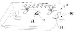
In order to achieve the above purpose, the present invention provides the following technical solutions: the utility model provides a streptococcus suis type 2 virulence gene detection kit, includes SS-2 PCR reaction tube, SS-2 primer probe tube, SS-2 negative control tube, SS-2 positive control tube, SS-2 quantitative standard substance pipe, still includes the kit body, the top of kit body rotates and is connected with the revolving door, the storage groove that is used for placing reagent material has been seted up to the top inner chamber of kit body, T type groove has been seted up to the bottom inner chamber of kit body, sliding connection has the supporting seat in the T type groove, the inner chamber slip of supporting seat is equipped with the micropore shelf, the top of supporting seat is rectangular array and installs a plurality of first spacing drums, the left side wall of first spacing drum is provided with instruction subassembly, the top of first spacing drum is provided with the spacing subassembly that is used for carrying out spacing to the rifle head, the left and right sides of supporting seat is provided with the subassembly that is used for taking out the micropore shelf, the front end bottom of supporting seat is provided with supporting subassembly.
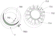
Preferably, the instruction subassembly includes V type spare, the notch has been seted up to the left side wall of first spacing drum, the V type spare is inboard to be rotated and is connected at the notch, arc frame is installed to the front side of V type spare, the fixing base is installed to the rear side bottom of V type spare, the bottom of fixing base is provided with first extrusion pad, the diapire of notch corresponds one side of first extrusion pad and is provided with the second extrusion pad that is inconsistent with first extrusion pad, the mounting panel is installed to the front end of fixing base, the instruction board is installed to one side that the fixing base was kept away from to the mounting panel, the accessory board is installed to the roof of notch, be connected with compression spring between the front end of accessory board and V type spare.
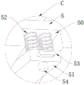
Preferably, the square groove has been seted up to the below that just is located the second extrusion pad of first spacing drum inner chamber, the front end bottom threaded connection of first spacing drum has the screw rod, the screw rod stretches into the inside in square groove and installs first conical gear, the roof rotation in square groove is connected with the second conical gear with first conical gear engaged with, the below sliding connection that first spacing drum is located the notch has the nut with second extrusion pad fixed connection, the lead screw with nut threaded connection is installed at the top of second conical gear, the second extrusion pad is located the front and back both sides of lead screw and installs the second gag lever post that stretches into square inslot portion, the internally mounted of fixing base has a plurality of spring telescopic links with first extrusion pad fixed connection.
Preferably, the inclined plate which is inclined is arranged on one side, far away from the first limiting cylinder, of the auxiliary plate, a spring rod is connected to one end, far away from the first limiting cylinder, of the inclined plate in a sliding mode, a pressing plate used for driving the auxiliary plate to return is arranged at the bottom of the spring rod, and vertical pressing plates are arranged at the tops of the plurality of spring rods which are arranged vertically.
Preferably, the dead lever that is rectangular array is installed at the top of supporting seat, the outside cover of dead lever is equipped with expansion spring, be located two dead lever tops sliding connection that transversely lay and have horizontal press board, horizontal press board extrudees on the top of vertical press board.
Preferably, the spacing subassembly includes the lift drum of threaded connection at first spacing drum top, a plurality of F type supports that are annular array are installed at the top of lift drum, and a plurality of two horizontal ends of F type support are installed and are used for spacing second spacing drum to the rifle head, the top of lift drum just is located between the adjacent F type support and installs digital spacing marker.
Preferably, two movable grooves are formed in the bottom of the front end of the supporting seat, the bottoms of the two movable grooves are rotationally connected with a rotating block, two connecting springs fixedly connected with the rotating block are installed in the two movable grooves, a pressing plate is installed at the front end of the rotating block, a first limiting rod is installed at the bottom of the front end of the rotating block, and a hole groove matched with the first limiting rod is formed in one side, corresponding to the first limiting rod, of the bottom of the front end of the kit body.
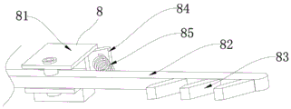
Preferably, the taking out assembly includes two slides of sliding connection in T type inslot, two the slide sets up respectively in the left and right sides symmetry of supporting seat, the inside rotation of slide is connected with and takes out the frame, the front end of taking out the frame stretches out in the outside of supporting seat, the rear end of taking out the frame stretches into T type inslot and installs three and take out the piece, three take out the piece and keep away from one side of taking out the frame and hug closely on the micropore shelf, the reset plate that is the slope is installed to the rear end of slide, be connected with first reset spring between reset plate and the taking out the frame.
Preferably, the supporting component includes the supporting legs, two T type storage tanks have been seted up to the front end bottom of supporting seat, two the inside in T type storage tanks rotates and is connected with the supporting legs, two install the connection pivot between the supporting legs, the linkage groove has been seted up to the bottom of supporting seat and be located between two T type storage tanks, the one end of connecting the pivot passes inside the linkage groove and installs drive gear, the inboard in linkage groove is connected with the rack board with drive gear engaged with through the slide rail connected mode, be connected with second reset spring between the front end in rack board and the preceding lateral wall in linkage groove, first finger drive plate is installed to the rear end of rack board.
In addition, the invention also provides a detection method of the streptococcus suis type 2 virulence gene detection kit, which comprises the following specific steps:
s1: firstly, sliding the supporting seat out of the outside, automatically opening the supporting feet and standing on the workbench;
s2: placing the microporous frame on the supporting seat, and sliding the supporting seat out of the T-shaped groove again;
s3: when the gun head stretches into the bottommost part of the test tube, the instruction board stretches out of the first limit cylinder, so that a worker can check the gun head;
s4: when the friction force of the first extrusion pad and the second extrusion pad gradually decreases, the adjusting screw rod drives the second extrusion pad to lift until the friction force is enough for the V-shaped piece to return;
s5: the height between the lifting cylinder and the first limiting cylinder is adjusted until the outlet end of the gun head stretches into the bottommost part of the test tube, so that the gun head is kept vertical to the test tube under the limiting action of the two second limiting cylinders;
s6: when needs take out fast to the micropore shelf, through the relative pulling of taking out the shelf on both sides, take out the middle part of shelf and rotate in the slide, then three on both sides take out the piece and suppress the micropore shelf, later the staff can be manual take out the shelf and take out outside, later take out to the micropore shelf can.
Compared with the prior art, the invention has the beneficial effects that:
(1) According to the invention, when the gun head stretches into the test tube, the conical shape of the gun head touches the V-shaped piece, then the gun head slides on the second extrusion pad through the first extrusion pad, and meanwhile, the compression spring releases elastic potential energy, so that the command plate is driven to stretch out of the first limit cylinder, a worker can conveniently check the command plate, and can judge whether the corresponding test tube is filled with liquid or not through the command plate, so that errors can be avoided in the liquid filling process in the later period, and the occurrence of excessive addition and missed addition of liquid on the microporous shelf can be reduced.
(2) According to the invention, the height between the lifting cylinder and the first limiting cylinder is adjusted, so that the outlet end of the gun head extends into the bottommost part of the test tube, the gun head is kept vertical to the test tube under the limiting action of the two second limiting cylinders, the liquid of the gun head is prevented from adhering to the side wall in the micropore, and even the liquid is splashed out of the outside.
(3) According to the invention, under the mutual matching of the screw rod, the first conical gear, the second conical gear, the screw rod and the screw cap, the friction force between the second extrusion pad and the first extrusion pad is favorably adjusted, and the spring telescopic rod is further arranged, so that the impact force of the second extrusion pad on the first extrusion pad is reduced, and the service lives of the second extrusion pad and the second extrusion pad are prolonged.
(4) The invention is also beneficial to the quick taking out of the microporous frame by the staff through arranging the taking-out component, and meanwhile, the invention is beneficial to improving the clamping force of the taking-out block on the microporous frame by arranging the reset plate and the first reset spring so as to be convenient for quick taking out of the microporous frame, and is beneficial to the clamping stability of the microporous frame so as to be convenient for the stability of placing the test tube.
Drawings
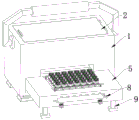
FIG. 1 is a schematic diagram of the overall structure of the present invention;
FIG. 2 is an exploded view of the overall structure of the present invention;
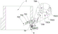
FIG. 3 is a longitudinal cross-sectional view of a first spacing cylinder of the present invention;
FIG. 4 is an enlarged view of a portion of FIG. 2A;
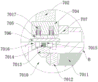
FIG. 5 is an enlarged view of a portion of B in FIG. 3;
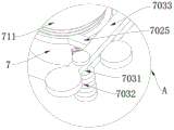
FIG. 6 is an exploded view of the first spacing cylinder and lifting cylinder of the present invention;
FIG. 7 is another angular schematic view of the support base of the present invention;
FIG. 8 is an enlarged view of a portion of C in FIG. 7;
FIG. 9 is a schematic view of a take-out assembly of the present invention;
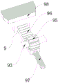
fig. 10 is a schematic view of a support assembly according to the present invention.
In the figure:
1. a kit body;
2. a revolving door;
3. a storage tank;
4. a T-shaped groove;
5. a support base; 50. a movable groove; 51. a rotating block; 52. a connecting spring; 53. pressing the plate; 54. a first stop lever;
6. a microporous scaffold;
7. a first limit cylinder; 70. an instruction component; 701. a notch; 702. a V-shaped member; 703. an arc-shaped frame; 704. a fixing seat; 705. a first squeeze pad; 706. a second squeeze pad; 707. a mounting plate; 708. an auxiliary plate; 709. a compression spring; 7010. a square groove; 7011. a screw; 7012. a first bevel gear; 7013. a second bevel gear; 7014. a screw rod; 7015. a screw cap; 7016. a second limit rod; 7017. a spring telescoping rod; 7021. an instruction board; 7022. an inclined plate; 7023. a spring rod; 7024. a pressing plate; 7025. a vertical pressing plate; 7031. a fixed rod; 7032. an expansion spring; 7033. a transverse pressing plate; 71. a limit component; 711. a lifting cylinder; 712. an F-shaped support; 713. a second limit cylinder; 714. digital limit markers;
8. taking out the assembly; 81. a slide; 82. taking out the frame; 83. taking out the block; 84. a reset plate; 85. a first return spring;
9. a support assembly; 91. a T-shaped storage groove; 92. supporting feet; 93. the connecting rotating shaft; 94. a linkage groove; 95. a drive gear; 96. rack plate; 97. a second return spring; 98. a first finger drive plate.
Detailed Description
The following description of the embodiments of the present invention will be made clearly and completely with reference to the accompanying drawings, in which it is apparent that the embodiments described are only some embodiments of the present invention, but not all embodiments. All other embodiments, which can be made by those skilled in the art based on the embodiments of the invention without making any inventive effort, are intended to be within the scope of the invention.
Example 1
As shown in figures 1-3, the streptococcus suis type 2 virulence gene detection kit comprises an SS-2 PCR reaction tube, an SS-2 primer probe tube, an SS-2 negative control tube, an SS-2 positive control tube and an SS-2 quantitative standard tube, and further comprises a kit body 1, wherein the top of the kit body 1 is rotationally connected with a revolving door 2, a storage groove 3 for placing reagent materials is formed in the top inner cavity of the kit body 1, a T-shaped groove 4 is formed in the bottom inner cavity of the kit body 1, a test tube groove in a linear array is formed in the top of the T-shaped groove 4, a supporting seat 5 is slidably connected in the T-shaped groove 4, a microporous frame 6 is slidably arranged in the inner cavity of the supporting seat 5, a plurality of first limiting cylinders 7 are mounted on the top of the supporting seat 5 in a rectangular array, the left side wall of first spacing drum 7 is provided with command subassembly 70, command subassembly 70 includes V type spare 702, notch 701 has been seted up to the left side wall of first spacing drum 7, V type spare 702 is rotated in notch 701 inboard and is connected, arc frame 703 is installed to the front side of V type spare 702, fixing base 704 is installed to the rear side bottom of V type spare 702, the bottom of fixing base 704 is provided with first extrusion pad 705, the diapire of notch 701 corresponds one side of first extrusion pad 705 and is provided with the second extrusion pad 706 that contradicts with first extrusion pad 705, mounting panel 707 is installed to the front end of fixing base 704, command board 7021 is installed to one side that mounting panel 707 kept away from fixing base 704, auxiliary plate 708 is installed to the roof of notch 701, be connected with compression spring 709 between the front end of auxiliary plate 708 and V type spare 702.
During operation, open revolving door 2 and take out the reagent material of holding inslot 3 from holding inslot 3, then take out supporting seat 5 in reagent box body 1 bottom, afterwards, the staff is with test tube one by one on micropore shelf 6, then put into supporting seat 5 inside with micropore shelf 6, simultaneously the test tube stretches into along the test tube inslot, guarantee the vertical spacing of test tube, then the staff is when inputting liquid on the test tube, insert in first spacing drum 7 through the rifle head, because the longitudinal section of rifle head is the toper form setting, therefore the bottom of rifle head can not contact with arc frame 703 in inserting first spacing drum 7 inboard, but with the rifle head continues to stretch into the time of test tube, the top extrusion arc frame 703 of rifle head, make arc frame drive fixing base 704 and first extrusion pad 705 slide from second extrusion pad 706, simultaneously compression spring 709 release elastic potential energy, and then drive mounting panel 707 and command board 7021 take place to rotate, in the liquid process when the staff is input, can be according to command board 7021's instruction, just can know whether corresponding command board 7021 is input liquid, thereby can be had more than the input liquid in the corresponding liquid through the time frame 7021, can be had more than the input liquid in the liquid can appear in the step of decreasing the input stage of mistake in the input liquid is more than the liquid is judged to the frame 706.
Notably, the command board 7021 is set to be red or other attractive colors, so that a worker can pay more attention to indication conveniently, and the arc-shaped frame 703 is made of rubber materials, so that friction force between the arc-shaped frame 703 and a gun head is increased conveniently.
Example two
The technical scheme is basically the same as that of the embodiment, and the difference is that, as shown in fig. 3-5, square grooves 7010 are formed in the inner cavity of the first limiting cylinder 7 and below the second extrusion pad 706, screws 7011 are connected to the bottom of the front end of the first limiting cylinder 7 in a threaded manner, the screws 7011 extend into the square grooves 7010 and are provided with first conical gears 7012, a second conical gear 7013 meshed with the first conical gears 7012 is rotatably connected to the top wall of the square grooves 7010, a nut 7015 fixedly connected with the second extrusion pad 706 is slidably connected to the first limiting cylinder 7 below the notch 701, a screw rod 7014 in threaded connection with the nut 7015 is mounted at the top of the second conical gear 7013, second limiting rods 7016 extending into the square grooves 7010 are mounted on the front side and the rear side of the screw rod 7014, a plurality of spring expansion rods 7017 fixedly connected with the first extrusion pad 705 are mounted inside the fixing base 704, a second conical plate 7022 which is engaged with the first conical gear 7012 is rotatably connected to the top wall of the square grooves 7010, a plurality of spring plates 7022 which are inclined plates 7023 are mounted on the side of the auxiliary plates 7023 are rotatably connected to the first extrusion pad 7012, a plurality of spring plates 7023 are fixedly connected to the top plates 7031, and a plurality of spring plates 7023 are fixedly arranged on the top of the spring plates 7023, and the top plates are fixedly arranged on the top of the top plates of the support plates 7023, and the top plates of the top plates are fixedly arranged on the top of the side of the support the top plates of the support plates 7023 and the top of the support the top plates of the support plates 7023.
When the device is in operation, when the first extrusion pad 705 is continuously rubbed against the second extrusion pad 706 for a long time, the friction force between the first extrusion pad 705 and the second extrusion pad 706 is reduced, a worker can twist the screw 7011, then drive the first taper gear 7012 and the second taper gear 7013 to mutually rotate through the screw 7011, under the continuous movement of the second taper gear 7013, the nut 7015 is lifted along the top of the screw 7014, further, the second extrusion pad 706 is close to the first extrusion pad 705 under the limit of the second limiting rod 7016, the friction force between the first extrusion pad 705 and the second extrusion pad 706 is increased, so that the V-shaped piece 702 can work normally, when the V-shaped piece 702 returns, the worker can directly press the command plate 7021, then the command plate 7021 drives the mounting plate 707 and the fixing seat 704 to stretch into the notch 701, and then the spring inside the spring expansion rod 7017 enters a compressed state in the sliding process of the side wall of the second extrusion pad 706, so that the second extrusion pad 706 is convenient to reduce the impact force of the second extrusion pad 706, and the service life of the second extrusion pad 706 is prolonged.
In order to reduce the fatigue of a worker pressing the command plate 7021, the vertical pressing plate 7025 can drive the plurality of vertical spring rods 7023 to synchronously move downwards, and the two hands of the worker can press the two lateral pressing plates 7033, so that the expansion springs 7032 enter a compressed state, the whole vertical pressing plate 7025 of the lateral pressing plates 7033 moves downwards, and then the expansion springs 7032 release elastic potential energy, so that the aim of pressing the whole vertical pressing plate 7025 is fulfilled, and the vertical pressing device can synchronously press one command plate 7021 or a plurality of vertical command plates 7021 and synchronously press the whole command plate 7021, thereby reducing the pressing labor intensity of the worker on the command plate 7021.
Example III
The difference is that, as shown in fig. 3-5, a limiting component 71 for limiting the gun head is disposed at the top of the first limiting cylinder 7, the limiting component 71 includes a lifting cylinder 711 screwed on the top of the first limiting cylinder 7, a plurality of F-shaped supporting members 712 in an annular array are mounted at the top of the lifting cylinder 711, a second limiting cylinder 713 for limiting the gun head is mounted at two horizontal ends of the plurality of F-shaped supporting members 712, and a digital limiting marker 714 is mounted between the adjacent F-shaped supporting members 712 at the top of the lifting cylinder 711.
During operation, a worker can twist the lifting cylinder 711 to stretch and move along the top of the first limiting cylinder 7, and the length between the lifting cylinder 711 and the first limiting cylinder 7 is adjusted according to the length of the gun head until the outlet end of the gun head stretches into the bottommost part of the test tube, so that the gun head is beneficial to keeping the gun head vertical to the test tube under the limiting action of the two second limiting cylinders 713, the liquid of the gun head is prevented from adhering to the side wall in the micropore, and even the liquid splashes outside.
It is noted that the present invention can twist the height of the lifting cylinder 711 according to the digital limit markers 714, so that the operator can adjust the entire lifting cylinder 711 according to the digital mark, thereby improving the accuracy of the height of the entire lifting cylinder 711.
Example IV
The difference with the technical scheme of the first embodiment is that as shown in fig. 7-8, two movable grooves 50 are provided at the bottom of the front end of the supporting seat 5, the bottoms of the two movable grooves 50 are rotatably connected with a rotating block 51, two connecting springs 52 fixedly connected with the rotating block 51 are installed in the two movable grooves 50, a pressing plate 53 is installed at the front end of the rotating block 51, a first limiting rod 54 is installed at the bottom of the front end of the rotating block 51, and a hole groove matched with the first limiting rod 54 is provided at one side of the bottom of the front end of the kit body 1 corresponding to the first limiting rod 54.
When the experiment is finished, the staff drives the supporting seat 5 to stretch into inside the T-shaped groove 4, then the rotating block 51 gradually stretches into inside the movable groove 50 in the inside of the T-shaped groove 4, the connecting spring 52 enters the compression spring, then the staff presses the pressing plate 53 to drive the first limiting rod 54 to continue to stretch into the movable groove 50, the first limiting rod 54 completely stretches into the hole groove in the reagent box body 1, the supporting seat 5 is prevented from being separated from the reagent box body 1, and the supporting seat 5 is convenient to store in the reagent box body 1.
Example five
The technical scheme is basically the same as that of the first embodiment, except that, as shown in fig. 2 and 9, the left and right sides of the supporting seat 5 are provided with a taking-out assembly 8 for taking out the microporous frame 6, the taking-out assembly 8 includes two sliding seats 81 slidingly connected at the inner side of the T-shaped groove 4, the two sliding seats 81 are respectively arranged at the left and right sides of the supporting seat 5 and symmetrical, the inner part of the sliding seat 81 is rotationally connected with a taking-out frame 82, the front end of the taking-out frame 82 extends out of the supporting seat 5, the rear end of the taking-out frame 82 extends into the inner side of the T-shaped groove 4 and is provided with three taking-out blocks 83, one side of the three taking-out blocks 83 far from the taking-out frame 82 is clung to the microporous frame 6, the rear end of the sliding seat 81 is provided with an inclined reset plate 84, and a first reset spring 85 is connected between the reset plate 84 and the taking-out frame 82.
During operation, when needs take out fast to micropore shelf 6, through the relative pulling of taking out frame 82 on both sides, take out the middle part of frame 82 and rotate in slide 81, then the three piece 83 of taking out on both sides suppresses micropore shelf 6, later the staff can be manual take out the outside with taking out frame 82, later take out to micropore shelf 6 can.
It should be noted that, by providing the reset plate 84 and the first reset spring 85, the present invention is beneficial to improving the clamping force of the withdrawing block 83 on the micro-hole rack 6, so as to facilitate quick withdrawing of the micro-hole rack 6, and is beneficial to clamping stability of the micro-hole rack 6, so as to facilitate stability of placing test tubes.
Example six
The difference is that, as shown in fig. 7 and 10, the front end bottom of the supporting seat 5 is provided with a supporting component 9, the supporting component 9 includes supporting legs 92, two T-shaped receiving slots 91 are provided at the front end bottom of the supporting seat 5, the supporting legs 92 are rotatably connected in the two T-shaped receiving slots 91, a connecting shaft 93 is installed between the two supporting legs 92, a linkage slot 94 is provided at the bottom of the supporting seat 5 and between the two T-shaped receiving slots 91, one end of the connecting shaft 93 passes through the inside of the linkage slot 94 and is provided with a driving gear 95, the inner side of the linkage slot 94 is connected with a rack plate 96 meshed with the driving gear 95 in a sliding rail connection manner, a second reset spring 97 is connected between the front end of the rack plate 96 and the front side wall of the linkage slot 94, and a first finger driving plate 98 is installed at the rear end of the rack plate 96.
When the support seat 5 slides outside, the second reset spring 97 releases elastic potential energy and then drives the connecting rotating shaft 93 to rotate, then the support legs 92 extend out of the T-shaped storage groove 91 under the pressure of the connecting rotating shaft 93, so that the two support legs 92 support the support seat 5, the placement balance and stability of the microporous frame 6 are guaranteed, when the support seat 5 is driven to extend into the T-shaped groove 4, only the support legs 92 on two sides extend into the T-shaped storage groove 91, then the support legs 92 directly extend into the reagent box body 1.
The specific modes of use of the SS-2 PCR reaction tube, the SS-2 primer probe tube, the SS-2 negative control tube, the SS-2 positive control tube and the SS-2 quantitative standard tube are referred to by the application number 202110285406.9.
In addition, the invention also provides a detection method of the streptococcus suis type 2 virulence gene detection kit, which comprises the following specific steps:
s1: firstly, when the support seat 5 slides outside, the second return spring 97 releases elastic potential energy and then drives the connecting rotating shaft 93 to rotate, then the support legs 92 extend out of the T-shaped storage groove 91 under the pressure of the connecting rotating shaft 93, so that the two support legs 92 support the support seat 5, the placement balance and stability of the microporous frame 6 are ensured, when the support seat 5 is driven to extend into the T-shaped groove 4, only the support legs 92 on two sides need to extend into the T-shaped storage groove 91, and then the support legs 92 directly extend into the reagent kit body 1;
s2: secondly, opening the revolving door 2 to take out the reagent materials in the storage tank 3 from the storage tank 3, taking out the supporting seat 5 at the bottom of the reagent kit body 1, arranging test tubes on the micro-pore shelves 6 one by a worker, putting the micro-pore shelves 6 into the supporting seat 5, and extending the supporting seat 5 into the T-shaped tank 4;
s3: when a worker inputs liquid on a test tube, the worker inserts the gun head into the first limiting cylinder 7, the longitudinal section of the gun head is in a conical shape, so that the bottom of the gun head is not contacted with the arc-shaped frame 703 when being inserted into the first limiting cylinder 7, but as the gun head continues to extend into the test tube, the top of the gun head presses the arc-shaped frame 703, so that the arc-shaped frame 703 drives the fixed seat 704 and the first pressing pad 705 to slide from the second pressing pad 706, and meanwhile, the compression spring 709 releases elastic potential energy, and further drives the mounting plate 707 and the command plate 7021 to rotate;
s4: when the first extrusion pad 705 continuously rubs against the second extrusion pad 706 for a long time, the friction force between the first extrusion pad 705 and the second extrusion pad 706 is reduced, a worker can twist the screw 7011, then the first taper gear 7012 and the second taper gear 7013 are driven to mutually rotate by the screw 7011, under the continuous motion of the second taper gear 7013, the nut 7015 is lifted along the top of the screw 7014, and then the second extrusion pad 706 is close to the first extrusion pad 705 under the limit of the second limiting rod 7016, so that the friction force between the first extrusion pad 705 and the second extrusion pad 706 is increased, the V-shaped piece 702 can work normally, when the V-shaped piece 702 is returned, the worker can directly press the command plate 7021, then the command plate 7021 drives the mounting plate 707 and the fixing seat 704 to stretch into the notch 701, and then the spring inside the spring telescopic rod 7017 enters a compressed state in the sliding process of the side wall of the second extrusion pad 706, so that the impact force of the second extrusion pad 706 to the first extrusion pad 706 is reduced;
s5: the staff can twist the lifting cylinder 711 to stretch and move along the top of the first limiting cylinder 7, and the length between the lifting cylinder 711 and the first limiting cylinder 7 is adjusted according to the length of the gun head until the outlet end of the gun head stretches into the bottommost part of the test tube, so that the gun head is kept vertical to the test tube under the limiting action of the two second limiting cylinders 713;
s6: when the microporous frame 6 needs to be quickly taken out, the taking-out frames 82 on two sides are pulled relatively, the middle part of the taking-out frame 82 rotates in the sliding seat 81, then three taking-out blocks 83 on two sides press the microporous frame 6, then a worker can manually take out the taking-out frame 82, and then take out the microporous frame 6.
In the present specification, each embodiment is described in a progressive manner, and each embodiment is mainly described in a different point from other embodiments, and identical and similar parts between the embodiments are all enough to refer to each other.
The previous description of the disclosed embodiments is provided to enable any person skilled in the art to make or use the present invention. Various modifications to these embodiments will be readily apparent to those skilled in the art, and the generic principles defined herein may be applied to other embodiments without departing from the spirit or scope of the invention. Thus, the present invention is not intended to be limited to the embodiments shown herein but is to be accorded the widest scope consistent with the principles and novel features disclosed herein.
Claims (7)
1. The utility model provides a streptococcus suis type 2 virulence gene detection kit, includes SS-2 PCR reaction tube, SS-2 primer probe tube, SS-2 negative control pipe, SS-2 positive control pipe, SS-2 quantitative standard substance pipe, its characterized in that: the kit comprises a kit body (1), wherein a rotating door (2) is rotationally connected to the top of the kit body (1), a storage groove (3) for accommodating reagent materials is formed in the top inner cavity of the kit body (1), a T-shaped groove (4) is formed in the bottom inner cavity of the kit body (1), a supporting seat (5) is slidably connected in the T-shaped groove (4), a micropore rack (6) is slidably arranged in the inner cavity of the supporting seat (5), a plurality of first limiting cylinders (7) are arranged at the top of the supporting seat (5) in a rectangular array, an instruction component (70) is arranged on the left side wall of each first limiting cylinder (7), a limiting component (71) for limiting a gun head is arranged at the top of each first limiting cylinder, a taking-out component (8) for taking out the micropore rack (6) is arranged on the left side and the right side of the supporting seat (5), and a supporting component (9) is arranged at the bottom of the front end of the supporting seat (5).
The command assembly (70) comprises a V-shaped part (702), a notch (701) is formed in the left side wall of the first limiting cylinder (7), the V-shaped part (702) is connected with the inner side of the notch (701) in a rotating mode, an arc-shaped frame (703) is arranged on the front side of the V-shaped part (702), a fixing seat (704) is arranged at the bottom of the rear side of the V-shaped part (702), a first extrusion pad (705) is arranged at the bottom of the fixing seat (704), a second extrusion pad (706) which is in contact with the first extrusion pad (705) is arranged on one side of the bottom wall of the notch (701) corresponding to the first extrusion pad (705), a mounting plate (707) is arranged at the front end of the fixing seat (704), a command plate (7021) is arranged on one side, far away from the fixing seat (704), an auxiliary plate (708) is arranged on the top wall of the notch (701), and a compression spring (709) is connected between the auxiliary plate (708) and the front end of the V-shaped part (702);
the limiting assembly (71) comprises a lifting cylinder (711) which is connected to the top of the first limiting cylinder (7) in a threaded mode, a plurality of F-shaped supporting pieces (712) which are arranged in an annular array are arranged at the top of the lifting cylinder (711), second limiting cylinders (713) used for limiting the gun head are arranged at two horizontal ends of the F-shaped supporting pieces (712), and digital limiting markers (714) are arranged at the top of the lifting cylinder (711) and between the adjacent F-shaped supporting pieces (712).
2. The streptococcus suis type 2 virulence gene detection kit of claim 1, wherein: the utility model discloses a spring compression device, including first spacing drum (7), second extrusion pad (706), screw rod (7011) is offered to the below of first spacing drum (7) inner chamber and being located second extrusion pad (706), screw rod (7011) is offered to the front end bottom threaded connection of first spacing drum (7), screw rod (7011) stretches into the inside of square groove (7010) and installs first bevel gear (7012), the roof rotation of square groove (7010) is connected with second bevel gear (7013) with first bevel gear (7012) engaged with, first spacing drum (7) are located below of notch (701) sliding connection have nut (7015) with second extrusion pad (706) fixed connection, screw rod (7014) with nut (7015) threaded connection is installed at the top of second bevel gear (7013), second extrusion pad (706) are located the front and back both sides of screw rod (7014) and install second spacing pole (7016) that stretches into inside square groove (7010), the internally mounted of fixing base (704) has a plurality of flexible spring compression bars (7017) with first extrusion pad (7017) fixed connection.
3. The streptococcus suis type 2 virulence gene detection kit of claim 2, wherein: one side that supplementary board (708) kept away from first spacing drum (7) is installed and is inclined board (7022), the one end sliding connection that first spacing drum (7) was kept away from to inclined board (7022) has spring pole (7023), pressboard (7024) that are used for driving supplementary board (708) return are installed to the bottom of spring pole (7023), are located a plurality of that vertical laid spring pole (7023) top is installed vertical pressing board (7025).
4. A streptococcus suis type 2 virulence gene test kit according to claim 3, wherein: the top of supporting seat (5) is installed and is dead lever (7031) that rectangular array was equipped with expansion spring (7032) in the outside cover of dead lever (7031), is located two dead lever (7031) top sliding connection that transversely lay have horizontal pressing board (7033), horizontal pressing board (7033) extrudees on the top of vertical pressing board (7025).
5. The streptococcus suis type 2 virulence gene detection kit of claim 4, wherein: two movable grooves (50) are formed in the bottom of the front end of the supporting seat (5), a rotating block (51) is rotatably connected to the bottom of each movable groove (50), two connecting springs (52) fixedly connected with the rotating block (51) are installed in each movable groove (50), a pressing plate (53) is installed at the front end of each rotating block (51), a first limiting rod (54) is installed at the bottom of the front end of each rotating block (51), and a hole groove matched with the corresponding first limiting rod (54) is formed in one side, corresponding to the corresponding first limiting rod (54), of the bottom of the front end of the kit body (1).
6. The streptococcus suis type 2 virulence gene detection kit of claim 1, wherein: the utility model provides a take out subassembly (8) including sliding connection at two slide (81) of T type groove (4) inboard, two slide (81) set up respectively in the left and right sides symmetry of supporting seat (5), the inside rotation of slide (81) is connected with takes out frame (82), the front end of taking out frame (82) stretches out in the outside of supporting seat (5), the rear end of taking out frame (82) stretches into T type groove (4) inboard and installs three and take out piece (83), three take out piece (83) keep away from one side of taking out frame (82) and hug closely on micropore shelf (6), reset plate (84) that is the slope is installed to the rear end of slide (81), be connected with first reset spring (85) between reset plate (84) and take out frame (82).
7. The streptococcus suis type 2 virulence gene detection kit of claim 6, wherein: the support assembly (9) comprises support legs (92), two T-shaped storage grooves (91) are formed in the bottom of the front end of the support base (5), the two T-shaped storage grooves (91) are connected with the support legs (92) in a rotating mode, a connecting rotating shaft (93) is installed between the support legs (92), a linkage groove (94) is formed in the bottom of the support base (5) and between the two T-shaped storage grooves (91), one end of the connecting rotating shaft (93) penetrates through the inside of the linkage groove (94) and is provided with a driving gear (95), a rack plate (96) meshed with the driving gear (95) is connected to the inner side of the linkage groove (94) in a sliding rail connection mode, a second reset spring (97) is connected between the front end of the rack plate (96) and the front side wall of the linkage groove (94), and a first finger driving plate (98) is installed at the rear end of the rack plate (96).
Priority Applications (1)
| Application Number | Priority Date | Filing Date | Title |
|---|---|---|---|
| CN202310316206.4A CN116042378B (en) | 2023-03-29 | 2023-03-29 | Streptococcus suis type 2 virulence gene detection kit and detection method thereof |
Applications Claiming Priority (1)
| Application Number | Priority Date | Filing Date | Title |
|---|---|---|---|
| CN202310316206.4A CN116042378B (en) | 2023-03-29 | 2023-03-29 | Streptococcus suis type 2 virulence gene detection kit and detection method thereof |
Publications (2)
| Publication Number | Publication Date |
|---|---|
| CN116042378A CN116042378A (en) | 2023-05-02 |
| CN116042378B true CN116042378B (en) | 2023-06-23 |
Family
ID=86133540
Family Applications (1)
| Application Number | Title | Priority Date | Filing Date |
|---|---|---|---|
| CN202310316206.4A Active CN116042378B (en) | 2023-03-29 | 2023-03-29 | Streptococcus suis type 2 virulence gene detection kit and detection method thereof |
Country Status (1)
| Country | Link |
|---|---|
| CN (1) | CN116042378B (en) |
Families Citing this family (2)
| Publication number | Priority date | Publication date | Assignee | Title |
|---|---|---|---|---|
| CN116355744B (en) * | 2023-05-29 | 2023-09-12 | 哈尔滨瀚邦医疗科技有限公司 | Detection kit for synchronously detecting various porcine infectious disease viruses and application |
| CN116855368B (en) * | 2023-09-05 | 2023-11-21 | 哈尔滨瀚邦医疗科技有限公司 | Porcine-derived plasminogen determination kit and application thereof |
Citations (1)
| Publication number | Priority date | Publication date | Assignee | Title |
|---|---|---|---|---|
| CN112941211A (en) * | 2021-03-17 | 2021-06-11 | 哈尔滨瀚邦医疗科技有限公司 | Multiplex fluorescence quantitative PCR detection kit for streptococcus suis type 2 virulence genes and detection method thereof |
Family Cites Families (5)
| Publication number | Priority date | Publication date | Assignee | Title |
|---|---|---|---|---|
| CN109913371B (en) * | 2019-02-01 | 2020-04-10 | 南方医科大学珠江医院 | Three-dimensional poly-ball culture cavity mould |
| CN111733066A (en) * | 2019-09-29 | 2020-10-02 | 南京岚煜生物科技有限公司 | Integrated reagent cup for sample treatment and detection and method for detecting sample |
| CN111849742B (en) * | 2020-08-13 | 2024-07-09 | 江苏省人民医院(南京医科大学第一附属医院) | PCR sample adding platform and sample adding method thereof |
| WO2023041048A1 (en) * | 2021-09-17 | 2023-03-23 | 圣湘生物科技股份有限公司 | Automatic nucleic acid extraction device and nucleic acid extraction method therefor |
| CN216402278U (en) * | 2021-10-08 | 2022-04-29 | 上海佰仟里科技通信有限公司 | Quick detect reagent box of microorganism |
-
2023
- 2023-03-29 CN CN202310316206.4A patent/CN116042378B/en active Active
Patent Citations (1)
| Publication number | Priority date | Publication date | Assignee | Title |
|---|---|---|---|---|
| CN112941211A (en) * | 2021-03-17 | 2021-06-11 | 哈尔滨瀚邦医疗科技有限公司 | Multiplex fluorescence quantitative PCR detection kit for streptococcus suis type 2 virulence genes and detection method thereof |
Also Published As
| Publication number | Publication date |
|---|---|
| CN116042378A (en) | 2023-05-02 |
Similar Documents
| Publication | Publication Date | Title |
|---|---|---|
| CN116042378B (en) | Streptococcus suis type 2 virulence gene detection kit and detection method thereof | |
| CN217605538U (en) | Four-point bending fixture with pulling load | |
| CN206223541U (en) | A kind of liquid crystal display universal testing machine | |
| CN213423219U (en) | Sample adding gun | |
| CN220982670U (en) | Air spring pressure-resistant detection equipment | |
| CN212748124U (en) | Detection device is used in temperature sensor processing convenient to location | |
| CN219065094U (en) | Utensil is examined to passageway linking bridge in auto parts | |
| CN112643319A (en) | Assembling equipment for assembling automobile pipeline valve body structure and using method thereof | |
| CN217278397U (en) | Full-automatic analytical equipment is used in small-size ELISA adsorption test | |
| CN221252281U (en) | Anemia detection kit | |
| CN211235524U (en) | Sample introduction device of ultraviolet-visible spectrophotometer | |
| CN220019593U (en) | Gasoline sample detection device | |
| CN210051739U (en) | Alkali type burette for scientific research | |
| CN219447812U (en) | Protein S activity determination kit | |
| CN221445578U (en) | Smear device for medical clinical examination | |
| CN220835666U (en) | Immunodetection micropore board application of sample auxiliary device | |
| CN215140168U (en) | Kit storage tray | |
| CN213422736U (en) | Lifting and pressing type manual device for solid phase extraction instrument | |
| CN219707702U (en) | Contact-free detection kit | |
| CN219567530U (en) | Structure for synchronously pulling out plugs and collecting and adding reagents for multiple test tubes | |
| CN221485437U (en) | Dry blood spot analyzer | |
| CN219369551U (en) | Detection device for peroxide value content | |
| CN118190699B (en) | Moisture tester with self-cleaning structure | |
| CN217554515U (en) | Concatenation formula kit | |
| CN210604647U (en) | Concrete slump testing arrangement |
Legal Events
| Date | Code | Title | Description |
|---|---|---|---|
| PB01 | Publication | ||
| PB01 | Publication | ||
| SE01 | Entry into force of request for substantive examination | ||
| SE01 | Entry into force of request for substantive examination | ||
| GR01 | Patent grant | ||
| GR01 | Patent grant |