CN116033726B - Outdoor cabinet heat dissipation and dust removal system and control method - Google Patents
Outdoor cabinet heat dissipation and dust removal system and control method Download PDFInfo
- Publication number
- CN116033726B CN116033726B CN202310308059.6A CN202310308059A CN116033726B CN 116033726 B CN116033726 B CN 116033726B CN 202310308059 A CN202310308059 A CN 202310308059A CN 116033726 B CN116033726 B CN 116033726B
- Authority
- CN
- China
- Prior art keywords
- heat dissipation
- cabinet
- dust removal
- temperature parameter
- connecting plate
- Prior art date
- Legal status (The legal status is an assumption and is not a legal conclusion. Google has not performed a legal analysis and makes no representation as to the accuracy of the status listed.)
- Active
Links
Images

Classifications
-
- Y—GENERAL TAGGING OF NEW TECHNOLOGICAL DEVELOPMENTS; GENERAL TAGGING OF CROSS-SECTIONAL TECHNOLOGIES SPANNING OVER SEVERAL SECTIONS OF THE IPC; TECHNICAL SUBJECTS COVERED BY FORMER USPC CROSS-REFERENCE ART COLLECTIONS [XRACs] AND DIGESTS
- Y02—TECHNOLOGIES OR APPLICATIONS FOR MITIGATION OR ADAPTATION AGAINST CLIMATE CHANGE
- Y02D—CLIMATE CHANGE MITIGATION TECHNOLOGIES IN INFORMATION AND COMMUNICATION TECHNOLOGIES [ICT], I.E. INFORMATION AND COMMUNICATION TECHNOLOGIES AIMING AT THE REDUCTION OF THEIR OWN ENERGY USE
- Y02D10/00—Energy efficient computing, e.g. low power processors, power management or thermal management
Landscapes
- Cooling Or The Like Of Electrical Apparatus (AREA)
Abstract
The invention relates to the technical field of communication cabinets, in particular to a heat dissipation and dust removal system of an outdoor cabinet and a control method, wherein the heat dissipation and dust removal systemThe device comprises a heat dissipation and dust removal module, wherein the heat dissipation and dust removal module is used for adjusting a heat dissipation mode of the cabinet, the heat dissipation and dust removal module comprises a driving module and a flow guide module, the driving module is used for driving a heat dissipation medium to flow, and the flow guide module is used for changing the flow direction of the heat dissipation medium; the control method comprises when the first temperature parameter T 1 When the temperature exceeds a first preset value, the cabinet is adjusted to be in a first heat dissipation mode, and when a first temperature parameter T is 1 When the temperature exceeds a second preset value, the cabinet is adjusted to be in a second heat dissipation mode, and when a second temperature parameter T is adopted 2 And when the third preset value is exceeded, adjusting the cabinet to be in a second heat dissipation mode. According to the outdoor cabinet heat dissipation and dust removal system and the control method, the heat dissipation mode can be adjusted according to the temperature in the cabinet and the external temperature, so that the cabinet can be quickly cooled and the filter screen can be cleaned, and the normal operation of the cabinet is ensured.
Description
Technical Field
The invention relates to the technical field of computer communication, in particular to a heat dissipation and dust removal system of an outdoor cabinet and a control method.
Background
Power electronics operating in outdoor work are typically installed in cabinets. Because outdoor environment is abominable, the rack always needs to install active heat abstractor to guarantee the timely heat dissipation of power electronic device work in-process.
The communication cabinet is used for accommodating electric or electronic components in communication equipment, and is used as a casing for protection and support. In general, a cooling fan is disposed in a communication cabinet to reduce the temperature of an internal electric or electronic component, so as to ensure the normal operation of the electric or electronic component, and in order to ensure a larger cooling effect, cooling holes are generally formed in the side wall of the cabinet body. Meanwhile, due to the fact that the outdoor environment is complex, a filter screen is usually required to be arranged, but cleaning and dust removal are required after the filter screen is used for a long time.
Disclosure of Invention
Based on this, it is necessary to provide a heat dissipation and dust removal system and a control method for an outdoor cabinet, aiming at the problems existing in the existing communication cabinets.
The above purpose is achieved by the following technical scheme:
an outdoor cabinet heat dissipation and dust removal system, comprising:
the first acquisition module is used for acquiring a first temperature parameter T1 in the cabinet;
the second acquisition module is used for acquiring a second temperature parameter T2 of the environment outside the cabinet;
the heat dissipation and dust removal module is used for adjusting a heat dissipation mode of the cabinet according to the first temperature parameter T1 and the second temperature parameter T2;
the heat dissipation and dust removal module comprises a driving module and a flow guide module;
the driving module is used for driving the heat dissipation medium to flow;
the flow guiding module is used for changing the flow direction of the heat dissipation medium;
the driving module comprises a cooling fan, and the cooling fan is arranged inside the cabinet;
the heat dissipation and dust removal module further comprises a heat dissipation device, the heat dissipation device comprises a filter screen, a one-way bearing, a heat dissipation pipe, a first connecting plate, a second connecting plate, a wind shield, a piston block, an elastic piece, a water spraying pipe and a limiting sliding block, the filter screen can be rotatably arranged on the cabinet, one end of the filter screen is fixedly connected with the one-way bearing, the one-way bearing is arranged on a shaft of the heat dissipation fan, the heat dissipation fan drives the filter screen to rotate unidirectionally through the one-way bearing, the heat dissipation pipe is fixedly arranged inside the cabinet, one end of the first connecting plate is arranged on the heat dissipation pipe, the other end of the first connecting plate is arranged on the cabinet, the second connecting plate can be slidably arranged on the first connecting plate, the number of the first connecting plate and the second connecting plate is two, and the two groups of the first connecting plate and the second connecting plate are arranged at two ends of the heat dissipation pipe; a plurality of holes for air to pass through are formed in the first connecting plate and the second connecting plate; one end of the wind shield is hinged with the first connecting plate, and the other end of the wind shield is hinged with the second connecting plate; one end of the elastic piece is arranged on the cabinet, and the other end of the elastic piece is arranged on the piston block; one end of the piston block can be arranged on the second connecting plate in a sliding manner; the water spraying pipe is arranged on the piston block; the limit sliding block can be arranged on the cabinet in a sliding manner; one end of the piston block is abutted against the limit sliding block; when the rotating speed of the cooling fan reaches a set value, the piston block vertically moves downwards beyond the limit sliding block, and the water spraying pipe synchronously moves and is communicated with the cooling pipe.
The invention also provides a heat dissipation and dust removal control method of the outdoor cabinet, which is applied to the heat dissipation and dust removal system of the outdoor cabinet, and comprises the following steps:
step S100, a first temperature parameter T1 in a cabinet is obtained;
step S200, obtaining a second temperature parameter T2 outside the cabinet;
step S300, when the first temperature parameter T1 exceeds a first preset value, adjusting the cabinet to be in a first heat dissipation mode and continuing for a first preset time T1;
in the first heat dissipation mode, a heat dissipation medium in the cabinet flows according to a first flow path, and the heat dissipation medium has a first flow velocity V1;
step S310, when the first temperature parameter T1 exceeds a second preset value, adjusting the cabinet to a second heat dissipation mode and continuing for a second preset time T2;
step S400, when the second temperature parameter T2 exceeds a third preset value, adjusting the cabinet to the second heat dissipation mode and continuing for a third preset time T3;
in the second heat dissipation mode, a heat dissipation medium in the cabinet flows according to a second flow path, and the heat dissipation medium has a second flow velocity V2.
Further, after step S310, the method further includes:
step S320, when the first temperature parameter T1 exceeds the second preset value, starting an early warning prevention mode.
Further, the early warning prevention mode includes:
step S321, recording the execution times of step S310;
in step S322, in the fourth preset time t4, when the number of executions of step 310 exceeds the fourth preset value, an alarm is given.
Further, the first temperature parameter T1 at least includes a temperature of air in the cabinet.
Further, the second temperature parameter T2 includes at least a temperature of air of the environment outside the cabinet.
The beneficial effects of the invention are as follows:
the invention relates to a heat-dissipation and dust-removal system of an outdoor cabinet and a control method, wherein the heat-dissipation and dust-removal system comprises a heat-dissipation and dust-removal module, the heat-dissipation and dust-removal module is used for adjusting the heat-dissipation mode of the cabinet, the heat-dissipation and dust-removal module comprises a driving module and a flow guiding module, the driving module is used for driving a heat-dissipation medium to flow, and the flow guiding module is used for changing the flow direction of the heat-dissipation medium; the control method comprises the steps of adjusting the cabinet to be in a first heat dissipation mode when the first temperature parameter T1 exceeds a first preset value, adjusting the cabinet to be in a second heat dissipation mode when the first temperature parameter T1 exceeds a second preset value, and adjusting the cabinet to be in the second heat dissipation mode when the second temperature parameter T2 exceeds a third preset value. According to the outdoor cabinet heat dissipation and dust removal system and the control method, the heat dissipation mode can be adjusted according to the temperature in the cabinet and the external temperature, so that the cabinet can be quickly cooled and the filter screen can be cleaned, and the normal operation of the cabinet is ensured.
Drawings
Fig. 1 is a general flow chart of a heat dissipation and dust removal control method for an outdoor cabinet according to an embodiment of the present invention;
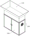
fig. 2 is a schematic perspective view of a heat dissipation and dust removal system for an outdoor cabinet according to an embodiment of the present invention;
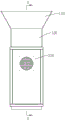
fig. 3 is a schematic right-view structural diagram of a heat dissipation and dust removal system for an outdoor cabinet according to an embodiment of the present invention;
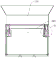
FIG. 4 is a cross-sectional view of the outdoor cabinet heat and dust removal system of FIG. 3 taken along the A-A direction;
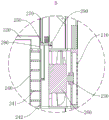
fig. 5 is a schematic diagram of a part B of the heat dissipation and dust removal system of the outdoor cabinet shown in fig. 4.
Wherein:
100. a collecting device; 110. a collection tank; 120. a storage bin; 130. a filtering port;
200. a heat sink; 210. a filter screen; 220. a heat radiating pipe; 230. a one-way bearing; 240. a first connection plate; 241. a wind deflector; 242. a second connecting plate; 250. a piston block; 260. a heat radiation fan; 270. a water spray pipe; 280. a water jet; 290. a limit sliding block;
300. and a cabinet.
Detailed Description
The present invention will be further described in detail below with reference to examples, which are provided to illustrate the objects, technical solutions and advantages of the present invention. It should be understood that the specific embodiments described herein are for purposes of illustration only and are not intended to limit the scope of the invention.
The numbering of components herein, such as "first," "second," etc., is used merely to distinguish between the described objects and does not have any sequential or technical meaning. The terms "coupled" and "connected," as used herein, are intended to encompass both direct and indirect coupling (coupling), unless otherwise indicated. In the description of the present invention, it should be understood that the terms "upper", "lower", "front", "rear", "left", "right", "vertical", "horizontal", "top", "bottom", "inner", "outer", "clockwise", "counterclockwise", etc. indicate orientations or positional relationships based on the orientations or positional relationships shown in the drawings, are merely for convenience in describing the present invention and simplifying the description, and do not indicate or imply that the device or element in question must have a specific orientation, be configured and operated in a specific orientation, and thus should not be construed as limiting the present invention.
In the present invention, unless expressly stated or limited otherwise, a first feature "up" or "down" a second feature may be the first and second features in direct contact, or the first and second features in indirect contact via an intervening medium. Moreover, a first feature being "above," "over" and "on" a second feature may be a first feature being directly above or obliquely above the second feature, or simply indicating that the first feature is level higher than the second feature. The first feature being "under", "below" and "beneath" the second feature may be the first feature being directly under or obliquely below the second feature, or simply indicating that the first feature is less level than the second feature.
According to the outdoor cabinet heat dissipation and dust removal system and the control method, the heat dissipation mode can be adjusted according to the temperature in the cabinet and the external temperature, the cabinet is rapidly cooled, and therefore normal operation of the cabinet is guaranteed.
Referring to fig. 1, fig. 1 is a general flow chart of a heat dissipation and dust removal control method for an outdoor cabinet according to an embodiment of the present invention, which may include:
step S100, a first temperature parameter T1 in a cabinet is obtained;
the first temperature parameter T1 includes at least a temperature of air in the cabinet.
Step S200, obtaining a second temperature parameter T2 outside the cabinet;
the second temperature parameter T2 comprises at least the temperature of the ambient air outside the cabinet.
Step S300, when the first temperature parameter T1 exceeds a first preset value, adjusting the cabinet to be in a first heat dissipation mode and continuing for a first preset time T1;
the first temperature parameters T1 in the cabinet are different in different areas and different in use conditions of communication mechanisms in different seasons; assuming that the first preset value is 40 ℃, when the first temperature parameter T1 in the cabinet is greater than 40 ℃, the cabinet is adjusted to be in the first heat dissipation mode and the first preset time T1 is continued.
In the first heat dissipation mode, the heat dissipation medium is air; under radiator fan's drive, flow according to first flow path, from left to right or from right to left flow promptly, the velocity of flow of air is V1, filters the back through the filter screen and cools down the rack inside, realizes the quick cooling to the rack to guarantee the normal operating of rack.
In step S310, when the first temperature parameter T1 exceeds a second preset value, the cabinet is adjusted to the second heat dissipation mode and the second preset time T2 is continued.
When the filter screen is blocked or the using power of the cabinet is higher or the external environment temperature is higher, the first temperature parameter T1 is abnormally increased, and the second preset value is assumed to be 60 ℃; when the first temperature parameter T1 exceeds 60 degrees celsius, the cabinet is adjusted to be in the second heat dissipation mode and the second preset time T2 is continued.
In the second heat dissipation mode, the heat dissipation medium is air and water; the air flows according to the second flow path under the drive of the cooling fan, namely flows from left to right or from right to left, and is filtered by the filter screen to cool the inside of the cabinet; the water is driven by air, so that the filter screen is cleaned when the temperature of the interior of the cabinet is reduced and the water is discharged; realize the quick cooling to the rack and wash cleanly to the filter screen to guarantee the normal operating of rack.
In step S400, when the second temperature parameter T2 exceeds a third preset value, the cabinet is adjusted to be in a second heat dissipation mode and the third preset time T3 is continued.
Communication mechanisms in different areas and seasons, wherein the second temperature parameters T2 outside the cabinet are different; assuming that the third preset value is 42 ℃, when the second temperature parameter T2 outside the cabinet is greater than 42 ℃, the cabinet is adjusted to be in the second heat dissipation mode and the third preset time T3 is continued.
It can be appreciated that when the first temperature parameter T1 in the cabinet is greater than the first preset value and the second temperature parameter T2 outside the cabinet is greater than the third preset value, it is necessary to adjust the cabinet to the second heat dissipation mode for the second preset time T2.
In the second heat dissipation mode, the heat dissipation medium is air and water; the air flows according to a second flow path under the drive of the cooling fan, namely flows from left to right or from right to left, the flow speed of the air is V2, V2 is larger than V1, and the air is filtered by a filter screen and then the inside of the cabinet is cooled; the water is driven by air, so that the filter screen is cleaned when the temperature of the interior of the cabinet is reduced and the water is discharged; realize the quick cooling to the rack and wash cleanly to the filter screen to guarantee the normal operating of rack.
It can be understood that, in the first heat dissipation mode or the second heat dissipation mode, when the first temperature parameter T1 is reduced to be smaller than the first preset value after the operation setting time, the heat dissipation fan on the cabinet can stop rotating or turn to low-speed operation, and the flow velocity of air is smaller than V1.
In another embodiment of the present invention, there is provided:
after step S310, further includes:
step S320, when the first temperature parameter T1 exceeds the second preset value, starting an early warning prevention mode.
The electronic equipment in the cabinet has certain requirements on the working environment temperature, and when the first temperature parameter T1 exceeds a second preset value, the electronic equipment in the cabinet is protected by starting an early warning and preventing mode.
In another embodiment of the present invention, the early warning prevention mode includes:
step S321, recording the execution times of step S310;
in step S322, in the fourth preset time t4, when the number of executions of step 310 exceeds the fourth preset value, an alarm is given.
Assuming that the fourth preset time t4 is one hour, the fourth preset value is 5; the cabinet is adjusted to be in the second heat radiation mode within one hour and the times of the third preset time t3 are more than 5, so that the condition that the electronic equipment in the cabinet works abnormally or the external environment temperature is high to cause overload operation of part of the electronic equipment, the heating is abnormal, the alarm is given at the moment, and the secondary injury is reduced is indicated.
In another embodiment of the present invention, an outdoor cabinet heat dissipation and dust removal system applied to the outdoor cabinet heat dissipation and dust removal control method at least includes:
the first acquisition module is used for acquiring a first temperature parameter T1 in the cabinet;
the second acquisition module is used for acquiring a second temperature parameter T2 of the environment outside the cabinet;
the heat dissipation and dust removal module is used for adjusting the heat dissipation mode of the cabinet;
the heat dissipation and dust removal module comprises a driving module and a flow guide module;
the driving module is used for driving the heat dissipation medium to flow;
the flow guiding module is used for changing the flow direction of the heat dissipation medium;
as shown in fig. 2 to 5, the first obtaining module is a temperature sensor disposed in the cabinet 300, and is configured to obtain a first temperature parameter T1 in the cabinet 300; the second obtaining module is a temperature sensor arranged outside the cabinet 300 and is used for obtaining a second temperature parameter T2 of the environment outside the cabinet 300; the heat dissipation and dust removal module is used for adjusting a heat dissipation mode of the cabinet 300; the heat dissipation and dust removal module comprises a heat dissipation device 200; the heat dissipation and dust removal module comprises a driving module and a flow guide module, wherein the driving module comprises a heat dissipation fan 260, and the flow guide module changes the flow direction of the heat dissipation fan 260 through electric control so as to change the flow direction of a heat dissipation medium.
The collecting device 100 is disposed right above the cabinet 300; the collection device 100 includes a collection tank 110, a storage bin 120, and a filter port 130; the collecting tank 110 is used for collecting rainwater and natural water; the storage bin 120 is used for storing rainwater and natural water, a liquid level meter is arranged in the storage bin 120, and the liquid level meter is used for measuring the liquid level in the storage bin 120; one end of the storage bin 120 is communicated with a water pipe through a valve; when the liquid level meter senses that the liquid level in the storage bin 120 is lower than a set value, the valve is opened to supplement tap water into the storage bin 120 until the liquid level meter senses that the liquid level in the storage bin 120 reaches the set value; the filtering port 130 is used to filter out leaves and dust contained in rainwater and natural water.
The number of the heat dissipation fans 260 is two, and the two heat dissipation fans 260 are oppositely arranged at two ends of the cabinet 300.
The number of the heat dissipating devices 200 is two, the heat dissipating devices 200 are arranged at two ends of the heat dissipating fan 260, and the two heat dissipating devices 200 are connected through the heat dissipating tube 220; the heat dissipating device 200 includes a filter 210, a one-way bearing 230, a first connection plate 240, a wind shield 241, a second connection plate 242, a piston block 250, an elastic member, a water spray pipe 270, a water spray outlet 280, and a limit slider 290, wherein the elastic member is a tension spring in this embodiment.
The filter screen 210 can be rotatably arranged on the side wall of the cabinet 300, the filter screen 210 is positioned at the outer side of the cooling fan 260, one end of the filter screen 210 is fixedly connected with the one-way bearing 230, the one-way bearing 230 is sleeved on the shaft of the cooling fan 260, the cooling fan 260 drives the filter screen 210 to rotate unidirectionally through the one-way bearing 230, and the filter screen 210 can be driven to rotate only when the cooling fan 260 blows air; the radiating pipe 220 spirals around the electronic device; one end of the first connection plate 240 is fixedly connected to the radiating pipe 220, and the other end is fixedly connected to the cabinet 300; one end of the radiating pipe 220 is communicated with a cavity formed by the first connecting plate 240 on the left side and the second connecting plate 242 on the left side, and the other end is communicated with a cavity formed by the first connecting plate 240 on the right side and the second connecting plate 242 on the right side; one end of the wind shield 241 is hinged with the first connecting plate 240, and the other end is hinged with the second connecting plate 242; the first connection plate 240 and the second connection plate 242 are provided with a plurality of holes for air to pass through; one end of the piston block 250 is connected with the cabinet 300 in a vertically sliding manner by a tension spring, and the other end is connected with the second connecting plate 242 in a left-right sliding manner; one end of the water spray pipe 270 is communicated with the filter outlet 130, and the other end is abutted against the piston block 250; the limit slide block 290 can be arranged in the cabinet 300 in a left-right sliding manner through a pressure spring, when the rotating speed of the cooling fan 260 reaches a set value, namely, when the flow speed of air is V2, the piston block 250 is driven to vertically move downwards beyond the limit slide block 290 under the action of internal and external pressure difference, and then the water spraying pipe 270 is communicated with the cooling pipe 220 through the water spraying port 280.
It will be appreciated that the heat exchange amount may be increased by providing a plurality of sets of water spray pipes 270, water spray ports 280 and heat radiating pipes 220.
It will be appreciated that a spray generator may be provided at the water jet 280, which turns into a mist of water as it passes through the spray generator, so that the water has a better heat absorbing effect.
It will be appreciated that when the rotational speed of the cooling fan 260 is such that the flow rate of air is V2, the piston block 250 may be directly driven to move by an electric cylinder or an air cylinder.
In combination with the above embodiment, the use principle and working process of the embodiment of the present invention are as follows:
in the first heat dissipation mode, assuming that the left heat dissipation fan 260 is blowing, the left heat dissipation fan 260 drives the left filter screen 210 to rotate, so that impurities adhered on the left filter screen 210 are thrown out, the right heat dissipation fan 260 is sucking air, then air enters from the right filter screen 210, exchanges heat with air in the cabinet 300, and is led out from the left filter screen 210, and the flow rate of the air is V1; assuming that the right cooling fan 260 is blowing, the right cooling fan 260 drives the right filter screen 210 to rotate, so that impurities adhered on the right filter screen 210 are thrown out, the left cooling fan 260 is sucking air, and air enters from the left filter screen 210 and is led out from the right filter screen 210 after exchanging heat with air in the cabinet 300, the flow rate of the air is V1, and the rapid cooling of the interior of the cabinet 300 is realized, so that the normal operation of the cabinet 300 is ensured.
Assuming that the left cooling fan 260 is blowing, the left cooling fan 260 drives the left filter screen 210 to rotate, so that impurities adhered on the left filter screen 210 are thrown out, the right cooling fan 260 is sucking air, and then air enters from the right filter screen 210, exchanges heat with air in the cabinet 300, and is led out from the left filter screen 210, the flow rate of the air is V1, and at the moment, dust is accumulated on the right filter screen 210.
When the first temperature parameter T1 exceeds the second preset value, which may be caused by the blockage of the filter screen 210, the cabinet 300 is adjusted to the second heat dissipation mode for a third preset time T3; the left cooling fan 260 is electrically controlled to suck air, the right cooling fan 260 is air blowing, the right cooling fan 260 drives the right filter screen 210 to rotate, impurities adhered on the right filter screen 210 are thrown out, meanwhile, the rotating speed of the cooling fan 260 is increased, the flow speed of air is V2, V2 is larger than V1, the air pressure above the piston block 250 is larger than the air pressure below the piston block 250, on one hand, the piston block 250 can vertically move downwards under the action of pressure difference by overcoming the friction force of the limit sliding block 290 and the pulling force of the tension spring, the second connecting plate 242 is driven by the wind shield 241 to vertically move downwards and simultaneously horizontally move leftwards, and then part of holes on the first connecting plate 240 are shielded through the wind shield 241, and at the moment, part of air passes through the holes on the first connecting plate 240 to exchange heat with the air in the cabinet 300; on the other hand, as the piston block 250 moves down, the water spray pipe 270 communicates with the radiating pipe 220 through the water spray ports 280; when the rotation speed of the heat radiation fan 260 makes the flow rate of air be V2, the piston block 250 may be directly driven to move by the electric cylinder or the air cylinder, thereby achieving the above effect; the water is impacted on the side wall of the radiating pipe 220 under the pushing of gravity and air to form water dew, or a spray generator is arranged at the water spraying port 280, when the water passes through the spray generator, the water becomes water mist, and then the heat in the cabinet 300 is absorbed through the radiating pipe 220 under the pushing of the air and the subsequent water, and then the water is impacted on the filter screen 210 on the right side under the driving of the radiating fan 260 on the right side, so that the filter screen 210 on the right side is washed cleanly, the rapid cooling of the interior of the cabinet 300 and the washing and cleaning of the filter screen 210 are realized, and the normal operation of the cabinet 300 is ensured.
The technical features of the above embodiments may be arbitrarily combined, and all possible combinations of the technical features in the above embodiments are not described for brevity of description, however, as long as there is no contradiction between the combinations of the technical features, they should be considered as the scope of the description.
The foregoing examples illustrate only a few embodiments of the invention and are described in detail herein without thereby limiting the scope of the invention. It should be noted that it will be apparent to those skilled in the art that several variations and modifications can be made without departing from the spirit of the invention, which are all within the scope of the invention. Accordingly, the scope of protection of the present invention is to be determined by the appended claims.
Claims (6)
1. An outdoor cabinet heat dissipation and dust removal system, comprising:
the first acquisition module is used for acquiring a first temperature parameter T1 in the cabinet;
the second acquisition module is used for acquiring a second temperature parameter T2 of the environment outside the cabinet;
the heat dissipation and dust removal module is used for adjusting a heat dissipation mode of the cabinet according to the first temperature parameter T1 and the second temperature parameter T2;
when the first temperature parameter T1 exceeds a first preset value, adjusting the cabinet to be in a first heat dissipation mode and keeping for a first preset time T1;
in the first heat dissipation mode, air in the cabinet flows according to a first flow path, and the air has a first flow velocity V1;
when the first temperature parameter T1 exceeds a second preset value, adjusting the cabinet to be in a second heat dissipation mode and continuously maintaining for a second preset time T2;
when the second temperature parameter T2 exceeds a third preset value, adjusting the cabinet to be in the second heat radiation mode and lasting for a third preset time T3;
in the second heat dissipation mode, air and water in the cabinet flow according to a second flow path, and the air and the water have a second flow velocity V2;
the heat dissipation and dust removal module comprises a driving module and a flow guide module;
the driving module is used for driving the heat dissipation medium to flow;
the flow guiding module is used for changing the flow direction of the heat dissipation medium;
the driving module comprises a cooling fan, and the cooling fan is arranged inside the cabinet;
the heat dissipation and dust removal module further comprises a heat dissipation device, the heat dissipation device comprises a filter screen, a one-way bearing, a heat dissipation pipe, a first connecting plate, a second connecting plate, a wind shield, a piston block, an elastic piece, a water spraying pipe and a limiting sliding block, the filter screen can be rotatably arranged on the cabinet, one end of the filter screen is fixedly connected with the one-way bearing, the one-way bearing is arranged on a shaft of the heat dissipation fan, the heat dissipation fan drives the filter screen to rotate unidirectionally through the one-way bearing, the heat dissipation pipe is fixedly arranged inside the cabinet, one end of the first connecting plate is arranged on the heat dissipation pipe, the other end of the first connecting plate is arranged on the cabinet, the second connecting plate can be slidably arranged on the first connecting plate, the number of the first connecting plate and the second connecting plate is two, and the two groups of the first connecting plate and the second connecting plate are arranged at two ends of the heat dissipation pipe; a plurality of holes for air to pass through are formed in the first connecting plate and the second connecting plate; one end of the wind shield is hinged with the first connecting plate, and the other end of the wind shield is hinged with the second connecting plate; one end of the elastic piece is arranged on the cabinet, and the other end of the elastic piece is arranged on the piston block; one end of the piston block can be arranged on the second connecting plate in a sliding manner; the water spraying pipe is arranged on the piston block; the limit sliding block can be arranged on the cabinet in a sliding manner; one end of the piston block is abutted against the limit sliding block; when the rotating speed of the cooling fan reaches a set value, the piston block vertically moves downwards beyond the limit sliding block, and the water spraying pipe synchronously moves and is communicated with the cooling pipe.
2. The outdoor cabinet heat dissipation and dust removal control method is characterized in that the outdoor cabinet heat dissipation and dust removal control method is applied to the outdoor cabinet heat dissipation and dust removal system of claim 1;
the outdoor cabinet heat dissipation and dust removal control method comprises the following steps:
step S100, a first temperature parameter T1 in a cabinet is obtained;
step S200, obtaining a second temperature parameter T2 outside the cabinet;
step S300, when the first temperature parameter T1 exceeds a first preset value, adjusting the cabinet to be in a first heat dissipation mode and continuing for a first preset time T1;
in the first heat dissipation mode, air in the cabinet flows according to a first flow path, and the air has a first flow velocity V1;
step S310, when the first temperature parameter T1 exceeds a second preset value, adjusting the cabinet to a second heat dissipation mode and continuing for a second preset time T2;
step S400, when the second temperature parameter T2 exceeds a third preset value, adjusting the cabinet to the second heat dissipation mode and continuing for a third preset time T3;
in the second heat dissipation mode, air and water in the cabinet flow according to a second flow path, and the air and the water have a second flow velocity V2.
3. The outdoor cabinet heat dissipation and dust removal control method according to claim 2, further comprising, after step S310:
step S320, when the first temperature parameter T1 exceeds the second preset value, starting an early warning prevention mode.
4. The outdoor cabinet heat dissipation and dust removal control method according to claim 3, wherein the early warning prevention mode comprises:
step S321, recording the execution times of step S310;
in step S322, in the fourth preset time t4, when the number of executions of step 310 exceeds the fourth preset value, an alarm is given.
5. The method according to claim 2, wherein the first temperature parameter T1 at least includes a temperature of air in the cabinet.
6. The outdoor cabinet heat dissipation and dust removal control method according to claim 2, wherein the second temperature parameter T2 at least includes a temperature of air of an environment outside the cabinet.
Priority Applications (1)
| Application Number | Priority Date | Filing Date | Title |
|---|---|---|---|
| CN202310308059.6A CN116033726B (en) | 2023-03-28 | 2023-03-28 | Outdoor cabinet heat dissipation and dust removal system and control method |
Applications Claiming Priority (1)
| Application Number | Priority Date | Filing Date | Title |
|---|---|---|---|
| CN202310308059.6A CN116033726B (en) | 2023-03-28 | 2023-03-28 | Outdoor cabinet heat dissipation and dust removal system and control method |
Publications (2)
| Publication Number | Publication Date |
|---|---|
| CN116033726A CN116033726A (en) | 2023-04-28 |
| CN116033726B true CN116033726B (en) | 2023-06-23 |
Family
ID=86079833
Family Applications (1)
| Application Number | Title | Priority Date | Filing Date |
|---|---|---|---|
| CN202310308059.6A Active CN116033726B (en) | 2023-03-28 | 2023-03-28 | Outdoor cabinet heat dissipation and dust removal system and control method |
Country Status (1)
| Country | Link |
|---|---|
| CN (1) | CN116033726B (en) |
Family Cites Families (3)
| Publication number | Priority date | Publication date | Assignee | Title |
|---|---|---|---|---|
| CN107171228A (en) * | 2017-06-28 | 2017-09-15 | 无锡商业职业技术学院 | A kind of automation formula with lightning function ground source heat-dissipating regulator cubicle |
| JP7142314B2 (en) * | 2018-07-30 | 2022-09-27 | パナソニックIpマネジメント株式会社 | Hybrid chiller system |
| CN214627762U (en) * | 2021-01-15 | 2021-11-05 | 郑州科技学院 | 5G network rack heat dissipation mechanism |
-
2023
- 2023-03-28 CN CN202310308059.6A patent/CN116033726B/en active Active
Also Published As
| Publication number | Publication date |
|---|---|
| CN116033726A (en) | 2023-04-28 |
Similar Documents
| Publication | Publication Date | Title |
|---|---|---|
| CN206282217U (en) | Computer cabinet with cooling dedusting function | |
| CN113961057A (en) | Computer heat radiation structure | |
| CN112886443A (en) | Outdoor intelligent high-low voltage switch cabinet with automatic protection function | |
| CN116033726B (en) | Outdoor cabinet heat dissipation and dust removal system and control method | |
| CN112689423B (en) | Intelligent multifunctional electromechanical control equipment | |
| CN211513810U (en) | Heat dissipation dust collector for electromechanical device | |
| CN217590752U (en) | Heat radiator for power amplification product is used | |
| CN116488033A (en) | Explosion-proof intelligent electrical control cabinet | |
| CN210373840U (en) | Tea bag workshop central air conditioning system | |
| CN116963477A (en) | Wisdom is monitoring device for barracks with dustproof heat radiation structure | |
| CN111796646A (en) | Hardware cooling device convenient for computer network information | |
| CN113207267B (en) | Lifting type integrated computer server cabinet | |
| CN114264112B (en) | Multifunctional temperature controller of refrigerating device | |
| CN221103901U (en) | Heat abstractor for electromechanical device with control by temperature change function | |
| CN113721742A (en) | Heat dissipation dust collector of computer | |
| CN114352554A (en) | Circulating heat dissipation device for dry quenching environment dust removal fan and use method thereof | |
| CN111694415A (en) | Case capable of guaranteeing stable operation of host | |
| CN220235304U (en) | Integrated automatically controlled cabinet of nitrogen making circuit | |
| CN216565322U (en) | Intelligent camera with linkage control function | |
| CN208141280U (en) | A kind of main frame dust guard | |
| CN217825109U (en) | Security protection camera monitoring infrared lamp | |
| CN113613422B (en) | Power plant booster station relay protection device | |
| CN217030515U (en) | Safety monitoring device for refrigerating system | |
| CN117091308B (en) | Evaporation cold low-temperature type water chilling unit suitable for cold areas | |
| CN220691370U (en) | Computer cooling equipment |
Legal Events
| Date | Code | Title | Description |
|---|---|---|---|
| PB01 | Publication | ||
| PB01 | Publication | ||
| SE01 | Entry into force of request for substantive examination | ||
| SE01 | Entry into force of request for substantive examination | ||
| GR01 | Patent grant | ||
| GR01 | Patent grant |