CN115991402A - Self-adhesive trademark die-cutting machine - Google Patents
Self-adhesive trademark die-cutting machine Download PDFInfo
- Publication number
- CN115991402A CN115991402A CN202310094679.4A CN202310094679A CN115991402A CN 115991402 A CN115991402 A CN 115991402A CN 202310094679 A CN202310094679 A CN 202310094679A CN 115991402 A CN115991402 A CN 115991402A
- Authority
- CN
- China
- Prior art keywords
- piece
- self
- fixedly connected
- driving
- die
- Prior art date
- Legal status (The legal status is an assumption and is not a legal conclusion. Google has not performed a legal analysis and makes no representation as to the accuracy of the status listed.)
- Pending
Links
Images


Classifications
-
- Y—GENERAL TAGGING OF NEW TECHNOLOGICAL DEVELOPMENTS; GENERAL TAGGING OF CROSS-SECTIONAL TECHNOLOGIES SPANNING OVER SEVERAL SECTIONS OF THE IPC; TECHNICAL SUBJECTS COVERED BY FORMER USPC CROSS-REFERENCE ART COLLECTIONS [XRACs] AND DIGESTS
- Y02—TECHNOLOGIES OR APPLICATIONS FOR MITIGATION OR ADAPTATION AGAINST CLIMATE CHANGE
- Y02P—CLIMATE CHANGE MITIGATION TECHNOLOGIES IN THE PRODUCTION OR PROCESSING OF GOODS
- Y02P70/00—Climate change mitigation technologies in the production process for final industrial or consumer products
- Y02P70/10—Greenhouse gas [GHG] capture, material saving, heat recovery or other energy efficient measures, e.g. motor control, characterised by manufacturing processes, e.g. for rolling metal or metal working
Abstract
The invention relates to the technical field of die cutting machines, in particular to a self-adhesive trademark die cutting machine. The utility model provides a self-adhesive trademark cross cutting machine includes frame, blowing mechanism, traction mechanism, cross cutting mechanism and winding mechanism, still includes corner control assembly, blowing mechanism, traction mechanism, cross cutting mechanism and winding mechanism all locate in the frame, corner control assembly includes transmission piece, positioner and induction piece, transmission piece and induction piece are all installed in the frame, transmission piece is located cross cutting mechanism one side, a plurality of positioner evenly locates on transmission piece in proper order, induction piece is located transmission piece one end, induction piece is relative with positioner. When the sensing piece senses that the moving distance of the positioning device is equal to the length of the die cutting mechanism for completing die cutting, the discharging mechanism, the traction mechanism and the winding mechanism are operated to stop rotating synchronously, so that the rotating angle of the winding mechanism can be controlled more accurately, and errors in the winding process are reduced.
Description
Technical Field
The invention relates to the technical field of die cutting machines, in particular to a self-adhesive trademark die cutting machine.
Background
The self-adhesive trademark is made of paper, film and other materials as fabric, adhesive is coated on the back surface, silicon-coated protective paper is used as base paper, and the composite material is printed, die-cut and other procedures to form the finished product trademark, and is commonly used for product outer packaging. The die cutting machine for the self-adhesive trademark is also called as a numerical control die cutting machine, can automatically complete the die cutting and waste collection of the self-adhesive trademark, and is very convenient.
In the related art, an automatic high-speed self-adhesive trademark die-cutting machine and a die-cutting process are disclosed, wherein the die-cutting machine comprises a frame, and a discharging mechanism, a traction mechanism, a die-cutting mechanism and a winding mechanism are arranged on the frame; the die cutting mechanism comprises an upper template and a lower template, wherein the upper template is connected with the lower template through a guide mechanism, a buffer mechanism is further arranged between the upper template and the lower template, a cutter template is arranged at the lower end of the upper template, an inserting block is arranged at the lower end of the upper template, a slot is arranged on the cutter template, and the cutter template can be clamped into the inserting block through the slot and locked. The process comprises the steps of discharging, die cutting, separating main material waste and rolling.
With respect to the above related art, the inventor considers that in the process of winding the finished trademark, the thickness of the finished trademark wound on the winding mechanism is continuously increased, so that the angle of rotation of the winding mechanism is continuously changed when the finished trademark with the same length is wound, and if the angle of rotation of the winding mechanism is too large or too small, the winding work is wrong, which interferes with the normal work of the die cutting machine.
Disclosure of Invention
In order to improve the rolling mechanism pivoted angle of cross cutting machine more accurate, this application provides a self-adhesive trade mark cross cutting machine.
The application provides a self-adhesive trademark die-cutting machine, adopts following technical scheme:
the utility model provides a self-adhesive trade mark cross cutting machine, includes frame, blowing mechanism, traction mechanism, cross cutting mechanism and winding mechanism, still includes corner control assembly, blowing mechanism, traction mechanism, cross cutting mechanism and winding mechanism all locate in the frame, corner control assembly includes transmission piece, positioner and induction piece, transmission piece and induction piece are all installed in the frame, the transmission piece is located cross cutting mechanism one side, a plurality of positioner evenly locates in proper order on the transmission piece, the induction piece is located transmission piece one end, the induction piece is relative with positioner.
Through adopting above-mentioned technical scheme, before the rolling trade mark, a positioner locking trade mark in the cross cutting mechanism's a position is operated first, when the rolling trade mark, starts the transmission piece for positioner follows trade mark synchronous movement, when the inductor senses that the distance that positioner moved equals with the length that the cross cutting mechanism accomplished the cross cutting, operation blowing mechanism, traction mechanism and rolling mechanism synchronous stop rotate. Therefore, the rotating angle of the winding mechanism can be controlled more accurately, and errors in the winding process are reduced. Moreover, due to the fact that the plurality of positioning devices are arranged, the operation can be repeated, and the rotating angle of the winding mechanism can be controlled more accurately in the whole winding process.
In a specific implementation manner, the positioning device comprises a telescopic pressing piece, a rotary table and a driving piece for driving the rotary table to rotate, wherein the rotary table and the driving piece are both arranged on the transmission piece, the telescopic pressing piece is arranged on the rotary table, the driving piece is connected with the rotary table, and the sensing piece is opposite to the telescopic pressing piece.
By adopting the technical scheme, the telescopic pressing piece is shortened, and the trademark can be pressed on the die cutting mechanism, so that one position of the trademark can be locked, and the trademark can be reduced from shaking during die cutting. When the telescopic pressing piece stretches, the telescopic pressing piece is separated from contact with the trademark, and at the moment, the rotary table is driven to rotate by the driving piece, so that the telescopic pressing piece can be rotated to the position right above the transmission piece, and the problem that the telescopic pressing piece is scratched with the trademark or the die cutting mechanism in the transmission process is solved.
In a specific embodiment, the telescopic pressing piece comprises a cylinder and a pressing piece, the cylinder is fixedly connected to the turntable, the pressing piece is fixedly connected to the telescopic end of the cylinder, and the sensing piece is opposite to the pressing piece.
Through adopting above-mentioned technical scheme, cylinder drive presses the briquetting to rise, can be with pressing briquetting and trade mark and break away from the contact, and cylinder drive presses the briquetting to descend, can support tight trade mark with pressing the briquetting to fix a position the trade mark smoothly and reduce the trade mark and rock.
In a specific embodiment, the driving member includes a driving motor and a driving gear, the driving motor is fixedly connected to the transmission member, the driving gear is fixedly connected to a motor shaft of the driving motor, the turntable includes a rotating shaft and a mounting table, the rotating shaft is fixedly connected to the transmission member, the mounting table is rotatably connected to the rotating shaft, the driving gear is meshed with the mounting table, and the air cylinder is fixedly connected to the mounting table.
Through adopting above-mentioned technical scheme, driving motor passes through drive gear drive mount table rotation, and the cylinder can follow the mount table synchronous rotation with pressing the piece to will press the piece to rotate to the transmission piece directly over, reduce and press the briquetting and scratch the trade mark in transmission process.
In a specific implementation manner, the transmission piece comprises a supporting table, an annular belt, a driving roller, a driving motor and a connecting piece, wherein the supporting table is fixedly connected to the frame, the annular belt is sleeved outside the supporting table, the driving motor is fixedly connected to the supporting table, the driving roller is inserted into the annular belt, the driving roller is abutted to the inner peripheral wall of the annular belt, the driving roller is coaxially connected with a motor shaft of the driving motor, the connecting piece is arranged on the outer peripheral wall of the annular belt, and the positioning device is connected with the connecting piece.
Through adopting above-mentioned technical scheme, drive the motor of changeing and pass through drive roller drive endless belt and remove, endless belt drive connecting piece and positioner remove for positioner can follow the synchronous removal of trade mark. The supporting table can support the annular belt, so that the annular belt is more stable in the moving process, and the shaking of the positioning device is reduced.
In a specific implementation, the connecting piece comprises a connecting table and a flexible block, wherein the connecting table and the flexible block are fixedly connected to the peripheral wall of the annular belt, a groove is formed in the side wall, facing the annular belt, of the connecting table, the flexible block is inserted into the groove, the flexible block is fixedly connected with the groove wall of the groove, and the positioning device is mounted on the connecting table.
Through adopting above-mentioned technical scheme, when the connection platform removes to drive roller department, the annular area can take place the arc crooked, because the flexible piece has flexibility this moment, can take place elastic deformation and form the arc crooked, consequently, the connection platform can pass through drive roller department smoothly for positioner can accomplish the circulation smoothly, is convenient for repeatedly carry out positioning operation.
In a specific implementation mode, the sensing piece comprises a mounting box, a sensor, a supporting rod and a self-restoring piece, wherein the mounting box is fixedly connected to the frame, the sensor and the self-restoring piece are both positioned in the mounting box, the sensor is fixedly connected to the inner wall of the mounting box, a rod hole is formed in the mounting box, the supporting rod penetrates through the rod hole, the supporting rod is arranged between the positioning device and the sensor, one end of the self-restoring piece is connected with the supporting rod, and the other end of the self-restoring piece is connected with the inner wall of the mounting box.
Through adopting above-mentioned technical scheme, when positioner removes, positioner and supporting the pole contact and promote to support the pole and remove to the direction that is close to the sensor, when supporting the pole and contacting with the sensor, the sensor senses the supporting the pole and sends out the signal to judge that the distance that positioner removed equals with the length that die cutting mechanism accomplished the cross cutting, then can close winding mechanism and transmission piece, make the rotation angle of whole winding process control winding mechanism that all can be more accurate. The self-restoring piece can elastically deform in the process of moving the supporting rod, and when the positioning device is separated from contact with the supporting rod, the self-restoring piece can push the supporting rod to automatically move in a direction away from the sensor, so that the next operation is facilitated.
In a specific embodiment, the self-restoring piece comprises a restoring spring and a fixing piece, wherein the fixing piece is fixedly connected to the supporting rod, one end of the restoring spring is fixedly connected with the wall of the mounting box, and the other end of the restoring spring is fixedly connected with the fixing piece.
Through adopting above-mentioned technical scheme, the stationary blade follows and supports the pole synchronous movement, and after elastic deformation took place for the return spring, at the in-process of returning the former state, can promote to support the pole and remove to the direction of keeping away from the sensor to will support the pole and push back to the home position.
In summary, the present application includes at least one of the following beneficial technical effects:
1. according to the automatic die cutting device, the transmission piece, the positioning device and the sensing piece are arranged, when the sensing piece senses that the moving distance of the positioning device is equal to the length of the die cutting mechanism for completing die cutting, the discharging mechanism, the traction mechanism and the winding mechanism are operated to stop rotating synchronously, the rotating angle of the winding mechanism can be controlled more accurately, and errors in the winding process are reduced;
2. according to the method, through linkage cooperation among the telescopic pressing piece, the rotary table and the driving piece, one position of a trademark can be locked, shake of the trademark during die cutting can be reduced, and the problem that the telescopic pressing piece is scratched with the trademark or a die cutting mechanism in the transmission process can be reduced;
3. this application is through installing case, sensor, support the pole and from the cooperation of the linkage between the restoring piece, can be more accurate judgement positioner remove the distance, can also promote to support the pole and remove to the direction of keeping away from the sensor voluntarily, be convenient for carry out the operation next time.
Drawings
Fig. 1 is a schematic structural view of a self-adhesive trademark die-cutting machine in an embodiment of the application.
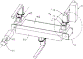
Fig. 2 is a schematic structural diagram of a corner control assembly according to an embodiment of the present application.
Fig. 3 is an exploded view of the corner control assembly in an embodiment of the present application.
Fig. 4 is an enlarged view at a in fig. 3.
Fig. 5 is a schematic structural view of a positioning device according to an embodiment of the present application.
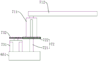
Fig. 6 is a cross-sectional view of a sensing member in an embodiment of the present application.
Reference numerals illustrate:
1. a frame; 2. a discharging mechanism; 21. a reel is unreeled; 22. a guide roller; 3. a traction mechanism; 31. a first traction mechanism; 32. a pressure regulating roller; 33. a second traction mechanism; 4. a die cutting mechanism; 41. die cutting the bracket; 42. an upper template; 43. a lower template; 44. punching heads; 5. a winding mechanism; 51. a mounting frame; 52. a waste material collecting shaft; 53. a waste material winding motor; 54. a main material winding shaft; 55. a main material winding motor; 6. a transmission member; 61. a support table; 62. an endless belt; 63. a driving roller; 64. a drive motor; 65. a connecting piece; 651. a connection station; 6511. a groove; 652. a flexible block; 7. a positioning device; 71. a telescopic pressing member; 711. a cylinder; 712. pressing the blocks; 72. a turntable; 721. a rotating shaft; 722. a mounting table; 73. a driving member; 731. a driving motor; 732. a drive gear; 8. an induction member; 81. a mounting box; 811. a rod hole; 82. a sensor; 83. a supporting rod; 84. a self-restoring member; 841. a return spring; 842. and a fixing piece.
Detailed Description
The present application is described in further detail below in conjunction with figures 1-6.
In the description of the present invention, it should be understood that the terms "center", "longitudinal", "lateral", "length", "width", "thickness", "upper", "lower", "front", "rear", "left", "right", "vertical", "horizontal", "top", "bottom", "inner", "outer", "clockwise", "counterclockwise", etc. indicate orientations or positional relationships based on the orientations or positional relationships shown in the drawings are merely for convenience in describing the present invention and simplifying the description, and do not indicate or imply that the apparatus or elements referred to must have a specific orientation, be configured and operated in a specific orientation, and thus should not be construed as limiting the present invention.
The embodiment of the application discloses a self-adhesive trademark die-cutting machine.
Referring to fig. 1, the self-adhesive trademark die-cutting machine comprises a frame 1, a discharging mechanism 2, a traction mechanism 3, a die-cutting mechanism 4, a winding mechanism 5 and a corner control assembly. The machine frame 1 is placed on the ground, the discharging mechanism 2, the traction mechanism 3, the die cutting mechanism 4, the winding mechanism 5 and the corner control assembly are all arranged on the machine frame 1, and the corner control assembly is positioned on one side of the die cutting mechanism 4.
The trademark raw material roll is placed on the discharging mechanism 2, the discharging mechanism 2 conveys the trademark into the die-cutting mechanism 4, the die-cutting mechanism 4 dies the trademark, the traction mechanism 3 pulls the die-cut trademark to move towards the winding mechanism 5, and meanwhile, the rotation angle control mechanism controls the winding mechanism 5 to rotate at the same time, so that the length of the trademark wound by the winding mechanism 5 is the same as that of the trademark die-cut by the die-cutting mechanism 4.
The discharging mechanism 2 comprises a discharging shaft 21 and a plurality of guide rollers 22, wherein the discharging shaft 21 is fixed at the left end of the frame 1 through a discharging disc, and the discharging shaft 21 is an inflatable shaft in the embodiment. A plurality of guide rollers 22 are fixed on the base frame in turn along the length direction of the frame 1, and the axial direction of the guide rollers 22 is the same as the axial direction of the unreeling shaft 21.
The trademark raw material roll is wound on the unwinding shaft 21, and the trademark raw material is inserted into the die-cutting mechanism 4 after sequentially bypassing the plurality of guide rollers 22.
The die cutting mechanism 4 comprises a die cutting support 41, an upper die plate 42, a lower die plate 43 and a punching head 44, wherein the die cutting support 41 is riveted on the frame 1, the guide roller 22 is positioned between the die cutting support 41 and the unreeling shaft 21, the upper die plate 42 and the lower die plate 43 are both positioned in the die cutting support 41, the lower die plate 43 is fixedly connected with the die cutting support 41, the upper die plate 42 is positioned right above the lower die plate 43, the punching head 44 is arranged on the die cutting support 41, the punching head 44 is positioned above the upper die plate 42, and the bottom end of the punching head 44 is riveted with the upper die plate 42. The lower surface of the upper die plate 42 is fixedly connected with a knife die plate.
The trademark raw material is inserted between the upper template 42 and the lower template 43, the trademark raw material is flatly paved on the lower template 43, the upper template 42 is pushed by the stamping head 44 to move downwards, and when the cutter template is pressed on the trademark raw material, the cutter template completes die cutting of the trademark raw material.
Referring to fig. 1 and 2, the drawing mechanism 3 includes a first drawing mechanism 31, a pressure regulating roller 32 and a second drawing mechanism 33, the first drawing mechanism 31, the pressure regulating roller 32 and the second drawing mechanism 33 are sequentially installed on the frame 1, and the die cutting support 41 is located between the first drawing mechanism 31 and the guide roller 22.
The first traction mechanism 31 pulls the die-cut trademark to move to the pressure regulating roller 32, the pressure regulating roller 32 regulates the tension of the die-cut trademark, the second traction mechanism 33 pulls the main material of the die-cut trademark to move, and the rolling mechanism 5 rolls the waste material and the main material of the die-cut trademark respectively.
The winding mechanism 5 comprises a waste winding mechanism and a main material winding mechanism. The waste material rolling mechanism includes mounting bracket 51, waste material rolling axle 52 and waste material rolling motor 53, and mounting bracket 51 is fixed in frame 1, and mounting bracket 51 is located second traction mechanism 33 right side, and waste material rolling axle 52 and rolling motor are all located on mounting bracket 51, and the rolling motor drives waste material rolling axle 52 rotation. The main material winding mechanism comprises a main material winding shaft 54 and a main material winding motor 55, the main material winding shaft 54 is installed on the frame 1 through a bearing seat, the main material winding motor 55 drives the main material winding shaft 54 to rotate, and the waste material winding shaft 52 is located above the main material winding shaft 54.
The die-cut trademark is separated into waste and main materials after passing through the pressure regulating roller 32, the waste is wound on the waste winding shaft 52, the main materials are wound on the main material winding shaft 54 through the traction of the second traction mechanism 33, and the main material winding motor 55 drives the main material winding shaft 54 to rotate, so that the main materials can be wound on the main material winding shaft 54. Meanwhile, the scrap winding motor 53 drives the scrap winding shaft 52 to rotate, winding the scrap on the scrap winding shaft 52.
Referring to fig. 1 and 2, the rotation angle control assembly includes a transmission member 6, a positioning device 7, and a sensing member 8. The transmission piece 6 and the induction piece 8 are both arranged on the frame 1, and the transmission piece 6 and the induction piece 8 are both positioned on the same side of the die-cutting bracket 41. The positioning devices 7 may have three, four, five, etc., and the positioning devices 7 of this embodiment have three, three positioning devices 7 are all mounted on the transmission member 6, and the lengths of the endless belts 62 between the three positioning devices 7 are equal.
When the sensing piece 8 senses that the moving distance of the positioning device 7 is equal to the length of the die cutting completion of the close mechanism, the sensing piece 8 sends out a signal, and the winding mechanism 5 and the transmission piece 6 stop working to complete winding.
Referring to fig. 2 and 3, the transfer member 6 includes a support table 61, an endless belt 62, a driving roller 63, a driving motor 64, and a connecting member 65, the support table 61 is welded to the frame 1, the endless belt 62 is an endless transfer belt, the endless belt 62 is sleeved on the support table 61, and an inner wall of the endless belt 62 abuts against an upper surface and a lower surface of the support table 61. The driving motor 64 is riveted on the supporting table 61, one end of the driving roller 63 is coaxially connected to a motor shaft of the driving motor 64, and the other end of the driving roller 63 is inserted into the endless belt 62 and abuts against an inner peripheral wall of the endless belt 62.
The connecting members 65 are mounted on the outer peripheral wall of the endless belt 62, the number of the connecting members 65 is the same as the number of the positioning devices 7, the lengths of the endless belt 62 between two adjacent connecting members 65 are equal, and one positioning device 7 is mounted on each connecting member 65.
Referring to fig. 3 and 4, the connection member 65 includes a connection table 651 and a flexible block 652, the connection table 651 and the flexible block 652 are adhered to the outer circumferential wall of the endless belt 62, grooves 6511 are provided on the surface of the connection table 651 facing the endless belt 62, the length direction of the grooves 6511 is the same as the width direction of the endless belt 62, both ends of the length direction of the grooves 6511 penetrate through the side wall of the connection table 651, the flexible block 652 is located in the grooves 6511, and the flexible block 652 is adhered to the groove wall of the grooves 6511.
Referring to fig. 4 and 5, the positioning device 7 includes a telescopic presser 71, a turntable 72, and a rotation driving member 73, both the turntable 72 and the rotation driving member 73 being mounted on a connection table 651, the telescopic presser 71 being mounted on the turntable 72. The turntable 72 includes a rotation shaft 721 and a mounting table 722, the rotation shaft 721 is welded to the connection table 651, and the rotation shaft 721 is disposed in the vertical direction. The mounting table 722 is rotatably coupled to the top end of the shaft 721.
The driving member 73 includes a driving motor 731 and a driving gear 732, the driving motor 731 is riveted to the connection table 651, and a motor shaft of the driving motor 731 is parallel to an axis of the rotation shaft 721. The drive gear 732 is coaxially connected to the motor shaft of the drive motor 731, and the drive gear 732 is engaged with the peripheral wall of the mount 722.
The telescopic pressing piece 71 includes an air cylinder 711 and a pressing block 712, the air cylinder 711 is fixedly connected to the mounting table 722 in the vertical direction, one end of the pressing block 712 is welded to the top end of the air cylinder 711, and the pressing block 712 is disposed in the horizontal direction.
The driving motor 731 is started, the driving gear 732 and the mounting table 722 are rotated, the air cylinder 711 and the pressing block 712 are rotated in synchronization, when the end of the pressing block 712 away from the air cylinder 711 is inserted between the upper die plate 42 and the lower die plate 43, the driving motor 731 is turned off, and then the air cylinder 711 is operated to contract, the pressing block 712 moves downward and abuts the trademark against the lower die plate 43.
Referring to fig. 4 and 6, the sensing member 8 includes a mounting case 81, a sensor 82, a lever 83, and a self-restoring member 84. The mounting box 81 is riveted to the frame 1, and the mounting box 81 is located at the right end of the support table 61. The sensor 82 and the self-recovery member 84 are both located in the installation box 81, the sensor 82 is riveted on the inner box wall on the right side of the installation box 81, a rod hole 811 is formed in the left box wall of the installation box 81, the abutment rod 83 is inserted into the rod hole 811, and the abutment rod 83 is arranged in the horizontal direction. When the pressing block 712 abuts the trademark against the lower die plate 43, the left end of the abutment 83 faces the pressing block 712, and the right end of the abutment 83 faces the sensor 82.
The self-restoring member 84 includes a restoring spring 841 and a fixing plate 842, the fixing plate 842 is welded on the supporting rod 83, the restoring spring 841 may have one, two, three or four, etc., the four restoring springs 841 of this embodiment are all welded with the fixing plate 842, one end of the restoring spring 841 far away from the fixing plate 842 is all welded with the right inner wall of the installation box 81, and the sensor 82 is located between the four restoring springs 841.
When the pressing block 712 moves synchronously with the trademark, the pressing block 712 moves in a direction approaching to the abutment 83, when the pressing block 712 contacts with the abutment 83, the pressing block 712 pushes the abutment 83 to move in a direction approaching to the sensor 82, when the abutment 83 contacts with the sensor 82, the distance moved by the pressing block 712 is equal to the length of the die-cutting mechanism 4 for completing die-cutting, at this time, the sensor 82 sends a signal, the transmission member 6 and the winding mechanism 5 stop working, the pressing block 712 stops moving, and the die-cut trademark is wound.
The implementation principle of the self-adhesive trademark die-cutting machine provided by the embodiment of the application is as follows: firstly, placing a trademark raw material roll on a discharging shaft, then inserting the trademark into a die cutting mechanism 4, then sequentially passing through a first traction mechanism 31 and a pressure regulating roller 32, separating the trademark into waste materials and main materials, winding the waste materials on a waste material winding shaft 52, and winding the main materials on a main material winding shaft 54 after passing through a second winding mechanism 5.
The driving motor 731 is started, the driving gear 732 drives the mounting table 722 to rotate, and the driving motor 731 is turned off when the pressing block 712 is inserted between the upper die plate 42 and the lower die plate 43. Then, the driving motor 64 is started, the driving roller 63 drives the endless belt 62 to move, and when the pressing block 712 moves to the left end of the support table 61, the driving motor 64 is turned off.
The re-operation cylinder 711 is contracted, and the pressing block 712 moves downward and presses the brand raw material against the lower die plate 43. The punch head 44 is then operated to drive the upper die plate 42 downwardly, the knife die plate being pressed against the label stock and completing die cutting of the label stock.
Then, the main material winding motor 55, the waste material winding motor 53 and the driving motor 64 are started, the pressing block 712 moves synchronously with the trademark, and when the pressing block 712 contacts with the supporting rod 83, the supporting rod 83 is pushed to move, and meanwhile, the spring is elastically deformed. When the right end of the abutment 83 contacts with the sensor 82, the sensor 82 sends out a signal, and the main material winding motor 55, the waste material winding motor 53 and the driving motor 64 stop rotating at the same time, so that the die-cut trademark is separated into waste material and main material, and the waste material and the main material are wound on the waste material winding shaft 52 and the main material winding shaft 54 respectively.
The re-operation cylinder 711 is extended, the pressing block 712 moves upward and out of contact with the trademark, and the driving motor 731 is started to rotate reversely, turning the pressing block 712 back directly above the endless belt 62. Then the left adjacent positioning device 7 is operated to press the trademark, and the operation is repeated, so that the trademark die cutting and winding work can be completed.
The foregoing are all preferred embodiments of the present application, and are not intended to limit the scope of the present application in any way, therefore: all equivalent changes in structure, shape and principle of this application should be covered in the protection scope of this application.
Claims (8)
1. The utility model provides a self-adhesive trade mark cross cutting machine, includes frame (1), blowing mechanism (2), traction mechanism (3), cross cutting mechanism (4) and winding mechanism (5), its characterized in that: still include corner control assembly, blowing mechanism (2), traction mechanism (3), cross cutting mechanism (4) and winding mechanism (5) are all located on frame (1), corner control assembly includes transmission piece (6), positioner (7) and induction piece (8), transmission piece (6) and induction piece (8) are all installed on frame (1), transmission piece (6) are located cross cutting mechanism (4) one side, a plurality of positioner (7) are evenly located in proper order on transmission piece (6), induction piece (8) are located transmission piece (6) one end, induction piece (8) are relative with positioner (7).
2. The self-adhesive trademark die-cutting machine of claim 1, wherein: the positioning device (7) comprises a telescopic pressing piece (71), a rotary table (72) and a driving piece (73) for driving the rotary table (72) to rotate, the rotary table (72) and the driving piece (73) are both arranged on the transmission piece (6), the telescopic pressing piece (71) is arranged on the rotary table (72), the driving piece (73) is connected with the rotary table (72), and the sensing piece (8) is opposite to the telescopic pressing piece (71).
3. The self-adhesive trademark die-cutting machine of claim 2, wherein: the telescopic pressing piece (71) comprises an air cylinder (711) and a pressing block (712), the air cylinder (711) is fixedly connected to the rotary table (72), the pressing block (712) is fixedly connected to the telescopic end of the air cylinder (711), and the sensing piece (8) is opposite to the pressing block (712).
4. A self-adhesive brand die-cutting machine as defined in claim 3, wherein: the rotary driving part (73) comprises a driving motor (731) and a driving gear (732), the driving motor (731) is fixedly connected to the transmission part (6), the driving gear (732) is fixedly connected to a motor shaft of the driving motor (731), the rotary table (72) comprises a rotary shaft (721) and a mounting table (722), the rotary shaft (721) is fixedly connected to the transmission part (6), the mounting table (722) is rotatably connected to the rotary shaft (721), the driving gear (732) is meshed with the mounting table (722), and the air cylinder (711) is fixedly connected to the mounting table (722).
5. The self-adhesive trademark die-cutting machine of claim 1, wherein: the transmission piece (6) comprises a supporting table (61), an annular belt (62), a driving roller (63), a driving motor (64) and a connecting piece (65), wherein the supporting table (61) is fixedly connected to the frame (1), the annular belt (62) is sleeved outside the supporting table (61), the driving motor (64) is fixedly connected to the supporting table (61), the driving roller (63) is inserted into the annular belt (62), the driving roller (63) is abutted to the inner peripheral wall of the annular belt (62), the driving roller (63) is coaxially connected with a motor shaft of the driving motor (64), the connecting piece (65) is mounted on the outer peripheral wall of the annular belt (62), and the positioning device (7) is connected with the connecting piece (65).
6. The self-adhesive trademark die-cutting machine of claim 5, wherein: the connecting piece (65) comprises a connecting table (651) and a flexible block (652), wherein the connecting table (651) and the flexible block (652) are fixedly connected to the peripheral wall of the annular belt (62), grooves (6511) are formed in the side wall, facing the annular belt (62), of the connecting table (651), the flexible block (652) is inserted into the grooves (6511), the flexible block (652) is fixedly connected with the groove wall of the grooves (6511), and the positioning device (7) is installed on the connecting table (651).
7. The self-adhesive trademark die-cutting machine of claim 1, wherein: the induction piece (8) comprises an installation box (81), a sensor (82), a supporting rod (83) and a self-restoring piece (84), wherein the installation box (81) is fixedly connected to the frame (1), the sensor (82) and the self-restoring piece (84) are both located in the installation box (81), the sensor (82) is fixedly connected to the inner wall of the installation box (81), a rod hole (811) is formed in the installation box (81), the supporting rod (83) is arranged in the rod hole (811) in a penetrating mode, the supporting rod (83) is arranged between the positioning device (7) and the sensor (82), one end of the self-restoring piece (84) is connected with the supporting rod (83), and the other end of the self-restoring piece (84) is connected with the inner wall of the installation box (81).
8. The self-adhesive trademark die-cutting machine of claim 7, wherein: the self-restoring piece (84) comprises a restoring spring (841) and a fixing piece (842), the fixing piece (842) is fixedly connected to the supporting rod (83), one end of the restoring spring (841) is fixedly connected with the wall of the installation box (81), and the other end of the restoring spring (841) is fixedly connected with the fixing piece (842).
Priority Applications (1)
| Application Number | Priority Date | Filing Date | Title |
|---|---|---|---|
| CN202310094679.4A CN115991402A (en) | 2023-01-30 | 2023-01-30 | Self-adhesive trademark die-cutting machine |
Applications Claiming Priority (1)
| Application Number | Priority Date | Filing Date | Title |
|---|---|---|---|
| CN202310094679.4A CN115991402A (en) | 2023-01-30 | 2023-01-30 | Self-adhesive trademark die-cutting machine |
Publications (1)
| Publication Number | Publication Date |
|---|---|
| CN115991402A true CN115991402A (en) | 2023-04-21 |
Family
ID=85993375
Family Applications (1)
| Application Number | Title | Priority Date | Filing Date |
|---|---|---|---|
| CN202310094679.4A Pending CN115991402A (en) | 2023-01-30 | 2023-01-30 | Self-adhesive trademark die-cutting machine |
Country Status (1)
| Country | Link |
|---|---|
| CN (1) | CN115991402A (en) |
-
2023
- 2023-01-30 CN CN202310094679.4A patent/CN115991402A/en active Pending
Similar Documents
| Publication | Publication Date | Title |
|---|---|---|
| US6325952B1 (en) | Continuous gasket making machine and method | |
| CN214267103U (en) | Quick waste discharge equipment of label | |
| CN110540092B (en) | Intelligent control printing and die cutting integrated machine | |
| CN112249792B (en) | Automatic high-speed adhesive sticker trademark die-cutting machine and die-cutting process | |
| JP2022536954A (en) | Coil material tail punching, pasting, tape feeding, cutting device and method | |
| CN115991402A (en) | Self-adhesive trademark die-cutting machine | |
| CN211437677U (en) | Sheet punching forming device | |
| CN218893173U (en) | Feeding mechanism and feeding device | |
| CN111702067A (en) | Processing equipment and processing method of stamping part | |
| CN114309262A (en) | Aluminum foil forming equipment | |
| CN113276205B (en) | Waste discharge device of die-cutting machine | |
| CN213622728U (en) | Winding mechanism of non-setting adhesive trademark die cutting machine | |
| CN111377273A (en) | Laminating device is cut to coil stock | |
| CN210455504U (en) | Easily tear and paste feed mechanism | |
| CN114040567A (en) | Punching and forming method of FPC product | |
| CN210655466U (en) | Intelligent control printing and die cutting integrated machine | |
| CN112324771A (en) | Accurate automatic laminating equipment of sheetmetal | |
| CN210823193U (en) | Labeling machine | |
| CN216937967U (en) | Aluminum foil forming equipment | |
| CN113184577A (en) | Children's book production line of visiting | |
| JP2594613Y2 (en) | Film sheet feeder | |
| CN113858692B (en) | Cigarette case die cutting machine and using method thereof | |
| CN215366293U (en) | Ironing and embroidering integrated machine | |
| CN219705491U (en) | Full-automatic platen die cutting indentation machine | |
| CN213950041U (en) | Automatic printing machine |
Legal Events
| Date | Code | Title | Description |
|---|---|---|---|
| PB01 | Publication | ||
| PB01 | Publication | ||
| SE01 | Entry into force of request for substantive examination | ||
| SE01 | Entry into force of request for substantive examination |