CN1159829C - Vibration generation system and method for mounting counterbalance on the vibration generation system - Google Patents
Vibration generation system and method for mounting counterbalance on the vibration generation system Download PDFInfo
- Publication number
- CN1159829C CN1159829C CNB99102978XA CN99102978A CN1159829C CN 1159829 C CN1159829 C CN 1159829C CN B99102978X A CNB99102978X A CN B99102978XA CN 99102978 A CN99102978 A CN 99102978A CN 1159829 C CN1159829 C CN 1159829C
- Authority
- CN
- China
- Prior art keywords
- balancing weight
- axle
- mentioned
- recess
- patchhole
- Prior art date
- Legal status (The legal status is an assumption and is not a legal conclusion. Google has not performed a legal analysis and makes no representation as to the accuracy of the status listed.)
- Expired - Lifetime
Links
Images


Classifications
-
- H—ELECTRICITY
- H02—GENERATION; CONVERSION OR DISTRIBUTION OF ELECTRIC POWER
- H02K—DYNAMO-ELECTRIC MACHINES
- H02K7/00—Arrangements for handling mechanical energy structurally associated with dynamo-electric machines, e.g. structural association with mechanical driving motors or auxiliary dynamo-electric machines
- H02K7/06—Means for converting reciprocating motion into rotary motion or vice versa
- H02K7/075—Means for converting reciprocating motion into rotary motion or vice versa using crankshafts or eccentrics
-
- H—ELECTRICITY
- H02—GENERATION; CONVERSION OR DISTRIBUTION OF ELECTRIC POWER
- H02K—DYNAMO-ELECTRIC MACHINES
- H02K7/00—Arrangements for handling mechanical energy structurally associated with dynamo-electric machines, e.g. structural association with mechanical driving motors or auxiliary dynamo-electric machines
- H02K7/06—Means for converting reciprocating motion into rotary motion or vice versa
- H02K7/061—Means for converting reciprocating motion into rotary motion or vice versa using rotary unbalanced masses
-
- B—PERFORMING OPERATIONS; TRANSPORTING
- B06—GENERATING OR TRANSMITTING MECHANICAL VIBRATIONS IN GENERAL
- B06B—METHODS OR APPARATUS FOR GENERATING OR TRANSMITTING MECHANICAL VIBRATIONS OF INFRASONIC, SONIC, OR ULTRASONIC FREQUENCY, e.g. FOR PERFORMING MECHANICAL WORK IN GENERAL
- B06B1/00—Methods or apparatus for generating mechanical vibrations of infrasonic, sonic, or ultrasonic frequency
- B06B1/10—Methods or apparatus for generating mechanical vibrations of infrasonic, sonic, or ultrasonic frequency making use of mechanical energy
- B06B1/16—Methods or apparatus for generating mechanical vibrations of infrasonic, sonic, or ultrasonic frequency making use of mechanical energy operating with systems involving rotary unbalanced masses
-
- Y—GENERAL TAGGING OF NEW TECHNOLOGICAL DEVELOPMENTS; GENERAL TAGGING OF CROSS-SECTIONAL TECHNOLOGIES SPANNING OVER SEVERAL SECTIONS OF THE IPC; TECHNICAL SUBJECTS COVERED BY FORMER USPC CROSS-REFERENCE ART COLLECTIONS [XRACs] AND DIGESTS
- Y10—TECHNICAL SUBJECTS COVERED BY FORMER USPC
- Y10T—TECHNICAL SUBJECTS COVERED BY FORMER US CLASSIFICATION
- Y10T29/00—Metal working
- Y10T29/49—Method of mechanical manufacture
- Y10T29/49002—Electrical device making
- Y10T29/49009—Dynamoelectric machine
- Y10T29/49012—Rotor
Abstract
A weight that is formed semicircular in section and has a recess near both side of a insertion hole of a shaft. The weight, after being inserted onto the shaft, is supported in an inclined position by a support member. A pressing member is dropped from the upper of weight to apply a pressure to the recess. In this way, the pressure is offset from the rotational axis of the shaft.
Description
Technical field
The present invention relates in a kind of controller that is contained in electronic game machine etc., be used for making controller self to vibrate, perhaps be used for reporting the vibration generating arrangement of mobile phone or radio pager received signal and the balancing weight installation method on the above-mentioned vibration generating arrangement.
Background technology
Fig. 8 is the method for balancing weight is installed in explanation on the axle of the motor of existing vibration generating arrangement a front view, expression be state before installing.Fig. 9 is the front view that the back state is installed in expression.
Above-mentioned existing balancing weight 10 is the radially central portion of semicircular columnar body 11 in its cross section, is formed with the U-lag 4 of axle 3 usefulness of inserting motor, forms projection 13a, 13b upwards in the both sides of above-mentioned U-lag 4.
When above-mentioned balancing weight 10 is installed on axle 3, at first axle 3 is inserted and remains in the U-lag 4 of balancing weight 10.Support balancing weight 10 with a bearing 1, this bearing 1 has the identical shape of circumferential part (curve part) with balancing weight 10, the chimeric balancing weight 10 that supports of the curve part 1a by this bearing 1 and the circumferential part of balancing weight 10.In this case, the par of balancing weight 10 keeps level.
Then, make that to have the cross section be that the pressure-producing part 12 of leg-of-mutton recess 12a falls from the top of the balancing weight 10 that supporting,, balancing weight 10 is installed on the axle 3 its pressurization.In other words, littler at the area of the recess 12a that the leading section of pressure-producing part 12 forms than the area of the space formation between above-mentioned projection 13a, 13b and two projection 13a, the 13b.Therefore, depress to the front end of projection 13a, 13b at recess 12a with pressure-producing part 12, and again when pressing down, two just direction (arrow R, L) bendings to the inside of projection 13a, 13b, balancing weight 10 just has been installed on the axle 3.
But, though Fig. 8 and existing balancing weight 10 shown in Figure 9 and installation method thereof are applicable to the balancing weight made from softer material such as copper 10, but make, just needed very big pressure at 3 o'clock balancing weight 10 being loaded onto axle as harder materials such as balancing weight 10 usefulness iron.
In addition, if the pressure that balancing weight 10 is contained in when spool last is little, then only need a very little power just the balancing weight of installing with existing method 10 can be pulled up from axle 3, therefore, when the motor of above-mentioned balancing weight 10 was equipped with in the reality use, it is loosening with axle 3 that balancing weight 10 (during use) in rotation can take place, and produces abnormal sound, even may break away from axle 3, thereby damage device itself.
In other words, Fig. 8 and the balancing weight with U-lag 4 10 shown in Figure 9, when pressurizeing by pressure-producing part 12, because the interior sidewall surface of U-lag 4 forms linearity, so must make the interior sidewall surface of this linearity produce very big distortion, become along the curved surface of axle 3, therefore when projection 13a, 13b are pressurizeed, must use very big pressure.So, when projection 13a, 13b are pressurizeed pressure little deformation just insufficient, the interior sidewall surface of U-lag 4 is just little with the contact area of axle 3 curved surface.Consequently, install insecurely, as large-scale balancing weight is installed, the gravity of balancing weight is very big, and then balancing weight 10 just might come off from axle 3.
Summary of the invention
The present invention develops and finishes in order to solve above-mentioned problem, provide a kind of under the situation of using relatively hard materials such as iron even its objective is, pressure required when pressurizeing with pressure-producing part is also less, and the vibration generating arrangement of the danger that balancing weight comes off in not having to use and the balancing weight installation method on the above-mentioned vibration generating arrangement.
Vibration generating arrangement of the present invention is a kind of vibration generating arrangement that the balancing weight that produces vibration usefulness is installed on the axle of motor.Wherein, above-mentioned balancing weight cross section is semicircular in shape roughly, and this balancing weight is formed by the multi-layered sheet lamination, its radially the part of central portion form open shaft insertion hole, and near the position above-mentioned patchhole open portion forms the fixedly recess of usefulness, the interval of above-mentioned shaft insertion hole open portion is littler than the diameter of above-mentioned axle, and above-mentioned axle is under the state that inserts above-mentioned patchhole, by more being fixed in the patchhole by the side pressurization of open end to above-mentioned recess or than above-mentioned recess.
By above-mentioned way,, also can balancing weight be fixedly mounted on the axle with the pressure littler than the past even harder materials such as balancing weight employing iron are made.In addition, because can make, so cost is expected to reduce with the lower-cost material of iron and so on.And the easy fine finishining of iron, not yielding, so difficult drop-off.
In these cases, the angle of the internal face of the above-mentioned patchhole of coating axle is more preferably greater than 180 degree.
Like this, under the situation that makes its distortion that balancing weight is pressurizeed, can contact axle maintenance face.That is to say, because the internal face of patchhole is same curved surface with axle basically, so when the internal face of patchhole was out of shape because of pressurization, above-mentioned internal face contacted with the curved surface formation face of axle.Balancing weight just can be installed on the axle more firmly than existing U-lag mode like this.
The internal face of above-mentioned patchhole is preferably more than the 1/100mm with the gap of axle, below the 8/100mm.As more than 3/100mm, 5/100mm is with next better.
Like this, balancing weight when pressurization can be positively, be securely fixed on the axle.Above-mentioned gap is as less than 1/100mm, and then machining accuracy is difficult to reach requirement, and the insertion of axle also has any problem, and the gap is as greater than 8/100mm, and the internal face of patchhole is too little with the contact area of axle when then pressurizeing, and balancing weight just can not be fixedly mounted on the axle.
In addition, the thickness between the internal face of above-mentioned recess and patchhole is more preferably greater than 0.5 times of shaft diameter, less than 1 times.
Thickness setting is in above-mentioned scope, and balancing weight just can be securely fixed on the axle.Above-mentioned thickness is as surpassing 1 times of shaft diameter, and when balancing weight pressurize, the distortion of the internal face of shaft insertion hole was difficult, and balancing weight can't be fixed on the axle, and during less than 0.5 times, then balancing weight remain on the axle power too a little less than, so also bad.
Balancing weight installation method on the vibration generating arrangement involved in the present invention is by wearing the operation that hangs on the axle with the balancing weight of motor, the operation that balancing weight is maintained fixed, and the operation that pressurization is fixed on the axle to balancing weight is formed.Wherein, with cross section semicircular in shape roughly, and its radially the part of central portion form interval open, this open portion than the diameter of above-mentioned axle little insert the shaft insertion hole of usefulness for axle, and near the position the above-mentioned open portion of above-mentioned patchhole be provided with recess pass through balancing weight that the laminated multilayer thin plate forms wear hang on the axle after, make the flat surfaces of above-mentioned balancing weight keep tilting, more pressurize to above-mentioned recess or than above-mentioned recess with pressure-producing part by a side of open end, inwardly pressurize in axle center facing to axle, balancing weight and axle are firmly fixed together.
In said method, above-mentioned balancing weight is worn the axle that hangs over motor and is gone up on the bearing that is placed on special use afterwards.At this moment the laying method of balancing weight in bearing is to make the flat of balancing weight keep tilting.Balancing weight put appropriate after, from the pressurization of the top of balancing weight, the recess that forms on the balancing weight or more join by a side and the pressure-producing part of open end than recess at this moment is by further exerting pressure to balancing weight downwards with pressure-producing part, the internal face distortion of shaft insertion hole is fixed on balancing weight on the axle.
In these cases, with pressure-producing part to the position of balancing weight pressurization preferably than recess more by a side of open end.Balancing weight can be fixedly mounted on the axle like this.
In addition, in this case, the axis direction of the best off-axis of center position of pressurization.With the compression aspect off-axis,, can not cause the damage of axle as above-mentioned just when pressure-producing part impacts, can directly not exert pressure to axle.
In addition, pressures partially at this moment can be the recess that forms in the patchhole both sides, also can be a side of more leaning on the open end than recess.
Description of drawings
With reference to the accompanying drawings the balancing weight installation method on vibration generating arrangement of the present invention and the vibration generating arrangement is described.
Fig. 1 is the front view of expression balancing weight shape of the present invention.
Fig. 2 is the front view of another embodiment of expression balancing weight of the present invention.
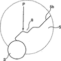
Fig. 3 is the explanation key diagram that the method for balancing weight is installed on axle of the present invention.
Fig. 4 is the part enlarged front view of the state before expression is installed.
Fig. 5 is the part enlarged front view of the state after expression is installed.
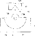
Fig. 6 is the front view that the expression balancing weight is contained in the state on the motor.
Fig. 7 A, Fig. 7 B, Fig. 7 C are the key diagrams that the explanation balancing weight is contained in the process on the axle.
Fig. 8 is the shape of the existing balancing weight of expression and is contained in a key diagram of the state of going forward.
Fig. 9 installs the key diagram of state afterwards.
Embodiment
Fig. 1 and Fig. 2 are respectively the enlarged front views of the balancing weight shape that varies in size of expression.
Balancing weight 5 shown in Fig. 1 is that semicircular columnar body 5a constitutes by the cross section, the central portion of the par of main body 5a 5b set in the outstanding protuberance 5e of foreign side, inwardly be formed with the patchhole 6 that inserts usefulness for axle 3, and the part of opening of above-mentioned patchhole 6, peristome 7 become.Above-mentioned patchhole 6 is positioned at the center of the circumferential part of balancing weight 5, give prominence to foreign side on 5b surface, par, therefore the distance with the center of gravity of balancing weight 5 is longer, when balancing weight 5 rotates with axle 3, balancing weight is subjected to maximum action of centrifugal force, can produce bigger vibration as vibration generating arrangement.
Recess 8 under a side of above-mentioned patchhole 6 is formed with way from peristome 7 to par 5b, concaving.Be formed with recess equally at the opposite side of patchhole 6 also left and right symmetrically.
In the present invention, the axle 3 and patchhole 6 gaps of motor 9 are preferably more than the 1/100mm, below the 8/100mm, above-mentioned gap is as less than 1/100mm, then machining accuracy is difficult to reach requirement, and axle 3 insertion also has any problem, and the gap is as greater than 8/100mm, the internal face of patchhole 6 was too little with the contact area of axle 3 when then recess 8 pressurizeed, and balancing weight 5 just can not be fixedly mounted on the axle 3.
In addition, the thickness between the internal face of recess 8 and patchhole 6 is more preferably greater than 0.5 times of shaft diameter, less than 1 times.Thickness setting is in above-mentioned scope, and balancing weight 5 just can be securely fixed on the axle 3.
Balancing weight 5 shown in Figure 1 is that gap between φ 1, recess 8 and the patchhole 6 is L1 as the aperture with patchhole, and the angle that coats the patchhole of axle 3 is α 1, and then its value is respectively 2.01mm, and 1.1mm spends with 263.The L1 of above-mentioned this balancing weight 5 is about 0.5 times of φ 1.
Balancing weight 15 shown in Figure 2, just little than balancing weight shown in Figure 15, be the same with the structure of balancing weight 5, as the aperture with its patchhole 6 is that gap between φ 2, recess 8 and the patchhole 6 is L2, the angle that coats axle 3 is α 2, and then its value is respectively 1.52mm, 0.8mm and 276 degree.Like this, the L2 of balancing weight 15 is about 0.5 times of φ 2.
Harder materials such as above-mentioned balancing weight 5,15 usefulness iron are made, and specifically common zinc-plated cold-rolled steel sheet (SECC) etc. are more suitable, and the easy fine finishining of this class material is not yielding, and the back that can prevent to pressurize takes place loosening, comes off from axle 3.
Above-mentioned balancing weight 5 forms column along the length direction of axle 3, and as shown in Figure 6, is formed by some pieces of thin plate 5d laminations.
On each thin plate 5d of the main body 5a that constitutes balancing weight 5, form circular protrusions 5c, 5c shown in Figure 1.
Balancing weight 15 is also the same with method recited above, is formed by the thin plate lamination, in the length direction formation column of axle 3.
Below with reference to Fig. 3 to Fig. 5 the balancing weight installation method on the vibration generating arrangement of the present invention is described.
First procedure is that above-mentioned balancing weight 5 is worn on the axle 3 of hanging and remain on motor 9 by the patchhole 6 of balancing weight 5.In this case, above-mentioned patchhole 6 coats axle 3 with the angle greater than 180 degree, and axle 3 can not come off by peristome 7 like this.
Second operation work is that the balancing weight 5 that will be contained on the motor 9 is bearing on the special-purpose bearing 1.A recess is formed at the top of the rectangle pedestal of this bearing 1, and this recess has the same curved surface of circumferential part (curve part) with balancing weight 5, and some incision-like 1a linearly.Like this, as shown in Figure 3, balancing weight 5 is positioned in the recess of this bearing 1 after, the S point of bearing 1 is dropped in the end of balancing weight 5, is keeping heeling condition.
Three process is under balancing weight 5 is bearing in state in the recess of bearing 1 as mentioned above, and pressure-producing part 2 is fallen from the top of balancing weight 5, to its pressurization, balancing weight 5 is fixed on the axle 3.At this moment used pressure-producing part 2 adopts the tapered parts of forward end, and the front end of pressure-producing part 2 forms R, and its thickness degree is as the criterion with the recess 8 that can embed balancing weight 5.Front end as pressure-producing part 2 is too thick, and power can not focus on a bit when then pressurizeing, and disperses, and balancing weight 5 just can not be securely fixed on the axle 3.Pressure-producing part 2 should the open end by a side direction of axle 3 from the recess 8 that balancing weight 5 forms and vertically fall (direction of arrow the figure), pressurizes.
Fig. 4 is illustrated under the state that balancing weight 5 is supported on bearing 1, the part enlarged front view of axle 3 and the shape of recess 8.
As shown in Figure 4, above balancing weight 5, when recess 8 pressurizeed by open end one side of axle 3, the compression aspect of pressure-producing part 2 was the direction shown in the arrow P among the figure.That is to say that the pressure shown in the direction of arrow P is the axis direction of off-axis 3.
Fig. 5 is the part enlarged front view of the shape of the recess 8 after the expression pressurization.
With method shown in Figure 4 balancing weight 5 is pressurizeed, recess 8 goes down by depressing further depression pressure-producing part 2, the wall of protuberance 5e between the internal face of recess 8 and patchhole 6 is under axle 3 one side pressures, and its result makes near the internal face of the patchhole 6 peristome 7 lean on to axle 3, pushes down axle 3.In this case, because the internal face of patchhole 6 has just formed the curved surface same with axle 3 in advance, so the internal face of patchhole 6 has two places face in a big way contact with face along the curved surface of axle 3 with axle 3, make spools 3 and balancing weight 5 firmly, positively be fixed together.Peristome 7 plays a part to make the internal face of patchhole 6 successfully to rely on the space of axle 3 one sides.
Refer again to Fig. 7 A, Fig. 7 B below, Fig. 7 C is elaborated.Fig. 7 A, Fig. 7 B, Fig. 7 C are the key diagrams that explanation balancing weight 5 is fixed in axle 3 process, Fig. 7 A represent to pressurize state of beginning, the state during Fig. 7 B represents to pressurize, Fig. 7 C state after finishing of representing to pressurize.
Under state shown in Fig. 7 A, pressure-producing part 2 vertical lower and with the state of the axis deviation of axle 3 under, to the open end one side pressurization of recess 8.In this case, pressure-producing part 2 falls from the top of open end one side of recess 8, joins further pressurization with the face of open end one side of recess 8.At this moment, the pressure F of pressure-producing part 2 is to direction (direction of arrow) effect of axle 3.
Under state shown in Fig. 7 B, because of pressure-producing part 2 applied pressures, stress f1 and f2 to axle 3 in balancing weight 5 work, and the elastic force that has because of balancing weight self of balancing weight 5 has produced the stress f3 that pressure-producing part 2 is rolled back in addition.When pressure-producing part 2 further pressurizeed, balancing weight 5 had just produced to the crooked σ 1 of protuberance 5e direction (direction of arrow) that coats axle 3.
Under state shown in Fig. 7 C, pressure-producing part 2 breaks away from balancing weights 5, and at this moment, because of the elasticity of balancing weight 5 self, above-mentioned stress f3 is released, and meanwhile above-mentioned crooked σ 1 is back into crooked σ 2 (rebounding) because of the elasticity cause to the direction of arrow.Like this, axle 3 is positively compressed with patchhole 6, is keeping certain installation strength.
After guaranteeing suitable caulking amount, pressure increases, and pressure-producing part 2 just increases gradually with the contact area of balancing weight 5.Like this, just can control caulking intensity, again because this control does not need to carry out accurate pressure to be set, so can adopt air pressure control such as pneumatic cylinder with the pressure of pressure-producing part 2.
The vibration generating arrangement made from said method can be assembled in the controller of TV or PC recreation usefulness, according to the scene of recreation, the axle 3 of motor 9 is rotated, and rotate balancing weight by runout, produces vibration, thereby can make recreation have more the sense of reality.
As mentioned above, the shape of vibration generating arrangement of the present invention etc. is not limited to the above embodiments, and the patchhole angle that coats axle can be done suitable change according to the size of balancing weight and the thickness of axle etc.
In addition, in balancing weight installation method of the present invention, can adjust the angle of the balancing weight of supporting by the shape of recess.
Claims (5)
1. vibration generating arrangement, it is characterized in that, it is the vibration generating arrangement that the balancing weight that produces vibration usefulness is installed on the axle of motor, wherein, above-mentioned balancing weight cross section is semicircular in shape roughly, and this balancing weight is formed by the multi-layered sheet lamination, its radially the part of central portion form open shaft insertion hole, and near the position above-mentioned patchhole open portion forms the fixedly recess of usefulness, the interval of above-mentioned shaft insertion hole open portion is littler than the diameter of above-mentioned axle, above-mentioned axle is under the state that inserts above-mentioned patchhole, by more being fixed in the patchhole by the side pressurization of open end to above-mentioned recess or than above-mentioned recess.
2. vibration generating arrangement according to claim 1 is characterized in that, the internal face of above-mentioned patchhole is more than the 1/100mm, below the 8/100mm with the gap of axle.
3. vibration generating arrangement according to claim 1 is characterized in that, the thickness between the internal face of above-mentioned recess and patchhole is greater than 0.5 times of shaft diameter, less than 1 times.
4. the balancing weight installation method on the vibration generating arrangement, it is by the balancing weight of motor being worn the operation that hangs on the axle, the operation that balancing weight is maintained fixed, and the operation that pressurization is fixed on the axle to balancing weight is formed, it is characterized in that, with cross section semicircular in shape column roughly, and its radially the part of central portion form open, the shaft insertion hole that the interval of this open portion is littler than the diameter of above-mentioned axle for axle insertion usefulness, and near the position the above-mentioned open portion of above-mentioned patchhole be provided with recess pass through balancing weight that the laminated multilayer thin plate forms wear hang on the axle after, make the face of the radial direction of above-mentioned balancing weight keep tilting, more pressurize to above-mentioned recess or than above-mentioned recess with pressure-producing part by a side of open end, inwardly pressurize in axle center facing to axle, balancing weight and axle are firmly fixed together.
5. the balancing weight installation method on the vibration generating arrangement according to claim 4 is characterized in that, the axis direction of the center position off-axis of pressurization.
Applications Claiming Priority (4)
| Application Number | Priority Date | Filing Date | Title |
|---|---|---|---|
| JP068441/1998 | 1998-03-18 | ||
| JP6844198 | 1998-03-18 | ||
| JP352622/1998 | 1998-12-11 | ||
| JP35262298A JP3708731B2 (en) | 1998-03-18 | 1998-12-11 | Vibration generator and method of attaching a weight to the vibration generator |
Publications (2)
| Publication Number | Publication Date |
|---|---|
| CN1229298A CN1229298A (en) | 1999-09-22 |
| CN1159829C true CN1159829C (en) | 2004-07-28 |
Family
ID=26409665
Family Applications (1)
| Application Number | Title | Priority Date | Filing Date |
|---|---|---|---|
| CNB99102978XA Expired - Lifetime CN1159829C (en) | 1998-03-18 | 1999-03-12 | Vibration generation system and method for mounting counterbalance on the vibration generation system |
Country Status (6)
| Country | Link |
|---|---|
| US (1) | US6288459B1 (en) |
| EP (1) | EP0944156A3 (en) |
| JP (1) | JP3708731B2 (en) |
| KR (1) | KR100320253B1 (en) |
| CN (1) | CN1159829C (en) |
| TW (1) | TW425752B (en) |
Families Citing this family (7)
| Publication number | Priority date | Publication date | Assignee | Title |
|---|---|---|---|---|
| US6600246B2 (en) * | 1998-03-18 | 2003-07-29 | Alps Electric Co., Ltd. | Vibration generating device having a weight caulked to a shaft |
| JP3614093B2 (en) * | 2000-01-28 | 2005-01-26 | 三菱マテリアルシ−エムアイ株式会社 | Small radio vibration generator |
| JP2002079179A (en) * | 2000-09-11 | 2002-03-19 | Mabuchi Motor Co Ltd | Small-sized motor for vibration generation |
| JP2002273344A (en) * | 2001-03-22 | 2002-09-24 | Yasunobu Hiratsuka | Eccentric weight for microvibration motor and its installation method |
| JP2003071382A (en) * | 2001-09-05 | 2003-03-11 | Shicoh Eng Co Ltd | Weight and vibration motor equipped with the same |
| KR100765221B1 (en) * | 2006-03-24 | 2007-10-09 | 강윤규 | A vibrator |
| CN101800452A (en) * | 2010-04-21 | 2010-08-11 | 卧龙电气集团股份有限公司 | Eccentric block vibration mechanism of vibration motor |
Family Cites Families (11)
| Publication number | Priority date | Publication date | Assignee | Title |
|---|---|---|---|---|
| US3344293A (en) * | 1965-07-12 | 1967-09-26 | Eugene A Wahl | Electro-mechanical gyrator |
| US4580456A (en) * | 1983-04-14 | 1986-04-08 | Kikumithus Takano | Balance weight transfer device for a vibrator |
| JPH0614481A (en) * | 1992-06-25 | 1994-01-21 | Mitsubishi Electric Corp | Iron core of armature |
| JPH0698496A (en) * | 1992-09-10 | 1994-04-08 | Matsushita Electric Ind Co Ltd | Vibration-generating motor |
| JPH07107699A (en) * | 1993-09-29 | 1995-04-21 | Matsushita Electric Ind Co Ltd | Vibration generating motor |
| JP3017387B2 (en) * | 1993-12-22 | 2000-03-06 | 三菱マテリアル株式会社 | Vibration generator for small wireless pager |
| JP3536061B2 (en) * | 1994-04-13 | 2004-06-07 | 株式会社メルコテクノレックス | Rotating vibrator and its mounting method |
| JP2865564B2 (en) * | 1994-06-03 | 1999-03-08 | 平和産業株式会社 | Vibration generator |
| JPH08111960A (en) * | 1994-10-10 | 1996-04-30 | Mabuchi Motor Co Ltd | Small-sized motor for generating vibration and manufacture of its vibrator |
| JP3471952B2 (en) * | 1995-01-24 | 2003-12-02 | 東京パーツ工業株式会社 | Eccentric weight of small vibration motor and weight mounting method of the motor |
| JP3158072B2 (en) * | 1997-05-09 | 2001-04-23 | 日本電産コパル株式会社 | Vibrator fixing method and vibration generating motor |
-
1998
- 1998-12-11 JP JP35262298A patent/JP3708731B2/en not_active Expired - Lifetime
-
1999
- 1999-03-01 TW TW088103088A patent/TW425752B/en not_active IP Right Cessation
- 1999-03-03 EP EP99301587A patent/EP0944156A3/en not_active Withdrawn
- 1999-03-12 CN CNB99102978XA patent/CN1159829C/en not_active Expired - Lifetime
- 1999-03-15 KR KR1019990008608A patent/KR100320253B1/en not_active IP Right Cessation
- 1999-03-18 US US09/271,788 patent/US6288459B1/en not_active Expired - Lifetime
Also Published As
| Publication number | Publication date |
|---|---|
| CN1229298A (en) | 1999-09-22 |
| EP0944156A2 (en) | 1999-09-22 |
| TW425752B (en) | 2001-03-11 |
| JPH11319711A (en) | 1999-11-24 |
| KR100320253B1 (en) | 2002-01-10 |
| JP3708731B2 (en) | 2005-10-19 |
| KR19990077884A (en) | 1999-10-25 |
| EP0944156A3 (en) | 2001-02-07 |
| US6288459B1 (en) | 2001-09-11 |
Similar Documents
| Publication | Publication Date | Title |
|---|---|---|
| CN1159829C (en) | Vibration generation system and method for mounting counterbalance on the vibration generation system | |
| CN1415056A (en) | Damped disc brake rotor | |
| CN1082933C (en) | Elevator car hitch | |
| CN1190604C (en) | Screw holder with hook | |
| WO2018134992A1 (en) | Wedge loosening inspection device for dynamo-electric machine | |
| EP0762802B1 (en) | Multi-point drive type speaker | |
| CN1666034A (en) | Tortional damper pulley | |
| CN106286305B (en) | Hard pipeline vibration absorber and compressor | |
| CN1198647A (en) | Loudspeaker installing structure | |
| CN1484882A (en) | Magnet holding structure of rotor | |
| US6688775B2 (en) | Support disk for a support disk bearing for spin rotors | |
| CN1054926C (en) | Timepiece including fixation device for an element added to a frame and method of assembling element on said frame | |
| CN1219983C (en) | Installation structure of bearing seal | |
| CN1146253A (en) | Piano tuning system | |
| CN1505437A (en) | Mounting structure for loudspeaker units | |
| KR20000053043A (en) | Preloading system for a clamp of a stator end winding coil | |
| CN1457397A (en) | Method fo manufacturing valve plate for compressor | |
| CN1738956A (en) | System enabling an assembly of at least one glass sheet and an other object, glass sheet provided with one such system and use of one such sheet | |
| CN1372025A (en) | Support disc base unit for supporting end open spinning rotor | |
| CN214154261U (en) | Novel shaft and fan structure | |
| CN109877230B (en) | Stamping force application structure | |
| CN1088935C (en) | Bearing apparatus of ac. generator for vehicles | |
| CN1063526C (en) | Swash plate type compressor | |
| CN219738469U (en) | Wall-embedded marker light | |
| US6600246B2 (en) | Vibration generating device having a weight caulked to a shaft |
Legal Events
| Date | Code | Title | Description |
|---|---|---|---|
| C10 | Entry into substantive examination | ||
| SE01 | Entry into force of request for substantive examination | ||
| C06 | Publication | ||
| PB01 | Publication | ||
| C14 | Grant of patent or utility model | ||
| GR01 | Patent grant | ||
| CP01 | Change in the name or title of a patent holder |
Address after: Tokyo, Japan Patentee after: Alpine Alpine Company Address before: Tokyo, Japan Patentee before: Alps Electric Co., Ltd. |
|
| CP01 | Change in the name or title of a patent holder | ||
| CX01 | Expiry of patent term |
Granted publication date: 20040728 |
|
| CX01 | Expiry of patent term |