CN115977102A - Upper foundation pit-lower tunnel combined construction structure and construction method in saturated soft loess stratum - Google Patents
Upper foundation pit-lower tunnel combined construction structure and construction method in saturated soft loess stratum Download PDFInfo
- Publication number
- CN115977102A CN115977102A CN202211138387.8A CN202211138387A CN115977102A CN 115977102 A CN115977102 A CN 115977102A CN 202211138387 A CN202211138387 A CN 202211138387A CN 115977102 A CN115977102 A CN 115977102A
- Authority
- CN
- China
- Prior art keywords
- tunnel
- pit
- well
- pipe
- foundation pit
- Prior art date
- Legal status (The legal status is an assumption and is not a legal conclusion. Google has not performed a legal analysis and makes no representation as to the accuracy of the status listed.)
- Pending
Links
Images


Classifications
-
- Y—GENERAL TAGGING OF NEW TECHNOLOGICAL DEVELOPMENTS; GENERAL TAGGING OF CROSS-SECTIONAL TECHNOLOGIES SPANNING OVER SEVERAL SECTIONS OF THE IPC; TECHNICAL SUBJECTS COVERED BY FORMER USPC CROSS-REFERENCE ART COLLECTIONS [XRACs] AND DIGESTS
- Y02—TECHNOLOGIES OR APPLICATIONS FOR MITIGATION OR ADAPTATION AGAINST CLIMATE CHANGE
- Y02E—REDUCTION OF GREENHOUSE GAS [GHG] EMISSIONS, RELATED TO ENERGY GENERATION, TRANSMISSION OR DISTRIBUTION
- Y02E10/00—Energy generation through renewable energy sources
- Y02E10/20—Hydro energy
Landscapes
- Earth Drilling (AREA)
Abstract
An upper foundation pit-lower tunnel combined construction structure and a construction method in a saturated soft loess stratum are disclosed, the structure comprises a foundation pit, the bottom of the foundation pit is communicated with a tunnel through a vertical shaft, and a geogrid is arranged above the bottom of the foundation pit; the outer side of the foundation pit is provided with a steel sheet pile, an in-pit dewatering well, a cast-in-place pile, a jet grouting pile waterproof curtain and an out-pit dewatering well from inside to outside; firstly, constructing a site cast-in-place pile and a jet grouting pile, intercepting underground water outside a foundation pit, driving an out-pit dewatering well at the periphery of a waterproof curtain for dewatering outside the pit, excavating the foundation pit in a grading manner after the out-pit dewatering is finished, driving a steel sheet pile for supporting after the I-section excavation is finished, and driving the steel sheet pile into the dewatering well for dewatering inside the foundation pit; excavating the section II to a preset depth, reinforcing the geogrid at the bottom of the foundation pit, excavating a vertical shaft in the foundation pit to the same depth of a tunnel below, excavating a transverse channel to the tunnel body of the tunnel to the inside of the tunnel, and excavating and supporting; the deformation of the section of the tunnel is effectively controlled, the influence on the foundation pit is reduced, the construction safety is further guaranteed, and the mutual influence between the foundation pit and the tunnel is reduced.
Description
Technical Field
The invention belongs to the technical field of tunnel construction, and particularly relates to an upper foundation pit-lower tunnel combined construction structure and a construction method in a saturated soft loess stratum.
Background
When the saturated soft loess is in precipitation construction, besides the effect of water pressure in water and soil pressure on a supporting structure, the most important points are that foundation pit water gushing and sand gushing and seepage damage (quicksand, abrupt gushing and piping) water and soil loss cause foundation pit instability, ground collapse and drainage consolidation to generate larger compression deformation, the ground surface and surrounding buildings are easy to generate larger additional settlement, and the occurrence rate is faster. Meanwhile, the tunnel excavation is carried out at the bottom of the foundation pit, so that the surrounding ground subsidence and surrounding rock instability can be further caused, and the upper part foundation pit and the tunnel supporting structure are damaged. In the construction process, the control of the difference of the water heads inside and outside the foundation pit is improper, so that the water burst, collapse, foundation uplift and the like of the foundation pit are easily caused.
Currently, the main control measures are: through selecting reasonable groundwater control to prevent the adverse effect of groundwater to the influence of foundation ditch safety and all ring edge borders, guarantee that foundation ditch and underground works are under construction and normally go on, strengthen the tunnel supporting construction that excavates to the lower part simultaneously, reduce the influence to foundation ditch and peripheral earth's surface simultaneously in order to guarantee the safety in the work progress. Under the condition of an upper foundation pit and a lower tunnel, the deformation requirements of the tunnel and the foundation pit are higher, so that the tunnel excavation support should be constructed by a method with less influence on the upper foundation pit, and the advance support is carried out on the tunnel support structure excavated at the lower part, so that the safety in the construction process is ensured, and the influence on the foundation pit and the peripheral earth surface is reduced.
The common precipitation methods at present are: (1) and adding a water collecting well in the open ditch. When the water level is high, the water level is commonly used as an auxiliary drainage measure of a barrier method or other drainage methods, and mainly drains diving, construction water and rainwater; (2) the light well points can be arranged in a single row, double rows, ring shape and other forms on the plane; (3) the well point is sprayed, and the water level lowering depth is large; (4) the electroosmosis well point can effectively suck and discharge water in fine particle soil, needs to be combined with light or spraying for classical application, but is complex in work; (5) the pipe well point is suitable for a gravel layer with a large permeability coefficient and rich underground water; (6) the deep well point has large displacement, large dewatering depth and range, can be arranged at the periphery of the foundation pit, can be arranged in the foundation pit, and can also be combined with other well point systems for application; (7) the comprehensive well points are used when the single well point precipitation cannot achieve satisfactory effects under certain hydrogeological conditions or projects with special requirements. Meanwhile, before precipitation, waterproof curtain construction can be carried out, the permeation of underground water is blocked, and precipitation of a precipitation well is combined to guarantee the effectiveness of precipitation. In the prior art, foundation pit construction or tunnel construction is considered independently, and foundation pit-tunnel linkage cannot be formed. The construction method has defects in the aspects of construction cost control, construction safety guarantee, construction organization implementation and the like.
Disclosure of Invention
In order to overcome the defects of the prior art, the invention aims to provide an upper foundation pit-lower tunnel combined construction structure and a construction method in a saturated soft loess stratum, which can ensure that in the saturated soft loess stratum, a foundation pit exists above the saturated soft loess stratum, and under the condition of tunnel excavation below the saturated soft loess stratum, the ground surface settlement and the difference between the internal water head and the external water head at the bottom of the foundation pit can be controlled, the influence on peripheral buildings is reduced, the deformation and the internal force of a tunnel supporting structure are reduced, the mutual influence between the foundation pit and the tunnel in the construction process is reduced, the deformation and the internal force of the foundation pit and the tunnel are reduced as much as possible, the supporting structure is prevented from being damaged, and the safety and the reliability of the foundation pit and the tunnel supporting structure are improved.
In order to solve the technical problems, the technical scheme adopted by the invention is as follows:
an upper foundation pit-lower tunnel combined construction structure in a saturated soft loess stratum comprises a foundation pit 17, wherein the bottom of the foundation pit 17 is communicated with a tunnel 11 through a vertical shaft 7, and a geogrid 6 is arranged above the bottom of the foundation pit 17; and the outer side of the foundation pit 17 is provided with a steel sheet pile 3, an in-pit dewatering well 5, a cast-in-place pile 2, a jet grouting pile waterproof curtain 1 and an out-pit dewatering well 4 from inside to outside.
The inner side of the foundation pit 17 is provided with a slope structure, the slope structure is arranged into a first slope and a second slope according to the depth, and a slope placing platform is arranged between the first slope and the second slope; the steel sheet piles 3 and the in-pit dewatering well 5 are arranged on a slope releasing platform between the slope surfaces of the second section and the first section; the cast-in-place pile 2, the jet grouting pile waterproof curtain 1 and the pit external precipitation well 4 are arranged at the beginning of the slope surface of the I section.
A combined construction method of an upper foundation pit and a lower tunnel in a saturated soft loess stratum comprises the following steps:
step one, carrying out construction preparation work
1.1, carrying out site investigation and leveling and selecting proper construction machines;
1.2, carrying out technical pile testing before construction, wherein the number of the tested piles is not less than three, and each group comprises four piles;
step two, performing cast-in-place pile construction;
2.1, pile position measurement and lofting are carried out according to the pile position plane layout;
2.2, manufacturing a protective cylinder, and arranging stiffening ribs at the upper and lower ports and the middle outer side of the protective cylinder;
2.3, digging out an upper soil layer of a preset pile hole through a drilling bucket, and putting the pile casing into the pile casing;
2.4, positioning a drilling machine;
2.4.1, slowly putting the drill bit into the protective cylinder;
2.4.2, hoisting the drill plate, and placing square wood below the base of the drill plate;
2.4.3, aligning the drilling machine to the drilled hole and installing a drilling disk;
2.5, drilling in the protective cylinder, wherein the diameter of the hole is 1100-1200 mm;
2.6, cleaning holes and placing a reinforcement cage;
2.7, pouring underwater concrete in the pile hole, wherein the rising speed of the concrete surface is 2-2.2 m/min;
2.8, cleaning the site, and completing the construction of the support pile;
step three, waterproof curtain construction
3.1, positioning a drilling machine;
3.1.1, drilling a pipe down to a preset position;
3.1.2, carrying out clear water pressure test after the grouting pipe reaches a preset depth, wherein the pressure is gradually increased in the pressure test process, so that the frictional resistance is reduced, and the nozzle is prevented from being blocked;
3.1.3, after the pressure test is finished, cement paste is stirred, the water cement ratio is equal, and the cement consumption is 160-200 kg/m;
3.1.4, performing high-pressure grouting operation, wherein the grouting pressure is set to be 30-35 MPa;
3.1.5, performing high-pressure slurry injection from bottom to top, wherein the lifting speed of a spray pipe is not more than 15cm/min, and performing secondary spraying for 1-2 times;
3.1.6, after spraying to the designed height from bottom to top, timely pulling out the guniting pipe and finishing guniting;
3.1.7, cleaning the high-pressure pump, the slurry conveying pipeline, the grouting pipe and the spray head after the slurry spraying is finished;
step four, carrying out precipitation outside the pit
4.1, carrying out well point measurement and release according to a well position plane layout diagram and constructing a fence;
4.2, burying an opening protecting pipe, inserting the opening protecting pipe into an undisturbed soil layer, adopting cohesive soil to fill the outside of the pipe to prevent the outside of the pipe from being reverse-grouted, and enabling the upper part of the opening protecting pipe to be 0.1-0.3 m higher than the ground;
4.3, installing a drilling machine, wherein a drilling machine platform is stably and horizontally installed and is aligned to the center of the hole;
4.4, drilling to form a hole, drilling for 0.3-0.5 m more after drilling to a preset depth, ensuring the level of a drilling machine in the drilling process, ensuring the verticality of the drilled hole, and controlling the density of slurry to be 1.10-1.15;
4.5, when drilling to a top plate of a water-bearing stratum, adding clear water for mixing slurry, drilling to a designed elevation, before drilling, lifting a drill rod to a position 0.5-1.0 m away from the bottom of a hole for punching, and gradually adjusting the slurry density to 1.00-1.05;
4.6, installing an alignment device when the well pipe is lowered so as to ensure that the water filter pipe can be centered, welding the well pipe firmly, vertically and watertight, and fixing and centering the wellhead after the well pipe is lowered to a preset depth;
4.7, before filling gravel, measuring the depth inside and outside the well pipe by using a measuring rope, wherein the difference value does not exceed the length of the sedimentation pipe, the midway is not terminated in the filling process until the well pipe is put into a preset position, and the feeding amount is not less than 95% of the design amount;
4.8, sealing the well hole by using cohesive soil, mashing the clay before filling, and filling slowly along the periphery of the well pipe;
4.9, immediately putting the deep well submersible pump to the bottom of the well after the well is formed, laying a drainage pipeline, and starting pumping water after the pumping and drainage system is installed;
fifthly, excavating foundation pit 17
5.1, clearing obstacles in an excavation area and carrying out measurement and setting-out;
5.2, adopting large-area slope cutting from top to bottom, wherein the excavation slope ratio is 1:1 to 1:2, excavating the top of the side slope to a slope-laying platform in a grading manner;
5.3, checking the width of the slope platform in the excavation process, timely trimming if the width is insufficient, sequentially trimming to the designed elevation every 1-2 m, uniformly trimming the slope after the excavation is finished, and checking the width and the elevation;
5.4, after the slope is checked to be correct, driving steel sheet piles into the foundation of the slope platform to serve as supports;
5.5, breaking the pile head of the cast-in-place pile, inserting the lower part of the steel framework into the cast-in-place pile, welding the steel framework with the main reinforcement of the cast-in-place pile, and pouring concrete after the completion;
5.6, excavating the slope placing platform to the bottom of the side slope, checking the width of the slope bottom in the excavating process, timely finishing if the width is insufficient, trimming to the elevation, and uniformly finishing the slope once and checking the width and the elevation after the excavating is finished;
sixthly, grid reinforcement is carried out at the bottom of the foundation pit 17
6.1, leveling the field after cleaning sundries on the operation surface, wherein the height difference is not more than 5cm;
6.2, laying geogrids, wherein the geogrids are laid flatly and smoothly;
6.3, connecting two adjacent geogrids in a lap joint mode, wherein the lap joint width is not less than 10cm, fixing the geogrids, and arranging seams in the non-main stress direction;
6.4, paving a broken stone cushion layer after the geogrid is paved, repeatedly rolling to ensure compaction at intervals of not more than 48 hours, and leveling to ensure that the height difference is not more than 5cm after compaction is finished;
seventhly, carrying out water precipitation in the pit
7.1, carrying out well point measurement and release according to a well position plane layout diagram and constructing a fence;
7.2, burying an opening protecting pipe, inserting the opening protecting pipe into an undisturbed soil layer, adopting cohesive soil outside the pipe for filling and compacting to prevent reverse grouting outside the pipe, and enabling the upper part of the opening protecting pipe to be 0.1-0.3 m higher than the ground;
7.3, installing a drilling machine, wherein a drilling machine platform is required to be installed stably and horizontally and is aligned to the center of the hole;
7.4, drilling to form a hole, drilling for 0.3-0.5 m more after drilling to a preset depth, ensuring the level of a drilling machine in the drilling process, ensuring the verticality of the drilled hole, and controlling the density of slurry to be 1.10-1.15;
7.5, when a hole is drilled to the top plate of the aquifer, adding clear water for mixing slurry, drilling to a designed elevation, before the drill is lifted, lifting the drill rod to a position 0.5-1.00 m away from the bottom of the hole for punching, and gradually adjusting the slurry density to 1.0-1.05;
7.6, installing an alignment device when the well pipe is lowered so as to ensure that the water filter pipe can be centered, welding the well pipe firmly, vertically and watertight, and fixing and centering the wellhead after the well pipe is lowered to a preset depth;
7.7, before filling gravel, measuring the depth inside and outside the well pipe by using a measuring rope, wherein the difference does not exceed the length of the sedimentation pipe, the midway is not terminated in the filling process until the well pipe is put into a preset position, and the feeding amount is not less than 95% of the designed amount;
7.8, sealing the well hole by using clay, mashing the clay before filling, and filling slowly along the periphery of the well pipe;
7.9, immediately putting the deep well submersible pump to the bottom of the well after the well is formed, laying a drainage pipeline, and starting pumping water after the pumping and drainage system is installed;
eighthly, carrying out vertical shaft construction and excavating transverse channel in the foundation pit 17
8.1, measuring and releasing the shaft well points according to the plane layout drawing and constructing a fence;
8.2, performing lock catch section construction by adopting short-section digging and building, and performing temporary support by driving anchor rods, erecting a reinforcing steel bar net and spraying concrete to form an anchor spraying net support, wherein the reinforcing steel bars consist of reinforcing steel bars with the diameter of 6-10 mm, the size of a grid is 20 multiplied by 20 cm-25 multiplied by 25cm, a spray head is vertical to a spray surface, and the spraying pressure is kept at 0.12-0.15 MPa;
8.3, binding reinforcing steel bars, supporting templates and pouring concrete after finishing;
8.4, installing temporary horizontal and oblique angle supports after the sprayed concrete reaches the strength, wherein the oblique angle supports are arranged at intervals of the horizontal steel grating, and the oblique angle supports form an angle of 45-60 degrees with the well wall;
8.5, after the steps are repeated to excavate to a preset elevation, spraying concrete 25mm-30mm, laying a reinforcing mesh after final setting, erecting a grid steel frame, welding and connecting grids in the shaft bottom, and finally spraying concrete back cover;
8.6, after the construction of the vertical shaft is completed, constructing the cross position of the transverse channel and the vertical shaft, breaking a well wall at the position of the connecting channel, driving a glass fiber anchor rod to the excavation contour line for advanced support, performing primary concrete spraying on the excavated section, paving a reinforcing mesh after the completion, erecting a grid steel frame, welding and connecting the grid and the reinforcing mesh, and re-spraying concrete on the reinforcing mesh and the grid steel frame after the completion of welding;
8.7, repeating the steps until the connection between the transverse channel 11 and the tunnel main line is completed;
ninthly, excavating the tunnel main line
9.1, excavating a transverse channel upper step 16 of a transverse channel 11, and turning into a first right pilot pit (2) and a second right pilot pit (4) of a tunnel section 10 on the right side of a main line;
9.2, immediately carrying out primary support construction after the excavation is finished;
9.3, driving a glass fiber anchor rod outside the excavation contour surface, performing primary concrete spraying on the excavated section, erecting a grid steel frame and a reinforcing mesh and welding and connecting, and performing secondary concrete spraying to form a spray anchor net support after finishing the construction;
9.4, continuously excavating the first right pilot tunnel (2) and the second right pilot tunnel (4) of the tunnel section 10 to a design footage and constructing primary support at the same time;
9.5, excavating a first core rock-soil body (7) and a second core rock-soil body (8) in the middle to a left pilot tunnel at the designed footage position to the left side of the tunnel section 10 to form a connecting channel 12, and meanwhile, adopting a glass fiber anchor rod to advance support the right pilot tunnel in a small mileage direction and excavating;
9.6, after the excavation is finished, repeating the step 9.3 to finish primary support;
9.7, adopting a glass fiber anchor rod to support a guide pit on the left side of the tunnel section 10 in advance on the left side of the connecting channel 12, and excavating a first left guide pit (1) and a second left guide pit (3) on the tunnel section 10;
9.8, adopting a glass fiber anchor rod to support and excavate a first right pilot tunnel (2), a second right pilot tunnel (4) and a third right pilot tunnel (6) of the tunnel section 10 in advance on the right side of the connecting channel;
9.9, immediately carrying out primary support construction after the excavation is finished;
9.10, excavating the lower step parts of the left guide pit and the right guide pit simultaneously and applying primary support, wherein the excavating sequence is the same;
9.11, after the left and right guide pits are excavated, driving glass fiber anchor rods into the left and right directions of the tunnel through the connecting channel 12, driving the glass fiber anchor rods into the outside of the excavation profile surface, performing primary shotcreting on the excavated section, erecting a grid steel frame and a reinforcing mesh and welding and connecting, and performing re-shotcreting on the concrete to form a shotcrete mesh support;
and step ten, backfilling the foundation pit 17.
And in the second step 2.7, adopting a slurry down-riser pipe method for underwater concrete in the cast-in-place pile hole.
Step three, step 3.1.3, the water cement ratio of the used cement paste is 1:1.
and fifthly, trimming the edges in the steps 5.3 and 5.6, wherein the trimming side is trimmed to the designed elevation every 1 m.
Compared with the prior art, the invention has the beneficial effects that:
1. according to the construction method, the construction of the cast-in-place pile 2 and the jet grouting pile is firstly carried out on the site, the jet grouting pile waterproof curtain 1 is formed through the jet grouting pile, the underground water outside the foundation pit 17 is intercepted, the underground water inside and outside the foundation pit 17 is separated, and the reliability and the continuity of subsequent precipitation can be guaranteed; the waterproof curtain consists of jet grouting piles, the jet grouting piles are divided into two rows, adjacent pile bodies are mutually occluded for 100-120 mm, the purpose is to reduce water permeation through occlusion of the jet grouting piles, further enhance the waterproof effect, and meanwhile, the waterproof curtain can effectively control underground water by being matched with precipitation wells in and out of a pit.
2. Accomplish the waterproof curtain construction back, drop into the outer precipitation well 4 in hole at waterproof curtain periphery and carry out the outer precipitation in hole, carry out foundation ditch 17 hierarchical excavation after the outer precipitation in hole is accomplished, all strut the reinforcement after each grade excavation, 17 bottoms in foundation ditch adopt geogrid to consolidate in order to deal with the basement uplift and gush water, gush sand etc. consolidate and the precipitation effect is better.
3. After the reinforcement is completed, a vertical shaft is excavated in the foundation pit 17 to the same depth of a tunnel below, a transverse channel is excavated to the tunnel body inside the tunnel, a tunnel front line is turned over through the vertical shaft, core rock-soil bodies are reserved, two side guide pits are preferably excavated, meanwhile, glass fiber anchor rods are adopted for advance support, the core rock-soil bodies are excavated and supported after the two side excavation support is completed, the deformation of the tunnel section 10 can be effectively controlled, the influence on the foundation pit 17 is reduced, the construction safety is further ensured, and the influence between the foundation pit 17 and the tunnel is reduced.
Drawings
Fig. 1 is a sectional view of an upper foundation pit-lower tunnel combined construction structure according to the present invention.
Fig. 2 is a plan view of the upper foundation pit-lower tunnel combined construction structure of the present invention.
Fig. 3 is a sectional view of the tunnel cross section 10.
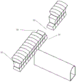
4a, 4b, 4c and 4d are respectively an overall schematic view of a tunnel-cross passage and a schematic view of excavation at different stages; wherein, fig. 4a is an overall schematic view of a tunnel-cross passage; fig. 4b is a schematic diagram of excavation of the first left pilot pit (1), the first right pilot pit (2), the second left pilot pit (3), the second right pilot pit (4) and the connecting channel of the tunnel section 10; fig. 4c is a schematic diagram of excavation of the first left pilot pit (1) of the tunnel section 10, the first right pilot pit (2), the second left pilot pit (3), the second right pilot pit (4), the third right pilot pit (6) of the tunnel section 10, and the lower step portion of the connecting channel; fig. 4d is a schematic diagram of excavation of the third left pilot pit (5), the third right pilot pit (6), the first core rock-soil mass (7), the second core rock-soil mass (8) and the third core rock-soil mass (9) of the tunnel section 10.
In the figure: 1, a waterproof curtain of a jet grouting pile; 2, filling a pile; 3, steel sheet piles; 4, a dewatering well outside the pit; 5, a dewatering well is arranged in the pit; 6, reinforcing the grids; 7, a vertical shaft; 8, primary support; 9, a transverse channel; 10 tunnel section 10;11 a transverse channel; 12 connecting the channels; 13 left pilot pit; 14 right pilot hole; 15 core rock-soil mass; 16 transverse channel upper steps; and 17, foundation pit.
The invention will be described in further detail with reference to the accompanying drawings
Referring to fig. 1, the upper foundation pit-lower tunnel combined construction structure in a saturated soft loess stratum comprises a foundation pit 17, wherein the bottom of the foundation pit 17 is communicated with a tunnel 11 through a vertical shaft 7, and a geogrid 6 is arranged above the bottom of the foundation pit 17; and the outer side of the foundation pit 17 is provided with a steel sheet pile 3, an in-pit dewatering well 5, a cast-in-place pile 2, a jet grouting pile waterproof curtain 1 and an out-pit dewatering well 4 from inside to outside.
The inner side of the foundation pit 17 is provided with a slope structure, the slope structure is arranged into a first slope and a second slope according to the depth, and a slope placing platform is arranged between the first slope and the second slope; the steel sheet piles 3 and the in-pit dewatering well 5 are arranged on a slope releasing platform between the slope surfaces of the second section and the first section; the cast-in-place pile 2, the jet grouting pile waterproof curtain 1 and the pit external dewatering well 4 are arranged at the beginning of the slope surface of the I section.
Referring to fig. 3, primary supports 8 are arranged above the bottom of the tunnel 11 along the circumferential direction of the tunnel, and transverse channels 9 are distributed between the primary supports 8 and the bottom of the tunnel 11.
Referring to fig. 4a, 4b, 4c, 4d, the tunnel profile 10 is divided into a left pilot hole 13, a right pilot hole 14, and a core rock mass 15.
A combined construction method of an upper foundation pit and a lower tunnel in a saturated soft loess stratum comprises the following steps:
step one, carrying out construction preparation work
1.3, carrying out site investigation and leveling and selecting proper construction machines;
1.4, carrying out technical pile test before the construction of the high-pressure jet grouting pile waterproof curtain, wherein the number of the test piles is not less than three, and each group comprises four piles.
Step two, construction of filling piles is carried out
2.1, pile position measurement and lofting are carried out according to a pile position plane arrangement diagram;
2.2, manufacturing a protective cylinder, and welding a stiffening rib on the upper and lower ports and the middle outer side of the protective cylinder respectively;
2.3, digging out an upper soil layer of a preset pile hole through a special drilling bucket, and putting into a pile casing;
2.4, positioning a drilling machine;
2.4.1, slowly putting the drill bit into the protective cylinder;
2.4.2, starting a winch to hoist the drilling platform, and placing a square block below the base of the drilling platform;
2.4.3, aligning the drilling machine to the drilled hole, and then installing a drilling disk;
2.5, drilling in the protective cylinder by a rotary drilling rig, wherein the inner diameter is 1100-1200 mm;
2.6, cleaning holes and placing a reinforcement cage;
2.7, pouring underwater concrete in the pile hole by a slurry down-going vertical lift pipe method, wherein the rising speed of the concrete surface is 2-2.2 m/min;
2.8, cleaning the site, and completing the construction of the support pile;
step three, waterproof curtain construction
3.1, positioning a drilling machine;
3.1.1, drilling a pipe down to a preset position;
3.1.2, performing clear water pressure test after the grouting pipe reaches a preset depth, gradually increasing the pressure in the pressure test process, reducing the frictional resistance and preventing the nozzle from being blocked;
3.1.3, after the pressure test is finished, starting to stir cement paste, wherein the water cement ratio is 1:1, the dosage of cement is 160-200 kg/m;
3.1.4, performing high-pressure grouting operation, wherein the grouting pressure is set to be 30-35 MPa;
3.1.5, performing high-pressure slurry injection from bottom to top, wherein the lifting speed of a spray pipe is not more than 15cm/min, and performing secondary spraying for 1-2 times;
3.1.6, after spraying to the designed height from bottom to top, timely pulling out the guniting pipe and finishing guniting;
3.1.7, cleaning the high-pressure pump, the slurry conveying pipeline, the grouting pipe and the spray head after the slurry spraying is finished;
step four, carrying out precipitation outside the pit
4.1, carrying out well point measurement and release according to a well position plane layout diagram and constructing a fence;
4.2, burying an opening protecting pipe, inserting the opening protecting pipe into an undisturbed soil layer, adopting cohesive soil to fill the outside of the pipe to prevent the outside of the pipe from being reverse-grouted, and enabling the upper part of the opening protecting pipe to be 0.1-0.3 m higher than the ground;
4.3, installing a drilling machine, wherein a drilling machine platform is required to be installed stably and horizontally and is aligned to the center of the hole;
4.4, drilling to form a hole, wherein the diameter of the hole is 800mm, drilling for 0.3-0.5 m more after drilling to a preset depth, ensuring the level of a drilling machine in the drilling process, ensuring the verticality of the drilled hole, and controlling the density of slurry to be 1.10-1.15;
4.5, when the hole is drilled to the top plate of the aquifer, adding clear water for mixing slurry, lifting the drill rod to be 0.5m away from the bottom of the hole for punching before drilling to the designed elevation for lifting the drill, and gradually adjusting the slurry density to 1.05;
4.6, installing an aligner when the well pipe is lowered so as to ensure that the water filter pipe can be centered, welding the well pipe firmly, vertically and watertight, and fixing and centering the wellhead after the well pipe is lowered to a preset depth;
4.7, before filling gravel, measuring the depth inside and outside the well pipe by using a measuring rope, wherein the difference does not exceed the length of the sedimentation pipe, the midway is not terminated in the filling process until the well pipe is put into a preset position, and the feeding amount is not less than 95% of the design amount;
4.8, sealing the well hole by using clay, mashing the clay before filling, and filling slowly along the periphery of the well pipe;
4.9, immediately putting the deep well submersible pump to the bottom of the well after the well is formed, laying a drainage pipeline, and starting pumping water after the pumping and drainage system is installed;
step five, excavation of the foundation pit 17, namely grading slope excavation and setting an excavation platform
5.1, removing obstacles in an excavation area, measuring and setting out;
5.2, adopting large-area slope cutting from top to bottom, wherein the excavation slope ratio is 1:1 to 1:2, excavating the top of the side slope to a slope placing platform in two stages;
5.3, checking the width of the slope platform in the excavation process, timely trimming if the width is insufficient, trimming once every 1m until the designed elevation is reached, uniformly performing slope trimming once after the excavation is finished, and checking the width and the elevation;
5.4, after the detection is correct, driving steel sheet piles into the foundation feet of the slope platform to serve as supports;
5.5, breaking the pile head of the cast-in-place pile, inserting the lower part of the steel framework into the cast-in-place pile, welding the steel framework with the main reinforcement of the cast-in-place pile, and pouring concrete after the completion;
5.6, excavating the slope placing platform to the bottom of the side slope, checking the width of the slope bottom in the excavating process, timely finishing if the width is insufficient, trimming once every 1m until the designed elevation is reached, and uniformly finishing the slope once after the excavating is finished and checking the width and the elevation;
sixthly, grid reinforcement is carried out at the bottom of the foundation pit 17
6.1, leveling a field after cleaning sundries on an operation surface, wherein the height difference is not more than 5cm;
6.2, laying the geogrid, and laying the geogrid to be smooth and straight;
6.3, connecting two adjacent geogrids in an overlapping manner, wherein the overlapping width is not less than 10cm, fixing the geogrids by using U-shaped nails, arranging seams in the non-main stress direction, and ensuring the binding distance to be within 1 m;
6.4, paving a gravel cushion layer after the geogrid is paved, repeatedly rolling to ensure compaction at intervals of not more than 48 hours, and leveling to ensure that the height difference is not more than 5cm after compaction is completed;
seventhly, carrying out water precipitation in the pit
7.1, carrying out well point measurement and release according to a well position plane layout diagram and constructing a fence;
7.2, burying an opening protecting pipe, inserting the opening protecting pipe into an undisturbed soil layer, adopting cohesive soil to fill the outside of the pipe to prevent the outside of the pipe from being reverse-grouted, and enabling the upper part of the opening protecting pipe to be 0.1-0.3 m higher than the ground;
7.3, installing a drilling machine, wherein a drilling machine platform is required to be installed stably and horizontally and is aligned to the center of the hole;
7.4, drilling to form a hole, wherein the diameter of the hole is 800mm, drilling for 0.3-0.5 m more after drilling to a preset depth, ensuring the level of a drilling machine in the drilling process, ensuring the verticality of the drilled hole, and controlling the density of slurry to be 1.10-1.15;
7.5, when the hole is drilled to the top plate of the aquifer, adding clear water for slurry mixing, lifting the drill rod to be 0.5m away from the bottom of the hole for punching before drilling to the designed elevation for lifting the drill, and gradually adjusting the slurry density to 1.05;
7.6, installing an alignment device when the well pipe is lowered so as to ensure that the water filter pipe can be centered, welding the well pipe firmly, vertically and watertight, and fixing and centering the wellhead after the well pipe is lowered to a preset depth;
7.7, before filling gravel, measuring the depth inside and outside the well pipe by using a measuring rope, wherein the difference does not exceed the length of the sedimentation pipe, the midway is not terminated in the filling process until the well pipe is put into a preset position, and the feeding amount is not less than 95% of the designed amount;
7.8, adopting clay to seal the well hole, mashing the clay before filling, and filling slowly along the periphery of the well pipe;
7.9, immediately putting the deep well submersible pump to the bottom of the well after the well is formed, laying a drainage pipeline, and starting pumping water after the pumping and drainage system is installed;
eighthly, carrying out vertical shaft construction and excavating transverse passages in the foundation pit 17
8.1, measuring and setting a vertical shaft well point according to a plane layout drawing and constructing a fence;
8.2, adopting short-section digging and building to carry out construction of a lock catch section, carrying out temporary support by driving an anchor rod, erecting a reinforcing mesh and C25 spraying concrete to form a sprayed anchor mesh support, wherein the lapping length of the reinforcing mesh through the reinforcing mesh is 20cm, the reinforcing mesh consists of phi 6-phi 10 reinforcing steel bars, the size of the mesh is 20 multiplied by 20 cm-25 multiplied by 25cm, the spray head is vertical to a spraying surface, and the spraying pressure is kept at 0.12-0.15 MPa;
8.3, binding reinforcing steel bars, supporting templates and pouring concrete after finishing;
8.4, installing temporary horizontal and oblique angle supports after the sprayed concrete reaches the strength, wherein the oblique angle supports are arranged at intervals of the horizontal steel grating;
8.5, after the steps are repeated to excavate to a preset elevation, spraying concrete, after final setting, laying a reinforcing mesh, erecting a grid steel frame, welding and connecting grids, and finally spraying concrete back cover;
8.6, after the construction of the vertical shaft is completed, constructing the cross position of the transverse channel and the vertical shaft, breaking a well wall at the position of the connecting channel, driving a glass fiber anchor rod to the outside of an excavation contour line for advanced support, performing primary concrete spraying on the excavated section, paving a reinforcing mesh sheet after the completion of the construction, erecting a grid steel frame, welding and connecting the grid and the reinforcing mesh sheet, and spraying concrete again on the reinforcing mesh sheet and the grid steel frame after the welding is completed;
8.7, repeating the steps until the connection between the transverse channel and the tunnel positive line is completed;
ninthly, excavating the tunnel main line
9.1, excavating a transverse channel upper step 16 of a transverse channel 11, and turning into a first right pilot pit (2) and a second right pilot pit (4) of a tunnel section 10 on the right side of a main line;
9.2, immediately carrying out primary support construction after the excavation is finished;
9.3, driving a glass fiber anchor rod outside the excavation contour surface, performing primary concrete spraying on the excavated section, erecting a grid steel frame and a reinforcing mesh and welding and connecting, and performing secondary concrete spraying to form a spray anchor net support after finishing the construction;
9.4, excavating a first right pilot tunnel (2) and a second right pilot tunnel (4) of the tunnel section 10 to a designed depth and constructing primary supports at the same time;
9.5, excavating a first core rock-soil body (7) and a second core rock-soil body (8) in the middle to the left pilot tunnel on the left side of the tunnel section 10 to form a connecting channel, and simultaneously adopting a glass fiber anchor rod to support the right pilot tunnel in advance in a small mileage direction and excavating;
9.6, after the excavation is finished, repeating the step 9.3 to finish primary support;
9.7, adopting a glass fiber anchor rod to support a guide pit on the left side of the section 10 of the tunnel in advance on the left side of the connecting channel, and excavating a first left guide pit (1) and a second left guide pit (3) of the section 10 of the tunnel;
9.8, adopting a glass fiber anchor rod to advance support the right side pilot tunnel of the tunnel section 10 on the right side of the connecting channel, and excavating a first right pilot tunnel (2) and a second right pilot tunnel (4);
9.9, immediately carrying out primary support construction after excavation is finished;
9.10, excavating the lower step parts of the left guide pit and the right guide pit simultaneously and applying primary support, wherein the excavating sequence is the same;
9.11, after the left and right pilot holes are excavated, driving glass fiber anchor rods into the tunnel in the same direction along the large and small process through the connecting channel, driving the glass fiber anchor rods outside the excavation contour surface, performing primary concrete spraying on the excavated section, erecting a grid steel frame and a reinforcing mesh and welding and connecting, and performing secondary concrete spraying to form a 'spray anchor net' support;
and step ten, backfilling the foundation pit 17.
The invention has good adaptability to the conditions of a foundation pit and a lower tunnel on a saturated soft loess stratum, the upper foundation pit 17 adopts a water-stop curtain to be combined with precipitation wells in and out of the pit, the water-stop curtain consists of jet grouting piles, the jet grouting piles are arranged in two rows, one row is respectively arranged outside the supporting piles and between the supporting piles, the pile bodies of the adjacent jet grouting piles are engaged, the underground water can be better intercepted, and simultaneously, the underground water can be effectively controlled by matching with the precipitation wells in and out of the pit. Foundation ditch 17 adopts hierarchical excavation, all struts the reinforcement after each grade excavation, and foundation ditch 17 bottom adopts geogrid to consolidate in order to deal with the basement uplift and gush water, gush sand etc. and consolidate and the precipitation effect is better. The tunnel main line is shifted to through the vertical shaft, the core rock-soil body is reserved, guide pits on two sides are preferably excavated, meanwhile, the glass fiber anchor rods are used for advance support, and the core rock-soil body is excavated and supported after excavation and support on two sides are completed, so that the deformation of the tunnel section 10 can be effectively controlled, the influence on the foundation pit 17 is reduced, the construction safety is ensured, and the influence between the foundation pit 17 and the tunnel is reduced.
Claims (7)
1. The utility model provides a go up foundation ditch-tunnel joint construction structure down in saturated soft loess stratum, includes foundation ditch (17), its characterized in that: the bottom of the foundation pit (17) is communicated with the tunnel (11) through a vertical shaft (7), and a geogrid (6) is arranged above the bottom of the foundation pit (17); and the outer side of the foundation pit (17) is provided with a steel sheet pile (3), an in-pit dewatering well (5), a cast-in-place pile (2), a jet grouting pile waterproof curtain (1) and an out-pit dewatering well (4) from inside to outside.
2. The upper foundation pit-lower tunnel combined construction structure in the saturated soft loess formation as claimed in claim 1, wherein: the inner side of the foundation pit (17) is provided with a slope structure, the slope structure is arranged into a first slope and a second slope according to the depth, and a slope placing platform is arranged between the first slope and the second slope; the steel sheet piles (3) and the in-pit dewatering well (5) are arranged on a slope releasing platform between the second-section slope surface and the first-section slope surface; the cast-in-place pile (2), the jet grouting pile waterproof curtain (1) and the pit external dewatering well (4) are arranged at the beginning of the slope surface of the I section.
3. The upper foundation pit-lower tunnel combined construction structure in the saturated soft loess formation as claimed in claim 1, wherein: the tunnel is characterized in that a primary support (8) is arranged above the bottom of the tunnel (11) along the circumferential direction of the tunnel, and transverse channels (9) are distributed between the primary support (8) and the bottom of the tunnel (11).
4. A combined construction method of an upper foundation pit and a lower tunnel in a saturated soft loess stratum is characterized by comprising the following steps: the method specifically comprises the following steps:
step one, carrying out construction preparation work
1.1, carrying out site investigation and leveling and selecting proper construction machines;
1.2, carrying out technological pile testing before the construction of the high-pressure jet grouting pile waterproof curtain, wherein the number of the pile testing is not less than three groups, and each group comprises four piles;
step two, carrying out cast-in-place pile construction
2.1, pile position measurement and lofting are carried out according to the pile position plane layout;
2.2, manufacturing a protective cylinder, and arranging stiffening ribs at the upper and lower ports and the middle outer side of the protective cylinder;
2.3, digging out an upper soil layer of a preset pile hole through a drilling bucket, and putting the pile casing into the pile casing;
2.4, positioning a drilling machine;
2.4.1, slowly putting the drill bit into the protective cylinder;
2.4.2, hoisting the drill plate, and filling square wood below the base of the drill plate;
2.4.3, aligning the drilling machine to the drilled hole and installing a drilling disk;
2.5, drilling in the protective cylinder, wherein the diameter of the hole is 1100-1200 mm;
2.6, cleaning holes and placing a reinforcement cage;
2.7, pouring underwater concrete in the pile hole, wherein the rising speed of the concrete surface is 2-2.2 m/min;
2.8, cleaning the site, and completing the construction of the support pile;
step three, waterproof curtain construction
3.1, positioning a drilling machine;
3.1.1, drilling a pipe down to a preset position;
3.1.2, carrying out clear water pressure test after the grouting pipe reaches a preset depth, wherein the pressure is gradually increased in the pressure test process, so that the frictional resistance is reduced, and the nozzle is prevented from being blocked;
3.1.3, after the pressure test is finished, cement paste is stirred, the water cement ratio is equal, and the cement consumption is 160-200 kg/m;
3.1.4, performing high-pressure grouting operation, wherein the grouting pressure is set to be 30-35 MPa;
3.1.5, performing high-pressure slurry injection from bottom to top, wherein the lifting speed of a spray pipe is not more than 15cm/min, and performing secondary spraying for 1-2 times;
3.1.6, after spraying to the designed height from bottom to top, timely pulling out the guniting pipe and finishing guniting;
3.1.7, cleaning the high-pressure pump, the slurry conveying pipeline, the grouting pipe and the spray head after the slurry spraying is finished;
step four, carrying out precipitation outside the pit;
4.1, carrying out well point measurement and release according to a well position plane layout diagram and constructing a fence;
4.2, burying an opening protecting pipe, inserting the opening protecting pipe into an undisturbed soil layer, adopting cohesive soil to fill the outside of the pipe to prevent the outside of the pipe from being reverse-grouted, and enabling the upper part of the opening protecting pipe to be 0.1-0.3 m higher than the ground;
4.3, installing a drilling machine, wherein a drilling machine platform is required to be installed stably and horizontally and is aligned to the center of the hole;
4.4, drilling to form a hole, drilling for 0.3-0.5 m more after drilling to a preset depth, ensuring the level of a drilling machine in the drilling process, ensuring the verticality of the drilled hole, and controlling the density of slurry to be 1.10-1.15;
4.5, when drilling to a top plate of a water-bearing stratum, adding clear water for mixing slurry, drilling to a designed elevation, before drilling, lifting a drill rod to a position 0.5-1.0 m away from the bottom of a hole for punching, and gradually adjusting the slurry density to 1.00-1.05;
4.6, installing an aligner when the well pipe is lowered so as to ensure that the water filter pipe can be centered, welding the well pipe firmly, vertically and watertight, and fixing and centering the wellhead after the well pipe is lowered to a preset depth;
4.7, before filling gravel, measuring the depth inside and outside the well pipe by using a measuring rope, wherein the difference does not exceed the length of the sedimentation pipe, the midway is not terminated in the filling process until the well pipe is put into a preset position, and the feeding amount is not less than 95 percent of the design amount;
4.8, sealing the well hole by using cohesive soil, mashing the clay before filling, and filling slowly along the periphery of the well pipe;
4.9, immediately putting the deep well submersible pump to the bottom of the well after the well is formed, laying a drainage pipeline, and starting pumping water after the pumping and drainage system is installed;
step five, excavating foundation pit 17
5.1, clearing obstacles in an excavation area and carrying out measurement and setting-out;
5.2, adopting large-area slope cutting from top to bottom, wherein the excavation slope ratio is 1:1 to 1:2, excavating the top of the side slope to a slope-caving platform in a grading manner;
5.3, checking the width of the slope platform in the excavation process, timely trimming if the width is insufficient, sequentially trimming to the designed elevation every 1-2 m, uniformly trimming the slope after the excavation is finished, and checking the width and the elevation;
5.4, after the slope is checked to be correct, driving steel sheet piles into the foundation of the slope platform to serve as supports;
5.5, breaking the pile head of the cast-in-place pile, inserting the lower part of the steel framework into the cast-in-place pile, welding the steel framework with the main reinforcement of the cast-in-place pile, and pouring concrete after the completion;
5.6, excavating the slope placing platform to the bottom of the side slope, checking the width of the slope bottom in the excavating process, timely finishing if the width is insufficient, trimming to the elevation, and uniformly finishing the slope once and checking the width and the elevation after the excavating is finished;
sixthly, grid reinforcement is carried out at the bottom of the foundation pit 17
6.1, leveling a field after cleaning sundries on an operation surface, wherein the height difference is not more than 5cm;
6.2, laying the geogrid, and laying the geogrid to be smooth and straight;
6.3, connecting two adjacent geogrids in a lap joint mode, wherein the lap joint width is not less than 10cm, fixing the geogrids, and arranging seams in the non-main stress direction;
6.4, paving a broken stone cushion layer after the geogrid is paved, repeatedly rolling to ensure compaction at intervals of not more than 48 hours, and leveling to ensure that the height difference is not more than 5cm after compaction is finished;
seventhly, carrying out water precipitation in the pit
7.1, carrying out well point measurement and release according to a well position plane layout diagram and constructing a fence;
7.2, burying an opening protecting pipe, inserting the opening protecting pipe into an undisturbed soil layer, adopting cohesive soil to fill the outside of the pipe to prevent the outside of the pipe from being reverse-grouted, and enabling the upper part of the opening protecting pipe to be 0.1-0.3 m higher than the ground;
7.3, installing a drilling machine, wherein a drilling machine platform is required to be installed stably and horizontally and is aligned to the center of the hole;
7.4, drilling to form a hole, drilling for 0.3-0.5 m more after drilling to a preset depth, ensuring the level of a drilling machine in the drilling process, ensuring the verticality of the drilled hole, and controlling the density of slurry to be 1.10-1.15;
7.5, when a hole is drilled to the top plate of the aquifer, adding clear water for mixing slurry, drilling to a designed elevation, before the drill is lifted, lifting the drill rod to a position 0.5-1.00 m away from the bottom of the hole for punching, and gradually adjusting the slurry density to 1.0-1.05;
7.6, installing an aligner when the well pipe is lowered so as to ensure that the water filter pipe can be centered, welding the well pipe firmly, vertically and watertight, and fixing and centering a wellhead after the well pipe is lowered to a preset depth;
7.7, before filling gravel, measuring the depth inside and outside the well pipe by using a measuring rope, wherein the difference value does not exceed the length of the sedimentation pipe, the midway is not terminated in the filling process until the well pipe is put into a preset position, and the feeding amount is not less than 95% of the design amount;
7.8, adopting clay to seal the well hole, mashing the clay before filling, and filling slowly along the periphery of the well pipe;
7.9, immediately putting the deep well submersible pump into the well bottom after the well is formed, laying a drainage pipeline, and starting pumping water after the pumping and drainage system is installed;
eighthly, carrying out vertical shaft construction and excavating transverse passages in the foundation pit 17
8.1, measuring and releasing the shaft well points according to the plane layout drawing and constructing a fence;
8.2, performing lock catch section construction by adopting short-section digging and building, and performing temporary support by driving an anchor rod, erecting a reinforcing mesh and spraying concrete to form an anchor-spraying mesh support, wherein the reinforcing mesh consists of reinforcing steel bars with the diameter of 6-10 mm, the size of the mesh is 20 multiplied by 20 cm-25 multiplied by 25cm, the spray head is vertical to a spray surface, and the spraying pressure is kept at 0.12-0.15 MPa;
8.3, binding reinforcing steel bars, supporting templates and pouring concrete after finishing;
8.4, installing temporary horizontal and oblique angle supports after the sprayed concrete reaches the strength, wherein the oblique angle supports are arranged at intervals of the horizontal steel grating, and the oblique angle supports form an angle of 45-60 degrees with the well wall;
8.5, after the steps are repeated to excavate to a preset elevation, firstly spraying concrete with the height of 25mm-30mm, after final setting, paving a reinforcing mesh sheet, erecting a grid steel frame, enabling the distance between grids in the shaft bottom to be 800-1000 mm, adopting welding connection among grids, and finally spraying concrete again to seal the bottom;
8.6, after the construction of the vertical shaft is completed, constructing the cross position of the transverse channel and the vertical shaft, breaking a well wall at the position of the connecting channel, driving a glass fiber anchor rod to the excavation contour line for advanced support, performing primary concrete spraying on the excavated section, paving a reinforcing mesh after the completion, erecting a grid steel frame, welding and connecting the grid and the reinforcing mesh, and re-spraying concrete on the reinforcing mesh and the grid steel frame after the completion of welding;
8.7, repeating the steps until the connection between the transverse channel (11) and the tunnel main line is completed;
ninthly, excavating the tunnel main line
9.1, excavating a transverse channel upper step (16) of a transverse channel (11), and turning into a first right pilot pit (2) and a second right pilot pit (4) of a tunnel section (10) on the right side of a main line;
9.2, immediately carrying out primary support construction after the excavation is finished;
9.3, driving a glass fiber anchor rod outside the excavation contour surface, performing primary concrete spraying on the excavated section, erecting a grid steel frame and a reinforcing mesh and welding and connecting, and performing secondary concrete spraying to form a spray anchor net support after finishing the construction;
9.4, continuously excavating the first right pilot tunnel (2) and the second right pilot tunnel (4) of the tunnel section 10 to a design footage and constructing primary support at the same time;
9.5, excavating a first core rock-soil body (7) and a second core rock-soil body (8) in the middle to a left pilot tunnel at the designed footage position to the left side of the tunnel section (10) to form a connecting channel (12), and meanwhile adopting a glass fiber anchor rod to advance support the right pilot tunnel in the small mileage direction and excavating;
9.6, after the excavation is finished, repeating the step 9.3 to finish primary support;
9.7, adopting a glass fiber anchor rod to support a guide pit on the left side of the tunnel section (10) in advance on the left side of the connecting channel (12), and excavating a first left guide pit (1) and a second left guide pit (3) on the tunnel section (10);
9.8, adopting a glass fiber anchor rod to advance and support a right guide pit of the tunnel section (10), a first right guide pit (2), a second right guide pit (4) and a third right guide pit (6) on the right side of the connecting channel and excavating;
9.9, immediately carrying out primary support construction after the excavation is finished;
9.10, excavating the lower step parts of the left guide pit and the right guide pit simultaneously and applying primary support, wherein the excavating sequence is the same;
9.11, after the left and right guide pits are excavated, driving glass fiber anchor rods into the left and right directions of the tunnel through a connecting channel (12), driving the glass fiber anchor rods outside the excavation contour surface, performing primary concrete spraying on the excavated section, erecting a grid steel frame and a reinforcing mesh sheet and welding the grid steel frame and the reinforcing mesh sheet, and performing secondary concrete spraying to form a 'spray anchor mesh' support;
and step ten, backfilling the foundation pit (17).
5. The upper foundation pit-lower tunnel combined construction method in the saturated soft loess formation as claimed in claim 4, wherein: and in the second step 2.7, adopting a slurry down-riser pipe method for underwater concrete in the cast-in-place pile hole.
6. The upper foundation pit-lower tunnel combined construction method in the saturated soft loess formation as claimed in claim 4, wherein: in the third step 3.1.3, the water-cement ratio of the used cement paste is 1:1.
7. the upper foundation pit-lower tunnel combined construction method in the saturated soft loess formation as claimed in claim 4, wherein: and fifthly, trimming the edges in the steps 5.3 and 5.6, wherein the trimming side is up to the designed elevation every 1 m.
Priority Applications (1)
| Application Number | Priority Date | Filing Date | Title |
|---|---|---|---|
| CN202211138387.8A CN115977102A (en) | 2022-09-19 | 2022-09-19 | Upper foundation pit-lower tunnel combined construction structure and construction method in saturated soft loess stratum |
Applications Claiming Priority (1)
| Application Number | Priority Date | Filing Date | Title |
|---|---|---|---|
| CN202211138387.8A CN115977102A (en) | 2022-09-19 | 2022-09-19 | Upper foundation pit-lower tunnel combined construction structure and construction method in saturated soft loess stratum |
Publications (1)
| Publication Number | Publication Date |
|---|---|
| CN115977102A true CN115977102A (en) | 2023-04-18 |
Family
ID=85960046
Family Applications (1)
| Application Number | Title | Priority Date | Filing Date |
|---|---|---|---|
| CN202211138387.8A Pending CN115977102A (en) | 2022-09-19 | 2022-09-19 | Upper foundation pit-lower tunnel combined construction structure and construction method in saturated soft loess stratum |
Country Status (1)
| Country | Link |
|---|---|
| CN (1) | CN115977102A (en) |
-
2022
- 2022-09-19 CN CN202211138387.8A patent/CN115977102A/en active Pending
Similar Documents
| Publication | Publication Date | Title |
|---|---|---|
| CN104612162B (en) | A kind of Deep Foundation Pit of Metro Stations excavation construction method | |
| CN108442382B (en) | In-situ protection and enclosure soil-retaining structure for pressure pipeline crossing deep foundation pit and construction method | |
| CN210013697U (en) | Construction structure of near-penetrating building of underground excavation section of subway station entrance and exit | |
| CN111101540B (en) | Construction method for passing existing electric power tunnel on open cut tunnel | |
| LU500273B1 (en) | New comprehensive dewatering and drainage method and drainage device for mudstone subway station | |
| CN108316339A (en) | A kind of construction method of water penetration geology large size arch bridge base | |
| CN112663625A (en) | Construction and protection method for shallow-buried bias-pressure weak surrounding rock tunnel portal in alpine region | |
| CN106760620A (en) | A kind of utilization open caisson increases the construction method for building the underground space under existing building | |
| CN107964971B (en) | A kind of precipitation method of the subway station using the construction of PBA engineering method | |
| US4496268A (en) | Method and apparatus for constructing reinforced concrete walls in the earth | |
| CN114411756A (en) | Construction method and construction device for water-rich sand layer subway station open excavation foundation pit without precipitation | |
| CN109339079A (en) | A kind of foundation pit water-stopping system and its construction technology close to river permeable stratum | |
| CN115539048A (en) | Construction method for shallow-buried bias tunnel portal | |
| CN114575355A (en) | Soil protection and descent construction method | |
| CN111560964B (en) | Construction method of rear anti-seepage system of foundation pit | |
| CN209260739U (en) | A kind of foundation pit water-stopping system close to river permeable stratum | |
| CN110762286A (en) | Drainage pipe network artificial pipe jacking construction process | |
| CN115162345A (en) | Yangtze river flood plain super-large deep foundation pit earthwork excavation tissue and construction method | |
| CN114922195A (en) | Construction method of soft soil deep and large foundation pit adjacent to protected object | |
| CN112112657B (en) | New construction method for digging and building inclined shaft of coal mine | |
| CN113123358A (en) | Ship pool deformation prevention structure under coal mining differential settlement effect and construction method | |
| CN115977102A (en) | Upper foundation pit-lower tunnel combined construction structure and construction method in saturated soft loess stratum | |
| CN110984143A (en) | Prefabricated rectangular slide-resistant pile retaining wall and construction method thereof | |
| CN111663538A (en) | Construction method for deep foundation pit miniature steel pipe pile support in complex geology of clearance limited area | |
| CN111042144A (en) | Excavation method for foundation pit of underground beam under condition of continuous flow of riverway in cold region |
Legal Events
| Date | Code | Title | Description |
|---|---|---|---|
| PB01 | Publication | ||
| PB01 | Publication | ||
| SE01 | Entry into force of request for substantive examination | ||
| SE01 | Entry into force of request for substantive examination |