CN1159207C - cleaning solution dilution and dispensing system - Google Patents
cleaning solution dilution and dispensing system Download PDFInfo
- Publication number
- CN1159207C CN1159207C CNB00812048XA CN00812048A CN1159207C CN 1159207 C CN1159207 C CN 1159207C CN B00812048X A CNB00812048X A CN B00812048XA CN 00812048 A CN00812048 A CN 00812048A CN 1159207 C CN1159207 C CN 1159207C
- Authority
- CN
- China
- Prior art keywords
- bottle
- valve
- liquid
- assembly
- driving device
- Prior art date
- Legal status (The legal status is an assumption and is not a legal conclusion. Google has not performed a legal analysis and makes no representation as to the accuracy of the status listed.)
- Expired - Fee Related
Links
Images


Classifications
-
- B—PERFORMING OPERATIONS; TRANSPORTING
- B67—OPENING, CLOSING OR CLEANING BOTTLES, JARS OR SIMILAR CONTAINERS; LIQUID HANDLING
- B67D—DISPENSING, DELIVERING OR TRANSFERRING LIQUIDS, NOT OTHERWISE PROVIDED FOR
- B67D7/00—Apparatus or devices for transferring liquids from bulk storage containers or reservoirs into vehicles or into portable containers, e.g. for retail sale purposes
- B67D7/06—Details or accessories
- B67D7/78—Arrangements of storage tanks, reservoirs or pipe-lines
-
- B—PERFORMING OPERATIONS; TRANSPORTING
- B67—OPENING, CLOSING OR CLEANING BOTTLES, JARS OR SIMILAR CONTAINERS; LIQUID HANDLING
- B67D—DISPENSING, DELIVERING OR TRANSFERRING LIQUIDS, NOT OTHERWISE PROVIDED FOR
- B67D7/00—Apparatus or devices for transferring liquids from bulk storage containers or reservoirs into vehicles or into portable containers, e.g. for retail sale purposes
- B67D7/02—Apparatus or devices for transferring liquids from bulk storage containers or reservoirs into vehicles or into portable containers, e.g. for retail sale purposes for transferring liquids other than fuel or lubricants
- B67D7/0205—Apparatus or devices for transferring liquids from bulk storage containers or reservoirs into vehicles or into portable containers, e.g. for retail sale purposes for transferring liquids other than fuel or lubricants by manually operable pumping apparatus
-
- B—PERFORMING OPERATIONS; TRANSPORTING
- B67—OPENING, CLOSING OR CLEANING BOTTLES, JARS OR SIMILAR CONTAINERS; LIQUID HANDLING
- B67D—DISPENSING, DELIVERING OR TRANSFERRING LIQUIDS, NOT OTHERWISE PROVIDED FOR
- B67D7/00—Apparatus or devices for transferring liquids from bulk storage containers or reservoirs into vehicles or into portable containers, e.g. for retail sale purposes
- B67D7/06—Details or accessories
- B67D7/74—Devices for mixing two or more different liquids to be transferred
- B67D7/741—Devices for mixing two or more different liquids to be transferred mechanically operated
Abstract
A dilution control system (100) for diluting a first fluid with a second fluid and dispensing diluted fluid is disclosed. The dilution control system includes a bottle (150) that is adapted for receiving a quantity of the first fluid. A valve insert (170) is disposed in the opening of the bottle and includes at least one valve for controlling the flow of fluid from the bottle and an air vent.
Description
Technical field
The present invention relates to dilute control system, relate to the system that is used to dilute and prepare the concentrating chemical cleaning liquid more specifically.Dilution control system of the present invention comprises that detouchable is installed in the chemical souring liquid container on the plastics device for formulating of connecting with the water source.This device for formulating comprises that the mechanical device that the external control switch is used for starting device for formulating allows chemical cleaning solution to discharge from container.When switch is activated, advance device for formulating at about same time current, the dilute aqueous solution of chemical cleaning solution flows out device for formulating.So dilute aqueous solution receives with bottle or batch can and is used in, as, the assigned object surface cleaned as floor and bathroom fittings.
Background technology
The dilution control system generally is used for the clean and maintenance industry, is used for dilution and preparation chemical cleaning solution.This system allows the clean and maintenance personnel to be used to come from the economy way of the chemical cleaning solution of buying conc forms, dilutes and the preparation cleaning liquid in the place that they need then.Therefore, the dilution control system is accurately diluted and prepared cleaning liquid is very important, reaches thus to be used to clean the needed chemical concentrations of purpose, and the ground that avoids waste excessively uses the concentrating chemical cleaning liquid.
In addition, because when concentrating chemical cleaning liquid when the clean and maintenance workman directly contacts with the cleaning liquid goods usually is harmful to them, so the dilution control system is diluted safely and prepared cleaning liquid also is very important, thereby eliminate any deletrious disperse or the leakage of the cleaning liquid that concentrates and/or diluted.At last, because clean and maintenance workpeople typically has a series of skill level as a group, from very skilled clean and maintenance engineer to unskilled Custodial Worker, so convenient and be easy to use just very important for the dilution control system, avoid the measurement and/or the operating sequence of any complexity thus.
In the clean and maintenance industry, there has been multiple systems to be used for dilution control.There are several such dilution control system to sell by the BUTCHER company of Massachusetts, United States Marlborough.For example, the PIPELINE board enrichedmaterial bottle that BUTCHER company sells, the concentrating chemical cleaning liquid that it has built-in measuring chamber to be used for preparing accurately measuring amount are used for the dilution of carrying out subsequently.In addition, BUTCHER company sells KDS board keg conveying system, it comprise the concentrating chemical cleaning liquid of measuring amount be used for subsequently in the dilution of adding the logical sequence keg.
Though PIPELINE board enrichedmaterial bottle and KDS board conveying system all successfully have been used in accurately, safety and dilute expediently and prepare the concentrating chemical cleaning liquid, these dilution control system have a defective to be that they are mainly useful when small size cleans application.
BUTTCHER company also sells COMMAND CENTER board dilution control system, utilizes Venturi effect that the concentrating chemical cleaning liquid is sucked in the current.Especially, COMMAND CENTER board dilution control system comprises the eductor that has side tubule with holes.When flowing through tubule, water produces vacuum, in concentrating chemical cleaning liquid induction pipe in this hole.Eductor also comprises the nozzle that has multiple size hole, is used to control the amount that is inhaled into also diluted concentrating chemical cleaning liquid.Thereby the chemical cleaning solution quilt of needed concentration rapidly and preparation easily comes out to enter into bottle and bucket is prepared against use subsequently.
Be used for safety in using and dilute expediently and prepare the concentrating chemical cleaning liquid though COMMAND CENTER board dilution control system has also successfully been cleaned in large volume, the purpose of using Venturi effect absorption concentrating chemical cleaning liquid to reach dilution in the current can not provide the accuracy rate of requirement sometimes.
Authorize in June 29 nineteen ninety-five in the US Patent the 5th, 425, No. 404 (No. 404 patents) of Dyer, described and be used for obtaining liq and the gravity feed fluid compounding system of a kind of liquid and another kind of liquid mixing.According to this patent, the liquid dosage system comprises the bottle that holds some liquid, and bottle reverses and is connected with the dispenser assembly.So structure is so that when bottle is connected with system in this liquid dosage system, and bottle is opened and allows flow of liquid to cross system, and shuts bottle when bottle is not connected with system.Second kind of liquid, for example, water can be imported into system and first kind of liquid, as the concentrating chemical cleaning liquid, mixes, and dilutes first kind of liquid in a controlled manner.
Yet the compounding system of describing in No. 404 patents also has some shortcomings.For example, this compounding system uses the rotating operation of the bottle that the concentrating chemical cleaning liquid is housed that liquid is flowed out from bottle.The inexperienced operator must rotate fully thus bottle to " opening " or " releasing " position with dilution and preparation concentrating chemical cleaning liquid, rotate fully then bottle to " pass " or " current limliting " position to prevent cleaning liquid any further unnecessary outflow from bottle.Yet, the inexperienced operator, particularly those only have low level of skill, may fail bottle is rotated back into the position of current limliting behind the preparation cleaning liquid, thereby cause cleaning liquid to spill from the bottle of counter-rotating.Therefore the compounding system of No. 404 patent description lacks the desired height facility of present clean and maintenance workman.
Therefore have can be used for accurately, safety and dilute easily and the dilution control system of preparing the concentrating chemical cleaning liquid will be desirable.Such system should be able to be suitable for using when the large volume cleaning operation.Have and to prevent that concentrating chemical cleaning liquid dilution control system of excessive use and/or leakage in system from also will be desirable.
Summary of the invention
Other shortcomings aforementioned and prior art are overcome according to dilution control system of the present invention.In preferred embodiments, the dilution control system comprises the bottle that is applicable to a certain amount of first kind of liquid of reception.This bottle has at least one to be installed in first valve that bottleneck is used to control the flow velocity that first kind of liquid flows out from bottle, in the position that this first valve tends to close.The dilution compounding system comprises that also dilution and dispenser assembly are used for supporting bottle when diluting and preparing first kind of liquid.This dilution/dispenser assembly comprises and has the housing of liquid header that at least one has receiving port and preparation mouthful; Under the situation of bottle aperture downward alignment liquid catcher receiving port, on housing, connect and support the top bench board of bottle; And, the concetrated pipe assembly comprises that at least one is used to receive the inlet of second kind of liquid, the outlet that at least one is communicated with inlet, this exports downward alignment liquid catcher receiving port, at least one is communicated with the driving device that first valve that is used for placing bottleneck moves to open position with inlet, this driving device is crossed the concetrated pipe assembly by second kind of flow of liquid and is triggered, also have at least one second valve to be used to control that second kind of liquid export from entering the mouth and driving device mobile, position that this second valve tends to close and the position that can be exchanged into out.
The water valve control setup is used to allow the operator to change second valve on the concetrated pipe assembly to the position of opening and closing.In addition, bayonet lock be used to be connected bottle and dilution/dispenser assembly top bench board.In addition, first valve places bottleneck and valve insert to combine, and preferably further comprises vent.
When the position that second valve is converted to out, second kind of liquid can flow to the outlet of concetrated pipe assembly and enter liquid header from inlet.In addition, second kind of liquid can trigger driving device, makes first kind of flow of liquid feed liquor body catcher and second kind of liquid mixing in the bottle thus, passes through the preparation mouth prepared and diluted liquid of liquid header subsequently.Easily, the dilution control system only allows first kind of liquid to flow out from bottle when second kind of flow of liquid crossed the concetrated pipe assembly, thereby has in fact got rid of the undesigned excessive first kind of liquid that uses and leak.For example, first kind of liquid can be concentrating chemical cleaning liquid and second kind of liquid is water.
Also have further purpose and advantage will consider subsequently description and drawing after become obvious.
Description of drawings
The present invention will with reference to below very detailed description and pay with drawing after better understand.
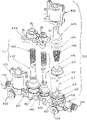
Figure 1A is the isometric view according to dilution control system of the present invention;
Figure 1B is the exploded drawings as the dilution control system of Figure 1A, displaying be the shell of bench board partial sum bottom, top;
Fig. 1 C is the isometric view according to the top bench board part of dilution control system of the present invention;
Fig. 1 D is an isometric view of showing the water concetrated pipe assembly that is placed in one according to top of the present invention bench board;
Fig. 2 shows the exploded drawings of liquid header and the exploded drawings of water valve control setup according to dilution control system lower case of the present invention;
Fig. 3 is the exploded drawings according to the part of top of the present invention bench board, shows the bayonet lock that the bottle be used to make the dress concentrate is connected;
Fig. 4 is the exploded drawings according to a water concetrated pipe assembly part of the present invention;
Fig. 5 is the exploded drawings according to water concetrated pipe assembly another part of the present invention;
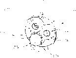
Fig. 6 A is the top plan view of the part of water concetrated pipe assembly as shown in Figure 5;
Fig. 6 B is the section drawing of the part of water concetrated pipe assembly as shown in Figure 6A;
Fig. 7 A is the isometric view according to valve insert of the present invention;
Fig. 7 B is an isometric view of showing a pair of chemical substance valve and air extractor vent according to valve insert of the present invention;
Fig. 8 is the exploded drawings of the valve insert shown in Fig. 7 A;
Fig. 9 A is the isometric view according to concentrate bottle of the present invention;
Fig. 9 B is the top plan view of the bottle shown in Fig. 9 A;
The detail drawing of the bottle of Fig. 9 C shown in Fig. 9 B.
The specific embodiment
What Figure 1A showed is according to dilution control system 100 of the present invention.This dilution control system 100 comprises top bench board 110, shown in Figure 1A, 1B and 1C.Top bench board 110 comprises water concetrated pipe assembly 200 (seeing Figure 1B, 1D, 4,5,6A and 6B), and it is connected with top bench board 110 and is communicated with the water source (not shown).Dilution control system 100 also comprises lower case 120, as shown in Figure 2.Lower case 120 comprises liquid header 280 and water valve control setup 290.
Bottle 150 has a key 152 from the radial outside protrusion of bottle 150 (seeing Fig. 9 B and 9C) neck (unnumbered) at least.When being connected when bottle 150 counter-rotatings and with dilution control system 100, key 152 is accepted by the cooresponding with it keyway 112 that the receiving port 118 (seeing Fig. 1 C) from top bench board 110 outwards extends.In addition, the crestal line 115 (seeing Fig. 9 B and 9C) that forms when at least one bayonet lock 114 that combines with top table assembly 110 (seeing Fig. 1 C and 3) with at bottle 150 necks is when being connected, and bottle 150 becomes fully and dilutes control system 100 and be connected.Button 116 (seeing Fig. 1 C, 1D and 3) effectively with top table assembly 110 and bayonet lock 114 combinations, be used for bottle is broken away from from bayonet lock 110 fast, system operators can be removed bottle 150 from the top bench board 110 of dilution control system 100.
On bottle 150 with the fixing characteristics of key 152 allow easily the user exactly the bottle 150 of positioning belt valve insert 170 with respect to the position of dilution control system 100.Especially, with the fixing characteristics of key 152 make place bottle 150 apertures (unnumbered) valve insert 170 exactly and the bottle valve controling rod 202 and 204 (seeing Fig. 1 D) that combines with water concetrated pipe assembly 200 location, guarantee that thus bottle valve controling rod 202 and 204 cooperated with valve insert 170 exactly in the operating period of dilution control system 100.
More particularly, bottle valve controling rod 202 cooperates with discharge orifice 572 and air extractor vent 576 (seeing Fig. 7 B) on the valve insert 170 simultaneously.As selection, another bottle valve controling rod 204 cooperates with another discharge orifice 574 and air extractor vent 576 (seeing Fig. 7 B) on the valve insert simultaneously.In addition, in illustrative embodiment, discharge orifice 574 provides low flow velocity for the concentrating chemical cleaning liquid of bottle 150; Discharge orifice 572 provides high flow rate for the concentrate of bottle 150.
Therefore, bottle valve controling rod 202 and 204 can be advantageously used in selecting the low flow velocity or the high flow rate of the liquid that flows out from same bottle 150.For example, system operators can be selected the cleaning liquid perfusion small container of low flow velocity with dilution, as, spray bottle.As selection, the user can select high flow rate to fill bulk container with the cleaning liquid of dilution, as, well-bucket.
Water valve control setup 290 in the lower case 120 comprises rotatable control dial 130 (see figure 2)s, is used to start the operation of bottle valve controling rod 202 and 204.When control dial 130 by rotation direction, to the primary importance (see figure 2), a bottle valve controling rod 202 is activated as clockwise direction; Be screwed into and work as control dial 130, to second place (not shown), another bottle valve controling rod 204 is activated as anticlockwise direction.Therefore, control dial 130 can be used for selecting easily needed flow velocity by the dilution cleaning liquid that dilutes the control system preparation by system operators.In addition, the off-position in the middle of control dial 130 is screwed into, bottle valve controling rod 202 and 204 is all disabled.
Bottle 150 can use any suitable material such as polymeric material to make with the method for any routine (as, injection moulding).Dilution top bench board 110 of control system 100 and lower case 120 also can any suitable material be anti-makes towards the property plastics with the method for any routine (as, injection moulding) use.It should be noted that the material of selecting to be used to make bottle 150, top bench board 110 and lower case 120 must adapt to the concentrating chemical liquid phase that will be prepared from bottle 150.
Be the exploded drawings of the part of the water concetrated pipe assembly 200 in the top bench board 110 as shown in Figure 4.Especially, water concetrated pipe assembly 200 comprises a pair of reversed liquid inlet 206 (seeing Fig. 1 C, 1D, 5,6A and 6B), Liquid valve assembly 208 and 209 (seeing Fig. 1 C, 1D and 5), liquid diaphragm assembly 210 and 211 (seeing Fig. 1 D and 5), bottle valve controling rod 202 and 204, and be used for the outlet 212 and 213 (see figure 4)s of output liquid, preferably the water that comes from the water source is used to dilute the concentrating chemical liquid from bottle 150.
Reversed liquid inlet 206 is connected by common tubular conduit 214, and this makes dilution control system 100 can be used as independently unit use or uses as one of one group of same dilution control system 100.For example, when dilution control system 100 is used as separate unit, liquid inlet 206 is by being connected with the water source as flexible pipe (not shown) or other suitable connection modes, and another liquid inlet preferably is covered, as with nut 217 (seeing Figure 1A and 1B).And when dilution control system 100 was used in one group of dilution control system 100, a liquid inlet 206 can be connected with the water source as mentioned above, and another liquid inlet 206 is connected with in succession dilution control system 110.Like this, a plurality of dilution control system 100 just is linked together and uses the operation of same water source easily.At this moment not connection liquid inlet 206 in the dilution control system 100 of set of systems 100 ends preferably covers with nut 217.
As mentioned above, lower case 120 comprises liquid header 280 and water valve control setup 290, the control dial 130 of water valve control setup 290 is used for by starting the operation of bottle valve controling rod 202 and 204 by system operators, selects the flow velocity of the cleaning liquid of needed dilution from 100 outflows of dilution control system.As shown in Figure 2, water valve control setup 290 further comprises the knob seat ring 294 that combines with control dial 130 and control transmission shaft 296, and knob seat ring 294 then links with water valve driving device 298.Control transmission shaft 296 and water valve driving device 298 all are enclosed in the lower case 120, and water valve driving device 298 pivotally is installed in lower case 120 inside faces, and control transmission shaft 296 is axially installed with knob seat ring 294 outside lower case 120 and is connected.
Therefore, when control dial 130 (see figure 2)s as described above forward primary importance to, knob seat ring 294, control transmission shaft 296 and water valve driving device 298 resemble an integral body and rotate thereupon, make operating surface 297 closed contacts of water valve driving device 298 thus and drive water valve control stalk 205 (being) shown in Fig. 1 D, thereby start bottle valve controling rod 202 (also being) shown in Fig. 1 D at its braking position at its braking position.As selection, when control dial 130 forwards the second place to as previously described, water valve control setup 290 makes another operating surface 299 closed contacts of water valve driving device 298 and drive water valve control stalk 207 (being at its non-braking position) shown in Fig. 1 D, thereby starts bottle valve controling rod 204 (also being at its non-braking position shown in Fig. 1 D).
It should be noted a braking in water valve control stalk 205 and 207 is once only arranged.Thereby when control dial 130 rotated, for example, from the primary importance to the second place, retracing spring 408 (see figure 5)s promoted water valve control stalk 205 to non-braking position as previously mentioned, forbid 202 actions of bottle valve controling rod thus.In addition, knob seat ring 294 preferably includes locating dowel pin 295, be used for the second place is located and remained on to control dial 130, make water valve control stalk 207 remain on braking position thus, allow the cleaning liquid perfusion of system operators then easily with dilution, as well-bucket, and need not keep a hand on control dial 130.The action that knob seat ring 294 also preferably provides clear and definite " opening " to arrive " pass ", after primary importance, automatically reply the position of control dial 130 to rotate control dial 130 in system operators, temporarily keep water valve control stalk 205 to use the cleaning liquid perfusion of dilution as spray bottle to allow system operators thus at braking position to middle " pass ".Prevent system operators hyperperfusion spray bottle cursorily like this.
As shown in Figure 2, the catcher 280 that is installed in the lower case 120 comprises dilution chamber 282 and 284 outlets 286 and 288 that reach separately.Thereby, when control dial 130 during as mentioned above in primary importance, bottle valve controling rod 202 is started, and dilution chamber 282 receives the concentrating chemical cleaning liquid from the water of the outlet 212 of water concetrated pipe assembly 200 and the discharge orifice 572 by valve insert 170 from bottle 150 simultaneously.At this moment water and concentrating chemical cleaning liquid mix in dilution chamber 282; Xi Shi mixed liquor is exported 286 by preparation by dilution chamber subsequently then, and this outlet can arbitrarily be connected with the flexible pipe (not shown) and be used for filling as spray bottle with the cleaning liquid of dilution easily.
Equally, when control dial 130 as mentioned above in the second place, thereby starting bottle valve controling rod 204, dilution chamber 284 receives the concentrating chemical cleaning liquid from the water of water concetrated pipe assembly 200 outlets 213 and the discharge orifice 574 by valve insert 170 from bottle 150 simultaneously.At this moment water and concentrating chemical cleaning liquid mix in dilution chamber 284; Xi Shi mixed liquor is subsequently by dilution chamber's outlet 288 outputs then, and this outlet can arbitrarily be connected with another flexible pipe (not shown) and be used for filling as well-bucket with the cleaning liquid of dilution easily.
Exemplary embodiment hereto, the outlet 286 and 288 of catcher 280 is used for filling as spray bottle or well-bucket with the cleaning liquid of dilution, decides on the flow velocity of the selected concentrating chemical cleaning liquid that flows out from bottle 150.Be described in further detail in the detailed description of these relevant below dilution control system 100 operations.
According to normalisation pipeline standard, preferably, a. g. at least about 1 inch is arranged respectively between the outlet 212 and 213 of catcher dilution chamber 282 and 284 top (unnumbered) and water concetrated pipe assembly 200.This is contaminated under the situation of " backflow " in order to prevent the water source.For example, refluxing to produce negative hydraulic pressure the pipeline that supplies water from the water source, cause some liquid sucked back towards the water source direction by pipeline from water concetrated pipe assembly 200 thus.By a. g. between catcher 280 and liquid outlet 212 and 213 is provided, any may be under the situation that the diluted chemical cleaning liquid in the catcher 280 is refluxing, can be not equally do not return towards the water source direction by water concetrated pipe assembly 200.Like this with any possible minimization that pollution of waterhead may take place.
What Fig. 5 showed is the exploded drawings of water concetrated pipe assembly 200 another part.As top mentioned, water concetrated pipe assembly 200 comprises a pair of liquid inlet 206, Liquid valve assembly 208 and 209, liquid diaphragm assembly 210 and 211, bottle valve controling rod 202 and 204 (seeing Fig. 1 D), and export 212 and 213 (see figure 4)s, be used for from the water source respectively to catcher dilution chamber 282 and 284 (see figure 2) transporting water.
When water valve control stalk 205 or 207 during at non-braking position, spring 412 normalities are partial to promote barrier film drivings device 416 towards valve barrier film 414, and anti-thus sealing flows through water valve assembly 208 or 209 from passage 214.Especially, when the deviation post of spring 412 in its normality, barrier film driving device 416 is pushed valve barrier film 414, and valve barrier film 414 oneself is placed in the circular cell 418 or 419 (seeing Fig. 4 and 6A), so along circular channel 420 or 421 (seeing Fig. 6 A) edge (unnumbered) formation sealing.Thereby the valve barrier film of being made by elastic material such as rubber 414 is adapted to the seat that forms around circular channel 420 or 421 (seeing Fig. 6 A) edge is formed sealing.
For example, Fig. 1 D shows that water valve control stalk 207 is in non-starting position.So water is prevented from from passage 214 by aperture 423 (seeing Fig. 6 A) inlet chamber 419, then by circular channel 421.This is because the spring 412 of normality bias voltage promotes barrier film driving device 416 to valve barrier film 414, makes valve barrier film 414 push and seal around circular channel 421 edges (unnumbered) formation thus.In addition, Fig. 6 B is the section drawing of the part of water concetrated pipe assembly 200 as shown in Figure 6A along the A-A line.Especially, Fig. 6 B shows current 600 from entering the mouth 206, through passage 214, arrives the aperture 423 between passage 214 and the chamber 419.
The diameter that should be noted that chamber 431 is bigger than chamber 430.This is that outlet 213 is used when pouring into as well-bucket with the dilution cleaning liquid because chamber 431 is communicated with outlet 213; Chamber 430 is communicated with outlet 212, and outlet 212 is used when pouring into as spray bottle with the dilution cleaning liquid.Therefore larger-diameter chamber 431 provides bigger current to be used to pour into well-bucket; Chamber 430 than minor diameter provides less current to be used to pour into spray bottle.
When the position of water valve control stalk 205 or 207 in braking, driving device button 404 promotes magnets 406 towards steel barrier film driving device 416, thereby allows magnetic attracting force between magnet 406 and the driving device 416 to overcome the bias voltage of the normality of spring 412.As a result, driving device 416 is pulled to magnet 406 away from valve barrier film 414.For example, allow water to promote valve barrier film 414 away from passage 420 like this, and therefore arrive contiguous chamber 430 and arrive outlet 212 by passage 424 by passage 420 from passage 214 inlet chambers 418.Especially, Fig. 6 B has showed current 602 from passage 420, by the passage 289 parallel with passage 214, arrives the passage 420 between passage 289 and the chamber 430.As selection, water promotes valve barrier film 414 away from passage 421 from passage 214 inlet chambers 419, passes through passage 425 again to contiguous chamber 431 to outlet 213 by passage 421 then.At last, each Liquid valve assembly 208 and 209 all comprises lid 402 uniquely.
For example, when water from the chamber 418 through passages 420 to the chamber 430 (as, when penstock control stalk 205 during in the starting position) time, water pushing bellows 440 causes bellows 440 to expand and the disc end of pushing piston 442 thus.When water from the chamber 419 through passages 421 to the chamber 431 (as, when penstock control stalk 207 during in the starting position) time similar action takes place, cause bellows 441 to expand thus and the disc end of pushing piston 443.
In preferred embodiments, the hydraulic pressure in chamber 430 and 431 approximates 1.407kg/cm greatly
2In the time of [20psi (pound per square inch)], bellows 440 and 441 is caused expansion, distinguishes the disc end of pushing piston 442 and 443.So bellows 440 and 441 also is to be made by elastomeric material such as rubber.
Above the narration diameter of once mentioning chamber 431 big than chamber 430.Thereby in order to cooperate with chamber 430 and 431 effectively and therefore to produce enough disc ends of pressing piston 442 and 443 of trying hard to recommend, the diameter of bellows 441 is bigger than bellows 440.Thereby piston 443 is bigger with the bigger bellows 441 of effective cooperation than piston 442.
The approaching end of bottle valve controling rod 202 and a 204 because end of the relative disc end with 443 of piston 442 all is slidingly connected respectively, bottle valve controling rod 202 is connected with top bench board 110 with 204 shown in Fig. 1 D, the bellows 440 and 441 of expansion causes the end 216 and 218 (seeing Fig. 1 D) of bottle valve controling rod 202 and 204 to turn to respectively and dilutes control system 100 bonded assembly bottles 150, to cooperate with valve insert 170 subsequently.
Fig. 4 also is presented at passage 424 and exports flow regulator 450 between 212.Equally, another flow regulator 451 places passage 425 and exports between 213.In this exemplary embodiment, discharge orifice 572 is used to the concentrating chemical cleaning liquid that flows out from bottle 150 that high flow rate is provided; Discharge orifice 574 is used to the liquid that flows out from bottle 150 that low flow velocity is provided.So flow regulator 450 and 451 is used for providing corresponding low and high water flow velocity from discharge orifice 574 and 572 concentrates that flow into collector chamber 282 and 284 respectively for dilution subsequently.In preferred embodiments, flow regulator 450 is used for providing the water of about 1 gallon per minute of flow velocity by exporting 212 to collector chamber 282; Flow regulator 451 is used for providing the water of about 4 gallon per minute of flow velocity by exporting 213 to collector chamber 284.
Fig. 7 A and 7B are the isometric views according to valve insert 170 of the present invention.As mentioned above, valve insert 170 comprises discharge orifice 572 and 574, vent 576 (seeing Fig. 7 B).It is radial to projecting inward key 153 (seeing Fig. 9 B) that valve insert 170 comprises that further keyway 171 is used to be contained in bottle 150 necks.So the key 153 that valve insert 170 is preferably held on the bottle 150 by keyway 171 is pressed into the aperture that fits into bottle 150.Guarantee that so further valve insert is correctly located with dilution control system 100 when bottle 150 and system's 100 full engagements.
Fig. 8 is the exploded drawings of valve insert 170.Especially, discharge orifice 572 comprises the chemical substance valve 580 and the coil spring 582 that resets, and installs and be captured between first aperture (unnumbered) of valve insert 170.Similarly, discharge orifice 574 comprises the chemical substance valve 584 and the coil spring 586 that resets, and installs and be captured between second aperture (unnumbered) of valve insert 170.In addition, adjusting plug 581 and 583 can optionally be pressed into and fit into valve 580 and 584 apertures (unnumbered) with further constraint with regulate the concentrating chemical cleaning liquid that flows out from bottle 150.In addition, vent 576 comprises extender part 588, and reset coil spring 589 and top cover 590 are mounted the 3rd aperture (unnumbered) that is held in valve insert 170.
As mentioned above, the bellows 440 and 441 of expansion causes the end 216 and 218 of bottle valve controling rod 202 and 204 to turn to the valve insert 170 that cooperates subsequently respectively.Especially, each end 216 or 218 comprises common drum shape part 221 (seeing Fig. 1 C and 1D), and has the key 220 of radial protrusion (seeing Fig. 1 C and 1D) therefrom.In addition, valve insert 170 comprises keyway 578 and 579 (seeing Fig. 7 B), is used for endways 216 and 218 when cooperating with valve insert 170, accepts the key 220 of radial protrusion, thus selectivity starting discharge orifice 572 and 574 and vent 576.
For example, when the end 216 Steering valve plug-in units 170 of bottle valve controling rod 202, key 220 is accepted by keyway 578.Further, drum shape part 221 is depressed valve 580 is compressed into valve insert 170 fully up to spring 582 first aperture; Simultaneously, key 220 enters the keyway 578 between discharge orifice 572 and the vent 576, depresses extender part 588, is compressed the 3rd aperture of valve insert 170 fully up to spring 589.As a result, the end 216 of bottle valve controling rod 202 cooperates the also discharge orifice 572 and the vent 576 of braking valve plug-in unit 170 simultaneously.
As selection, when the end 218 Steering valve plug-in units 170 of bottle valve controling rod 204, key 220 is accepted by keyway 579.Drum shape part 221 is depressed valve 584 is compressed into valve insert 170 fully up to spring 586 second aperture; Simultaneously, key 220 enters the keyway 578 between discharge orifice 574 and the vent 576, depresses extender part 588, is compressed the 3rd aperture of valve insert 170 fully up to spring 589.As a result, the end 218 of bottle valve controling rod 204 cooperates the also discharge orifice 574 and the vent 576 of braking valve plug-in unit 170 simultaneously.
Especially, chemical substance valve 580 and 584 all designs routinely and comprises finger (unnumbered), finger outwards opens when valve 580 and 584 is depressed by bottle valve controling rod 202 and 204 respectively, valve 580 and 584 is opened allowed the concentrating chemical cleaning liquid to flow out from bottle 150.When the end 216 and 218 of bottle valve controling rod 202 and 204 during respectively from valve insert 170 turn-ofves, retracing spring 582 and 586 impels valve 580 and 584 to get back to their initial positions respectively, pushes finger thus valve 580 and 584 is closed.
In addition, to be used for when the concentrating chemical cleaning liquid flows out preparation by bottle 150 by each discharge orifice 572 or 574 be bottle 150 ventilations to vent 576.Especially, when vent 576 during at the unstart state, top cover 590 covers on the tubular portion 591 (seeing Fig. 7 A) that prolongs, and forms sealing along tubular portion 591 edges (unnumbered) that prolong thus.When extender part 588 was depressed by bottle valve brake rod 202 or 204, extender part 588 pushing top covers 590 destroyed sealing thus.Because bottle valve brake rod 202 and 204 whiles and discharge orifice 572 and vent 576, or discharge orifice 574 and vent 576 cooperations and braking, this means that air can pass through tubular portion 591, around top cover 590, enter bottle 150, thus the concentrating chemical cleaning liquid that from bottle 150, is used to prepare by arbitrary discharge orifice 572 or 574 displacements.
More particularly, when bottle valve controling rod 202 and 204 braking discharge orifices 572 or 574 and during vent 576, bottle 150 is by vent 576 exhausts, and the fluid in the bottle 150 is accepted the path of minimum drag at the same time, by discharge orifice 572 or 574.Top cover 590 also preferably comprises and is used to prevent top cover 590 and tubular portion 591 distinct parts (unnumbered).In addition, when the end 216 and 218 of bottle valve controling rod 202 and 204 rotated away from valve insert 170 respectively, retracing spring 589 impelled prolongation 588 to get back to original position, allowed 590 pairs of tubular portions of top cover 591 to form sealing surface thus.
According to exemplary embodiment subsequently, the operation of dilution control system 100 will be made description at this.In this example, dilution control system 100 is preferably mounted on the wall (not shown), makes surperficial anti-the wall installation of control dial 130 relative lower cases 120 like this.As selection, dilution control system 100 can similarly be installed in movably on the trailer (not shown).Make system operators like a cork dilution control system 100 be done as a whole use like this, especially can use like a cork control dial 130.In addition, dilution control system 100 is preferably installed near the water source (not shown), as water cock, so that be connected with water cock by flexible pipe (not shown) or other suitable devices, provides water for system 100 like a cork.In addition, in this exemplary embodiment, dilution control system 100 is to use as independent unit.Thereby an end bonded assembly liquid inlet 206 of tubular conduit 214 is covered by nut 217, and the other end of tubular conduit 214 is connected with water cock by flexible pipe.Outlet 286 also can be connected with the flexible pipe (not shown) respectively with 288, makes with cleaning liquid can spray bottle that dilutes or the well-bucket facility that becomes.
At first, system operators obtains one bottle of concentrating chemical cleaning liquid, as bottle 150.If bottle 150 is not with valve insert 170, at this moment system operators should obtain valve insert 170 and it is inserted bottle 150 apertures, be careful on the calibration valve insert 170 keyway 171 and from bottle 150 footpath portions to projecting inward key 153.Like this, valve insert is pressed into to cooperate and enters bottle 150 apertures so that the external margin 592 of valve insert 170 (seeing Fig. 7 A) flushes with bottleneck fully.
At this moment system works personnel put upside down bottle 150 so that it is connected with dilution control system 100.Fit into bottle 150 apertures because valve insert 170 is pressed into safely, discharge orifice 572 and 574 and vent 576 all at non-braking position, so do not have the concentrating chemical cleaning liquid be allowed to from the counter-rotating bottle 150 overflow.Then, system operators is connected inverted bottle 150 with dilution control system 100.
Then, the system operators tap of fetching boiling water makes current advance to dilute the passage 214 of control system 100 thus.What need that emphasis notes is that do not have liquid to flow out from bottle 150 this moment in the operation of dilution control system 100.This is not start bottle valve controling rod 202 or 204 because system operators is also rotated control dial 130.It should be noted that water must be by dilution control system 100, bottle valve controling rod 202 or one of 204 must be activated, so that allow fluid discharge from bottle 150.After guaranteeing that so any concentrating chemical cleaning liquid discharges from bottle 150, immediately at once by water dilution by dilution control system 100.As a result, the system operators possibility that will contact and/or otherwise the possibility of misusing system 100 has been reduced in fact with undiluted chemical cleaning solution.This has guaranteed that also accuracy rate reaches required level when dilution concentrating chemical cleaning liquid.
As mentioned above, no matter the outlet 286 and 288 of dilution control system 100 is used to pour into as spray bottle or well-bucket with the cleaning liquid of dilution, depend on the flow velocity that selected concentrating chemical cleaning liquid flows out from bottle.So system operators uses control dial 130 to select from the flow velocity of the liquid of bottle 150 outflows.
In this exemplary embodiment, when system operators was rotated control dial 130 from middle off-position to primary importance by the cw mode, he or she had selected from the low flow velocity of bottle 150 trickles.As selection, when system operators was rotated control dial 130 from middle off-position to the second place in the conter clockwise mode, he or she had selected from the high flow rate of bottle 150 trickles.As mentioned above, when control dial 130 is transferred to first or during the second place, adjusting plug 581 and 583 can be pressed into and fit into suitable chemical substance valve 580 and 584 apertures to regulate the low and high flow rate of the liquid that flows out from bottle 150.
Then, system operators is rotated control dial 130 and is arrived as primary importance, to obtain subsequently from the low flow velocity of the concentrating chemical cleaning liquid of bottle 150 outflows.As a result, water valve control stalk 205 is included in water valve driving device 298 startups in the water valve control setup 290.It should be understood that system operators also can be used as selection rotation control dial 130 and arrives as the second place to obtain from the high flow rate of the cleaning liquid of bottle 150 outflows.
Because water valve control stalk 205 is activated, so water inlet chamber 418 promotes valve barrier film 414 thus away from passage 420.Enter contiguous chamber 430 so water flows through passage 420, also arrive outlet 212 by passage 424.
Hydraulic pressure in chamber 430 is at least about 1.407kg/cm
2When [20psi (pound per square inch)], at disc end as 440 expansions of the bellows in the liquid diaphragm assembly 210 and pushing piston 442.Because the opposite ends of piston with, as being connected, so the end 216 of bottle valve controling rod 202 turns to the valve insert 170 in the bottle 150 with top bench board 110 bonded assembly bottle valve controling rods 202.
In this exemplary embodiment, the key 220 that the drum shape part 221 from terminal 216 is protruded is received then and holds to go into keyway 578, allows drum shape part 221 and key 220 to start the discharge orifice 572 and the vent 576 of valve insert 170 thus.Especially, the extender part 588 of chemical substance valve 580 and vent 576 is depressed, and allows liquid to pass through valve 580 thus and flows out bottle 150, and air flows into bottle 150 by vent 576.
Then, water is by outlet 212, and the concentrating chemical cleaning liquid is by discharge orifice 572, and the both flows into collector chamber 282, allows water and concentrating chemical cleaning liquid to mix mutually at this.In this exemplary embodiment, flow regulator 450 is used to provide water to enter the low flow velocity of collector chamber 282 by exporting 212, and corresponding therewith cleaning liquid passes through discharge orifice 574 with low flow velocity.At last, be formulated into,, enter spray bottle and be equipped with subsequently and use by the outlet 286 of catcher 282 and the flexible pipe that is attached thereto with chemical cleaning solution behind the water mixed diluting.So system operators is rotated control dial 130 and got back to middle off-position, and disconnect water cock.
Because water must be by dilution control system 100 so that can discharge liquid, so after system operators is cut off water cock, do not have liquid to leak out from bottle 150 from bottle.As a result, when dilution control system 100 was not used, any concentrating chemical cleaning liquid may not notice that in fact the chance that spills has been eliminated from the bottle 150 of counter-rotating.
After all concentrating chemical cleaning liquids had used dilution control system 100 by the water dilution in bottle 150, system operators abandoned the bottle 150 that wherein has valve insert 170 in the mode of Environmental security usually.
Draw according to top description, important advantage all derives from dilution control system of the present invention.For example, this dilution control system is diluted exactly and is prepared the concentrating chemical cleaning liquid.This be because adjusting plug and flow regulator can be used for regulating exactly from the flow velocity of the cleaning liquid that flows out with system bonded assembly bottle and from the water source flow velocity of the water by system.
In addition, the systematic comparison of this dilution control system dilution and preparation concentrating chemical cleaning liquid and routine has the safety of higher degree.This is because cleaning liquid only discharges from bottle by dilution control system time ability when water.What as a result, potential and undiluted chemical cleaning solution can not appear in system operators usually harmfully contacts and/or otherwise misuses this dilution control system.
In addition, this dilution control system is easy to use.This is that control dial is used for selecting like a cork the flow velocity of liquid in addition, makes the formation of system very simple because all use the system of key and keyway to be connected with system on dilution control system and bottle.In addition, because cleaning liquid only just discharges from bottle when the dilution control system of water by normal running, system operators can guarantee will not have cleaning liquid to leak out inadvertently from bottle after he or she cuts off the water supply from system.
Described an embodiment, embodiment many replacements or that change may be obtained.For example, above-described is that the dilution control system is used for dilution and preparation concentrating chemical cleaning liquid.Yet this only is an illustration.This dilution control system can be used for needing only these liquid and be used to make the material that dilutes control system compatible with any liquid diluting and the another kind of liquid of preparation.
Also once described the valve insert of using with the bottle of adorning concentrate above two (2) individual discharge orifices and one (1) individual vent were arranged.Yet this also only is an illustration.Though valve insert preferably has at least one vent, this valve insert is perhaps as selecting to have one (1) individual discharge orifice only or being used to regulate flow velocity from the bottle trickle more than two (2) individual discharge orifices.Draw thus, water concetrated pipe assembly can be used as selects to be configured to only one (1) individual discharge orifice of braking, with mono-flow velocity obtaining liq; Or be used for braking more than two (2) individual discharge orifices by preparation, be used for the liquid that flows out from bottle with the preparation of multiple flow velocity selectivity.The water concetrated pipe assembly also liquid outlet of configurable suitable number is used for using together with the discharge orifice of different numbers.Similarly, catcher also can be equipped with the dilution chamber of suitable number, is used to mix and dilutes the liquid that the outlet by the discharge orifice of valve insert and water concetrated pipe liquid provides.
Be used for being included in the water valve assembly of water concetrated pipe assembly and the special device of diaphragm assembly is also described.Yet these only are illustrations.Alternative can be used for starting, stopping, and/or regulates the flow velocity that liquid flows through water concetrated pipe assembly, as long as these devices only can be used for impelling concentrate to flow out from bottle when water or other flow of liquid are crossed water concetrated pipe assembly.Like this, concentrate is advantageously avoided from the release or the leakage of bottle carelessness.
Special key and keyway system are also described, be used to make valve insert insert bottle with allow bottle with dilute control system being connected of top bench board become simple.Yet this also only is an illustration.System that replaces and structure also can be used to make the installation of dilution control system to become simple.Because some use possibility even preferable bonded assembly key and the keyway that is not used in guiding bottle and system.This makes the bottle of bigger various type use the possibility that becomes for the dilution control system.Similarly, special key and keyway system have also described and have been used to be connected the bottle valve controling rod of water concetrated pipe assembly and the discharge orifice and the vent of valve insert.Yet the system of replacement and structure also can be guaranteed the correc operation of liquid and air door.
Under the situation that does not break away from the spirit and scope of the present invention, from embodiment described herein, can obtain other and change, this is obvious for the those of ordinary skill in this field.Therefore, the present invention will only be subjected to the restriction of the spirit and scope of following claims.
Claims (20)
1. system that is used to dilute with obtaining liq comprises:
Be applicable to the bottle that receives some liquid, this bottle has at least one first valve to place the bottle aperture to be used for controlling liquid to flow out the position that first valve tends to close from bottle; And
Dilution and dispenser assembly are used for support bottles in dilution and obtaining liq, and this assembly comprises:
The housing that has the chamber of a band receiving port and preparation mouth at least, bench board are used for connecting on housing and supporting bottle, align with the chamber receiving port downwards in the aperture of bottle, and
The concetrated pipe assembly comprises:
At least one inlet is used to receive second kind of liquid,
At least one outlet is communicated with inlet, and outlet is alignd with the chamber receiving port downwards,
At least one driving device is connected with inlet, is used for mobile first valve that places the bottle aperture to the position of opening, and driving device is triggered by second liquid that flows through the concetrated pipe assembly, and
At least one second valve is used to control second liquid and flows to flowing of outlet and driving device from inlet, position that second valve tends to close and the position that can be exchanged into out,
When position that second valve is transformed into out, second liquid flows to outlet from inlet whereby, and flowed into chamber also triggers driving device, makes the liquid flowed into chamber and second liquid mixing in the bottle thus, subsequently the preparation mouth prepared and diluted liquid by the chamber.
2. according to the system of claim 1,
Wherein bottle comprises that further choker relief valve places the bottle aperture to be used for control air and flows into the liquid that the bottle inlet chamber is flowed out in the bottle displacement, the position that this choker relief valve tends to close, and
Wherein driving device is triggered when second fluid flows through the concetrated pipe assembly, and driving device moves first valve and choker relief valve simultaneously to separately the position of opening.
3. according to the system of claim 1,
Wherein bottle neck has a key at least, and bench board has the aperture that has the keyway that is used to hold the key on the bottle.
4. according to the system of claim 1,
Wherein dilution and dispensing assembly further comprise and housing bonded assembly switch, are used for optionally changing second valve to the position of opening and closing.
5. according to the system of claim 1,
Wherein concetrated pipe assembly inlet is communicated with the water source.
6. according to the system of claim 1,
Wherein first valve comprises that at least one adjusting plug is used to regulate liquid and flows out from bottle, the flow velocity of the first valve inlet chamber of flowing through.
7. according to the system of claim 1,
Wherein at least one flow regulator places the flow velocity that is used to regulate the second liquid inlet chamber between inlet and the outlet of concetrated pipe assembly.
8. according to the system of claim 1,
Wherein driving device comprises barrier film, and second kind of liquid makes membrane becomes expanded trigger driving device by power being put on barrier film.
9. system according to Claim 8,
Wherein driving device has 1.407kg/cm at least in the power that puts on barrier film
2In time, be triggered.
10. system according to Claim 8,
Wherein driving device comprises valve handle, the barrier film of expansion pushing valve handle move place the bottle aperture first valve to the position of opening.
11. one kind and a dilution and the dispenser assembly that system uses together, be used for dilution and obtaining liq, this system comprises the bottle that is applicable to some liquid of reception, bottle has at least one first valve to place the bottle aperture, being used for controlling liquid flows out from bottle, the position that first valve tends to close wherein should be diluted and the dispenser assembly is supported bottle when dilution and preparation, and this dilution and dispenser assembly comprise:
The housing that has the chamber of a band receiving port and preparation mouth at least, bench board are used for connecting on housing and supporting bottle, align with the aperture, chamber downwards in the bottle aperture, and
The concetrated pipe assembly comprises
At least one inlet is used to receive second kind of liquid, at least one outlet is communicated with inlet, outlet is alignd with the chamber receiving port downwards, at least one driving device is used for moving and places first valve in bottle aperture to the position of opening, driving device is triggered by second liquid that flows through the concetrated pipe assembly, and at least one second valve is used to control, and second liquid exports from entering the mouth to and the flowing of driving device, position that second valve tends to close and the position that can be exchanged into out, whereby when position that second valve is transformed into out, second liquid flows to outlet and inlet chamber and triggers driving device from inlet, make the liquid flowed into chamber and second liquid mixing in the bottle thus, subsequently by chamber preparation mouthful prepared and diluted liquid.
12. according to the assembly of claim 11,
Further comprising with housing bonded assembly switch is used to allow operating personal optionally to change second valve to the position of opening and closing.
13. according to the assembly of claim 11,
Wherein concetrated pipe assembly inlet is communicated with the water source.
14. according to the assembly of claim 11,
Wherein bottle further comprises the choker relief valve that places the bottle aperture, the position that this choker relief valve tends to close, and
Wherein driving device is triggered when second fluid flows through the concetrated pipe assembly, moves first valve and choker relief valve simultaneously to separately the position of opening.
15. according to the assembly of claim 11,
Comprise that further at least one flow regulator places the flow velocity that is used to regulate the second liquid inlet chamber between inlet and the outlet of concetrated pipe assembly.
16. according to the assembly of claim 11,
Wherein driving device comprises barrier film, piston and the valve handle that combines with bench board as maincenter, and the near-end of valve handle combines slidably with piston, and the far-end of valve handle is used for moving first valve, and
Wherein second valve makes it to expand and triggers driving device by power being put on barrier film, makes the barrier film pushing piston operate valve handle thus and moves first valve to the position of opening.
17. according to the assembly of claim 16,
Wherein driving device has 1.407kg/cm at least in the power that puts on barrier film
2In time, be triggered.
18. according to the assembly of claim 11,
Wherein bottle has a key at least from the radial protrusion of bottleneck, and bench board has the aperture that has the keyway that is used to hold the key on the bottle.
19. according to the assembly of claim 18,
Wherein retaining pin module combines at least one crestal line that is used for being connected from the bottle neck protrusion when bottle engages with the bench board aperture with bench board.
20. according to the assembly of claim 16,
Wherein the far-end of valve handle has a key from its radial protrusion at least, and wherein bottle further comprises the choker relief valve that places the bottle aperture, has keyway and places the key that is used to admit the valve handle far-end between the choker relief valve and first valve.
Whereby between the choker relief valve and first valve key of keyway guiding valve handle far-end with the mobile choker relief valve and first valve simultaneously to the position of opening separately.(deletion claim 21-32)
Applications Claiming Priority (2)
| Application Number | Priority Date | Filing Date | Title |
|---|---|---|---|
| US09/382,762 US6283330B1 (en) | 1999-08-25 | 1999-08-25 | Cleaning solution dilution and dispensing system |
| US09/382,762 | 1999-08-25 |
Publications (2)
| Publication Number | Publication Date |
|---|---|
| CN1371337A CN1371337A (en) | 2002-09-25 |
| CN1159207C true CN1159207C (en) | 2004-07-28 |
Family
ID=23510312
Family Applications (1)
| Application Number | Title | Priority Date | Filing Date |
|---|---|---|---|
| CNB00812048XA Expired - Fee Related CN1159207C (en) | 1999-08-25 | 2000-08-25 | cleaning solution dilution and dispensing system |
Country Status (11)
| Country | Link |
|---|---|
| US (1) | US6283330B1 (en) |
| EP (1) | EP1222139A4 (en) |
| JP (1) | JP4607404B2 (en) |
| KR (1) | KR100633833B1 (en) |
| CN (1) | CN1159207C (en) |
| AU (1) | AU1628901A (en) |
| BR (1) | BR0012375A (en) |
| CA (1) | CA2382873C (en) |
| HK (1) | HK1045492A1 (en) |
| MX (1) | MXPA02001503A (en) |
| WO (1) | WO2001014247A1 (en) |
Families Citing this family (28)
| Publication number | Priority date | Publication date | Assignee | Title |
|---|---|---|---|---|
| JP3790084B2 (en) * | 2000-02-22 | 2006-06-28 | 理想科学工業株式会社 | Ink bottle mounting device |
| US6708901B2 (en) | 2001-01-12 | 2004-03-23 | Johnsondiversey, Inc. | Multiple function dispenser |
| US6988675B2 (en) * | 2001-01-12 | 2006-01-24 | Johnson Diversey, Inc. | Multiple function dispenser |
| AT500281B1 (en) * | 2004-03-05 | 2006-11-15 | Hagleitner Hans Georg | DEVICE WITH A CONTAINER RECEIPT |
| AT500506B1 (en) * | 2004-03-05 | 2006-11-15 | Hagleitner Hans Georg | DEVICE FOR DELIVERING A FLOWABLE MEDIUM |
| US7621426B2 (en) * | 2004-12-15 | 2009-11-24 | Joseph Kanfer | Electronically keyed dispensing systems and related methods utilizing near field frequency response |
| ATE391694T1 (en) | 2005-03-04 | 2008-04-15 | Hans Georg Hagleitner | DEVICE FOR DISPENSING A FLOWABLE MEDIUM |
| US7566013B2 (en) * | 2005-11-08 | 2009-07-28 | Mark Maclean-Blevins | System for failsafe controlled dispensing of liquid material |
| US7753288B2 (en) * | 2005-11-08 | 2010-07-13 | Maclean-Blevins Mark T | System for failsafe controlled dispensing of liquid material |
| US20070202603A1 (en) * | 2006-02-27 | 2007-08-30 | Steven Wayne Counts | Apparatus and method for sampling and correcting fluids |
| CN102686134A (en) * | 2009-08-20 | 2012-09-19 | 可口可乐公司 | System & methods for on demand iced tea |
| US8550302B1 (en) * | 2012-05-07 | 2013-10-08 | Rodney Laible | Wall mounted dispenser |
| US8939322B2 (en) * | 2012-05-07 | 2015-01-27 | Rodney Laible | Wall mounted dispenser |
| US9815679B2 (en) * | 2012-06-21 | 2017-11-14 | The Procter & Gamble Company | Liquid dispensing system |
| US9307871B2 (en) | 2012-08-30 | 2016-04-12 | Gojo Industries, Inc. | Horizontal pumps, refill units and foam dispensers |
| GB2513006B (en) | 2013-03-15 | 2016-01-27 | Bissell Homecare Inc | Container and cap assembly |
| US10786795B2 (en) | 2013-11-30 | 2020-09-29 | John Boticki | Individualized flow regulation system and method |
| WO2015179555A1 (en) | 2014-05-20 | 2015-11-26 | Gojo Industries, Inc. | Two-part fluid delivery systems |
| WO2019094883A1 (en) | 2017-11-10 | 2019-05-16 | Pentair Flow Technologies, Llc | Coupler for use in a closed transfer system |
| US11845645B2 (en) | 2020-08-18 | 2023-12-19 | Jeffrey Russell | Chemical mixture dispensing assembly |
| US11751585B1 (en) | 2022-05-13 | 2023-09-12 | Sharkninja Operating Llc | Flavored beverage carbonation system |
| US11647860B1 (en) | 2022-05-13 | 2023-05-16 | Sharkninja Operating Llc | Flavored beverage carbonation system |
| US11634314B1 (en) | 2022-11-17 | 2023-04-25 | Sharkninja Operating Llc | Dosing accuracy |
| US11745996B1 (en) | 2022-11-17 | 2023-09-05 | Sharkninja Operating Llc | Ingredient containers for use with beverage dispensers |
| US11738988B1 (en) | 2022-11-17 | 2023-08-29 | Sharkninja Operating Llc | Ingredient container valve control |
| US11925287B1 (en) | 2023-03-22 | 2024-03-12 | Sharkninja Operating Llc | Additive container with inlet tube |
| US11871867B1 (en) | 2023-03-22 | 2024-01-16 | Sharkninja Operating Llc | Additive container with bottom cover |
| US11931704B1 (en) | 2023-06-16 | 2024-03-19 | Sharkninja Operating Llc | Carbonation chamber |
Family Cites Families (9)
| Publication number | Priority date | Publication date | Assignee | Title |
|---|---|---|---|---|
| US3021863A (en) * | 1960-08-26 | 1962-02-20 | Gen Electric | Dispensing mechanism |
| GB1592357A (en) * | 1976-11-29 | 1981-07-08 | Unilever Ltd | Liquid dosing apparatus |
| US5209377A (en) * | 1991-05-06 | 1993-05-11 | Steiner Robert L | Disposable refill cartridge for a liquid soap dispensing system |
| GB9114471D0 (en) * | 1991-07-04 | 1991-08-21 | Unilever Plc | Dispensing device for liquid detergent |
| US5425404A (en) * | 1993-04-20 | 1995-06-20 | Minnesota Mining And Manufacturing Company | Gravity feed fluid dispensing system |
| US5597019A (en) * | 1995-03-30 | 1997-01-28 | Ecolab Inc. | Dilution system for filling spray bottles |
| US5715877A (en) * | 1996-10-01 | 1998-02-10 | Champion Chemical Co. Of Calif., Inc. | Solution dilution assembly |
| JP2001519294A (en) * | 1997-10-08 | 2001-10-23 | ミネソタ マイニング アンド マニュファクチャリング カンパニー | Gravity feed type fluid delivery valve |
| US5941416A (en) * | 1997-10-31 | 1999-08-24 | Kay Chemical Company | Fluid mixing and dispensing system |
-
1999
- 1999-08-25 US US09/382,762 patent/US6283330B1/en not_active Expired - Lifetime
-
2000
- 2000-08-25 CN CNB00812048XA patent/CN1159207C/en not_active Expired - Fee Related
- 2000-08-25 CA CA002382873A patent/CA2382873C/en not_active Expired - Fee Related
- 2000-08-25 AU AU16289/01A patent/AU1628901A/en not_active Abandoned
- 2000-08-25 WO PCT/US2000/040747 patent/WO2001014247A1/en not_active Application Discontinuation
- 2000-08-25 BR BR0012375-7A patent/BR0012375A/en not_active IP Right Cessation
- 2000-08-25 JP JP2001518350A patent/JP4607404B2/en not_active Expired - Fee Related
- 2000-08-25 EP EP00978877A patent/EP1222139A4/en not_active Withdrawn
- 2000-08-25 KR KR1020027002354A patent/KR100633833B1/en not_active IP Right Cessation
- 2000-08-25 MX MXPA02001503A patent/MXPA02001503A/en active IP Right Grant
-
2002
- 2002-09-24 HK HK02106967.4A patent/HK1045492A1/en unknown
Also Published As
| Publication number | Publication date |
|---|---|
| WO2001014247A1 (en) | 2001-03-01 |
| MXPA02001503A (en) | 2002-07-02 |
| CA2382873A1 (en) | 2001-03-01 |
| EP1222139A1 (en) | 2002-07-17 |
| EP1222139A4 (en) | 2002-11-20 |
| JP2003507278A (en) | 2003-02-25 |
| KR20020043563A (en) | 2002-06-10 |
| JP4607404B2 (en) | 2011-01-05 |
| CA2382873C (en) | 2006-10-31 |
| CN1371337A (en) | 2002-09-25 |
| BR0012375A (en) | 2003-07-29 |
| HK1045492A1 (en) | 2002-11-29 |
| KR100633833B1 (en) | 2006-10-16 |
| US6283330B1 (en) | 2001-09-04 |
| AU1628901A (en) | 2001-03-19 |
Similar Documents
| Publication | Publication Date | Title |
|---|---|---|
| CN1159207C (en) | cleaning solution dilution and dispensing system | |
| EP0551254B1 (en) | Chemical solution dispensing and handling system | |
| US5584327A (en) | Method and apparatus for storing and dispensing chemical solutions | |
| US6619318B2 (en) | Multiple flow rate eductive dispenser | |
| US4676287A (en) | Cartridge and docking port for a cleaning device | |
| JP2730599B2 (en) | Improvement of chemical supply equipment | |
| US5640643A (en) | Apparatus for emptying and rinsing out photographic chemical containers into a mixing tank | |
| US5088517A (en) | Apparatus for admitting flowable additive to a liquid | |
| EP0404279A2 (en) | Apparatus with removable container for cleaning machine | |
| CN103037978A (en) | Dispenser device and container | |
| US7658213B1 (en) | Fluid dispensing system | |
| AU743576B2 (en) | Fluid mixing and dispensing system | |
| US4586805A (en) | Device for developing of photo material | |
| NZ242463A (en) | Fluid proportioning and dispensing apparatus: concentrate aspirated and diluted in spray gun | |
| CN1818605A (en) | Manifold assembly | |
| US5107893A (en) | Apparatus for handling agricultural chemicals | |
| CN214184259U (en) | Cleaning system | |
| US9468892B2 (en) | Modular chemical dispensing assembly | |
| US7390467B2 (en) | Dispensing apparatus and method suitable for heterogeneous composition | |
| US20050211611A1 (en) | Apparatus for the transfer of low density solids in a liquid medium | |
| US8100577B2 (en) | Fluid blending apparatus and associated method | |
| US20040253155A1 (en) | Dispensing apparatus and method suitable for heterogeneous composition | |
| DE3347003A1 (en) | Device for cleaning pipes, in particular delivery lines for draught drinks | |
| RU2015669C1 (en) | Closed system for preparation of solutions of chemicals and for filling of sprinklers | |
| KR20170010492A (en) | Apparatus for injecting liquid |
Legal Events
| Date | Code | Title | Description |
|---|---|---|---|
| C06 | Publication | ||
| PB01 | Publication | ||
| C10 | Entry into substantive examination | ||
| SE01 | Entry into force of request for substantive examination | ||
| C10 | Entry into substantive examination | ||
| SE01 | Entry into force of request for substantive examination | ||
| C14 | Grant of patent or utility model | ||
| GR01 | Patent grant | ||
| C17 | Cessation of patent right | ||
| CF01 | Termination of patent right due to non-payment of annual fee |
Granted publication date: 20040728 Termination date: 20110825 |