CN115882155B - Wire harness isolation plate and battery pack thereof - Google Patents
Wire harness isolation plate and battery pack thereof Download PDFInfo
- Publication number
- CN115882155B CN115882155B CN202310215925.7A CN202310215925A CN115882155B CN 115882155 B CN115882155 B CN 115882155B CN 202310215925 A CN202310215925 A CN 202310215925A CN 115882155 B CN115882155 B CN 115882155B
- Authority
- CN
- China
- Prior art keywords
- grooves
- battery
- battery pack
- isolation
- wire harness
- Prior art date
- Legal status (The legal status is an assumption and is not a legal conclusion. Google has not performed a legal analysis and makes no representation as to the accuracy of the status listed.)
- Active
Links
- 238000002955 isolation Methods 0.000 title claims abstract description 55
- 238000009434 installation Methods 0.000 claims abstract description 23
- 238000001816 cooling Methods 0.000 claims description 26
- XLYOFNOQVPJJNP-UHFFFAOYSA-N water Substances O XLYOFNOQVPJJNP-UHFFFAOYSA-N 0.000 claims description 19
- 230000000670 limiting effect Effects 0.000 claims description 11
- 238000004880 explosion Methods 0.000 claims description 7
- 238000000034 method Methods 0.000 description 16
- 230000008569 process Effects 0.000 description 13
- 238000009413 insulation Methods 0.000 description 8
- 230000009471 action Effects 0.000 description 3
- 239000000110 cooling liquid Substances 0.000 description 3
- 230000000694 effects Effects 0.000 description 3
- 238000005516 engineering process Methods 0.000 description 2
- 238000003780 insertion Methods 0.000 description 2
- 230000037431 insertion Effects 0.000 description 2
- 230000004048 modification Effects 0.000 description 2
- 238000012986 modification Methods 0.000 description 2
- 238000005192 partition Methods 0.000 description 2
- 230000000903 blocking effect Effects 0.000 description 1
- 238000012938 design process Methods 0.000 description 1
- 238000010586 diagram Methods 0.000 description 1
- 230000005611 electricity Effects 0.000 description 1
- 230000006872 improvement Effects 0.000 description 1
- 238000010030 laminating Methods 0.000 description 1
- 239000007788 liquid Substances 0.000 description 1
- 239000012528 membrane Substances 0.000 description 1
- 238000000465 moulding Methods 0.000 description 1
- 238000004806 packaging method and process Methods 0.000 description 1
- 238000006467 substitution reaction Methods 0.000 description 1
Images


Classifications
-
- Y—GENERAL TAGGING OF NEW TECHNOLOGICAL DEVELOPMENTS; GENERAL TAGGING OF CROSS-SECTIONAL TECHNOLOGIES SPANNING OVER SEVERAL SECTIONS OF THE IPC; TECHNICAL SUBJECTS COVERED BY FORMER USPC CROSS-REFERENCE ART COLLECTIONS [XRACs] AND DIGESTS
- Y02—TECHNOLOGIES OR APPLICATIONS FOR MITIGATION OR ADAPTATION AGAINST CLIMATE CHANGE
- Y02E—REDUCTION OF GREENHOUSE GAS [GHG] EMISSIONS, RELATED TO ENERGY GENERATION, TRANSMISSION OR DISTRIBUTION
- Y02E60/00—Enabling technologies; Technologies with a potential or indirect contribution to GHG emissions mitigation
- Y02E60/10—Energy storage using batteries
Landscapes
- Battery Mounting, Suspending (AREA)
Abstract
The utility model belongs to the technical field of battery packs, and provides a wire harness isolation board and battery pack thereof, mainly comprising an isolation board body for inverted installation of a power supply core, wherein a plurality of first grooves for installing a bus bar and a plurality of second grooves for installing a flexible circuit board are arranged on the isolation board body, the plurality of first grooves are arranged in a row, and the second grooves are parallel to the first grooves arranged in a row; the explosion-proof valve of the battery cell is provided with a plurality of pressure relief holes after the isolation plate body is correspondingly installed. According to the scheme, the busbar and the flexible circuit board can be integrally installed on the wire harness isolation board, meanwhile, the pressure relief holes are further formed in the wire harness isolation board, inverted installation of the battery cells can be conveniently achieved, reserved space on the Z direction of the battery pack is required to be reduced in design, and space utilization rate can be improved.
Description
Technical Field
The application belongs to the technical field of battery packs, and particularly relates to a wire harness isolation plate and a battery pack thereof.
Background
At present, the square battery cells are arranged in the battery module and the battery pack in a vertical mode, the positive and negative poles of the battery cells and the explosion-proof valve are arranged towards the upper side, a liquid cooling plate is arranged at the bottom of the battery module to conduct heat exchange and cooling on the battery cells in the battery module, contact heat exchange is conducted between the battery cells and the cooling plate through the bottom surface of the battery cells, the heat exchange area is limited, and the thermal management effect is poor.
Moreover, the electric connection pieces such as the bus bars and the explosion-proof pressure relief system of the battery pack are required to be arranged at the top of the battery module in a concentrated mode, the structure is complex, the height dimension of the whole pack after molding is large, and the internal structural design of the battery pack and the layout and installation in the whole car space are not facilitated.
Disclosure of Invention
In order to overcome the above-mentioned drawbacks in the prior art, an object of the present application is to provide a wire harness isolation board and a battery pack thereof.
The technical means adopted for solving the technical problems are as follows:
the utility model provides a pencil division board, including the division board body that the power supply core was installed in an inverted way, be provided with a plurality of first recesses that supply the busbar to install, a plurality of second recesses that supply the flexible circuit board to install on the division board body, a plurality of first recesses are the row and arrange the setting, the second recess is with being the first recess that the row arranged the setting is parallel to each other;
the explosion-proof valve of the battery cell is provided with a plurality of pressure relief holes after the isolation plate body is correspondingly installed.
In the implementation process, through the wire harness isolation plate, the integrated installation of the busbar and the flexible circuit board on the wire harness isolation plate can be realized, meanwhile, the pressure release holes are further formed in the wire harness isolation plate, the inverted installation of the battery cell can be conveniently realized, so that the reserved space required in the Z direction of the battery pack in the design process is reduced, and the space utilization rate can be improved.
Preferably, a busbar is arranged in the first groove, a flexible circuit board is arranged in the second groove, and the busbar and the outgoing line end of the flexible circuit board are respectively positioned at two ends of the isolation board body.
In the implementation process, the busbar and the outlet end of the flexible circuit board are respectively arranged at the two ends of the isolation board body, so that the limited isolation of the trend of the high-voltage and low-voltage electricity can be conveniently realized during the electric connection, and the space utilization rate and the safety of a battery system are improved.
Preferably, the isolation board body is provided with a plurality of clamping seats, the clamping seats are arranged in a row, and the battery cells are arranged on two sides of the clamping seats in a row.
In the implementation process, the clamping seat can facilitate the installation of the follow-up fireproof heat insulation pad, so that the application safety of the battery cell is improved.
Preferably, a plurality of limiting blocks are arranged on the edges of two sides of the isolation plate body, and the distance between the two clamping seats and the distance between the clamping seats and the limiting blocks are matched with the length of the battery cell.
In the implementation process, the limiting block can be matched with the clamping seat, so that the position of the battery cell after being mounted is limited.
Preferably, a plurality of through holes are formed in the edges of two sides of the isolation plate body, and the through holes Kong Chenglie are distributed.
In the implementation process, the through holes can be conveniently matched with the installation of the subsequent cooling plates.
The utility model provides a battery package still provides in this application, including a plurality of electric cores and above a pencil division board, the positive pole post, negative pole post and the explosion-proof valve of electric core all set up the top of electric core, the electric core is to be installed inversely on the pencil division board.
In the implementation process, the inverted installation of the battery cell in the battery pack can be realized through the wire harness isolation plate, and the structure is novel; meanwhile, the problem that the electrical connection piece and the explosion-proof pressure relief system are required to be arranged at the top of the battery cell module when the battery cell is arranged vertically in the prior art can be avoided, and the structure is complex, the space occupation is not reasonable enough, so that the thickness of the whole battery pack can be set thinner, and the battery pack has better market prospect.
Preferably, a cooling plate is sandwiched between the two electric cores along the width direction of the electric core;
the bottom both sides of cooling plate are provided with inlet tube, outlet pipe respectively, inlet tube, outlet pipe pass the pencil division board sets up.
In the implementation process, the cooling plate can realize cooling heat exchange of large side surfaces and large side surfaces between the battery cells, and the contact area is larger, and the cooling heat exchange effect is better.
Preferably, the water inlet pipe and the water outlet pipe are inserted into the frame boundary beam and are communicated with the water channel.
In the implementation process, the water passage is arranged in the frame side beam, so that the water passage can be matched with the cooling plate to form a loop for cooling liquid circulation, and the battery cell is subjected to thermal management.
Preferably, the device also comprises a frame bottom plate, wherein a plurality of exhaust channels and a plurality of through holes communicated with the exhaust channels are arranged in the frame bottom plate;
the explosion-proof valve, the pressure relief hole and the through hole are arranged in one-to-one correspondence and can be communicated with each other.
In the implementation process, the explosion-proof valve, the pressure relief hole and the through hole can form matched arrangement and use, so that after the explosion-proof valve is exploded, explosion products can be discharged from the pressure relief hole and the through hole into the exhaust passage, and the explosion products can be discharged finally.
Preferably, a fireproof heat insulation pad is sandwiched between the two electric cores along the length direction of the electric cores.
In the implementation process, the fireproof heat insulation pad can be used for blocking the thermal runaway phenomenon of the individual electric core in the length direction of the electric core.
Drawings
In order to more clearly illustrate the technical solutions of the embodiments of the present application, the drawings that are needed in the embodiments of the present application will be briefly described below, it should be understood that the following drawings only illustrate some embodiments of the present application and should not be considered as limiting the scope, and other related drawings may be obtained according to these drawings without inventive effort for a person skilled in the art.
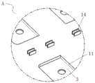
Fig. 1 is a schematic view showing a structure of a harness isolation board according to the present application in a downward direction.
Fig. 2 is a schematic view of another view of the harness isolation board of the present application.
Fig. 3 is an enlarged schematic view of the structure at a in fig. 1.
Fig. 4 is an enlarged schematic view of the structure at B in fig. 1.
Fig. 5 is a schematic structural diagram of the battery cell of the present application after being mounted on a beam isolation plate.
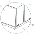
Fig. 6 is an enlarged schematic view of the structure at C in fig. 5.
Fig. 7 is a schematic view of the mounting structure of the cooling plate and the fireproof heat insulation pad of the present application.
Fig. 8 is a schematic structural view of the battery pack of the present application.
Fig. 9 is a schematic top view of a battery pack frame of the present application.
Fig. 10 is a schematic view of a partial cross-sectional structure at a via of the present application.
Fig. 11 is a schematic view of a partial cross-sectional structure at a through hole of the present application.
Marking:
1-a wire harness isolation plate, 10-an isolation plate body, 11-a first groove, 12-a second groove, 13-a pressure relief hole, 14-a clamping seat, 15-a limiting block and 16-a through hole;
2-an electric core; 3-bus bars; 4-a flexible circuit board; 5-a fireproof heat insulation pad;
6-frame side beams, 61-water channels and 62-mounting holes;
7, a frame bottom plate, 71-exhaust passages and 72-through holes;
8-cooling plate.
Detailed Description
In order that the above-recited objects, features and advantages of the present invention will be more clearly understood, a more particular description of the invention will be rendered by reference to the appended drawings and appended detailed description. In addition, embodiments of the present application and features of the embodiments may be combined with each other without conflict. In the following description, numerous specific details are set forth in order to provide a thorough understanding of the present invention, and the described embodiments are merely some, rather than all, embodiments of the present invention. All other embodiments, which can be made by those skilled in the art based on the embodiments of the present invention without making any inventive effort, are intended to fall within the scope of the present invention.
It should be noted that: unless defined otherwise, all technical and scientific terms used herein have the same meaning as commonly understood by one of ordinary skill in the art to which this invention belongs. The terminology used herein in the description of the invention is for the purpose of describing particular embodiments only and is not intended to be limiting of the invention. Like reference numerals and letters denote like items in the following figures, and thus once an item is defined in one figure, no further definition or explanation thereof is necessary in the following figures. Meanwhile, in the description of the present application, the terms "first", "second", and the like are used only to distinguish the description, and are not to be construed as indicating or implying relative importance.
As shown in fig. 1 to 11, in this embodiment, a wire harness isolation board 1 is provided, which includes an isolation board body 10, and when in installation and use, the isolation board body 10 can be used for carrying a battery cell 2, and an inverted installation arrangement of the battery cell 2 on the isolation board body 10 is realized.
As a preferable solution, the partition board body 10 is provided with a plurality of first grooves 11, and the first grooves 11 are embedded with the bus bars 3, and in the installation state, the positive electrode columns and the negative electrode columns of the electric core 2 are in contact with and electrically connected with the bus bars 3, so as to realize high-voltage electric connection of the electric core 2. Meanwhile, the battery cell 2 is arranged in a groove mode, and a certain pre-installation limiting effect can be achieved on the battery cell 2 after installation.
The first grooves 11 are arranged in rows along the length direction of the wire harness isolation board 1, as shown in fig. 1 and 2, in this embodiment, eight rows of the first grooves 11 are arranged and divided into four groups, so as to correspond to the inverted installation of the four groups of the battery cells 2.
Further, a plurality of second grooves 12 are further provided on the isolation board body 10, and a flexible circuit board 4 is installed in the second grooves 12, so that the electrical core 2 is connected with the low voltage through the flexible circuit board 4.
In this embodiment, as shown in fig. 2, the second grooves 12 are disposed between the two first grooves 11 in the same group, and the second grooves 12 are parallel to the first grooves 11 disposed in a row, so that the flexible circuit board 4 and the busbar 3 form a parallel structure in space, and the problems of spatial interference, contact short circuit, electromagnetic interference and the like caused by the mutual insertion of the flexible circuit board and the busbar in the conventional technology are avoided, so as to improve the safety of the whole battery system.
As a preferred solution, in this embodiment, the second groove 12 is preferably disposed on a side facing away from the battery cell 2, so as to avoid the thermal runaway from directly acting on the flexible circuit board 4 to further cause damage when the thermal runaway phenomenon occurs in the individual battery cells 2; meanwhile, the flexible circuit board 4 and the busbar 3 can have a certain height difference after being mounted.
As a preferred solution, in this embodiment, the outgoing ends of the busbar 3 and the flexible circuit board 4 are respectively disposed at two ends of the separator body 10, as shown in fig. 1, on the whole electrical circuit arrangement, the flexible circuit board 4 and the external low-voltage electrical connection terminal are disposed at one end, and the busbar 3 and the external high-voltage electrical connection terminal are disposed at the other end, so that the limited isolation of the high-voltage and low-voltage electrical directions during the electrical connection can be conveniently implemented, and the space utilization rate and the safety of the battery system are further improved.
In addition, a plurality of pressure relief holes 13 are further formed in the isolation plate body 10, and the setting positions of the pressure relief holes 13 correspond to the positions of the explosion-proof valves of the installed battery cells 2; in this embodiment, a plurality of the pressure relief holes 13 are arranged in a row and disposed between two first grooves 11 in the same group. In a preferred embodiment, an explosion-proof membrane is further disposed at the pressure relief hole 13, and the explosion pressure is less than or equal to 40kPa.
Further, in this embodiment, as shown in fig. 1 and 3, a plurality of card holders 14 are disposed on the partition board body 10, and a plurality of card holders 14 are arranged in a row and disposed between two adjacent groups of the first grooves 11, and at this time, the battery cells 2 are mounted on two sides of the card holders 14 in a row. The plurality of clamping seats 14 can facilitate the direct insertion type installation and arrangement of the subsequent fireproof heat insulation pad 5, and can improve the application safety of the battery cell 2.
Furthermore, in this embodiment, a plurality of limiting blocks 15 are further disposed on two side edges of the isolating plate body 10, and the distance between the two clamping bases 14 and the distance between the clamping bases 14 and the limiting blocks 15 are adapted to the length of the battery cell 2. Through the stopper 15 that sets up, can with cassette 14 mutually support, so that right the electric core 2 is spacing in the position after the installation, improves packaging efficiency.
In this embodiment, through the arranged harness isolation board 1, the integrated arrangement of the busbar 3 and the flexible circuit board 4 on the harness isolation board 1 can be realized, so that the integrated installation connection of high and low electric is realized, and the overall structure is simpler; meanwhile, the pressure relief holes 13 are further formed in the wire harness isolation plate 1, inverted installation of the battery cells 2 can be conveniently achieved, reserved space in the Z direction of the battery pack during design can be conveniently reduced, space utilization rate can be improved, and meanwhile thickness dimension after whole pack forming can be conveniently controlled.
In addition, as shown in fig. 5 to 11, a battery pack is further provided in this embodiment, which includes a plurality of the battery cells 2, a harness isolation board 1 as described above, and a battery pack frame including frame side rails 6 and a frame bottom plate 7.
The battery cell used in the embodiment is a battery cell in the conventional application at present, the positive pole, the negative pole and the explosion-proof valve of the battery cell 2 are all arranged at the top end of the battery cell 2, and the explosion-proof valve is arranged between the positive pole and the negative pole. When the battery pack is installed, the battery cells 2 are inversely installed on the wiring harness isolation plate 1, and the wiring harness isolation plate 1 is installed in the battery pack frame.
As a preferable mode, a cooling plate 8 is arranged between the two electric cores 2 along the width direction of the installed electric cores 2; in this embodiment, if four battery cells 2 are disposed in the length direction, the length of the cooling plate 8 is also adapted to the lengths of the four battery cells 2.
As a preferable solution, a fireproof heat insulation pad 5 is further interposed between the two electric cores 2 along the length direction of the installed electric core 2, and the provided fireproof heat insulation pad 5 may be used to block the thermal runaway phenomenon of the individual electric core 2 in the length direction of the electric core 2.
In this embodiment, a water inlet pipe and a water outlet pipe are respectively disposed at two sides of the bottom end of the cooling plate 8, a plurality of through holes 16 are disposed at two side edges of the isolation plate body 10, and the through holes 16 are arranged in a row, and the water inlet pipe and the water outlet pipe pass through the through holes 16 and extend from the other side surface of the harness isolation plate 1. Through the arranged through holes 16, the cooling plate 8 can be conveniently matched with the installation of the cooling plate 8, and the pre-installation and fixation of the cooling plate 8 are realized; and the cooling plate 8 can realize the cooling heat exchange of big side and big side laminating formula between the electric core 2, area of contact is bigger, and cooling heat exchange effect is better.
In addition, a water passage 61 is further provided in the frame side beam 6, and the water inlet pipe and the water outlet pipe are inserted into the frame side beam 6 and are communicated with the water passage 61. In practical application, the frame boundary beam 6 itself can have an inner cavity structure, and in this scheme, the right frame boundary beam 6's structure is reasonably utilized, so that the inner cavity structure therein is set up as the water channel 61, through with the cooling plate 8 cooperation installation is in order to form the return circuit that supplies the cooling liquid to circulate, realizes to the thermal management of electric core 2, and whole structure is simpler, also is convenient for control application cost simultaneously. As shown in fig. 10, in this embodiment, a plurality of mounting holes 62 corresponding to the through holes 16 are provided on the frame side beam 6, and the mounting holes 62 are communicated with the water channel 61, so as to form a circulation loop of the cooling liquid by plugging and mounting the cooling plate 8.
Further, in this embodiment, a plurality of exhaust ducts 71 and a plurality of through holes 72 communicating with the exhaust ducts 71 are provided in the frame bottom plate 7, as shown in fig. 11, the explosion-proof valves, the pressure release holes 13 and the through holes 72 are provided in a one-to-one correspondence and can be mutually communicated, so that after the explosion of the explosion-proof valves, explosion products can be discharged from the pressure release holes 13 and the through holes 72 into the exhaust ducts 71, so as to facilitate the final discharge of the explosion products.
In the embodiment, the inverted installation of the battery core 2 in the battery pack can be realized by applying the wire harness isolation plate 1 in the battery pack, so that the structure is novel; meanwhile, the problems of complex structure and unreasonable space occupation caused by arranging an electric connecting piece and an explosion-proof pressure relief system at the top of the battery cell module in the conventional technology when the battery cell 2 is arranged vertically can be avoided, so that the thickness of the whole battery pack can be set thinner, and the battery pack has better market prospect.
The foregoing is merely a specific embodiment of the present application and is not intended to limit the scope of the present application, and various modifications and variations can be made by those skilled in the art. Any modification, equivalent replacement, improvement, etc. made within the spirit and principles of the present application should be included in the protection scope of the present application. Variations and substitutions will be readily apparent to those skilled in the art within the scope of the present disclosure, and are intended to be included within the scope of the present disclosure. Therefore, the protection scope of the present application shall be subject to the protection scope of the claims.
It is noted that relational terms such as first and second, and the like are used solely to distinguish one entity or action from another entity or action without necessarily requiring or implying any actual such relationship or order between such entities or actions. Moreover, the terms "comprises," "comprising," or any other variation thereof, are intended to cover a non-exclusive inclusion, such that a process, method, article, or apparatus that comprises a list of elements does not include only those elements but may include other elements not expressly listed or inherent to such process, method, article, or apparatus. Without further limitation, an element defined by the phrase "comprising one … …" does not exclude the presence of other like elements in a process, method, article, or apparatus that comprises the element.
Claims (6)
1. The battery pack comprises a plurality of battery cells and is characterized by further comprising a wire harness isolation plate, a cooling plate and a frame side beam, wherein the wire harness isolation plate comprises an isolation plate body;
the positive pole, the negative pole and the explosion-proof valve of the battery cell are all arranged at the top end of the battery cell, and the battery cell is inversely arranged on the wire harness isolation plate;
the isolation board comprises a isolation board body, wherein the isolation board body is provided with a plurality of first grooves for installing bus bars and a plurality of second grooves for installing flexible circuit boards, the first grooves are arranged in a row, the second grooves are parallel to the first grooves arranged in a row, and the first grooves and the second grooves are respectively arranged on two side surfaces of the isolation board body;
the anti-explosion valve of the battery cell is provided with a plurality of pressure relief holes after corresponding installation on the isolation board body, a plurality of through holes are arranged on the edges of two sides of the isolation board body, and a plurality of through holes Kong Chenglie are arranged;
the cooling plates are clamped between the two electric cores along the width direction of the electric cores, water inlet pipes and water outlet pipes are respectively arranged at two sides of the bottom end of each cooling plate, and pass through the through holes;
the frame boundary beam is internally provided with a water passage, and the water inlet pipe and the water outlet pipe are inserted into the frame boundary beam and are communicated with the water passage.
2. The battery pack according to claim 1, wherein a bus bar is disposed in the first groove, a flexible circuit board is disposed in the second groove, and wire outlet ends of the bus bar and the flexible circuit board are located at both ends of the separator body, respectively.
3. The battery pack according to claim 1 or 2, wherein a plurality of clamping seats are arranged on the isolation plate body, the clamping seats are arranged in a row, the battery cells are arranged on two sides of the clamping seats in a row, and the distance between the two clamping seats is matched with the length of the battery cells.
4. The battery pack according to claim 3, wherein a plurality of limiting blocks are arranged on two side edges of the isolation plate body, and the distance between the clamping seat and the limiting blocks is matched with the length of the battery cell.
5. The battery pack according to claim 1, further comprising a frame base plate, wherein a plurality of exhaust channels and a plurality of through holes communicated with the exhaust channels are arranged in the frame base plate;
the explosion-proof valve, the pressure relief hole and the through hole are arranged in one-to-one correspondence and can be communicated with each other.
6. A battery pack according to claim 3, wherein a fireproof heat-insulating pad is interposed between the two cells along the length direction of the cells, and the fireproof heat-insulating pad is inserted on the holder.
Priority Applications (1)
| Application Number | Priority Date | Filing Date | Title |
|---|---|---|---|
| CN202310215925.7A CN115882155B (en) | 2023-03-08 | 2023-03-08 | Wire harness isolation plate and battery pack thereof |
Applications Claiming Priority (1)
| Application Number | Priority Date | Filing Date | Title |
|---|---|---|---|
| CN202310215925.7A CN115882155B (en) | 2023-03-08 | 2023-03-08 | Wire harness isolation plate and battery pack thereof |
Publications (2)
| Publication Number | Publication Date |
|---|---|
| CN115882155A CN115882155A (en) | 2023-03-31 |
| CN115882155B true CN115882155B (en) | 2023-05-26 |
Family
ID=85762050
Family Applications (1)
| Application Number | Title | Priority Date | Filing Date |
|---|---|---|---|
| CN202310215925.7A Active CN115882155B (en) | 2023-03-08 | 2023-03-08 | Wire harness isolation plate and battery pack thereof |
Country Status (1)
| Country | Link |
|---|---|
| CN (1) | CN115882155B (en) |
Citations (3)
| Publication number | Priority date | Publication date | Assignee | Title |
|---|---|---|---|---|
| DE102012217248A1 (en) * | 2012-09-25 | 2014-03-27 | Zf Friedrichshafen Ag | Arrangement for securing electric energy storage module in hybrid car, has cells and cooling elements that are connected together and secured to supporting frame for vehicle-mounted connection, via coolant distributor profiles |
| WO2022011513A1 (en) * | 2020-07-13 | 2022-01-20 | 威睿电动汽车技术(宁波)有限公司 | Battery module and vehicle |
| CN114335798A (en) * | 2021-12-23 | 2022-04-12 | 江苏汇智高端工程机械创新中心有限公司 | Battery box |
Family Cites Families (4)
| Publication number | Priority date | Publication date | Assignee | Title |
|---|---|---|---|---|
| CN210403889U (en) * | 2019-09-29 | 2020-04-24 | 蜂巢能源科技有限公司 | Battery cell connecting assembly, module and power battery pack |
| CN214797643U (en) * | 2021-05-31 | 2021-11-19 | 蜂巢能源科技有限公司 | Sampling assembly and battery module |
| CN115000575A (en) * | 2022-06-17 | 2022-09-02 | 广汽埃安新能源汽车有限公司 | Power battery liquid cooling device and electric vehicle |
| CN115498345A (en) * | 2022-09-09 | 2022-12-20 | 海南小鹏汽车科技有限公司 | Wiring harness isolation plate, battery pack and automobile |
-
2023
- 2023-03-08 CN CN202310215925.7A patent/CN115882155B/en active Active
Patent Citations (3)
| Publication number | Priority date | Publication date | Assignee | Title |
|---|---|---|---|---|
| DE102012217248A1 (en) * | 2012-09-25 | 2014-03-27 | Zf Friedrichshafen Ag | Arrangement for securing electric energy storage module in hybrid car, has cells and cooling elements that are connected together and secured to supporting frame for vehicle-mounted connection, via coolant distributor profiles |
| WO2022011513A1 (en) * | 2020-07-13 | 2022-01-20 | 威睿电动汽车技术(宁波)有限公司 | Battery module and vehicle |
| CN114335798A (en) * | 2021-12-23 | 2022-04-12 | 江苏汇智高端工程机械创新中心有限公司 | Battery box |
Also Published As
| Publication number | Publication date |
|---|---|
| CN115882155A (en) | 2023-03-31 |
Similar Documents
| Publication | Publication Date | Title |
|---|---|---|
| CN211480235U (en) | Battery pack | |
| CN108232363A (en) | The cold power battery module of liquid and automobile power cell packet | |
| CN113921995B (en) | Bus structure, serial-parallel connection module, battery pack, battery system and method | |
| CN104779355A (en) | Battery module including a heat exchanger in contact with the terminals of the module | |
| CN111952523A (en) | Battery pack | |
| CN109216621B (en) | Square cell module | |
| CN212659610U (en) | Battery module, battery package and vehicle | |
| CN216980676U (en) | Battery module, battery package and vehicle | |
| CN111952499A (en) | Battery module and automobile power battery | |
| CN115483475A (en) | Liquid cooling battery module | |
| CN115882155B (en) | Wire harness isolation plate and battery pack thereof | |
| CN219658795U (en) | Immersed liquid cooling battery pack | |
| CN211127600U (en) | Split power module | |
| CN220106743U (en) | Battery module | |
| CN116031567A (en) | Wire harness isolation plate, battery module, exhaust system and battery pack | |
| CN115472956A (en) | Cooling structure suitable for formula of lying electricity core and battery package thereof | |
| CN214099763U (en) | Battery module | |
| CN114388968A (en) | Non-module battery pack integration device adopting soft package battery core | |
| CN219917529U (en) | Combined structure of rectangular battery cell | |
| CN219086214U (en) | Wire harness isolation plate, battery pack frame and battery pack | |
| CN218333984U (en) | Cooling structure suitable for formula of lying electricity core and battery package thereof | |
| CN219419211U (en) | Liquid cooling plate and battery module | |
| CN218242067U (en) | Battery module | |
| CN219498073U (en) | Battery cell module structure and battery system | |
| CN217062327U (en) | Battery pack |
Legal Events
| Date | Code | Title | Description |
|---|---|---|---|
| PB01 | Publication | ||
| PB01 | Publication | ||
| SE01 | Entry into force of request for substantive examination | ||
| SE01 | Entry into force of request for substantive examination | ||
| GR01 | Patent grant | ||
| GR01 | Patent grant |