CN115822489B - Drilling tool and drilling coring method - Google Patents
Drilling tool and drilling coring method Download PDFInfo
- Publication number
- CN115822489B CN115822489B CN202310125881.9A CN202310125881A CN115822489B CN 115822489 B CN115822489 B CN 115822489B CN 202310125881 A CN202310125881 A CN 202310125881A CN 115822489 B CN115822489 B CN 115822489B
- Authority
- CN
- China
- Prior art keywords
- hollow shaft
- inner tube
- channel
- drilling tool
- central
- Prior art date
- Legal status (The legal status is an assumption and is not a legal conclusion. Google has not performed a legal analysis and makes no representation as to the accuracy of the status listed.)
- Active
Links
Images


Landscapes
- Earth Drilling (AREA)
Abstract
The embodiment of the application relates to the technical field of drilling of soil layers or rocks, in particular to a drilling tool and a drilling coring method. The drilling tool comprises an outer pipe, an inner pipe, a driving joint, a single-acting mechanism and a water isolation piece. An annular channel is formed between the inner tube and the outer tube. The driving joint is used for being connected with the drill rod so that the drill rod drives the outer tube to rotate, a central channel and a lateral flow channel are formed in the driving joint, and flushing liquid entering the central channel can enter the annular channel through the lateral flow channel. The single-acting mechanism is connected between the drive joint and the inner tube to enable the outer tube to rotate relative to the inner tube. The single-acting mechanism comprises a hollow shaft, and the hollow shaft is communicated with the central channel and the inner tube. The water barrier is configured to be operably disposed within the central passage when the coring operation is performed to isolate the lateral flow passage such that flushing fluid entering the central passage is able to enter the inner tube entirely through the water barrier, thereby creating hydraulic pressure to push a rock sample in the inner tube out of the bottom. The drilling tool can improve the core withdrawing operation efficiency.
Description
Technical Field
The invention relates to the technical field of drilling of soil layers or rocks, in particular to a drilling tool and a drilling coring method.
Background
The main structural components of the single-action double-tube drilling tool comprise a driving joint, an inner tube, an outer tube, a single-action mechanism and the like, when drilling is carried out, the outer tube rotates the inner tube without rotating, so that the mechanical disturbance of the drilling tool to a core (sample) can be effectively reduced, the long-time hole bottom dry drilling and core clamping operation is avoided, the matched bottom spraying or advanced double-tube drilling tool can effectively reduce the scouring of flushing fluid water flow to the core (sample), the core taking quality and core taking efficiency are greatly improved, and the single-action double-tube drilling tool is particularly suitable for core taking drilling of complex stratum.
However, when the rock sample is taken out from the single-action double-tube drilling tool, the single-action mechanism and the inner tube and the outer tube of the drilling tool are frequently required to be disassembled, then the assembly is carried out, the operation is complex, the core withdrawing efficiency is affected, and the auxiliary operation time is long.
Disclosure of Invention
Aiming at the technical problems, the embodiment of the application provides a drilling tool and a drilling and coring method capable of coring without disassembling a single-acting mechanism and an inner pipe and an outer pipe.
According to a first aspect of the present application, there is provided a drilling tool comprising: the bottom of the outer tube is connected with a drill bit; the inner tube is arranged on the radial inner side of the outer tube, and an annular channel is formed between the inner tube and the outer tube; the driving joint is connected to the top end of the outer tube and is used for being connected with the drill rod to drive the outer tube to rotate by the drill rod, a central channel and a plurality of lateral flow channels which are communicated with the central channel and the annular channel are formed in the driving joint, and flushing fluid entering the central channel can enter the annular channel through the lateral flow channels; the single-acting mechanism is connected between the driving joint and the inner tube so that the outer tube can rotate relative to the inner tube, and comprises a hollow shaft, wherein the hollow shaft is communicated with the central channel and the inner tube; and a water barrier configured to be operably disposed within the central passage upon a coring operation of the inner tube to break a path between the central passage and the plurality of lateral flow passages and maintain communication between the central passage and the hollow shaft such that flushing fluid entering the central passage is able to enter the inner tube entirely through the water barrier to create hydraulic pressure to push a rock sample in the inner tube out of the bottom.
According to a second aspect of the present application, there is provided a method of drilling and coring using the drilling tool of the first aspect of the present application, the method comprising a drilling and coring operation and a coring operation, wherein the coring operation comprises: lifting the drilling tool to the ground, removing the drill bit, and taking out the plugging piece from the central channel; placing a spacer in the central passage to break the path between the central passage and the plurality of lateral flow passages and maintain communication between the central passage and the hollow shaft; the central passage is provided with a flushing fluid, which is let into the inner tube via the spacer to push the rock sample in the inner tube out of the bottom of the inner tube.
According to the drilling tool, under the condition that the single-acting mechanism and the inner pipe and the outer pipe are not dismounted, the rock sample is directly pushed out of the inner pipe through hydraulic power, so that the core withdrawing operation efficiency is improved, the auxiliary time is shortened, and the overall efficiency of drilling operation is improved.
Drawings
Other objects and advantages of the present invention will become apparent from the following description of the invention with reference to the accompanying drawings, which provide a thorough understanding of the present invention.
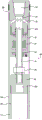
FIGS. 1a and 1b show schematic cross-sectional views of an upper and lower part, respectively, of a drilling tool according to an embodiment of the present invention;
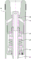
FIG. 2 shows a schematic partial cross-section of a drilling tool according to an embodiment of the present invention;
FIG. 3 shows a schematic partial cross-sectional view of a drilling tool in a coring operation in accordance with an embodiment of the present invention;
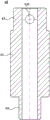
FIG. 4 shows a schematic cross-sectional view of a spacer according to an embodiment of the invention;
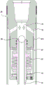
fig. 5 shows a schematic partial cross-section of a drilling tool in a drilling operation according to an embodiment of the invention.
It should be noted that the drawings are not necessarily to scale, but are merely shown in a schematic manner that does not affect the reader's understanding.
Reference numerals illustrate:
10. an outer tube; 11. an annular channel; 12. a centralizer; 13. a reamer; 14. a drill bit;
20. an inner tube; 21. a clamping spring seat; 22. clamping springs;
30. a drive joint; 31. a central passage; 32. a lateral flow channel; 33. a connecting threaded hole;
40. a single-acting mechanism; 41. a hollow shaft; 411. a top end face; 42. an inner pipe joint; 421. a connection channel; 43. a bearing seat; 431. an annular gap; 44. a bearing; 45. a spring; 46. a nut;
50. a blocking member;
60. a water barrier; 61. a main body pipe section; 62. a bottom pipe section; 63. a top pipe section; 631. and grabbing the hole.
Detailed Description
In order to make the objects, technical solutions and advantages of the present invention more apparent, the technical solutions of the present invention will be clearly and completely described below with reference to the accompanying drawings of the embodiments of the present invention. It will be apparent that the described embodiments are one embodiment, but not all embodiments, of the present invention. All other embodiments, which can be made by a person skilled in the art without creative efforts, based on the described embodiments of the present invention fall within the protection scope of the present invention.
It is to be noted that unless otherwise defined, technical or scientific terms used herein should be taken in a general sense as understood by one of ordinary skill in the art to which the present invention belongs.
In the description of the embodiments of the present invention, the meaning of "plurality" is at least two, for example, two, three, etc., unless explicitly defined otherwise.
Referring to fig. 1a, 1b and 2, a drilling tool according to an embodiment of the present invention includes: an outer tube 10, an inner tube 20, a drive joint 30 and a single action mechanism 40. The bottom of the outer tube 10 is connected with a drill bit 14. The inner tube 20 is disposed radially inward of the outer tube 10, and an annular passage 11 is formed between the inner tube 20 and the outer tube 10.
A drive joint 30 is connected to the top end of the outer tube 10 for connection with a drill rod for rotation of the outer tube 10 by the drill rod. The drive joint 30 is internally formed with a central passage 31 and a plurality of lateral flow passages 32 that communicate the central passage 31 with the annular passage 11, and the rinse liquid that has entered the central passage 31 can enter the annular passage 11 via the plurality of lateral flow passages 32.
A single-acting mechanism 40 is connected between the drive joint 30 and the inner tube 20 to enable rotation of the outer tube 10 relative to the inner tube 20. The single-acting mechanism 40 includes a hollow shaft 41, and the hollow shaft 41 communicates the central passage 31 with the inner tube 20.
Referring to fig. 3, the drilling tool of the present embodiment further includes a spacer 60 configured to be operatively disposed within the central passage 31 upon a coring operation of the inner tube 20 to break the passage between the central passage 31 and the plurality of lateral flow passages 32 and maintain communication between the central passage 31 and the hollow shaft 41 so that flushing fluid entering the central passage 31 can all enter the inner tube 20 via the spacer 60 to create hydraulic pressure to push out the rock sample in the inner tube 20 from the bottom.
In the center withdrawal operation, the drill is lifted to the ground, the drill bit 14 is removed, and the plugging member 50, which will be described later, is taken out from the center passage 31, so that the center flow passage inside the drill is completely penetrated from top to bottom (i.e., the connecting screw hole 33, the center passage 31, the hollow shaft 41, the connecting passage 421 and the inner tube 20 are in a communicating state); placing the spacer 60 in the central passage 31 to break the passage between the central passage 31 and the plurality of lateral flow passages 32 and maintain communication between the central passage 31 and the hollow shaft 41; the drive joint 30 is connected to the coring joint and the hydraulic pump to provide flushing fluid to the central passage 31, which is allowed to enter the inner tube 20 via the spacer 60 to push the rock sample in the inner tube 20 out of the bottom of the inner tube 20.
Therefore, the drilling tool provided by the embodiment of the application can directly push out the rock sample from the inner pipe 20 through hydraulic power under the condition that the single-acting mechanism 40 and the inner pipe and outer pipe are not dismounted, so that the core withdrawing operation efficiency is improved, the auxiliary time is shortened, and the overall efficiency of drilling operation is improved.
The outer diameter of the water barrier 60 and the central channel 31 may be in clearance fit, and the fit clearance may be 0.1-0.2 mm, so as to ensure smooth putting in or taking out of the water barrier 60 in the central channel 31 and ensure isolation of the lateral flow channels 32.
The spacer 60 may be a hollow tube. When the spacer 60 is placed in the central passage 31, the wall of the spacer 60 seals off the inlet of the lateral flow passage 32, forcing flushing liquid entering the central passage 31 along the hollow shaft 41 into the inner tube 20.
Referring to fig. 4, in some embodiments, the riser 60 may include a main body section 61 and a bottom section 62 that is connected to the bottom end of the main body section 61. Wherein the outer diameter of the body tube segment 61 is greater than the inner diameter of the hollow shaft 41 and less than the inner diameter of the central passage 31. The body tube segment 61 may be a clearance fit with the central passage 31. The outer diameter of the bottom tube section 62 is smaller than the inner diameter of the hollow shaft 41 to embed the hollow shaft 41. The bottom tube section 62 may be a clearance fit with the hollow shaft 41. The wall of the main body section 61 seals off the inlet of the lateral flow channel 32.
In some embodiments, the spacer 60 may further include a top tube section 63 connected to the top end of the main tube section 61, the top tube section 63 having an outer diameter smaller than the inner diameter of the central passage 31, and at least one gripping hole 631 provided on the circumference of the top tube section 63 to facilitate removal of the spacer 60 from the central passage 31. The number of the grip holes 631 may be one, two, three, or the like. In the illustrated embodiment, four gripping apertures 631 are provided in the peripheral wall of the top tube section 63. The gripping holes 631 may be hooked by a wire hook or the like to facilitate pulling out the spacer 60 from the center tunnel 31.
The drill rod is of a hollow structure, and a drill rod channel is formed in the drill rod. The drill rod, while driving the outer tube 10 in rotation, may also supply flushing liquid through the drill rod channel to the central channel 31. The top of the drive sub 30 forms a threaded connection hole 33 for cooperation with the drill rod. The connecting threaded bore 33 is connected to the central passage 31. The threaded connection hole 33 is generally tapered or cylindrical in configuration. The top pipe section 63 may be positioned within the connection threaded bore 33 to facilitate the removal and placement operations of the riser 60.
In some embodiments, during the coring operation, after the spacer 60 is placed in the central passage 31, the rock sample in the inner tube 20 may be hydraulically cored with a flushing fluid from a hydraulic pump.
In some embodiments, the drilling tool may further comprise: a coring bit (not shown) is configured to be removably coupled to the drive bit 30 during a coring operation of the inner tube 20, when the tool has been disconnected from the drill pipe and the tool is lifted to the surface. The outlet fitting is also adapted to be connected by piping to a hydraulic pump for supplying flushing fluid to the central passage 31. One end of the core-withdrawing joint can be in threaded connection with a connecting threaded hole 33 of the driving joint 30, and the other end of the core-withdrawing joint is connected with the hydraulic pump through a pipeline.
It will be readily appreciated that when cooling the drill bit 14 at the bottom of the hole by flushing fluid into the annular channel 11, it is necessary that the water pressure supplied from the surface is high due to the depth of the borehole. When the flushing liquid is used for core withdrawal, the flushing liquid is operated on the ground, so that a large water pressure is not needed. Thus, in some embodiments, the irrigant provides less pressure when the irrigant is used to coring than when the drill is drilling.
The drill bit 14 may be a diamond drill bit or other drill bit. In some embodiments, the length of the inner tube 20 may be 1.5-6 m, and the gap between the inner tube 20 and the outer tube 10 may be 1-10 mm. The lower part of the inner tube 20 is connected with a clamping spring seat 21 in a plugging manner, and a clamping spring 22 and a check ring are arranged in the clamping spring seat 21. In such an embodiment, when a coring operation is desired, the latch bearing 21 needs to be removed after lifting the drill to the ground and removing the drill bit 14, so that the rock sample can be smoothly pushed out from the bottom of the inner tube 20.
In some embodiments, the top end of the outer tube 10 can be connected with the driving joint 30 by adopting screw threads, the lower part of the outer tube 10 is provided with inner screw threads, a limiting step is arranged at a position 2-5 cm above the inner screw threads, a centralizer 12 is arranged at the limiting step, the lower part of the centralizer 12 is limited by means of the upper end face of a reamer 13, the reamer 13 is connected with the inner screw threads at the lower part of the outer tube 10, and the lower part of the reamer 13 is connected with a drill bit 14.
An annular gap 431 may exist between the single action mechanism 40 and the outer tube 10 such that rinse liquid entering the lateral flow channel 32 enters the annular channel 11 through the annular gap 431.
In some embodiments, the single action mechanism 40 may include: an inner tube fitting 42 is connected between the inner tube 20 and the hollow shaft 41. Inside the inner tube joint 42, a connection passage 421 is formed to communicate the hollow shaft 41 and the inner tube 20, and the connection passage 421 is concentric with the hollow shaft 41 and the inner tube 20.
The lower part of the hollow shaft 41 can be connected with the inner pipe joint 42 through screw threads, and a locking nut 46 and a gasket are arranged above the inner pipe joint 42. The connecting screw thread is rotated leftwards or rightwards along the hollow shaft 20, the gap between the bottom end of the clamping spring seat 21 at the lower part of the inner tube 20 and the step in the drill bit 14 can be adjusted, the gap adjustment range is 3-5 mm, and after the gap adjustment is proper, the locking nut 46 is screwed to lock the inner tube joint 42 to prevent loosening.
The single-action mechanism 40 may further include: bearing housing 43 and bearing 44. The bearing housing 43 is connected to the drive joint 30. The bearing 44 is arranged on the bearing seat 43, and the hollow shaft 41 extends downward via the radially inner side of the bearing 44 to be connected with the inner pipe joint 42. The bearing 44 may be a thrust bearing 44. The number of bearings 44 may be two, with a spring 45 disposed between the two bearings 44. The spring 45 may be a belleville spring with a spring preload gap of 0.5-3 mm.
In some embodiments, the single action mechanism 40 further includes a seal ring, gasket, or the like, disposed within the bearing housing 43. Specifically, a sealing ring, a gasket and a thrust bearing 44 are sequentially arranged between the hollow shaft 41 and the driving joint 30, and are arranged on the hollow shaft 41, and the upper part and the lower part are respectively limited by an inner hole step of the driving joint 30 and an outer step of the hollow shaft 41. The lower part of the outer step of the hollow shaft 41 is provided with a disc spring 45, a gasket and a thrust bearing 44 in sequence. The upper part of the bearing seat 43 is connected with the driving joint 30 by screw threads, and the thrust bearing 44, the belleville springs 45 and the gaskets are completely sealed. The hollow shaft 41 is penetrated by the bottom of the bearing seat 43. The bearing housing 43 is provided with a grease cup at the side or bottom for injecting grease into the bearing housing 43.
In some embodiments, the drive sub 30 may have three threads, an upper conical or cylindrical inner thread, disposed within the connection threaded bore 33 for connection to a drill pipe pin; the middle part is an outer screw thread for connecting the upper part of the outer tube 10; the lower part is an outer screw thread, the outer diameter is smaller than the inner diameter of the outer tube 10, and the bearing seat 43 of the single-acting mechanism 40 is connected. The plurality of lateral flow channels 32 are uniformly distributed along the circumference of the central channel 31. The lateral flow channel 32 is located between the middle outer screw thread and the lower outer screw thread, and communicates the central channel 31 with the annular channel 11 of the inner and outer pipes. In some embodiments, the radially outer surface of the drive joint 30 may also be provided with gauge alloy to prevent wear to the outer diameter.
Referring to fig. 5, in some embodiments, the drilling tool further comprises: a closure 50 is operably disposed within the central passage 31 to inhibit flushing liquid from the central passage 31 from entering the inner tube 20 via the hollow shaft 41 and to permit flushing liquid in the inner tube 20 to flow upwardly into the central passage 31. Wherein, when the inner tube 20 is subjected to the coring operation, the blocking member 50 is removed from the central passage 31, and then the water blocking member 60 is operatively disposed in the central passage 31.
In such an embodiment, by providing the blocking member 50, the hollow shaft 41 can be blocked by the blocking member 50 during the drilling operation, and then the drive sub 30 can be connected to the drill rod for coring. During the drilling and coring process, the blocking piece 50 seals the top end of the hollow shaft 41, so that the flushing liquid entering the central channel 31 can only flow into the lateral flow channel 32 and thus into the annular channel 11 between the inner tube 20 and the outer tube 10. During core drilling, a rock sample enters the inner tube 20 from the bottom of the inner tube 20, the volume space above the rock sample in the inner tube 20 is gradually reduced, liquid above the rock sample is discharged to the central channel 31 through the blocking piece 50, and the liquid and the upper flushing liquid are converged and enter the annular channel 11 between the inner tube 20 and the outer tube 10 through the lateral flow channel 32, so that the drilled rock sample is ensured to smoothly enter the inner tube 20.
It will be readily appreciated that in the coring operation, the closure 50 is removed from the central passage 31 prior to the placement of the spacer 60 into the central passage 31. That is, during the coring operation, the drill may be lifted to the ground, the drill may be set flat, the drill bit 14 may be removed, the end of the drill that is to be connected to the drill bit 14 may be lifted slightly upward, and then the closure member 50 may be removed from the central passage 31 by gravity, or the closure member 50 may be pulled out of the central passage 31 by a screwdriver, wire, or the like.
In some embodiments, the top end of the hollow shaft 41 is embedded within the central passage 31 of the drive joint 30. The outer diameter of the blocking piece 50 is larger than the inner diameter of the hollow shaft 41 and smaller than the inner diameter of the central passage 31, and the blocking piece 50 blocks the top end opening of the hollow shaft 41 when the blocking piece 50 is disposed in the central passage 31. By the arrangement, the plugging piece 50 can be positioned in the central channel 31 after entering the central channel 31, so that the plugging piece 50 is close to the top end opening of the connecting threaded hole 33, and the plugging piece 50 can be conveniently taken out and put in.
Specifically, the closure 50 may be rolled out under gravity as the closure 50 is removed; or the closure 50 may be removed by extending a tool (e.g., screwdriver, wire, etc.) directly into the central passage 31. Because the closure 50 is closer to the top end opening of the connecting threaded bore 33, it is easier to align and manipulate the closure 50 when manually removed with a tool.
In some embodiments, the closure 50 is a sphere. The sphere may be a metal sphere, such as a steel ball. In order to avoid that the ball deviates from the top end opening of the hollow shaft 41, so that the ball cannot block the top end opening of the hollow shaft 41, the top end face 411 of the hollow shaft 41 may be formed into an inner conical surface. Due to the presence of the inner conical surface, when the ball falls in the central passage 31, the ball can smoothly enter the conical surface, and the top end opening of the hollow shaft 41 is blocked. And, when taking out the sphere, the sphere will automatically roll off the hollow shaft 41 after the drill is put flat due to the existence of the inner conical surface. Because the plugging member 50 is close to the top end opening of the connecting threaded hole 33, the ball is convenient to take out manually.
The embodiment of the application also provides a drilling coring method, which uses the drilling tool of any embodiment of the application to drill and core. The borehole coring method may include a borehole coring operation and a coring operation. Wherein, the heart operation of moving back includes: lifting the drilling tool to the ground, horizontally placing the drilling tool, and detaching the drill bit 14; after the blocking member 50 is removed from the central passage 31, the water blocking member 60 is placed in the central passage 31 to break the passages between the central passage 31 and the plurality of lateral flow passages 32 and maintain communication between the central passage 31 and the hollow shaft 41; the central passage 31 is provided with a flushing fluid, which is forced into the inner tube 20 via the spacer 60 to push the rock sample in the inner tube 20 out of the bottom of the inner tube 20. After pushing the rock sample in the inner tube 20 out of the bottom of the inner tube 20, the spacer 60 may be removed from the central passage 31.
In some embodiments, the drive connection 30 may be connected to the withdrawal connection and hydraulic pump after placement of the spacer 60, allowing flushing fluid to enter the interior of the central passage 31 via the withdrawal connection.
In some embodiments, the borehole coring operation includes: when the drilling tool is put into the drilling hole, the central flow passage of the drilling tool is in a through state from top to bottom; when the drilling tool is connected with the drill rod and is lowered to the bottom of the hole, flushing fluid is provided to the central channel 31 by the drill rod channel, so that the flushing fluid enters the annular channel 11 through the plurality of lateral flow channels 32 and enters the inner tube 20 through the hollow shaft 41 to perform flushing operation on the hole; after the flushing operation is completed, the blocking piece 50 is put into the drill rod channel, and the blocking piece 50 reaches the central channel 31 under the action of gravity and flushing liquid force to block the hollow shaft 41, so that the flushing liquid can enter the annular channel 11 through the plurality of lateral flow channels 32 to flush the drill hole; and then, the drill rod is utilized to drive the drilling tool to rotate for drilling and coring.
It will be readily appreciated that if the closure member 50 is placed into the central passage 31 during a drilling coring operation, then during a coring operation, the closure member 50 needs to be removed from the central passage 31 prior to placing the spacer 60 into the central passage 31.
In some embodiments, the drive sub 30 is connected to the drill pipe, and flushing fluid is provided from the drill pipe passage to the central passage 31 after the drill has been lowered to the bottom of the hole.
In some embodiments, when the drilling tool is lowered to the bottom of the hole, the drill rod and the central flow passage of the drilling tool are completely penetrated from top to bottom before the plugging member 50 is not put into the hole, and flushing fluid can be provided to the central passage 31 in a large pump quantity to punch and remove sediment in the hole. After the punching operation is completed, the plug 50 can be inserted from the drill pipe channel. The closure member 50 is positioned in the central hole at the upper end of the hollow shaft 41 to form a one-way valve for isolating the flushing fluid from the upper portion of the inner tube 20 so that the flushing fluid can only enter the annular passage 11 between the inner and outer tubes from the lateral flow passage 32 of the drive joint 30.
In some embodiments, after the plug 50 is inserted through the drill pipe passage, the flushing fluid may be pumped into the drill pipe passage to send the plug 50 to the top of the hollow shaft 41. So that on the one hand the speed with which the closure member 50 reaches the top of the hollow shaft 41 can be increased and on the other hand the borehole can be flushed.
The drilling and coring method according to the embodiment of the present application is described below with reference to specific embodiments.
(1) Drilling coring operation: after the drilling tool is lowered to the bottom of the hole, punching holes with large pump quantity, then throwing the plugging piece 50 from the drill rod channel, and starting the pump to convey the plugging piece 50 to the top of the hollow shaft 41; after the normal drilling and coring are performed for a certain length, stopping the pump, pressurizing the drilling tool for 0.2-1.5 t, slowly rotating the drilling tool for 3-5 circles, and lifting the long drill rod drilling tool; the length of the drill coring does not exceed the receiving length of the inner tube 20.
(2) And (3) core withdrawing operation: after the drilling tool is lifted to the ground, the drill bit 14 and the clamping spring seat 21 are removed, the plugging piece 50 is taken out, the water blocking piece 60 is plugged into the central channel 31 from the driving joint 30 or the wire changing joint (namely, the joint connecting the drill rod joint and the driving joint 30) to be above the hollow shaft 41, the core withdrawing joint is in threaded connection with the driving joint 30, the core withdrawing joint is connected with the slurry pump by utilizing a high-pressure rubber tube, flushing fluid enters the upper part of the inner tube 20 from the driving joint 30 through the hollow shaft 41, and a rock sample is pushed out from the bottom. After the core is removed, the water-proof piece 60 is taken out, the clamp spring seat 21 and the drill bit 14 are installed, and the next drilling core-taking operation is performed.
It should also be noted that, in the embodiments of the present invention, the features of the embodiments of the present invention and the features of the embodiments of the present invention may be combined with each other to obtain new embodiments without conflict.
The present invention is not limited to the above embodiments, but the scope of the invention is defined by the claims.
Claims (8)
1. A drilling tool, comprising:
the bottom of the outer tube is connected with a drill bit;
the inner tube is arranged on the radial inner side of the outer tube, and an annular channel is formed between the inner tube and the outer tube;
the driving joint is connected to the top end of the outer tube and is used for being connected with a drill rod to drive the outer tube to rotate, a central channel and a plurality of lateral flow channels which are communicated with the central channel and the annular channel are formed in the driving joint, and flushing fluid entering the central channel can enter the annular channel through the lateral flow channels;
the single-acting mechanism is connected between the driving joint and the inner tube so that the outer tube can rotate relative to the inner tube, and comprises a hollow shaft, wherein the hollow shaft is communicated with the central channel and the inner tube; and
a spacer configured to be operably disposed within the central passage upon a coring operation of the inner tube to break the passageway between the central passage and the plurality of lateral flow passages and maintain communication between the central passage and the hollow shaft so that flushing fluid entering the central passage can all enter the inner tube via the spacer to create hydraulic pressure to push out the rock sample in the inner tube from the bottom;
when the water-proof piece is put into the central channel, the pipe wall of the water-proof piece seals the inlet of the lateral flow channel, and flushing fluid entering the central channel is forced to enter the inner pipe along the hollow shaft; the drilling tool further comprises: a center withdrawal coupling configured to be detachably connected to the drive coupling upon a center withdrawal operation of the inner tube, the center withdrawal coupling further configured to be connected to a hydraulic pump to provide flushing fluid to the center passage;
the drilling tool further comprises: a blocking member operably disposed within the central passage to inhibit flushing fluid from the central passage from entering the inner tube via the hollow shaft and to permit flushing fluid in the inner tube to flow upwardly into the central passage,
when the inner tube is subjected to the core withdrawing operation, the blocking piece is removed from the central channel, and then the water-proof piece is operably arranged in the central channel.
2. The drilling tool as recited in claim 1, wherein the spacer comprises a main body section and a bottom section connected to a bottom end of the main body section, wherein an outer diameter of the main body section is greater than an inner diameter of the hollow shaft and less than an inner diameter of the central passage, and an outer diameter of the bottom section is less than an inner diameter of the hollow shaft to embed the hollow shaft.
3. The drilling tool as recited in claim 2, wherein the spacer further comprises a top tube section connected to the top end of the main tube section, the top tube section having an outer diameter less than the inner diameter of the central passage, at least one gripping aperture being provided on a circumference of the top tube section to facilitate removal of the spacer from the central passage.
4. The drilling tool as recited in claim 1, wherein the top end of the hollow shaft is embedded in a central passage of the drive joint, the plug having an outer diameter greater than an inner diameter of the hollow shaft and less than an inner diameter of the central passage,
when the plugging piece is arranged in the central channel, the plugging piece plugs the top end opening of the hollow shaft.
5. The drilling tool as recited in claim 4, wherein the plug is a sphere and the top end surface of the hollow shaft forms an internal conical surface.
6. The drilling tool as recited in claim 1, wherein the single action mechanism further comprises:
the inner pipe joint is connected between the inner pipe and the hollow shaft, a connecting channel which is communicated with the hollow shaft and the inner pipe is formed in the inner pipe joint, and the connecting channel is concentric with the hollow shaft and the inner pipe.
7. A method of borehole coring using the drilling tool of any one of claims 1-6, the method comprising a borehole coring operation and a coring operation, wherein the coring operation comprises:
lifting the drilling tool to the ground, removing the drill bit, and taking out the plugging piece from the central channel;
placing the spacer into the central channel to break the pathway between the central channel and the plurality of lateral flow channels and maintain communication between the central channel and the hollow shaft;
providing a flushing fluid to the central passage, causing the flushing fluid to enter the inner tube via the spacer to create hydraulic pressure to push the rock sample in the inner tube out of the bottom of the inner tube.
8. The method of claim 7, wherein the borehole coring operation comprises:
connecting the drilling tool with a drill rod to lower the drilling tool to the bottom of a hole, providing flushing fluid to the central channel through a drill rod channel of the drill rod, enabling the flushing fluid to enter the annular channel through the lateral flow channels, and enabling the flushing fluid to enter the inner pipe through the hollow shaft to perform flushing operation on the drill hole;
after the flushing operation is finished, placing a blocking piece into the drill rod channel, enabling the blocking piece to reach the central channel under the action of gravity and flushing liquid water power so as to block the hollow shaft, and enabling the flushing liquid to enter the annular channel through the lateral flow channels to flush a drill hole; and
and driving the drilling tool to drill and core by using the drill rod.
Priority Applications (1)
| Application Number | Priority Date | Filing Date | Title |
|---|---|---|---|
| CN202310125881.9A CN115822489B (en) | 2023-02-15 | 2023-02-15 | Drilling tool and drilling coring method |
Applications Claiming Priority (1)
| Application Number | Priority Date | Filing Date | Title |
|---|---|---|---|
| CN202310125881.9A CN115822489B (en) | 2023-02-15 | 2023-02-15 | Drilling tool and drilling coring method |
Publications (2)
| Publication Number | Publication Date |
|---|---|
| CN115822489A CN115822489A (en) | 2023-03-21 |
| CN115822489B true CN115822489B (en) | 2023-05-09 |
Family
ID=85521693
Family Applications (1)
| Application Number | Title | Priority Date | Filing Date |
|---|---|---|---|
| CN202310125881.9A Active CN115822489B (en) | 2023-02-15 | 2023-02-15 | Drilling tool and drilling coring method |
Country Status (1)
| Country | Link |
|---|---|
| CN (1) | CN115822489B (en) |
Family Cites Families (5)
| Publication number | Priority date | Publication date | Assignee | Title |
|---|---|---|---|---|
| US6216804B1 (en) * | 1998-07-29 | 2001-04-17 | James T. Aumann | Apparatus for recovering core samples under pressure |
| CN106507861B (en) * | 2007-08-15 | 2012-08-15 | 核工业二一六大队 | Two-tube single action core drill |
| CN102797427A (en) * | 2012-08-27 | 2012-11-28 | 中国地质科学院勘探技术研究所 | Rock core ejection method |
| CN106837230B (en) * | 2017-02-17 | 2019-04-05 | 常州工学院 | A kind of double movable double-tube list drill bit core drill and its application method |
| CN113898286B (en) * | 2021-09-13 | 2024-01-05 | 中铁第四勘察设计院集团有限公司 | Single-action drilling tool and composite coring drilling tool |
-
2023
- 2023-02-15 CN CN202310125881.9A patent/CN115822489B/en active Active
Also Published As
| Publication number | Publication date |
|---|---|
| CN115822489A (en) | 2023-03-21 |
Similar Documents
| Publication | Publication Date | Title |
|---|---|---|
| US6595288B2 (en) | Method and multi-purpose apparatus for dispensing and circulating fluid in wellbore casing | |
| US4271916A (en) | System for adapting top head drilling rigs for reverse circulation drilling | |
| US5918673A (en) | Method and multi-purpose apparatus for dispensing and circulating fluid in wellbore casing | |
| CN109025876B (en) | Rope salvaging type hydraulic forced coring drilling tool | |
| NO300654B1 (en) | System for ring cementing and leaching of wells | |
| CN102678040A (en) | Drilling device and method for baseplate in coal mine roadway | |
| US8955604B2 (en) | Receptacle sub | |
| US2708103A (en) | Combination drill and core bit | |
| MXPA01003767A (en) | Drilling method. | |
| CN111206876A (en) | Top drive gas reverse circulation drilling ground equipment system | |
| CN115822489B (en) | Drilling tool and drilling coring method | |
| CN201567988U (en) | Automatic grouting circulation device for casing running | |
| CN104481451A (en) | Top driving well cementing casing head | |
| US11549324B2 (en) | Pumping stinger overshot | |
| CN112360389A (en) | Small workover operation method for casing leakage plugging | |
| CN112482985A (en) | Drilling equipment is pressed in area of oil gas well head | |
| EP4013939A1 (en) | Downhole apparatus and methods for casing | |
| CN116006108B (en) | Drilling tool and drilling coring method | |
| US2082010A (en) | Rotary swivel for removable wire line drills | |
| CN218787108U (en) | Downhole drill clamping rod taking-out device | |
| CN213627502U (en) | Prevent stifled anti-overflow drilling mud tubular column | |
| CN213510521U (en) | Screw rod drilling tool anti-blocking tool | |
| AU2013201651A1 (en) | Pressure feed system for a down hole drill | |
| CN211038597U (en) | Carbonate rock oil well screen pipe well completion pipe string with power guide shoe | |
| CN211950337U (en) | Impact rotary jet drilling tool |
Legal Events
| Date | Code | Title | Description |
|---|---|---|---|
| PB01 | Publication | ||
| PB01 | Publication | ||
| SE01 | Entry into force of request for substantive examination | ||
| SE01 | Entry into force of request for substantive examination | ||
| GR01 | Patent grant | ||
| GR01 | Patent grant |