CN115804980B - Self-cleaning filter for ship ballast water treatment system - Google Patents
Self-cleaning filter for ship ballast water treatment system Download PDFInfo
- Publication number
- CN115804980B CN115804980B CN202310083383.2A CN202310083383A CN115804980B CN 115804980 B CN115804980 B CN 115804980B CN 202310083383 A CN202310083383 A CN 202310083383A CN 115804980 B CN115804980 B CN 115804980B
- Authority
- CN
- China
- Prior art keywords
- filter
- cavity
- frame
- fixedly connected
- cleaning
- Prior art date
- Legal status (The legal status is an assumption and is not a legal conclusion. Google has not performed a legal analysis and makes no representation as to the accuracy of the status listed.)
- Active
Links
Images



Landscapes
- Filtration Of Liquid (AREA)
Abstract
Description
技术领域technical field
本发明涉及船舶压载水技术领域,尤其涉及一种船舶压载水处理系统用自清过滤器。The invention relates to the technical field of ship ballast water, in particular to a self-cleaning filter for a ship ballast water treatment system.
背景技术Background technique
船舶压载水过滤器是对海水进行过滤清理用的一种过滤装置,在海洋航行的船只上均有设置,其主要作用是船只在装载海水时将海水中细小的微生物、细菌、漂浮物等过滤出来,防止压载水在其它地点排放时使当地环境受到污染,生态系统遭到破坏。The ship's ballast water filter is a filter device for filtering and cleaning seawater. It is installed on ships sailing in the ocean. Its main function is to remove small microorganisms, bacteria, floating objects, etc. in the seawater when the ship is loading seawater. Filter out to prevent the ballast water from polluting the local environment and destroying the ecosystem when it is discharged in other places.
现有船舶压载水过滤器工作时,将海水导入过滤器中,通过设置在内壁上的过滤筒对海水进行过滤,再通过泵的抽取将净水运输到压载水腔内,传统过滤筒过滤面积有限,所需清理间隔短次数频繁,并且因为杂质会在过滤器内任意地方包括抽污管上附着,会产生清理死角,影响过滤器内部的环境。When the existing ship ballast water filter is working, the seawater is introduced into the filter, and the seawater is filtered through the filter cartridge arranged on the inner wall, and then the purified water is transported into the ballast water cavity by pumping. The traditional filter cartridge The filter area is limited, the required cleaning interval is short and the frequency is frequent, and because impurities will adhere to any place in the filter, including the sewage pipe, there will be a cleaning dead angle, which will affect the environment inside the filter.
发明内容Contents of the invention
为了克服上述技术背景中提出的技术问题,本发明提供了一种高效过滤自清理的船舶压载水处理系统用自清过滤器。In order to overcome the technical problems raised in the above technical background, the present invention provides a self-cleaning filter for high-efficiency filtering and self-cleaning ship ballast water treatment system.
本发明的技术实施方案为:一种船舶压载水处理系统用自清过滤器,包括有过滤壳体,过滤壳体上端固定连接有盖体,盖体上设有进水管,过滤壳体下部设有净水管,过滤壳体底部固定连通有排污管,过滤壳体底部固定连接有支撑架,其特征是:还包括有过滤组件,用于过滤压载水的过滤组件设置于过滤壳体内部,过滤壳体贯穿设置有用于清理过滤组件的清理部件,清理部件将过滤壳体内部腔体分隔为待过滤腔和排污腔,过滤组件由环形过滤框、连通框和过滤筒组成,过滤壳体内设置有由外到内直径逐渐变小的环形过滤框,最外层环形过滤框与过滤壳体内壁固定连接,其中环形过滤框内设有环形过滤腔,过滤壳体中心轴线设有过滤筒,过滤筒内设有筒形过滤腔,相邻的环形过滤框之间通过对称固接的连通框将环形过滤腔连通,过滤筒通过连通框与相邻的环形过滤框相固定且连通,其中过滤筒内的筒形过滤腔通过连通框与最内层环形过滤框内的环形过滤腔连通,最外层环形过滤框下部设置有过滤腔通孔,最外层环形过滤框与过滤壳体通过过滤腔通孔与净水管连通。The technical embodiment of the present invention is: a self-cleaning filter for ship ballast water treatment system, including a filter housing, the upper end of the filter housing is fixedly connected with a cover, the cover is provided with a water inlet pipe, and the lower part of the filter housing is There is a water purification pipe, the bottom of the filter housing is fixedly connected with a sewage pipe, and the bottom of the filter housing is fixedly connected with a support frame. It is characterized in that: it also includes a filter assembly, and the filter assembly for filtering ballast water is arranged in the filter housing Inside, the filter shell is provided with a cleaning part for cleaning the filter assembly. The cleaning part divides the inner cavity of the filter shell into a chamber to be filtered and a sewage discharge chamber. The filter assembly is composed of an annular filter frame, a connecting frame and a filter cartridge. The filter shell The body is provided with an annular filter frame whose diameter gradually decreases from outside to inside, and the outermost ring filter frame is fixedly connected with the inner wall of the filter housing, wherein an annular filter cavity is arranged inside the ring filter frame, and a filter cartridge is arranged on the central axis of the filter housing , the filter cartridge is provided with a cylindrical filter chamber, and the adjacent annular filter frames are connected to each other through a symmetrically fixed communication frame, and the filter cartridge is fixed and communicated with the adjacent annular filter frames through the communication frame, wherein The cylindrical filter cavity in the filter cartridge communicates with the annular filter cavity in the innermost annular filter frame through the connecting frame, the lower part of the outermost annular filter frame is provided with a filter cavity through hole, and the outermost annular filter frame and the filter housing pass through The through hole of the filter cavity is communicated with the water purification pipe.
更为优选的是,过滤壳体与盖体侧部分别设置有视窗,视窗用于观察过滤组件和污水腔内杂质附着情况。More preferably, the side parts of the filter housing and the cover are respectively provided with viewing windows, and the viewing windows are used to observe the attachment of impurities in the filter assembly and the sewage chamber.
更为优选的是,连通框的水平截面设置为扇面结构,连通框与相邻环形过滤框形成扇面形过滤通道,用于减少清理死角。More preferably, the horizontal section of the connecting frame is set as a fan structure, and the connecting frame and the adjacent ring-shaped filter frame form a fan-shaped filtering channel, which is used to reduce cleaning dead ends.
更为优选的是,每个连通框水平截面均为内小外大,且相邻的连通框水平截面内小外大,用于由内而外增加流通量。More preferably, the horizontal section of each connecting frame is small on the inside and large on the outside, and the horizontal section of adjacent connecting frames is small on the inside and large on the outside, so as to increase the flow rate from inside to outside.
更为优选的是,用于对环形过滤框和过滤筒的杂质进行清理的清理部件包括有往复电机,往复电机固定安装于支撑架,往复电机输出端固定连接有与过滤壳体转动配合的第一传动轴,第一传动轴上部为中空结构,且其中空部位侧壁周向开口,第一传动轴上端固定连接有与过滤壳体转动配合的隔板,隔板内设置有汇水腔,隔板上固定连接有均匀间隔分布的清理管,清理管分布在过滤组件内部的缝隙中,清理管对称贯穿设置有T形滑槽,汇水腔通过清理管与待过滤腔相连通,汇水腔通过第一传动轴上部与排污腔相连通,清理管远离隔板的一端固接有固定杆,固定杆内设置有用于传动的空腔,与固定杆的空腔相邻的清理管穿入其内,固定杆底面位于环形过滤框、连通框和过滤筒的上侧。More preferably, the cleaning component for cleaning the impurities in the annular filter frame and the filter cartridge includes a reciprocating motor, the reciprocating motor is fixedly mounted on the support frame, and the output end of the reciprocating motor is fixedly connected with a first filter that is rotatably matched with the filter housing. A transmission shaft, the upper part of the first transmission shaft is a hollow structure, and the side wall of the hollow part is opened in the circumferential direction, the upper end of the first transmission shaft is fixedly connected with a partition that is rotatably matched with the filter housing, and a water collection chamber is arranged inside the partition. The separator is fixedly connected with evenly spaced cleaning pipes, and the cleaning pipes are distributed in the gaps inside the filter assembly. The cleaning pipes are symmetrically penetrated with T-shaped chutes, and the water collection chamber is connected with the chamber to be filtered through the cleaning pipes. The chamber is connected with the sewage chamber through the upper part of the first transmission shaft. The end of the cleaning pipe away from the partition is fixedly connected with a fixed rod. A cavity for transmission is arranged in the fixed rod, and the cleaning pipe adjacent to the cavity of the fixed rod penetrates into the Inside, the bottom surface of the fixing rod is located on the upper side of the annular filter frame, the communication frame and the filter cartridge.
更为优选的是,隔板于清理管贯穿处周围设置有吸污孔,吸污孔连通汇水腔与环形过滤框和过滤筒形成的缝隙。More preferably, the separator is provided with a sewage suction hole around the penetration of the cleaning pipe, and the sewage suction hole communicates with the gap formed by the water collection cavity, the annular filter frame and the filter cylinder.
更为优选的是,还包括有预处理部件,预处理部件贯穿设置于过滤壳体,预处理部件用于对环形过滤框和过滤筒上过厚的附着杂质进行清理,预处理部件包括有转向电机,转向电机固定安装于支撑架,转向电机输出端固定安装有输出齿轮,第一传动轴外转动设置有贯穿并与过滤壳体转动配合的传动套筒,传动套筒一端固定连接有与输出齿轮啮合传动的第一外齿环,传动套筒上位于第一外齿环上侧固接有密封壳体,传动套筒上部设置有第二外齿环,且第二外齿环位于密封壳体内部,密封壳体上端固接有与隔板固定连接的固定套筒,密封壳体内部对称设置有第二传动轴,第二传动轴穿过固定套筒与隔板转动连接,第二传动轴固接有与第二外齿环啮合传动的传动齿轮,第二传动轴远离传动齿轮的一端通过皮带传动件与隔板传动连接另一端转动连接在固定杆的螺旋形刮板上,螺旋形刮板内侧紧贴清理管,螺旋形刮板外部紧贴环形过滤框和过滤筒的外壁。More preferably, it also includes a pretreatment component, the pretreatment component is arranged through the filter housing, and the pretreatment component is used to clean up the excessively thick adhered impurities on the annular filter frame and the filter cartridge, and the pretreatment component includes a steering The motor, the steering motor is fixedly installed on the support frame, the output end of the steering motor is fixedly installed with an output gear, the first transmission shaft is rotated outside and is provided with a transmission sleeve that penetrates and rotates with the filter housing, and one end of the transmission sleeve is fixedly connected with the output The first external gear ring for gear meshing transmission, the transmission sleeve is fixedly connected with the sealing shell on the upper side of the first external gear ring, the upper part of the transmission sleeve is provided with the second external gear ring, and the second external gear ring is located in the sealing shell Inside the body, the upper end of the sealed casing is fixedly connected with a fixed sleeve fixedly connected with the partition, and the inside of the sealed casing is symmetrically provided with a second transmission shaft, which passes through the fixed sleeve and is rotatably connected with the partition. The shaft is fixedly connected with a transmission gear meshing with the second external gear ring. One end of the second transmission shaft away from the transmission gear is connected to the partition through a belt drive and the other end is rotatably connected to the spiral scraper of the fixed rod. The inside of the scraper is close to the cleaning pipe, and the outside of the spiral scraper is close to the ring-shaped filter frame and the outer wall of the filter cartridge.
更为优选的是,还包括有用于将待过滤腔和排污腔侧壁杂质进行刮除的刮除组件,刮除组件包括有内齿环,内齿环与传动齿轮传动配合,污水腔刮板与内齿环通过异形连接件固定连接,异形连接件贯穿密封壳体,异形连接件与密封壳体和密封板转动连接,污水腔刮板通过固定连杆贯穿密封壳体,污水腔刮板与密封壳体和密封板转动连接,污水腔刮板远离传动齿轮的一端紧贴排污腔侧壁,T形固定架的中轴穿入且转动连接于固定杆的空腔内,T形固定架在固定杆空腔内与相邻的清理管通过带轮皮带传动,T形固定架另两端固定连接有待过滤腔刮板,待过滤腔刮板与待过滤腔侧壁贴合。More preferably, it also includes a scraping assembly for scraping off the impurities on the side wall of the chamber to be filtered and the sewage chamber, the scraping assembly includes an inner gear ring, the inner gear ring is matched with the transmission gear, and the scraper in the sewage chamber It is fixedly connected with the internal gear ring through a special-shaped connecting piece, which runs through the sealed casing, and the special-shaped connecting piece is rotationally connected with the sealed casing and the sealing plate. The scraper in the sewage chamber runs through the sealed casing through a fixed connecting rod, and the scraper in the sewage chamber The sealing shell and the sealing plate are rotatably connected, and the end of the scraper in the sewage chamber away from the transmission gear is close to the side wall of the sewage chamber. The adjacent cleaning pipe in the cavity of the fixed rod is driven by a pulley belt, and the other two ends of the T-shaped fixing frame are fixedly connected with a scraper for the filter cavity, and the scraper for the filter cavity is bonded to the side wall of the filter cavity.
更为优选的是,还包括有第三传动轴,第三传动轴下端与螺旋形刮板固接,第三传动轴上端固接有往复丝杠,往复丝杠转动安装于固定杆,往复丝杠外部设置有与之配合的螺纹滑块,螺纹滑块侧边对称设置有连接杆,连接杆设置有一排翼板,每两个相邻的翼板之间的距离由上至下逐渐减小,翼板与T形滑槽滑动配合,用于提升抽取压力和抽取效果。More preferably, it also includes a third transmission shaft, the lower end of the third transmission shaft is affixed to the spiral scraper, the upper end of the third transmission shaft is affixed to a reciprocating screw, the reciprocating screw is rotatably mounted on the fixed rod, and the reciprocating screw The outside of the bar is provided with a matching threaded slider, and the side of the threaded slider is symmetrically provided with connecting rods. The connecting rods are provided with a row of wing plates, and the distance between every two adjacent wing plates gradually decreases from top to bottom. , The wing plate is slidingly matched with the T-shaped chute, which is used to improve the extraction pressure and extraction effect.
更为优选的是,还包括有斜向导水板,斜向导水板固定于待过滤腔刮板远离固定杆的一端。More preferably, it also includes an oblique water guide plate, and the oblique water guide plate is fixed on the end of the scraper of the chamber to be filtered away from the fixing rod.
与现有技术相比,本发明具有如下优点:Compared with prior art, the present invention has following advantage:
1、本发明利用多层相互连通的环形过滤框进行过滤,增加过滤器对海水的过滤面积,提升过滤效率。1. The present invention utilizes multi-layer interconnected ring-shaped filter frames for filtration, increases the filter area of the filter for seawater filtration, and improves filtration efficiency.
2、利用螺旋形刮板将附着在环形过滤框和过滤筒外侧壁上的较厚杂质进行预刮除的同时将清理管外壁进行清理,使环形过滤框和过滤筒外侧壁留有一层较薄的杂质,便于清理管对环形过滤框和过滤筒外壁附着的杂质进行抽取,通过设置在隔板的开口将被剥落的杂质抽出,提升过滤器的过滤效果,延长过滤器的使用时间。2. Use the spiral scraper to pre-scrape the thicker impurities attached to the outer wall of the annular filter frame and filter cartridge, and at the same time clean the outer wall of the cleaning tube, leaving a thin layer on the outer wall of the annular filter frame and filter cartridge It is convenient for the cleaning pipe to extract the impurities attached to the ring filter frame and the outer wall of the filter cartridge, and the peeled impurities are extracted through the openings set on the partition, so as to improve the filtering effect of the filter and prolong the service life of the filter.
3、利用相邻环形过滤框,过滤筒与最近环形过滤框之间扇面结构,配合清理管的周向往复移动,减少清理死角。3. Utilize the adjacent annular filter frame, the fan structure between the filter cartridge and the nearest annular filter frame, and cooperate with the circumferential reciprocating movement of the cleaning pipe to reduce the dead angle of cleaning.
4、利用污水腔刮板和待过滤腔刮板将长时间清理不到的待过滤腔和排污腔刮取清理,减少海水中细菌等在清理不到的地方增殖而影响过滤器使用的问题。4. Use the scraper in the sewage chamber and the scraper in the chamber to be filtered to scrape and clean the chamber to be filtered and the sewage chamber that cannot be cleaned for a long time, so as to reduce the problem that bacteria in seawater multiply in places that cannot be cleaned and affect the use of the filter.
5、利用由上到下相邻间距逐渐变小的翼板在T形滑槽内上下往复移动,平衡上下抽取压力,改变开口位置,提升清理效果。5. Utilize the wing plates whose adjacent spacing gradually decreases from top to bottom to reciprocate up and down in the T-shaped chute to balance the upper and lower extraction pressures, change the opening position, and improve the cleaning effect.
6、利用斜向导水板,为海水提供分流导向作用,使过滤组件杂质的附着更加均匀。6. Use the inclined water guide plate to provide diversion and guidance for seawater, so that the attachment of impurities in the filter components is more uniform.
附图说明Description of drawings
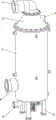
图1为本发明的一种立体结构示意图;Fig. 1 is a kind of three-dimensional structure schematic diagram of the present invention;
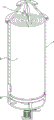
图2为本发明的过滤壳体剖视立体结构示意图;Fig. 2 is a schematic diagram of a three-dimensional structure of a filter housing in section according to the present invention;
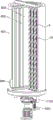
图3为本发明的过滤组件与清理组件位置关系结构示意图;Fig. 3 is a structural schematic diagram of the positional relationship between the filter assembly and the cleaning assembly of the present invention;
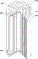
图4为本发明的过滤组件部分剖视立体结构示意图;Fig. 4 is a schematic diagram of a partially cut-away three-dimensional structure of a filter assembly of the present invention;
图5为本发明的过滤壳体部分剖视立体结构示意图;Fig. 5 is a schematic diagram of a partially cut-away three-dimensional structure of the filter housing of the present invention;
图6为本发明的清理组件一部分立体结构示意图;Fig. 6 is a schematic diagram of a part of the three-dimensional structure of the cleaning assembly of the present invention;
图7为本发明图6中A处放大立体结构示意图;Fig. 7 is a schematic diagram of an enlarged three-dimensional structure at A in Fig. 6 of the present invention;
图8为本发明的清理组件另一部分立体结构示意图;Fig. 8 is a perspective view of another part of the cleaning assembly of the present invention;
图9为本发明图8中B处剖视立体结构示意图;Fig. 9 is a schematic diagram of a cross-sectional three-dimensional structure at B in Fig. 8 of the present invention;
图10为本发明的清理管处爆炸示意图。Fig. 10 is a schematic diagram of explosion at the cleaning pipe of the present invention.
附图中各零部件的标记如下:The marks of each component in the accompanying drawings are as follows:
1、过滤壳体,2、盖体,3、进水管,4、净水管,5、排污管,6、支撑架,7、视窗,8、过滤组件,801、环形过滤框,802、连通框,803、过滤筒,804、筒形过滤腔,805、环形过滤腔,806、过滤腔通孔,9、清理部件,901、往复电机,902、第一传动轴,903、隔板,904、清理管,905、汇水腔,906、T形滑槽,907、固定杆,10、预处理部件,1001、转向电机,1002、输出齿轮,1003、传动套筒,1004、第一外齿环,1005、密封壳体,1006、第二外齿环,1007、传动齿轮,1008、固定套筒,1009、密封板,1010、第二传动轴,1011、皮带传动件,1012、螺旋形刮板,11、刮除组件,1101、内齿环,1102、污水腔刮板,1103、异形连接件,1104、T形固定架,1105、待过滤腔刮板,1106、斜向导水板,12、第三传动轴,13、往复丝杠,14、螺纹滑块,15、连接杆,16、翼板。1. Filter housing, 2. Cover body, 3. Water inlet pipe, 4. Water purification pipe, 5. Sewage discharge pipe, 6. Support frame, 7. View window, 8. Filter assembly, 801, Ring filter frame, 802, Connected Frame, 803, filter cartridge, 804, cylindrical filter cavity, 805, annular filter cavity, 806, filter cavity through hole, 9, cleaning component, 901, reciprocating motor, 902, first transmission shaft, 903, partition, 904 , cleaning pipe, 905, catchment chamber, 906, T-shaped chute, 907, fixed rod, 10, pretreatment component, 1001, steering motor, 1002, output gear, 1003, transmission sleeve, 1004, first external gear Ring, 1005, sealing shell, 1006, second external gear ring, 1007, transmission gear, 1008, fixed sleeve, 1009, sealing plate, 1010, second transmission shaft, 1011, belt transmission part, 1012, spiral scraper Plate, 11, scraper assembly, 1101, inner gear ring, 1102, sewage chamber scraper, 1103, special-shaped connector, 1104, T-shaped fixing frame, 1105, to-be-filtered chamber scraper, 1106, oblique water guide plate, 12 , the third drive shaft, 13, reciprocating screw, 14, threaded slider, 15, connecting rod, 16, wing plate.
具体实施方式Detailed ways
下面将结合本发明实施例中的附图,对本发明实施例中的技术方案进行清楚、完整地描述,显然,所描述的实施例仅仅是本发明一部分实施例,而不是全部的实施例。基于本发明中的实施例,本领域普通技术人员在没有做出创造性劳动前提下所获得的所有其他实施例,都属于本发明保护的范围。The following will clearly and completely describe the technical solutions in the embodiments of the present invention with reference to the accompanying drawings in the embodiments of the present invention. Obviously, the described embodiments are only some, not all, embodiments of the present invention. Based on the embodiments of the present invention, all other embodiments obtained by persons of ordinary skill in the art without making creative efforts belong to the protection scope of the present invention.
实施例1Example 1
一种船舶压载水处理系统用自清过滤器,如图1-图10所示,包括有过滤壳体1,过滤壳体1上端通过法兰固定连接有盖体2,盖体2上通过法兰连接有进水管3,过滤壳体1右侧下部设有净水管4,过滤壳体1底部右侧固定连通有排污管5,过滤壳体1底部固定连接有支撑架6,支撑架6用于支撑装置整体,过滤壳体1内部设置有用于过滤压载水的过滤组件8,过滤壳体1贯穿设置有用于清理过滤组件8的清理部件9,清理部件9将过滤壳体1内部腔体上下分隔为上部的待过滤腔和下部的排污腔。A self-cleaning filter for a ship ballast water treatment system, as shown in Figure 1-Figure 10, includes a filter housing 1, the upper end of the filter housing 1 is fixedly connected to a
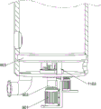
过滤组件8由环形过滤框801、连通框802和过滤筒803组成,过滤壳体1内设置有由外到内直径逐渐变小的三层环形过滤框801,最外层环形过滤框801外壁与过滤壳体1内壁固定连接,其中环形过滤框801内设有环形过滤腔805,过滤壳体1中心轴线处设有过滤筒803,过滤筒803内设有筒形过滤腔804,相邻的环形过滤框801之间通过左右两侧固接的连通框802将环形过滤腔805连通,过滤筒803通过连通框802与相邻的环形过滤框801相固定且连通,整体由外而内为环形过滤框801、连通框802、环形过滤框801、连通框802、环形过滤框801、连通框802和过滤筒803的分布方式,其中过滤筒803内的筒形过滤腔804通过连通框802与最内层环形过滤框801内的环形过滤腔805连通,连通框802水平截面为扇面结构,每个连通框802水平截面均为内小外大,且相邻的连通框802水平截面内小外大,用于由内而外增加流通量,连通框802与相邻环形过滤框801形成扇面形过滤通道,用于减少清理死角,最外层环形过滤框801右侧下部设置有过滤腔通孔806,最外层环形过滤框801与过滤壳体1通过过滤腔通孔806与净水管4连通。The
当过滤组件8进行过滤时,自进水管3通入海水,压力将海水排入过滤组件8并通过环形过滤框801和过滤筒803压入筒形过滤腔804和环形过滤腔805中实现对海水的过滤,过滤后的净水会通过连通框802汇集,再通过过滤腔通孔806外净水管4接通抽水泵进行抽出。通过周向设置的多层过滤框和过滤筒803,提升了过滤壳体1内空间的使用效率和对海水的过滤效率。When the
如图1所示,过滤壳体1右侧下部与盖体2右侧中部分别设置有视窗7,通过视窗7便于观察过滤组件8和污水腔内侧壁的杂质附着情况,以判断是否需要清理或清理过程是否完成。As shown in Figure 1, the lower right side of the filter housing 1 and the middle part of the right side of the
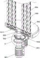
如图6和图8所示,用于对环形过滤框801和过滤筒803的杂质进行清理的清理部件9包括有往复电机901,往复电机901固定安装于支撑架6,往复电机901输出端固定连接有与过滤壳体1转动配合的位于中心轴线的第一传动轴902,第一传动轴902上部为中空结构,且其中空部位侧壁周向开口,用于将汇水腔与排污腔相连通,第一传动轴902上端固定连接有与过滤壳体1转动配合的隔板903,隔板903内设置有汇水腔905,隔板903上固定连接有共两侧每侧均匀间隔分布3个的清理管904,清理管904下端与隔板903固定连接,清理管904分布在过滤组件8内部的缝隙中,隔板903于清理管904贯穿处周围设置有吸污孔,环形过滤框801和过滤筒803形成的缝隙与汇水腔905通过吸污孔连通,用于将剥离下堆积的杂质抽出,提升抽取的效率,清理管904前后两侧对称贯穿设置有T形滑槽906,汇水腔905通过清理管904与待过滤腔相连通,汇水腔905通过第一传动轴902上部与排污腔相连通,清理管904上端固接有固定杆907,固定杆907内设置有用于传动的空腔,与固定杆907的空腔相邻的清理管904竖直穿入空腔内,固定杆907底面位于环形过滤框801、连通框802和过滤筒803的上侧。As shown in Figure 6 and Figure 8, the
当对过滤组件8进行清理时,操作人员启动往复电机901,同时开启在排污管5处接通的抽水泵,当往复电机901启动时通过输出轴带动第一传动轴902周向往复转动,进而带动隔板903周向往复转动,同时使清理管904在环形过滤框801和过滤筒803之间形成的扇面形缝隙内往复移动,将环形过滤框801和过滤筒803上过滤网外壁上附着的杂质通过侧向往复的抽吸,从而在不停止整体过滤工作的前提下通过反洗的方式实现杂质剥落的效果,同时因为其缝隙横截面为扇面结构,在清理管904往复移动时消除清理的死角,更好地清理附着杂质,杂质经清理管904左右两侧竖向开口的T形滑槽906、汇水腔905和第一传动轴902上端的周向开口处抽入排污腔,进而通过排污管5将杂质抽出。When the
实施例2Example 2
在实施例1的基础之上,如图6、图7和图10所示,还包括有预处理部件10,预处理部件10贯穿设置于过滤壳体1中心轴处,预处理部件10用于对环形过滤框801和过滤筒803过滤网外壁上过厚的附着杂质进行清理,预处理部件10包括有转向电机1001,转向电机1001固定安装于支撑架6,转向电机1001输出端固定安装有输出齿轮1002,第一传动轴902外转动设置有贯穿过滤壳体1并与过滤壳体1转动配合的传动套筒1003,传动套筒1003下端固定连接有第一外齿环1004,第一外齿环1004与输出齿轮1002啮合传动,传动套筒1003上位于第一外齿环1004上侧固接有密封壳体1005,传动套筒1003上部密封壳体1005内部设置有第二外齿环1006,密封壳体1005上端第一传动轴902前后两侧固接有与隔板903固定连接的两个固定套筒1008,两个固定套筒1008对称设置在密封壳体1005上,密封壳体1005内部前后对称设置有第二传动轴1010,第二传动轴1010位于固定套筒1008内部,第二传动轴1010与隔板903转动连接,第二传动轴1010下侧固接有与第二外齿环1006啮合传动的传动齿轮1007,螺旋形刮板1012下端转动连接在隔板903上,第二传动轴1010上端通过皮带传动件1011与螺旋形刮板1012下端配合,螺旋形刮板1012上端与固定杆907转动连接,螺旋形刮板1012内侧紧贴清理管904外壁,螺旋形刮板1012外部与环形过滤框801和过滤筒803的外壁留有缝隙。On the basis of Embodiment 1, as shown in Fig. 6, Fig. 7 and Fig. 10, a
当对过滤组件8进行清理时,操作人员同时启动转向电机1001,转向电机1001通过输出轴上的输出齿轮1002将动力传动至传动套筒1003下侧固接的第一外齿环1004,进而将动力通过传动套筒1003传输至传动套筒1003上侧固接的第二外齿环1006,第二外齿环1006通过与左右两侧的传动齿轮1007固接的两个第二传动轴1010将动力传递至的皮带传动件1011,通过皮带传动件1011的带动使6个螺旋形刮板1012外侧对环形过滤框801和过滤筒803的侧壁较厚分布的杂质进行预处理刮除,且为防止直接刮除导致杂质被挤压堵塞环形过滤框801和过滤筒803,因此留下较薄的一层杂质,减小清理部件9工作时的压力,同时通过螺旋形刮板1012内侧对清理管904外壁进行清理,提高整体的清洁效果,预处理后较厚的杂质会因为重力和水流冲击向下堆积,通过清理管904与隔板903贯穿处周围开设的孔,在抽取时将下方堆积的杂质同步抽取,提升杂质的清理效率。When cleaning the
如图6和图8所示,还包括有用于将待过滤腔和排污腔侧壁杂质进行刮除的刮除组件11,刮除组件11包括有内齿环1101,内齿环1101与传动齿轮1007配合传动,污水腔刮板1102与内齿环1101通过异形连接件1103固定连接,异形连接件1103贯穿密封壳体1005,异形连接件1103与密封壳体1005转动连接,异形连接件1103与密封板1009转动连接,污水腔刮板1102远离异形连接件1103的一端紧贴排污腔侧壁,T形固定架1104的中轴穿入且与清理管904通过带轮皮带配合转动连接于固定杆907的空腔内,T形固定架1104另两端固定连接有待过滤腔刮板1105,待过滤腔刮板1105与待过滤腔内侧壁贴合。As shown in Figure 6 and Figure 8, it also includes a scraping
当对过滤组件8进行清理时,通过传动齿轮1007将动力通过内齿环1101传输至污水腔刮板1102,使污水腔刮板1102对排污腔长时间无法清理到的侧壁上杂质进行周向刮除,防止杂质内生物杂质的增殖,为压载水过滤带来负担,处于固定杆907空槽内的螺旋形刮板1012的上端,通过带轮皮带将动力传输至T形固定架1104,使T形固定架1104周向转动,进而带动通过T形固定架1104两侧固定连接的两个前后对称设置的待过滤腔刮板1105对待过滤腔侧壁进行周向刮除,防止杂质附着、堆积和增殖。When cleaning the
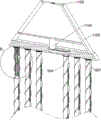
如图10所示,还包括有第三传动轴12,第三传动轴12下端与螺旋形刮板1012固接,第三传动轴12上端固接有往复丝杠13,往复丝杠13转动安装于固定杆907,往复丝杠13外部设置有与之配合的螺纹滑块14,螺纹滑块14前后两侧对称设置有竖直方向上的连接杆15,连接杆15顶端与螺纹滑块14顶端平齐,连接杆15相较螺纹滑块14的外侧固定连接有由上到下间距逐渐减小的翼板16,翼板16与T形滑槽906滑动配合,用于提升抽取压力和抽取效果。As shown in Figure 10, it also includes a
当对过滤组件8进行清理时,为提升对杂质的抽取压力,通过第三传动轴12与其上端固定连接的往复丝杠13一同转动,使与往复丝杠13转动配合的螺纹滑块14上下往复移动,进而通过连接杆15使处于清理管904前后两侧的T形滑槽906内的翼板16上下滑动,翼板16同时限制螺纹滑块14的移动方式为上下移动,每两个相邻的翼板16之间的距离由上至下逐渐减小,用于改善因压力传递不当而导致杂质抽取不均匀的问题,通过翼板16增加清理管904抽取的压力,提升清理的效果,通过翼板16上下移动时位置的调整,改变清理管904的开口位置,使清理更加全面。When the
如图8所示,还包括有斜向导水板1106,斜向导水板1106固定于待过滤腔刮板1105上端,当海水通过进水管3向过滤组件8进水时,斜向导水板1106将海水进行导向,对进入的海水起到分流的效果,防止过滤筒803和中部的环形过滤框801作为主要的过滤区域导致杂质在中部堆积过多,起到使过滤组件8上附着的杂质更加均匀的效果。As shown in Figure 8, it also includes an inclined
尽管已经参照本公开的特定示例性实施例示出并描述了本公开,但是本领域技术人员应该理解,在不背离所附权利要求及其等同物限定的本公开的精神和范围的情况下,可以对本公开进行形式和细节上的多种改变。因此,本公开的范围不应该限于上述实施例,而是应该不仅由所附权利要求来进行确定,还由所附权利要求的等同物来进行限定。While the present disclosure has been shown and described with reference to certain exemplary embodiments thereto, it should be understood by those skilled in the art that other modifications may be made without departing from the spirit and scope of the present disclosure as defined by the appended claims and their equivalents. Various changes in form and details have been made to this disclosure. Therefore, the scope of the present disclosure should not be limited to the above-described embodiments, but should be determined not only by the appended claims, but also by the equivalents of the appended claims.
Claims (2)
Priority Applications (1)
| Application Number | Priority Date | Filing Date | Title |
|---|---|---|---|
| CN202310083383.2A CN115804980B (en) | 2023-02-08 | 2023-02-08 | Self-cleaning filter for ship ballast water treatment system |
Applications Claiming Priority (1)
| Application Number | Priority Date | Filing Date | Title |
|---|---|---|---|
| CN202310083383.2A CN115804980B (en) | 2023-02-08 | 2023-02-08 | Self-cleaning filter for ship ballast water treatment system |
Publications (2)
| Publication Number | Publication Date |
|---|---|
| CN115804980A CN115804980A (en) | 2023-03-17 |
| CN115804980B true CN115804980B (en) | 2023-05-12 |
Family
ID=85487701
Family Applications (1)
| Application Number | Title | Priority Date | Filing Date |
|---|---|---|---|
| CN202310083383.2A Active CN115804980B (en) | 2023-02-08 | 2023-02-08 | Self-cleaning filter for ship ballast water treatment system |
Country Status (1)
| Country | Link |
|---|---|
| CN (1) | CN115804980B (en) |
Families Citing this family (3)
| Publication number | Priority date | Publication date | Assignee | Title |
|---|---|---|---|---|
| CN117509774A (en) * | 2023-12-04 | 2024-02-06 | 河南永泽环境科技有限公司 | A domestic sewage treatment device |
| CN117585117B (en) * | 2024-01-18 | 2024-03-19 | 常州泰尔格重工机械有限公司 | Cleaning robot for ship and working method thereof |
| CN118912983B (en) * | 2024-08-20 | 2025-08-26 | 济南市市政工程设计研究院(集团)有限责任公司 | An anti-internal leakage plate heat exchanger for heating |
Family Cites Families (11)
| Publication number | Priority date | Publication date | Assignee | Title |
|---|---|---|---|---|
| GB1194676A (en) * | 1966-06-29 | 1970-06-10 | G & J Weir Ltd | Filtering Press |
| CN101874948B (en) * | 2009-12-11 | 2012-06-27 | 付灵芝 | Barrel type filtering assembly |
| DE202011000268U1 (en) * | 2011-02-04 | 2012-05-16 | Boll & Kirch Filterbau Gmbh | Backwash filter with rinsing device |
| CN202460263U (en) * | 2012-03-13 | 2012-10-03 | 上海同臣环保科技有限公司 | a filter |
| CN206121270U (en) * | 2016-08-31 | 2017-04-26 | 浙江鹰鹏船舶设备制造有限公司 | Filter of ship ballast water treatment facility |
| CN209985028U (en) * | 2018-12-04 | 2020-01-24 | 杨小霞 | Automatic jet cleaning filter |
| CN109481975A (en) * | 2019-01-08 | 2019-03-19 | 贵州大学 | A kind of waterworks purification of water quality processing stagewise filter device |
| CN112378072A (en) * | 2020-11-16 | 2021-02-19 | 大任空调技术(深圳)有限公司 | Energy-saving control system of central air conditioner |
| CN216778163U (en) * | 2021-12-16 | 2022-06-21 | 中科世沃生态科技江苏有限公司 | Filtering device for water storage |
| CN216604269U (en) * | 2022-01-19 | 2022-05-27 | 天津市盛世达水处理设备有限公司 | Vertical cylinder type filter |
| CN115591301B (en) * | 2022-12-13 | 2023-04-11 | 威海中远海运重工科技有限公司 | Filter for ship ballast water management system and antifouling method |
-
2023
- 2023-02-08 CN CN202310083383.2A patent/CN115804980B/en active Active
Also Published As
| Publication number | Publication date |
|---|---|
| CN115804980A (en) | 2023-03-17 |
Similar Documents
| Publication | Publication Date | Title |
|---|---|---|
| CN115804980A (en) | Self-cleaning filter for ship ballast water treatment system | |
| CN118371041B (en) | A kind of anti-blocking municipal sewage filtering equipment | |
| CN111701333A (en) | Sewage filtering equipment capable of avoiding flocculation adhesion | |
| CN114477500A (en) | Energy-saving sewage treatment equipment and method | |
| CN220265513U (en) | Ballast water filter | |
| CN212741000U (en) | Sewage treatment's environmental protection equipment | |
| CN117018707A (en) | Filter suitable for deionized water cooling system | |
| CN115573417B (en) | Reservoir dredging equipment for water conservancy construction | |
| CN119219093B (en) | An open circulation cooling water purification device | |
| CN110882568B (en) | Waste water filtration system with self-cleaning function | |
| CN213375265U (en) | Municipal administration sewage treatment plant | |
| CN221998979U (en) | Sedimentation tank edulcoration device and sedimentation tank | |
| CN217391799U (en) | Dirt-absorbing type micro-filter | |
| CN218166101U (en) | Desilting device for industrial wastewater treatment | |
| CN219326673U (en) | Industrial wastewater treatment pond | |
| CN215828476U (en) | High-efficient sedimentation tank with filtering capability | |
| CN115745154A (en) | MBR membrane bioreactor sewage treatment plant | |
| CN214551412U (en) | A sludge separation device for sewage treatment | |
| CN215026633U (en) | High-efficient filterable microstrainer | |
| CN115671859A (en) | Filter pipeline that hydraulic engineering used | |
| CN110882565B (en) | Wastewater treatment equipment | |
| CN220878066U (en) | Municipal wastewater filtering treatment device | |
| CN109569302B (en) | External pressure ultrafiltration membrane element | |
| CN220201609U (en) | River sewage ecological treatment device | |
| CN120364900B (en) | Multistage filtering equipment for pure water treatment |
Legal Events
| Date | Code | Title | Description |
|---|---|---|---|
| PB01 | Publication | ||
| PB01 | Publication | ||
| SE01 | Entry into force of request for substantive examination | ||
| SE01 | Entry into force of request for substantive examination | ||
| GR01 | Patent grant | ||
| GR01 | Patent grant |