CN115734832A - Replaceable tool head with serrated coupling portion and tool holder therefor - Google Patents
Replaceable tool head with serrated coupling portion and tool holder therefor Download PDFInfo
- Publication number
- CN115734832A CN115734832A CN202180047108.4A CN202180047108A CN115734832A CN 115734832 A CN115734832 A CN 115734832A CN 202180047108 A CN202180047108 A CN 202180047108A CN 115734832 A CN115734832 A CN 115734832A
- Authority
- CN
- China
- Prior art keywords
- tool head
- serrated
- tool
- wall
- coupling
- Prior art date
- Legal status (The legal status is an assumption and is not a legal conclusion. Google has not performed a legal analysis and makes no representation as to the accuracy of the status listed.)
- Pending
Links
Images


Classifications
-
- B—PERFORMING OPERATIONS; TRANSPORTING
- B23—MACHINE TOOLS; METAL-WORKING NOT OTHERWISE PROVIDED FOR
- B23B—TURNING; BORING
- B23B27/00—Tools for turning or boring machines; Tools of a similar kind in general; Accessories therefor
- B23B27/14—Cutting tools of which the bits or tips or cutting inserts are of special material
- B23B27/16—Cutting tools of which the bits or tips or cutting inserts are of special material with exchangeable cutting bits or cutting inserts, e.g. able to be clamped
-
- B—PERFORMING OPERATIONS; TRANSPORTING
- B23—MACHINE TOOLS; METAL-WORKING NOT OTHERWISE PROVIDED FOR
- B23B—TURNING; BORING
- B23B31/00—Chucks; Expansion mandrels; Adaptations thereof for remote control
- B23B31/02—Chucks
- B23B31/10—Chucks characterised by the retaining or gripping devices or their immediate operating means
- B23B31/107—Retention by laterally-acting detents, e.g. pins, screws, wedges; Retention by loose elements, e.g. balls
- B23B31/1071—Retention by balls
-
- B—PERFORMING OPERATIONS; TRANSPORTING
- B23—MACHINE TOOLS; METAL-WORKING NOT OTHERWISE PROVIDED FOR
- B23B—TURNING; BORING
- B23B29/00—Holders for non-rotary cutting tools; Boring bars or boring heads; Accessories for tool holders
- B23B29/04—Tool holders for a single cutting tool
- B23B29/046—Tool holders for a single cutting tool with an intermediary toolholder
-
- B—PERFORMING OPERATIONS; TRANSPORTING
- B23—MACHINE TOOLS; METAL-WORKING NOT OTHERWISE PROVIDED FOR
- B23B—TURNING; BORING
- B23B29/00—Holders for non-rotary cutting tools; Boring bars or boring heads; Accessories for tool holders
- B23B29/04—Tool holders for a single cutting tool
- B23B29/06—Tool holders equipped with longitudinally-arranged grooves for setting the cutting tool
-
- B—PERFORMING OPERATIONS; TRANSPORTING
- B23—MACHINE TOOLS; METAL-WORKING NOT OTHERWISE PROVIDED FOR
- B23B—TURNING; BORING
- B23B31/00—Chucks; Expansion mandrels; Adaptations thereof for remote control
- B23B31/02—Chucks
- B23B31/10—Chucks characterised by the retaining or gripping devices or their immediate operating means
- B23B31/107—Retention by laterally-acting detents, e.g. pins, screws, wedges; Retention by loose elements, e.g. balls
- B23B31/1075—Retention by screws
-
- B—PERFORMING OPERATIONS; TRANSPORTING
- B23—MACHINE TOOLS; METAL-WORKING NOT OTHERWISE PROVIDED FOR
- B23B—TURNING; BORING
- B23B2231/00—Details of chucks, toolholder shanks or tool shanks
- B23B2231/02—Features of shanks of tools not relating to the operation performed by the tool
- B23B2231/0204—Connection of shanks to working elements of tools
-
- B—PERFORMING OPERATIONS; TRANSPORTING
- B23—MACHINE TOOLS; METAL-WORKING NOT OTHERWISE PROVIDED FOR
- B23B—TURNING; BORING
- B23B2240/00—Details of connections of tools or workpieces
-
- B—PERFORMING OPERATIONS; TRANSPORTING
- B23—MACHINE TOOLS; METAL-WORKING NOT OTHERWISE PROVIDED FOR
- B23B—TURNING; BORING
- B23B2260/00—Details of constructional elements
- B23B2260/124—Screws
-
- B—PERFORMING OPERATIONS; TRANSPORTING
- B23—MACHINE TOOLS; METAL-WORKING NOT OTHERWISE PROVIDED FOR
- B23B—TURNING; BORING
- B23B2260/00—Details of constructional elements
- B23B2260/132—Serrations
-
- B—PERFORMING OPERATIONS; TRANSPORTING
- B23—MACHINE TOOLS; METAL-WORKING NOT OTHERWISE PROVIDED FOR
- B23B—TURNING; BORING
- B23B2270/00—Details of turning, boring or drilling machines, processes or tools not otherwise provided for
- B23B2270/06—Use of elastic deformation
Landscapes
- Engineering & Computer Science (AREA)
- Mechanical Engineering (AREA)
- Cutting Tools, Boring Holders, And Turrets (AREA)
- Workshop Equipment, Work Benches, Supports, Or Storage Means (AREA)
- Clamps And Clips (AREA)
- Milling Processes (AREA)
Abstract
A tool head (10) has a longitudinal axis L, a front end 20 and a rear end 36, and a top surface 12, a bottom surface 14 and an outer peripheral surface 16. The peripheral surface (16) has first and second side walls 22, 26 provided with respective first and second indented portions 24, 28, each of which is divided into spaced apart top and bottom side wall portions 22a,26a, 22b,26b. The outer peripheral surface also has a stopper wall (30) in the rearward direction D R Faces, extends transversely to the second side wall and is provided with a stop serrated portion (32). A rear wall (34) formed at the rear end portion connects the first and second side walls. The tool head further comprises a blade holding portion (17) and a coupling portion (19), the blade holding portion (17) being proximal to the front end, the coupling portion (19)The lug (19) extends in the direction of the rear end and comprises vertically spaced apart top and bottom coupling arms 40, 42 separated by a coupling recess (38) which opens out towards the rear wall.
Description
Technical Field
The subject matter of the present application relates generally to a tool holder and, in particular, to a tool holder having a separable tool head carrying a cutting tool.
Background
In the field of metal cutting, tool holders are known having a cutter bar removably connected to a holder cutter. The fastener is used to clamp the mounting surface of the holder tool between the two inner walls of the pocket of the cutter bar. Serrated surfaces are provided on the inner walls of the grooves and on the mounting surface. Such tools are disclosed in CN209598226 and CN106180773, for example.
Tool holders are also known that have a bolt passing across the end of the shank, allowing assembly without removing the bolt. Such tools are disclosed, for example, in US4,575,293 and US7,240,594.
It is an object of the subject matter of the present application to provide a tool holder having a quick removal mechanism while providing an improved coupling between the tool head and the tool holder.
Disclosure of Invention
According to a first aspect of the subject matter of the present application, there is provided a tool head having a longitudinal tool head axis extending in a rearward to forward direction, the tool head comprising:
a top surface, a bottom surface, and a peripheral surface extending therebetween, the peripheral surface further comprising:
a first sidewall extending along a tool head axis and having a first serrated portion;
a second sidewall located opposite the first sidewall with respect to a tool head axis in a top view of the tool head taken perpendicular to the top surface, the second sidewall extending along the tool head axis and having a second indented portion;
a stopper side wall facing in a rearward direction and extending transverse to the second side wall, the stopper side wall including a stopper serrated portion; and
a rear wall extending between the first and second side walls at a rear end of the tool head;
a blade seat located at an intersection of the top surface and the peripheral surface at a front end of the tool head; and
an attachment recess at a rear end of the tool head, the attachment recess being open to the rear wall, the first side wall, and the second side wall.
According to a second aspect of the subject matter of the present application, there is provided a cutting tool comprising a tool holder, a tool head according to the present application, and a cutting blade mounted in a blade seat of the tool head.
Drawings
For a better understanding of the present application and to show how the same may be carried into effect, reference will now be made to the accompanying drawings, in which:
FIG. 1 is a first perspective view of a tool head according to the present application;
FIG. 2 is a second perspective view of the tool head of FIG. 1;
FIG. 3 is a top view of the tool head of FIG. 1;
FIG. 4 is a first side view of the tool head of FIG. 1, taken from perspective IV of FIG. 3;
FIG. 5 is a second side view of the tool head of FIG. 1, taken from view V of FIG. 3;
FIG. 6 is a perspective view of a cutting tool according to the present application;
FIG. 7 is an exploded view of the cutting tool of FIG. 6;
FIG. 8 is a top view of the cutting tool of FIG. 6;
FIG. 9 is a cross-sectional view of the cutting tool of FIG. 6 taken along line IX-IX of FIG. 8;
FIG. 10A is an elevation view of a cutting tool according to another embodiment of the present application;
FIG. 10B is an exploded view of the cutting tool of FIG. 10A;
FIG. 10C is another exploded view of the cutting tool of FIG. 10A;
FIG. 11A is a top exploded view of a cutting tool according to yet another embodiment of the present application; and
fig. 11B is an exploded elevation view of the cutting tool of fig. 11A.
It will be appreciated that for simplicity and clarity of illustration, elements shown in the figures have not necessarily been drawn to scale. For example, the dimensions of some of the elements may be exaggerated relative to other elements for clarity, or several physical components may be included in one functional block or element. Further, where considered appropriate, reference numerals may be repeated among the figures to indicate corresponding or analogous elements.
Detailed Description
In the following description, various aspects of the subject matter of the present application will be described. For purposes of explanation, specific configurations and details are set forth in sufficient detail to provide a thorough understanding of the subject matter of the present application. It will also be apparent, however, to one skilled in the art that the subject matter of the present application may be practiced without the specific configurations and details presented herein.
Attention is first drawn to fig. 1-5, showing a tool head 10 according to the present application. The tool head 10 has a rearward direction D R To the forward direction D F An extended longitudinal tool head axis L, and a longitudinal tool head axis perpendicular to the longitudinal tool head axis L and in an upward direction D U To the downward direction D D An extended vertical tool head axis V. The tool head 10 has a front end 20 and a rear end 36, the rear end 36 being located opposite the front end 20 along a longitudinal tool head axis L.
The tool head 10 includes a top surface 12, a bottom surface 14, and a peripheral surface 16 extending therebetween. A vertical tool head axis V passes through the top and bottom surfaces 12, 14 in a generally perpendicular direction.
The outer peripheral surface 16 also includes a first sidewall 22 extending along the tool head axis L and having a first serrated portion 24. In a top view of the tool head 10 taken perpendicular to the top surface 12, the second side wall 26 is located opposite the first side wall 22 with respect to the tool head axis L. The second side wall 26 extends along the tool head axis L and has a second serrated portion 28 thereon.
Stopper wall 30 in rearward direction D R Faces and extends transversely to the second side wall 26. The stopper wall 30 includes a stopper serrated portion 32 thereon. At a rear end 36 of the tool head 10, a rear wall 34 of the tool head 10 extends between the first and second side walls 22, 26.
The tool head 10 further comprises a blade holding portion 17 proximal to the front end 20, and a coupling portion 19 connected to the blade holding portion 17 and extending rearwardly in the direction of a rear end 36 of the tool head 10.
The blade holding portion 17 includes a blade seat 18, the blade seat 18 being located at the intersection of the top surface 12 and the peripheral surface 16 at a front end 20 of the tool head 10.
The blade seat may have a screw aperture 56 that opens out to the blade seat 18.
The screw apertures 56 may extend toward the bottom surface 14.
The coupling portion 19 comprises a rearwardly extending top coupling arm 40 and a rearwardly extending bottom coupling arm 42 spaced from each other along the vertical axis V by a coupling recess 38, the coupling recess 38 being flared towards the rear wall 34 at the rear end 36 of the tool head 10.
The first side wall 22 is divided into spaced apart top and bottom first side wall portions 22a and 22b, each of which is at least partially formed on a corresponding top or bottom linkage arm 40 or 42. The second sidewall 26 is divided into spaced apart top and bottom second sidewall portions 26a and 26b, each of which is at least partially formed on a corresponding top or bottom linkage arm 40 or 42. Thus, the first serrated portion 24 formed on the first sidewall 22 includes a top serrated first sidewall section 24a and a bottom serrated first sidewall section 24b that are at least partially formed on the corresponding top or bottom link arm 40, 42. Similarly, the second serrated portion 28 formed on the second sidewall 26 has a top serrated second sidewall section 28a and a bottom serrated second sidewall section 28b that are at least partially formed on a corresponding top linkage arm 40 or bottom linkage arm 42.
The stop wall 30 may be divided into a top stop portion 30a and a bottom stop portion 30b, each of which may be at least partially formed on a corresponding top link arm 40 or bottom link arm 42. Thus, the stopper serrated portion 32 is divided into a top stopper serrated section 50 and a bottom stopper serrated section 52.
The rear wall 34 is divided by a coupling recess 38 into a top rear wall portion 34a and a bottom rear wall portion 34b, which are formed on respective top and bottom coupling arms 40 and 42. Thus, the coupling recess 38 opens out to the rear wall 34, the first side wall 22, and the second side wall 26, thereby forming spaced apart top and bottom coupling arms 40, 42.
As best seen in fig. 4 and 5, the first and second serrated portions 24 and 28 each include a plurality of serrated grooves 33 that extend in a direction parallel to the longitudinal tool head axis L. The stop serrated portion 32 also includes a plurality of serrated grooves that extend transverse to the longitudinal tool head axis L and transverse to the vertical tool head axis V.
As shown in fig. 3 and 5, the outer peripheral surface 16 includes a front wall 44 at the front end 20 of the tool head 10. The front support wall 46 is in the rearward direction D R Extending from the front wall 44.
In some embodiments of the present invention, blade seat 18 is located at the intersection of top surface 12 with front wall 44 and front support wall 46.
In some embodiments of the present invention, as shown in fig. 1-9, the rear wall 34 of the coupling portion 19 of the tool head 10 lacks serrations.
Attention is now drawn to FIGS. 6-9, which illustrateA cutting tool 100 according to an embodiment of the present application. Cutting tool 100 includes tool holder 102, tool head 10, and cutting blade 62 mounted in blade seat 18 of tool head 10. The tool holder 102 has a rearward direction D R To the forward direction D F An extended longitudinal holder axis H, and a tool head receiving portion 104 at a holder forward end 106 of the tool holder 102.
The tool head receiving portion 104 has a retainer stop wall 118 in the forward direction D F Facing and having a tool holder stop serrated portion 120 thereon. The tool head receiving portion 104 further includes a first gripping arm 108 and a second gripping arm 110. The first and second gripper arms 108, 110 are located on opposite sides of the holder axis H and are spaced apart by a tool head receiving pocket 112.
The first clamping arm 108 has a first inner serrated portion 114 facing the tool head receiving pocket 112, and a through bore 122 extending transverse to the holder axis H. The second gripper arm 110 has a second inner serrated portion 116 facing the tool head receiving pocket 112, and a threaded bore 124 extending transverse to the holder axis H. The threaded bore 124 and the through bore 122 extend along a common lateral axis M.
As shown in fig. 6, 8 and 9, the tool head 10 is coupled with a tool holder 102. To this end, the tool head 10 is placed in front of the tool head receiving portion 104 (as in fig. 7) and in a rearward direction D along the holder axis H R And (4) moving upwards. In other words, the tool head 10 slidingly engages the tool head receiving portion 104.
Upon insertion of the tool head 10 in the tool head receiving portion 104, the first serrated portion 24 of the tool head interacts with the first internal serrated portion 114 of the tool holder, the second serrated portion 28 of the tool head interacts with the second internal serrated portion 116 of the tool holder, and the stop serrated portion 32 of the tool head interacts with the tool holder stop serrated portion 120. Such tool coupling is provided between the tool holder 102 and the tool head 10 along a plurality of surfaces thereof (including therebetween)At the respective stopper wall 30, 118). The serrated surface coupling prevents rotation between the tool holder 102 and the tool head 10 in a direction transverse to the serrations (such as in the upward direction D) U To the downward direction D D Upper) relative movement.
The clamping member 126 passes through the through hole 122 of the first clamping arm 108 and partially interacts with the threaded aperture 124 of the second clamping arm 110. The gripping member 126 is also received within the coupling recess 38 of the tool head 10.
It is noted that the coupling recess 38 provides a degree of flexibility with respect to movement of the top and bottom coupling arms 40, 42 in a direction perpendicular to the tool head axis L. Thus, as the tool head 10 is advanced into the tool head receiving portion 104, the top and bottom coupling arms 40, 42 may move in a direction perpendicular to the tool head axis L, allowing for a smooth coupling between the first serrated portion 24 of the tool head and the first internal serrated portion 114 of the tool holder, and between the second serrated portion 28 of the tool head and the second internal serrated portion 116 of the tool holder.
The clamping member 126 may be inserted into the through bore 122 and the threaded bore 124 prior to insertion of the tool head 10 into the tool head receiving portion 104. In such a case, the coupling recess 38 passes over the clamping member 126. More specifically, the top and bottom linkage arms 40, 42 of the tool head pass on either side of (e.g., above and below, respectively) the gripping member 126.
Alternatively, the clamping member 126 may be inserted into the through bore 122 and the threaded bore 124 after the tool head 10 is inserted into the tool head receiving portion 104. In such a case, the clamping member 126 slides along the lateral axis M through the coupling recess 38.
As the gripping member 126 is threadedly engaged in the threaded bore 124, the first and second gripping arms 108, 110 are pulled toward one another, thereby pressing against the tool head 10 and gripping the tool head 10.
The interaction between the first serrated portion 24 of the tool head and the first internal serrated portion 114 of the tool holder, and the interaction between the second serrated portion 28 of the tool head and the second internal serrated portion 116 of the tool holder, form contact between the tool head 10 and the tool holder 102 along repeatable and multiple contact surfaces. Similarly, this applies to the interaction between the tool head stop serrated portion 32 and the tool holder stop serrated portion 120.
In some embodiments, a stop serrated portion 32 of the tool head is provided proximal to the blade seat 18. A tool holder stop serrated portion 120 is provided at the forward end of second clamp arm 110 to provide repeatable contact near blade seat 18. The serrated contact along the stop wall 30 supports the tool head 10 during the cutting operation, thereby resisting machining forces exerted on the cutting blade 62.
It will be appreciated that the gripping member 126 is received within the coupling recess 38 without contacting the tool head 10. Thus, when the gripping member 126 is partially unscrewed from the threaded aperture 124, the first and second gripping arms 108, 110 no longer grip the tool head 10. In this state, the tool head 10 may be removed from the tool holder 102 without completely removing the clamping member 126. Similarly, and as mentioned above, the tool head 10 may be installed into the tool holder 102 when the clamping member 126 has been partially threaded into the threaded bore 124. This provides a quick release or quick change over mechanism for coupling the tool head 10 with the tool holder 102.
As disclosed in the present application, such modular quick-change configurations involve the advantage of using the same tool holder 102 with different tool heads 10, while the tool holder remains connected to the machine. Different tool heads 10 may have various cutting configurations of cutting blades, which are not limited to the cutting configurations shown in the figures. That is, different tool heads 10 may have different insert pocket configurations for carrying different cutting inserts and performing different cutting operations. This provides a modular cutting tool allowing various cutting operations to be performed while the same tool holder is still connected to the machine.
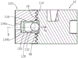
Referring also to fig. 2,3 and 7-9, in some embodiments of the invention, the first sidewall 22 of the tool head 10 has a side recess 48 thereon, the side recess 48 being axially forward of the coupling recess 38. The first clamping arm 108 of the cutting tool 100 has a retaining aperture 134 therethrough and flared toward the first inner serrated portion 114. The retention bore 134 extends transverse to the retainer axis H along a retention bore axis B.
The retaining member 128 is inserted into the retaining aperture 134. When the tool head 10 is mounted in the tool head receiving pocket 112, the side recess 48 faces the retaining aperture 134, and thus the retaining member 128.
In some embodiments, the retaining member 128 includes a housing 130 and a spring-loaded spherical member 132. As seen in fig. 9, the retaining aperture 134 may include a narrow neck portion 134a connected to an enlarged body portion 134b, the enlarged body portion 134b being configured and dimensioned to receive the housing 130 of the retaining member 128. As particularly shown in fig. 8-9, the spherical member 132 is urged by a spring (not shown) into the side recess 48 of the tool head. In this manner, the spherical member 132 exerts a retaining force F on the tool head 10 along the retaining bore axis B R . The tool head 10 is thus pressed against the second gripper arm 110 of the tool holder 102.
Due to the force exerted by the spherical member 132, the tool head 10 remains in place within the tool head receiving pocket 112 even when the clamping member 126 is not fully threaded into the threaded bore 124. In this manner, the retaining member 128 serves to retain the tool head 10 and prevent the tool head 10 from falling out by sliding out of the tool holder 102 along the holder axis H (even when not fully clamped by the clamping member 126). When in the forward direction D F Such an anti-fall mechanism is particularly advantageous as the direction of gravity (i.e. downwards).
In some embodiments, the retention bore 134 is forward of the through bore 122 along the retainer axis H.
In some embodiments of the invention, the stop serrated portion 32 of the tool head 10 may have a top stop serrated section 50 extending along the top surface 12, and a bottom stop serrated section 52 extending along the bottom surface 14. The bottom stop serrated section 52 is spaced from the top stop serrated section 50 by a stop wall notch 54. The stopper wall notch 54 does not have serrations thereon. This ensures a spaced apart, spaced apart contact area between the tool head stop serrated portion 32 and the tool holder stop serrated portion 120.
Further, the retainer stop wall 118 of the tool holder 102 may have a retainer stop recess 136 that separates the tool holder stop serrated portion 120 into two spaced apart portions. This forms a free space for inserting the holding member 128 into the holding aperture 134. That is, the retainer stop recess 136 provides uninterrupted access to the retention bore 134 along the retention bore axis B (fig. 7) such that the retention member 128 may be inserted into the retention bore 134 in a straight line.
In some embodiments of the invention, as indicated for example in fig. 3 and 8, the rear wall 34 of the tool head 10 has a V-shape comprising a shape in the rearward direction D R A converging first rear wall portion 58 and a second rear wall portion 60. This may allow for easier insertion of the tool head 10 into the tool head receiving pocket 112, as the tool head 10 is slidingly guided into the tool head receiving pocket 112 with no sharp edges at its rear end 36.
Attention is now directed to fig. 10A, 10B and 10C, depicting a cutting tool 200 according to another embodiment of the present application. The cutting tool 200 includes a tool holder 202 and a tool head 210. The tool holder 202 is similar to the tool holder 102 except for the location of the holder stop wall. In this embodiment, the retainer stop wall 118' is located at the inner (rear) end of the tool head receiving pocket 112.
The tool head 210 is similar to the tool head 10 except for the location of the stop walls. In this embodiment, the stop wall 30' is located on the rear wall 34 of the tool head 210. In this case, the stopper serrated portion 32 includes a plurality of serrated grooves 33 (formed on the rear wall 34) that are elongated in a direction perpendicular to the tool head longitudinal axis L and the vertical tool head axis V. Further, as seen in fig. 10C, the stop serrated portion 32 is located between the first serrated portion 24 and the second serrated portion 28 on both the top linkage arm 40 and the bottom linkage arm 42. Further, in this embodiment, the top stop serrated section 50 and the bottom stop serrated section 52 are vertically spaced from each other by the coupling recess 38.
The coupling of the tool head 210 to the tool holder 202 is similar to the coupling described herein above with respect to the tool head 10 and the tool holder 102. The difference is that the interaction between the tool head stop serrated portion 32 and the tool holder stop serrated portion 120 occurs at the inner (rear) end of the tool head receiving pocket 112. In practice, this embodiment is an alternative to the embodiment shown in fig. 1-9, resulting in the same technical effect of tool coupling by maintaining the serrated surface interaction between the tool holder 202 and the tool head 210 also at the stop surfaces of the tool holder 202 and the tool head 210.
Attention is also drawn to fig. 11A and 11B, showing a cutting tool 300 according to yet another embodiment of the present application. The cutting tool 300 includes a tool holder 302 and a tool head 310. In contrast to the tool holder 102, the tool holder 302 further includes a central clamp arm 312 located between the first clamp arm 108 and the second clamp arm 110. The central retaining arm 312 extends in the forward direction D from the inner (rear) end of the tool head receiving pocket 112 F The upper edge extends in the longitudinal direction. The central gripping arm 312 has a retainer central serrated portion 314.
In the tool head 310, the top linkage arm 40 is divided into a first top linkage arm portion 316 and a second top linkage arm portion 318 spaced apart from each other. Likewise, the bottom coupling arm 42 is divided into a first bottom coupling arm portion 320 and a second bottom coupling arm portion 322 spaced apart from each other. The linkage arm portions 316,318,320 and 322 have a tool head central serrated portion 324.
The coupling of the tool head 310 to the tool holder 302 is similar to the coupling described herein above with respect to the tool head 10 and the tool holder 102 (i.e., in the following manner). Tool head 310 is in a rearward direction D along holder axis H R Is inserted into the tool head receiving pocket 112. The central gripping arm 312 of the tool holder 302 is received in the space between the first 316 and second 318 top link arm portions, and between the first 320 and second 322 bottom link arm portions.
The retainer central serrated portion 314 of the tool retainer 302 interacts with the tool head central serrated portion 324 of the tool head 310. This provides a strong coupling between the tool head 310 and the tool holder 302 due to the enlarged serrated contact area therebetween.
Although the subject matter of the present application has been described with a certain degree of particularity, it should be understood that various alterations and modifications could be made without departing from the spirit or scope of the invention as hereinafter claimed.
Claims (20)
1. A tool head (10, 210, 310) having a rearward direction (D) R ) To the forward direction (D) F ) An extended longitudinal tool head axis (L), perpendicular to the longitudinal tool head axis (L) and in an upward direction (D) U ) To the downward direction (D) D ) An extended vertical tool head axis (V), a front end (20), and a rear end (36) located opposite the front end (20); the tool head (10, 210, 310) comprises:
a top surface (12), a bottom surface (14), and a peripheral surface (16) extending therebetween, the peripheral surface (16) comprising:
a first side wall (22) and a second side wall (26) located on opposite sides of the longitudinal tool head axis (L) in a top view of the tool head (10), the first side wall (22) having a first serrated portion (24) and the second side wall (26) having a second serrated portion (28);
a stopper wall (30, 30') along the rearward direction (D) R ) Facing and extending transversely to the second side wall (26), the stopper wall (30) having a stopper serrated portion (32); and
a rear wall (34) extending between the first and second side walls (22, 26) at the rear end (36) of the tool head (10);
a blade holding portion (17) comprising a blade seat (18) located at an intersection of the top surface (12) and the peripheral surface (16); and
a coupling portion (19) connected to the blade holding portion (17) and comprising a rearwardly extending top coupling arm (40) and a bottom coupling arm (42) spaced from each other along the vertical axis (V) by a coupling recess (38), the coupling recess (38) flaring out to the rear wall (34) at the rear end (36).
2. The tool head (10, 210, 310) according to claim 1, wherein:
the first sidewall (22) is divided into vertically spaced apart top (22 a) and bottom (22 b) first sidewall portions, each first sidewall portion being at least partially formed on a corresponding top (40) or bottom (42) coupling portion;
said first serrated portion (24) being divided into a top serrated first side wall section (24 a) and a bottom serrated first side wall section (24 b) which are at least partially formed on respective top and bottom link arms (40, 42);
the second sidewall (26) is divided into vertically spaced apart top (26 a) and bottom (26 b) second sidewall portions, each second sidewall portion being at least partially formed on a corresponding top (40) or bottom (42) coupling portion;
said second serrated portion (28) being divided into a top serrated second side wall section (28 a) and a bottom serrated second side wall section (28 b) which are at least partially formed on respective top and bottom coupling arms (40, 42); and is provided with
The coupling recess (38) flares toward the rear wall (34), the first side wall (22), and the second side wall (26), thereby forming spaced apart top and bottom coupling arms (40, 42).
3. The tool head (10, 210, 310) according to any preceding claim, wherein:
each of the first serrated portion (24) and the second serrated portion (28) comprising a plurality of serrated grooves (33); and is
The sawtooth grooves (33) of the first sawtooth-shaped portion (24) and the sawtooth grooves (33) of the second sawtooth-shaped portion (28) are elongated in a direction parallel to the longitudinal tool head axis (L).
4. The tool head (10, 210, 310) according to claim 3, wherein:
the stopper serrated portion (32) includes a plurality of serrated grooves (33); and is
The saw tooth groove (33) of the stopper serrated portion (32) is elongated in a direction transverse to the longitudinal tool head axis (L).
5. The tool head (10, 210, 310) according to any of the preceding claims, wherein:
the stopper serrated portion (32) has a top stopper serrated section (50) extending along the top surface (12) and a bottom stopper serrated section (52) extending along the bottom surface (14), and
the bottom stop serrated section (52) is spaced from the top stop serrated section (50) by a stop wall notch (54) or the coupling recess (38).
6. The tool head (10, 210, 310) according to any one of the preceding claims, wherein the first side wall (22) comprises a side recess (48) axially in front of the coupling recess (38).
7. The tool head (10, 210, 310) according to any preceding claim, wherein:
the outer peripheral surface (16) further comprises:
a front wall (44) at the front end (20) of the tool head (10), and
a front support wall (46) in the rearward direction (D) from the front wall (44) R ) Extending;the blade holding portion (17) further comprises a blade seat screw aperture (56) flared towards the blade seat (18) and extending towards the bottom surface (14); and is
The blade seat (18) is located at an intersection of the top surface (12) with the front wall (44) and the front support wall (46).
8. The tool head (10) according to any one of the preceding claims, wherein the rear wall (34) comprises a wall extending in the rearward direction (D) R ) A converging first rear wall portion (58) and a second rear wall portion (60).
9. A tool head (10) according to any preceding claim, wherein the rear wall (34) lacks serrations.
10. The tool head (10) according to any preceding claim, wherein the stop wall (30) is located adjacent to the second side wall (26) and forward of the second side wall (26).
11. The tool head (210) according to any one of claims 1 to 7, wherein:
the stopper wall (30') is located on the rear wall (34) of the tool head (210);
the stopper serrated portion (32) is formed on the rear wall (34) and includes a plurality of serration grooves (33); and is
The saw tooth groove (33) of the stopper serrated portion (32) is elongated in a direction perpendicular to the longitudinal tool head axis (L).
12. The tool head (310) according to any one of claims 1 to 7, wherein:
the top linkage arm (40) being divided into a first top linkage arm portion (316) and a second top linkage arm portion (318) spaced apart from each other; and is provided with
The bottom linkage arm (42) is divided into a first bottom linkage arm portion (320) and a second bottom linkage arm portion (322) spaced apart from each other.
13. A cutting tool (100, 200, 300) comprising:
a tool holder (102, 202, 302);
a tool head (10, 210, 310) according to any preceding claim mounted on the tool holder; and
a cutting blade (62) mounted in the blade seat (18) of the tool head (10, 210, 310).
14. The cutting tool (100, 200, 300) according to claim 13, wherein:
the tool holder (102, 202, 302) has a rearward direction (D) R ) To the forward direction (D) F ) An extended longitudinal holder axis (H), and a tool head receiving portion (104) at a holder forward end (106) of the tool holder (102, 202, 302), the tool head receiving portion (104) comprising:
a first clamp arm (108) and a second clamp arm (110) located on opposite sides of the holder axis (H) and spaced apart by a tool head receiving pocket (112);
the first gripper arm (108) having a through-hole (122) extending transversely to the holder axis (H), and a first inner serrated portion (114) facing the tool head receiving pocket (112);
the second gripper arm (110) having a threaded bore (124) extending transverse to the holder axis (H), and a second inner serrated portion (116) facing the tool head receiving pocket (112); and
a retainer stopper wall (118, 118') along the forward direction (D) F ) Facing and having a retainer stop serrated portion (120);
wherein the tool head (10) is mounted in the tool head receiving portion (104) such that:
the first serrated portion (24) interacts with the first inner serrated portion (114),
the second serrated portion (28) interacts with the second inner serrated portion (116),
the retainer serrated portion (32) interacts with the retainer serrated portion (120), and
a clamp member (126) passes through the through-hole (122) of the first clamp arm (108), is received within the coupling recess (38) of the tool head (10), and interacts with the threaded bore (124) of the second clamp arm (110).
15. The cutting tool (100, 200, 300) according to claim 14, wherein:
the first clamp arm (108) having a retention aperture (134) therethrough and opening out to a first inner serrated portion (114);
the cutting tool (100, 200, 300) further comprises a retaining member (128) inserted into the retaining aperture (134), the retaining member (128) pressing against the undercut (48) of the tool head (10, 210, 310).
16. The cutting tool (100, 200, 300) according to claim 15, wherein the retaining member (128) comprises a housing (130) and a spherical member (132), the spherical member (132) being spring loaded in the housing (130) and pressed against the side recess (48) of the tool head (10, 210, 310).
17. The cutting tool (100, 200, 300) according to any one of claims 15 to 16, wherein the retention bore (134) is axially forward of the through hole (122) along the retainer axis (H).
18. The cutting tool (100) according to any one of claims 14 to 17, wherein the retainer stop wall (118) of the tool retainer (102) has a retainer stop recess (136) separating the retainer stop serrated portion (120) into two spaced apart portions.
19. The cutting tool (200) according to any one of claims 14-17, wherein:
the stop wall (30') is located on the rear wall (34) of the tool head (210); and
the retainer stop wall (118') is located at an inner end of the tool head receiving pocket (112).
20. The cutting tool (300) according to any one of claims 14-17, wherein:
the tool holder (302) further comprises a central gripping arm (312) located between the first gripping arm (108) and the second gripping arm (110), the central gripping arm (312) being in the forward direction (D) from a rear end of the tool head receiving pocket (112) F ) Extending;
a top coupling arm (40) of the tool head is divided into a first top coupling arm portion (316) and a second top coupling arm portion (318) spaced apart from each other; and is
The tool head bottom coupling arm (42) is divided into a first bottom coupling arm portion (320) and a second bottom coupling arm portion (322) spaced apart from each other.
Applications Claiming Priority (3)
| Application Number | Priority Date | Filing Date | Title |
|---|---|---|---|
| US202063047294P | 2020-07-02 | 2020-07-02 | |
| US63/047294 | 2020-07-02 | ||
| PCT/IL2021/050674 WO2022003665A1 (en) | 2020-07-02 | 2021-06-06 | Replaceable tool head having serrated coupling portions and a tool holder therefor |
Publications (1)
| Publication Number | Publication Date |
|---|---|
| CN115734832A true CN115734832A (en) | 2023-03-03 |
Family
ID=76730962
Family Applications (1)
| Application Number | Title | Priority Date | Filing Date |
|---|---|---|---|
| CN202180047108.4A Pending CN115734832A (en) | 2020-07-02 | 2021-06-06 | Replaceable tool head with serrated coupling portion and tool holder therefor |
Country Status (10)
| Country | Link |
|---|---|
| US (1) | US11577323B2 (en) |
| EP (1) | EP4175782A1 (en) |
| JP (1) | JP2023531176A (en) |
| KR (1) | KR20230034330A (en) |
| CN (1) | CN115734832A (en) |
| BR (1) | BR112022024358A2 (en) |
| CA (1) | CA3183573A1 (en) |
| IL (1) | IL298829A (en) |
| TW (1) | TW202202250A (en) |
| WO (1) | WO2022003665A1 (en) |
Families Citing this family (2)
| Publication number | Priority date | Publication date | Assignee | Title |
|---|---|---|---|---|
| US11701719B2 (en) * | 2019-12-26 | 2023-07-18 | Iscar, Ltd. | Cutting insert adaptor and tool assembly |
| JP7253157B1 (en) * | 2022-06-22 | 2023-04-06 | 株式会社タンガロイ | Shank and cutting tool with same |
Family Cites Families (22)
| Publication number | Priority date | Publication date | Assignee | Title |
|---|---|---|---|---|
| US1656450A (en) * | 1925-02-28 | 1928-01-17 | Steuer August | Chuck |
| US2181151A (en) * | 1933-07-27 | 1939-11-28 | O K Tool Co Inc | Adjustable shankless bit and holder therefor |
| US3885282A (en) * | 1973-10-23 | 1975-05-27 | Josef Pataky | Machining tool |
| US4575293A (en) | 1984-07-12 | 1986-03-11 | Mario Berti | Machine tool holder having opposed ramp members |
| SE516973C2 (en) * | 1999-02-04 | 2002-03-26 | Sandvik Ab | Cutting and grooving tools provided with toothed coupling surfaces |
| US7240594B2 (en) | 1999-09-01 | 2007-07-10 | Kennametal Inc. | Toolholder assembly |
| SE521183C2 (en) * | 2001-03-15 | 2003-10-07 | Sandvik Ab | Cutting holder with means for adjusting the cutting position holder |
| SE525462C2 (en) * | 2002-06-18 | 2005-02-22 | Sandvik Ab | Tool head for chip separating metal machining tool with clamping screw which is inserted into a nut roll |
| KR100625900B1 (en) * | 2002-06-25 | 2006-09-20 | 엔지케이 스파크 플러그 캄파니 리미티드 | Insert, holder and cutting tool |
| SE526894C2 (en) * | 2004-03-03 | 2005-11-15 | Sandvik Intellectual Property | Cutting tools and tool heads with tubular coolant duct |
| DE102004033929B3 (en) * | 2004-07-14 | 2006-01-12 | SIMTEK Präzisionswerkzeuge GmbH | Tool for machine tool unit has at least one clamping device parallel to lower base and transverse to longitudinal axis of tool holder |
| CN102049540A (en) * | 2006-02-28 | 2011-05-11 | 钴碳化钨硬质合金公司 | Tool holder assembly |
| IL185047A (en) * | 2007-08-05 | 2011-09-27 | Iscar Ltd | Cutting tool |
| EP2082820A3 (en) * | 2008-01-23 | 2009-09-09 | Präzisions-Drehteile Löcher GmbH | Chipping tool |
| DE102009005634B4 (en) * | 2009-01-21 | 2012-03-01 | Leitz Gmbh & Co. Kg | Milling tool and cutting element for a milling tool |
| US9242302B2 (en) * | 2009-12-14 | 2016-01-26 | Kyocera Corporation | Cutting tool holder, cutting tool, and method of manufacturing machined product using the same |
| US8549965B2 (en) * | 2010-01-14 | 2013-10-08 | Kennametal Inc. | Toolholder assembly |
| CN104759646B (en) * | 2015-04-03 | 2017-11-03 | 株洲钻石切削刀具股份有限公司 | A kind of rotary cutting tool |
| CN106180773B (en) | 2016-08-04 | 2018-08-24 | 宁波市鄞州金本机械有限公司 | A kind of Multifunctional numerical control lathe cutter arbor device |
| MX2020006039A (en) * | 2018-04-30 | 2021-08-06 | Horn P Hartmetall Werkzeugfab | Tool for machining a workpiece. |
| CN209598226U (en) | 2019-03-04 | 2019-11-08 | 四川道勤切削工具有限公司 | A kind of inner hole end face groove process tool |
| JP7375383B2 (en) * | 2019-09-02 | 2023-11-08 | 三菱マテリアル株式会社 | Grooving tool head structure and grooving tool |
-
2021
- 2021-02-18 TW TW110105449A patent/TW202202250A/en unknown
- 2021-06-06 BR BR112022024358A patent/BR112022024358A2/en unknown
- 2021-06-06 IL IL298829A patent/IL298829A/en unknown
- 2021-06-06 JP JP2022577295A patent/JP2023531176A/en active Pending
- 2021-06-06 CA CA3183573A patent/CA3183573A1/en active Pending
- 2021-06-06 EP EP21736751.5A patent/EP4175782A1/en active Pending
- 2021-06-06 KR KR1020237003385A patent/KR20230034330A/en active Search and Examination
- 2021-06-06 CN CN202180047108.4A patent/CN115734832A/en active Pending
- 2021-06-06 WO PCT/IL2021/050674 patent/WO2022003665A1/en active Application Filing
- 2021-06-08 US US17/341,897 patent/US11577323B2/en active Active
Also Published As
| Publication number | Publication date |
|---|---|
| WO2022003665A1 (en) | 2022-01-06 |
| US11577323B2 (en) | 2023-02-14 |
| IL298829A (en) | 2023-02-01 |
| CA3183573A1 (en) | 2022-01-06 |
| JP2023531176A (en) | 2023-07-21 |
| TW202202250A (en) | 2022-01-16 |
| BR112022024358A2 (en) | 2023-01-17 |
| EP4175782A1 (en) | 2023-05-10 |
| KR20230034330A (en) | 2023-03-09 |
| US20220001458A1 (en) | 2022-01-06 |
Similar Documents
| Publication | Publication Date | Title |
|---|---|---|
| KR101711268B1 (en) | Cutting tool and cutting tool holder having lever pin | |
| US6299389B1 (en) | Cutting tool assembly | |
| KR100272500B1 (en) | Cutting tool with insert clamping mechanism | |
| KR101810306B1 (en) | Cutting tool and cutting insert having insert key recesses for extracting and mounting therein | |
| CN115734832A (en) | Replaceable tool head with serrated coupling portion and tool holder therefor | |
| SE516003C2 (en) | Tool with inclined mounting surfaces between holder and tool part | |
| EP1263543B1 (en) | Cutting tool assembly | |
| EP0611622B1 (en) | Cutting tool | |
| JP2000225540A (en) | Tool provided with holder and adapter | |
| US7264424B2 (en) | Tool head for a machining tool | |
| EP0138498A2 (en) | Cutting tool | |
| EP0960676A1 (en) | Tool and clamp for chip removing machining | |
| US7246974B2 (en) | Cutting tool head for a metalworking tool | |
| CN113573831A (en) | Blade holder and cutting tool with elastic blade clamp | |
| EP0949031B1 (en) | Tool for chip removing machining | |
| CN113573832A (en) | Insert holder, cutting tool and cutting insert for transversely oriented inserts | |
| CN211866624U (en) | Clamping support |
Legal Events
| Date | Code | Title | Description |
|---|---|---|---|
| PB01 | Publication | ||
| PB01 | Publication | ||
| SE01 | Entry into force of request for substantive examination | ||
| SE01 | Entry into force of request for substantive examination | ||
| REG | Reference to a national code |
Ref country code: HK Ref legal event code: DE Ref document number: 40083282 Country of ref document: HK |