CN115680693A - Tunneling system - Google Patents
Tunneling system Download PDFInfo
- Publication number
- CN115680693A CN115680693A CN202310006826.8A CN202310006826A CN115680693A CN 115680693 A CN115680693 A CN 115680693A CN 202310006826 A CN202310006826 A CN 202310006826A CN 115680693 A CN115680693 A CN 115680693A
- Authority
- CN
- China
- Prior art keywords
- machine body
- cutting
- tunneling system
- lifting assembly
- walking
- Prior art date
- Legal status (The legal status is an assumption and is not a legal conclusion. Google has not performed a legal analysis and makes no representation as to the accuracy of the status listed.)
- Pending
Links
Images


Abstract
The invention relates to the technical field of mining mechanical equipment, and provides a tunneling system, which comprises: a body; the cutting device is arranged on the machine body and is used for cutting the materials of the roadway; the supporting device is arranged on the machine body and used for supporting the wall surface of the roadway; the anchor rod device is arranged on the machine body so as to anchor the wall surface of the roadway; the conveying device is connected to the machine body and used for transferring the materials cut by the cutting device; and the stepping travelling mechanism is arranged at the bottoms of the machine body and the conveying device so as to drive the machine body and the conveying device to synchronously move. Through integrating cutting device, strutting arrangement, stock device, conveyer, shovel board device, power device and marching type running gear, set up to the integral type system of tunnelling, utilize the operation of integral type system concentration, effectively improved the operating efficiency of system of tunnelling.
Description
Technical Field
The invention relates to the technical field of mining mechanical equipment, in particular to a tunneling system.
Background
At present, in a traditional crawler-type tunneling device, a tunneling machine, a bolting device, a supporting device and a conveying device are separately arranged, and in the application process of the related technology, the inventor finds that at least the following problems exist in the related technology: in the tunneling equipment operation process, after the operation of the tunneling machine is finished, the tunneling machine needs to be withdrawn from a working face to provide an operation space for the anchor and protection equipment, the operation procedures are complicated, the tunneling equipment and the conveying device need to be moved step by step, the moving efficiency is low, and the working efficiency of the tunneling equipment is reduced.
Disclosure of Invention
The invention aims to at least solve the problem that the sectional type tunneling equipment cannot be systematically and intensively operated in the operation process, so that the operation efficiency of the tunneling equipment is low.
Therefore, the invention provides a tunneling system.
In view of this, the present invention provides a tunneling system, including: a body; the cutting device is arranged on the machine body and is used for cutting the materials of the roadway; the supporting device is arranged on the machine body and used for supporting the wall surface of the roadway; the anchor rod device is arranged on the machine body so as to anchor the wall surface of the roadway; the conveying device is connected to the machine body and used for transferring the materials cut by the cutting device; and the stepping travelling mechanism is arranged at the bottoms of the machine body and the conveying device so as to drive the machine body and the conveying device to synchronously move.
The invention provides a tunneling system which comprises a machine body, a cutting device, a supporting device, an anchor rod device, a conveying device and a stepping type travelling mechanism. Wherein, the cutting device sets up on the organism, realizes cutting the material in tunnel. The supporting device sets up on the organism, and the operation can be strutted to the tunnel wall after the cutting to the supporting device, prevents that the material from falling. Further, the anchor rod device sets up on the organism, and the anchor rod operation can be squeezed into to the tunnel wall after strutting to the anchor rod device, realizes consolidating fixed operation to the wall in tunnel. The conveyer is connected on the organism for the material that gets off with the cutting device cut is transported, and the material that gets off with the cutting device cut also is transported the tunnel through the conveyer from the tunnel adversion, avoids the material that the cut comes to pile up, influences the operation of cutting. In addition, the stepping travelling mechanisms are arranged at the bottoms of the machine body and the conveying device to drive the machine body and the conveying device to move synchronously, and the stepping travelling mechanisms are arranged at the bottoms of the machine body and the bottom of the conveying device, so that the machine body and the conveying device can move synchronously under the condition that the tunneling system needs to be moved, the integral movement of the tunneling system is realized, and the integral moving speed of the tunneling system is improved.
Through integrating cutting device, strutting arrangement, stock device, conveyer and marching type running gear, set up to integral type tunnelling system, improved the operating efficiency of complete machine, avoided needing to withdraw from the working face after the operation of cutting device is accomplished, provide operation space for strutting arrangement and stock device, the problem that the operation process is tedious. The integrated system is used for centralized operation, so that the operation efficiency of the tunneling system is effectively improved.
And the stepping type travelling mechanism replaces a track to be arranged on the machine body and the conveying device respectively, so that the whole tunneling system can move synchronously, the overall moving speed of the tunneling system is improved, and the operating efficiency of the tunneling system is further improved.
The tunneling system according to the above technical solution of the present invention may further have the following additional technical features:
in the above technical solution, further, the step-by-step traveling mechanism includes; the front walking part is arranged on the machine body and is positioned at the bottom of the machine body; the rear walking part is arranged on the conveying device and is positioned at the bottom of the conveying device; the front walking part and the rear walking part can drive the machine body and the conveying device to move synchronously, so that the tunneling system moves integrally.
In the technical scheme, the stepping type walking mechanism comprises a front walking part and a rear walking part. Wherein, the front walking part is arranged on the machine body, is specifically arranged at the bottom of the machine body, and drives the machine body to move through the front walking part. Furthermore, the rear walking part is arranged on the conveying device, is specifically arranged at the bottom of the conveying device, and drives the conveying device to move through the rear walking part. The front walking part is arranged at the bottom of the machine body, and the rear walking part is arranged at the bottom of the conveying device, so that the machine body is driven by the front walking part to synchronously move with the conveying device driven by the rear walking part, the tunneling system can integrally move, and the moving speed of the tunneling system is improved.
Specifically, through the bottom at the organism sets up preceding running gear, running gear after the bottom at conveyer sets up, separately sets up marching type running gear, can drive organism and conveyer simultaneously respectively, compare in only setting up marching type running gear at the organism and coming the pulling conveyer and remove, the drive power that the components of a whole that can function independently setting provides is bigger, and drive control is more accurate, and excavation system moving speed is faster, can effectively improve excavation system's operating efficiency. Meanwhile, compared with the traditional crawler-type travelling mechanism, the walking mechanism is simpler in structure and lower in production cost, and in the moving process of the tunneling system, the walking mechanism is not easily surrounded by soil and is easy to clean and maintain, and the use safety and reliability of the walking mechanism are effectively improved.
In any one of the above technical solutions, the forward traveling section further includes: the front sliding rail part is movably connected to the bottom of the machine body; one end of the front lifting assembly stretches relative to the other end, one end of the front lifting assembly is connected with the machine body, the other end of the front lifting assembly is movably connected with the front sliding rail part, and the front lifting assembly is switched between an extending state and a contracting state to drive the front sliding rail part to be in contact with or separated from the supporting surface; the front driving assembly drives the machine body to move relative to the front sliding rail part when the front lifting assembly is in a stretching state, and drives the front sliding rail part to move relative to the machine body when the front lifting assembly is in a shrinking state.
In this technical scheme, preceding portion of walking includes preceding slide rail portion, preceding lifting unit and preceding drive assembly. Wherein, through preceding lifting unit one end and organism connection, the other end and preceding slide rail portion swing joint, preceding lifting unit is at flexible in-process, slide rail portion and ground contact or separation before can driving, and then slide rail portion contact ground before promoting when lifting unit extension state in the front, realizes supporting the organism, slide rail portion and ground separation before the pulling when lifting unit contraction state in the front.
Furthermore, one end of the front driving assembly is connected with the front lifting assembly, and the other end of the front driving assembly is hinged to the front sliding rail portion, so that the front lifting assembly drives the machine body and the front sliding rail portion to move relative to each other through the front driving assembly, and the machine body moves forwards or backwards.
In any one of the above technical solutions, further, the rear traveling unit includes: the rear sliding rail part is movably connected to the bottom of the transportation device; one end of the rear lifting assembly stretches relative to the other end of the rear lifting assembly, one end of the rear lifting assembly is connected with the conveying device, the other end of the rear lifting assembly is movably connected with the rear sliding rail part, and the rear lifting assembly is switched between an extending state and a contracting state to drive the rear sliding rail part to be in contact with or separated from the supporting surface; the rear driving assembly, the one end of rear driving assembly is connected with rear lifting assembly, the other end of rear driving assembly is articulated with back slide rail portion, and under rear lifting assembly was in the state of stretching out, rear driving assembly driven conveyer moved for back slide rail portion, and under rear lifting assembly was in the shrink state, rear driving assembly driven back slide rail portion moved for the conveyer.
In this technical scheme, back walking portion includes back slide rail portion, back lifting unit and back drive assembly. Wherein, be connected with conveyer through back lifting unit one end, the other end and back slide rail portion swing joint, back lifting unit is at flexible in-process, can drive back slide rail portion and ground contact or separation, and then promotes back slide rail portion contact ground when back lifting unit stretches out the state, realizes supporting conveyer, draws back slide rail portion and ground separation when back lifting unit shrink state.
Furthermore, one end of the rear driving assembly is connected with the rear lifting assembly, and the other end of the rear driving assembly is hinged to the rear sliding rail portion, so that the rear lifting assembly is driven by the rear driving assembly to drive the transportation device and the rear sliding rail portion to move relative to each other, and the transportation device can move forwards or backwards.
In any of the above technical solutions, further, the front lifting assembly and the rear lifting assembly lift synchronously to drive the machine body and the transportation device to lift synchronously; the front driving assembly and the rear driving assembly are driven synchronously to drive the machine body and the conveying device to move synchronously, so that the tunneling system moves integrally.
In this technical scheme, through the bottom at the organism set up preceding walking portion, set up back walking portion in conveyer's bottom, and the structure setting of preceding walking portion and back walking portion is the same. Therefore, the front lifting component and the rear lifting component are synchronously lifted to drive the machine body and the transportation device to synchronously lift. Furthermore, the front driving assembly and the rear driving assembly are used for driving the machine body and the conveying device to move synchronously, so that the tunneling system can move integrally, the front walking part and the rear walking part are arranged on the machine body and the conveying device, the driving force provided for the machine body and the conveying device is larger by separately setting, the driving control machine body and the conveying device are more accurate, the tunneling system is higher in moving speed, and the operating efficiency of the tunneling system can be effectively improved.
In any of the above technical solutions, further, the method further includes: transition device, transition device's one end is connected in preceding walking portion, and transition device's the other end is connected in back walking portion to make preceding walking portion drive the organism, with back walking portion drive conveyer synchronous motion.
In the technical scheme, the tunneling system further comprises a transition device. The transition device is connected between the front walking part and the rear walking part and used for connecting the front walking part and the rear walking part, so that the front walking part drives the machine body and drives the conveying device to synchronously move with the rear walking part, and the integral movement of the tunneling system is realized.
In any of the above technical solutions, further, the transition device is movably connected between the front walking part and the rear walking part; or the transition device is fixedly connected between the front walking part and the rear walking part.
In the technical scheme, the transition device is movably connected between the front walking part and the rear walking part, so that the position relation between the front walking part and the rear walking part can be flexibly adjusted in the moving process of the tunneling system, the excessive concentration of stress between the front walking part and the rear walking part is avoided, and the pushing force and the pulling force generated in the moving process of the front walking part and the rear walking part are relieved.
Through setting up transition device fixed connection between preceding running gear and back running gear, at the system removal in-process of tunnelling like this, can fix the position relation between preceding running gear and the back running gear, avoid preceding running gear and back running gear to shift each other between the two in the removal process, keep the synchronous motion uniformity between preceding running gear and the back running gear, guarantee the system removal wholeness of tunnelling and high efficiency.
In any of the above technical solutions, further, the method further includes; and the shovel plate device is arranged on the machine body and is positioned below the cutting device so as to collect the materials cut by the cutting device.
In this technical solution, the tunneling system further includes a blade device. Wherein, the shovel board device sets up on the organism, is located the below of cutting device to the material that the realization was cut cutting device gets off collects.
Specifically, the shovel board device sets up on the organism, can be along with the organism together motion, and is located cutting device's below, and when cutting device cutting operation like this, the material that the cutting dropped can fall into in the shovel board device, collects, discharges for the conveyer through the shovel board device, transports the material to the tunnel outside through the conveyer and goes, avoids the material that the cutting got off to pile up, influences the operation of tunnelling system, has realized cutting, strut, stock and transportation integration operation.
In any of the above technical solutions, further, the method further includes; and the power device is arranged on the conveying device and used for providing power output for the tunneling system.
In the technical scheme, the tunneling system further comprises a power device. The power device is arranged on the conveying device, can move along with the conveying device, and is used for providing power output for the tunneling system and ensuring the stability of the power output of the tunneling system.
In any of the above technical solutions, further, the machine body includes a frame, and the front walking part is disposed at the bottom of the frame; the cutting device comprises a cutting part, the cutting part is arranged on the rack, and the supporting device is arranged on the cutting part; the anchor rod device comprises an anchor rod drilling machine, and the anchor rod drilling machine is arranged on the rack; the shovel plate device comprises a shovel plate part, and the shovel plate part is arranged on the rack and is positioned below the cutting part; the conveying device comprises a first conveyor and a belt conveyor, one end of the first conveyor is connected with the shovel plate part, the other end of the first conveyor is connected with the belt conveyor, and the rear walking part is arranged at the bottom of the belt conveyor; the power device comprises a power part which is arranged on the belt conveyor; the front walking part drives the rack and the rear walking part drives the belt conveyor to move synchronously, so that the tunneling system moves integrally.
In this technical scheme, the organism includes the frame, and the front walking portion sets up in the bottom of frame, sets up the frame through the organism on, realizes installing cutting device, strutting arrangement, stock device and conveyer in the frame, makes the concentrated installation of multiple tunnelling operation part together, is favorable to the concentrated integration of a plurality of parts, realizes the integration setting.
Further, the cutting device comprises a cutting part, the cutting part is arranged on the rack, the supporting device is arranged on the cutting part, the cutting part and the supporting device move together, the position of the supporting device during supporting operation is adjusted by adjusting the cutting part, and the operation is more convenient. Meanwhile, multiple components are arranged in a centralized mode, the occupied space of the components can be reduced, and the miniaturization design of a tunneling system is facilitated.
Further, the roof bolt device includes the roofbolter, and the roofbolter sets up in the frame, and the roofbolter can remove along with the frame, can be quick anchor the operation after strutting the operation completion, improves the operating efficiency, sets up the roofbolt device in the frame simultaneously, makes multiple tunnelling operation part concentrate the installation together, is favorable to the integration of concentrating of a plurality of parts, realizes the integration and sets up.
Further, the shovel board device includes shovel board portion, shovel board portion sets up in the frame, and be located the below of cutting units, through setting up shovel board portion in the frame, can be along with the frame is together moving, and be located the below of cutting units, like this when cutting units cutting operation, the material that the cutting dropped can fall into shovel board portion, collect through shovel board portion, discharge for the conveyer, it goes to the outside of tunnel to transport the material through the conveyer, avoid the material that the cutting got off to pile up, the operation of the system of the tunnelling is influenced, cutting, supporting, stock and transportation integration operation have been realized.
Further, the conveyer includes first conveyer and band conveyer, and first conveyer one end is connected with shovel board portion, and the other end of first conveyer is connected with band conveyer, and back walking portion sets up the bottom at band conveyer. Connect on shovel board portion through first conveyer, realized linking to each other with band conveyer to the quick collection and the transportation of cut material, realized that the material that will roll out conveys the tunnel outside through band conveyer and goes. Through setting up conveyer and including first conveyer and band conveyer, save the second conveyer, reduced the material in the middle of the transfer distance, reduced part setting quantity, optimized the structure, reduced manufacturing cost. Further, through setting up first conveyer and band conveyer in the frame, realized the concentrated integration setting of a plurality of parts, and then realized cutting, strut, stock and transportation integration operation.
Further, power device includes power portion, and power portion sets up on band conveyer, ensures the stability of tunnelling system power take off, has realized the integrated setting of concentrating of a plurality of parts simultaneously. In addition, the front walking part drives the rack to synchronously move with the belt conveyor driven by the rear walking part, so that the tunneling system integrally moves, and the moving speed and the operating efficiency of the tunneling system are improved.
Additional aspects and advantages of the invention will be set forth in part in the description which follows, and in part will be obvious from the description, or may be learned by practice of the invention.
Drawings
The above and/or additional aspects and advantages of the present invention will become apparent and readily appreciated from the following description of the embodiments, taken in conjunction with the accompanying drawings of which:
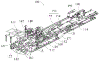
fig. 1 is a schematic structural view of a heading system according to an embodiment of the present invention;
fig. 2 is a schematic view of another perspective structure of the tunneling system of the embodiment shown in fig. 1;
fig. 3 is a partially enlarged structural schematic diagram of a part a of the tunneling system of the embodiment shown in fig. 2;
fig. 4 is a partially enlarged structural schematic diagram of a part B of the tunneling system according to the embodiment shown in fig. 2.
Wherein, the correspondence between the reference numbers and the part names in fig. 1 to 4 is:
100 tunneling system, 110 machine body, 112 machine frame, 120 cutting device, 122 cutting part, 130 supporting device, 140 bolting device, 142 bolting machine, 150 conveying device, 152 first conveyor, 154 belt conveyor, 160 stepping type walking mechanism, 162 front walking part, 1622 front sliding rail part, 1624 front lifting assembly, 1626 front driving assembly, 164 rear walking part, 1642 rear sliding rail part, 1644 rear lifting assembly, 1646 rear driving assembly, 170 transition device, 180 shoveling plate device, 182 shoveling plate part, 190 power device and 192 power part.
Detailed Description
In order that the above objects, features and advantages of the present invention can be more clearly understood, a more particular description of the invention will be rendered by reference to the appended drawings. It should be noted that the embodiments and features of the embodiments of the present application may be combined with each other without conflict.
In the following description, numerous specific details are set forth in order to provide a thorough understanding of the present invention, however, the present invention may be practiced otherwise than as specifically described herein and, therefore, the scope of the present invention is not limited by the specific embodiments disclosed below.
A ripping system 100 provided in accordance with some embodiments of the present invention is described below with reference to fig. 1-4.
As shown in fig. 1 to 4, a heading system 100 according to an embodiment of the present invention includes: a body 110; the cutting device 120, the cutting device 120 is arranged on the machine body 110 to cut the material of the roadway; a supporting device 130, wherein the supporting device 130 is arranged on the machine body 110 to support the wall surface of the roadway; the anchor device 140, the anchor device 140 is arranged on the machine body 110 to anchor the wall surface of the roadway; the transportation device 150 is connected to the machine body 110, and is used for transporting the materials cut by the cutting device 120; the step-by-step traveling mechanism 160, the step-by-step traveling mechanism 160 is disposed at the bottom of the machine body 110 and the transportation device 150 to drive the machine body 110 and the transportation device 150 to move synchronously.
Specifically, as shown in fig. 1 and 2, the tunneling system 100 includes a machine body 110, a cutting device 120, a support device 130, a bolting device 140, a transporting device 150, and a step-by-step traveling mechanism 160. Wherein, the cutting device 120 is arranged on the machine body 110 to cut the material in the roadway. The supporting device 130 is arranged on the machine body 110, and the supporting device 130 can support the wall surface of the roadway after cutting, so that materials are prevented from falling.
Further, anchor rod device 140 sets up on organism 110, and anchor rod device 140 can squeeze into the anchor rod operation to the tunnel wall after strutting, realizes consolidating the fixed operation to the wall in tunnel. The transportation device 150 is connected to the machine body 110, and is used for transporting the materials cut by the cutting device 120, that is, transporting the materials cut by the cutting device 120 from the roadway to the outside of the roadway through the transportation device 150, so as to avoid the accumulation of the materials cut by the cutting device and the influence on the cutting operation.
In addition, the stepping type traveling mechanism 160 is provided at the bottom of the machine body 110 and the transportation device 150 to drive the machine body 110 and the transportation device 150 to move synchronously, and by installing the stepping type traveling mechanism 160 at the bottom of the machine body 110 and the bottom of the transportation device 150, the machine body 110 and the transportation device 150 can be moved synchronously when the tunneling system 100 needs to be moved, so that the tunneling system 100 can be moved integrally, and the moving speed of the tunneling system 100 as a whole is increased.
The cutting device 120, the supporting device 130, the anchor rod device 140, the conveying device 150 and the stepping type travelling mechanism 160 are integrated and set to be the integrated tunneling system 100, so that the operation efficiency of the whole machine is improved, the situation that the working surface needs to be withdrawn after the operation of the cutting device 120 is completed is avoided, the operation space is provided for the supporting device 130 and the anchor rod device 140, and the operation process is complicated. The integrated system is utilized to perform centralized operation, so that the operation efficiency of the tunneling system 100 is effectively improved.
Further, the step-by-step traveling mechanism 160 is provided on the machine body 110 and the conveyor 150, respectively, instead of the crawler belt, so that the entire excavation system 100 can be moved synchronously, the entire movement speed of the excavation system 100 can be increased, and the work efficiency of the excavation system 100 can be further improved.
Specifically, the heading system 100 is provided with a machine body 110, the front end of the machine body 110 is provided with a cutting device 120, and a supporting device 130 is arranged on the cutting device 120 and can move along with the movement of the cutting device 120, and generally, when the cutting device 120 works, the supporting device 130 is folded and placed on the cutting device 120, and is opened to perform supporting work when supporting work is needed. The tunneling system 100 further includes an anchor device 140, and the anchor device 140 is disposed on the machine body 110 at the rear side of the cutting device 120, is folded and stored on the machine body 110, and can be unfolded for operation when anchor operation is required. The tunneling system 100 further includes a transportation device 150, and the transportation device 150 is connected to the machine body 110 and partially disposed below the machine body 110, so as to facilitate transportation of the cut materials. The tunneling system 100 further comprises a step-by-step traveling mechanism 160, wherein the step-by-step traveling mechanism 160 is arranged at the bottom of the machine body 110 and the transportation device 150, can adjust the machine body 110 and the transportation device 150 to move synchronously, and can drive the tunneling system 100 to move integrally when the tunneling system 100 needs to move.
Illustratively, in the operation process of the tunneling system 100, after the cutting device 120 is started, the cutting device 120 cuts the wall surface of the roadway, and the cut material is transported to the outside of the roadway through the transportation device 150. After the cutting device 120 cuts and advances a predetermined distance, the cutting device 120 stops working, the supporting device 130 is started to expand, and the wall surface of the roadway surrounding rock after cutting is supported, so that the material on the wall surface of the roadway is prevented from falling. After the supporting operation is completed, the supporting device 130 is folded and folded, the anchor rod device 140 is started to be unfolded, anchor rod operation is performed on the supported roadway surrounding rock wall surface, and the roadway surrounding rock wall surface is reinforced and fixed. After the bolting operation is completed, the tunneling system 100 needs to advance by one step to continue the cutting operation, at this time, the stepping type traveling mechanism 160 drives the machine body 110 and the transportation device 150 to move synchronously, so that the tunneling system 100 integrally advances by one step to perform the next cutting procedure operation, and the operation is repeated in such a cycle, and the tunneling system 100 needs to retreat, which is opposite to the advancing step, and will not be described here.
The cutting device 120, the supporting device 130, the anchor rod device 140, the conveying device 150 and the stepping type travelling mechanism 160 are integrated and set to be the integrated tunneling system 100, so that the operation efficiency of the whole machine is improved, and the problems that in the tunneling equipment in the tunnel operation process, the tunneling machine needs to be withdrawn from a working surface after the operation of the tunneling machine is completed to provide operation space for anchors and protection equipment and the operation process is complicated due to the fact that the tunneling machine is separately arranged from the anchor rod device, the supporting device and the conveying device in the traditional crawler type tunneling equipment in the related technology are solved. The integrated centralized operation of the tunneling system 100 is realized, and the operation efficiency of the tunneling system 100 is effectively improved.
In a specific application, the tunneling system 100 may be a stepping fast tunneling-anchoring system or a stepping parallel-operation tunneling-supporting system, which are not listed here.
In the above embodiment, further: as shown in fig. 1 and 2, the step-by-step traveling mechanism 160 includes; a front traveling part 162, the front traveling part 162 being disposed on the body 110 and located at the bottom of the body 110; the rear walking part 164, the rear walking part 164 is arranged on the transportation device 150 and is positioned at the bottom of the transportation device 150; the front traveling part 162 and the rear traveling part 164 can drive the machine body 110 and the transportation device 150 to move synchronously, so that the tunneling system 100 moves integrally.
Specifically, as shown in fig. 2, the step-by-step traveling mechanism 160 includes a front traveling part 162 and a rear traveling part 164. The front walking part 162 is disposed on the machine body 110, specifically disposed at the bottom of the machine body 110, and the machine body 110 is driven to move by the front walking part 162. Further, the rear walking portion 164 is disposed on the transportation device 150, specifically disposed at the bottom of the transportation device 150, and the transportation device 150 is driven to move by the rear walking portion 164. The front walking part 162 is arranged at the bottom of the machine body 110, and the rear walking part 164 is arranged at the bottom of the conveying device 150, so that the machine body 110 is driven by the front walking part 162 to synchronously move together with the conveying device 150 driven by the rear walking part 164, the tunneling system 100 can integrally move, and the moving speed of the tunneling system 100 is improved.
Specifically, the front traveling part 162 is arranged at the bottom of the machine body 110, the rear traveling part 164 is arranged at the bottom of the transportation device 150, and the stepping traveling mechanisms 160 are separately arranged, so that the machine body 110 and the transportation device 150 can be driven simultaneously, compared with the situation that the stepping traveling mechanisms 160 are arranged only on the machine body 110 to pull the transportation device 150 to move, the driving force provided by the split arrangement is larger, the driving control is more accurate, the moving speed of the tunneling system 100 is higher, and the working efficiency of the tunneling system 100 can be effectively improved. Meanwhile, compared with the conventional crawler-type travelling mechanism, the walking mechanism 160 has a simpler structure and lower production cost, and in the moving process of the tunneling system 100, the walking mechanism 160 is not easily surrounded by soil, so that the walking mechanism is easy to clean and maintain, and the use safety and reliability of the walking mechanism 160 are effectively improved.
In any of the above embodiments, further, as shown in fig. 1, 2 and 3, the front walking portion 162 includes: a front rail part 1622, the front rail part 1622 movably connected to the bottom of the machine body 110; one end of the front lifting assembly 1624 stretches relative to the other end, one end of the front lifting assembly 1624 is connected with the machine body 110, the other end of the front lifting assembly 1624 is movably connected with the front sliding rail portion 1622, and the front lifting assembly 1624 is switched between an extending state and a contracting state to drive the front sliding rail portion 1622 to contact with or separate from the supporting surface; and a front driving assembly 1626, wherein one end of the front driving assembly 1626 is connected to the front lifting assembly 1624, the other end of the front driving assembly 1626 is hinged to the front rail portion 1622, the front driving assembly 1626 drives the body 110 to move relative to the front rail portion 1622 when the front lifting assembly 1624 is in the extended state, and the front driving assembly 1626 drives the front rail portion 1622 to move relative to the body 110 when the front lifting assembly 1624 is in the retracted state.
Specifically, as shown in fig. 3, the front walking portion 162 includes a front rail portion 1622, a front lift assembly 1624, and a front drive assembly 1626. Wherein, through preceding lift assembly 1624 one end and organism 110 connection, the other end and preceding slide rail portion 1622 swing joint, preceding lift assembly 1624 is at flexible in-process, can drive preceding slide rail portion 1622 and ground contact or separation, and then slide rail portion 1622 contact ground before promoting when lift assembly 1624 stretches out the state in the front, realizes supporting organism 110, slide rail portion 1622 and ground separation before the pulling when lift assembly 1624 shrink state in the front.
Further, one end of the front driving assembly 1626 is connected to the front lifting assembly 1624, and the other end of the front driving assembly 1626 is hinged to the front sliding rail portion 1622, so that the front lifting assembly 1624 is driven by the front driving assembly 1626 to move the machine body 110 and the front sliding rail portion 1622 relative to each other, thereby realizing the forward movement or the backward movement of the machine body 110.
Specifically, when the front lifting assembly 1624 is in a protruding state, the front lifting assembly 1624 pushes the front rail portion 1622 to protrude to contact with the ground, and the front driving assembly 1626 drives the machine body 110 to move relative to the front rail portion 1622, it can be understood that since the front rail portion 1622 does not touch the ground at this time, the machine body 110 can move back and forth relative to the ground under the driving of the front driving assembly 1626, that is, the movement of the machine body 110 relative to the front rail portion 1622 means that the machine body 110 moves forward or backward relative to the front rail portion 1622, that is, the ground, so as to achieve the forward or backward movement of the machine body 110.
When the front lifting assembly 1624 is in a retracted state, the front lifting assembly 1624 pulls the front sliding rail portion 1622 to retract to be separated from the ground, the front driving assembly 1626 drives the front sliding rail portion 1622 to move relative to the machine body 110, it can be understood that since the front sliding rail portion 1622 does not contact the ground at this time, a part of the structure of the machine body 110 contacts the ground, that is, the machine body 110 does not contact the ground at this time, the front sliding rail portion 1622 is suspended, the front sliding rail portion 1622 can move forward or backward relative to the machine body 110 under the driving of the front driving assembly 1626, so that the reset between the front sliding rail portion 1622 and the machine body 110 is realized, that the front sliding rail portion 1622 retracts to the lower side of the machine body 110, and the initial state of the front sliding rail portion 1622 and the machine body 110 is restored. Through mutually supporting between preceding lift subassembly 1624, preceding slide rail portion 1622 and the preceding drive assembly 1626, walking portion 162 drives organism 110 back-and-forth movement before realizing, replaces the track through preceding walking portion 162 promptly to drive organism 110 walking, is driving organism 110 removal in-process like this, because preceding walking portion 162 ground connection area is big, and organism 110 ground connection is littleer than pressing, avoids ground to be destroyed, improves organism 110's walking speed. And the front traveling part 162 is simple in structure and easy to clean and maintain.
In particular applications, the front lift assembly 1624 and the front drive assembly 1626 may be configured as hydraulic or pneumatic cylinders, among others, not listed herein.
In any of the above embodiments, further, as shown in fig. 1, 2 and 4, the rear walking portion 164 includes: a rear slide rail portion 1642, the rear slide rail portion 1642 being movably connected to the bottom of the transportation device 150; the rear lifting assembly 1644 is used for driving one end of the rear lifting assembly 1644 to stretch relative to the other end, one end of the rear lifting assembly 1644 is connected with the conveying device 150, the other end of the rear lifting assembly 1644 is movably connected with the rear sliding rail portion 1642, and the rear lifting assembly 1644 is switched between an extending state and a contracting state to drive the rear sliding rail portion 1642 to be in contact with or separated from the supporting surface; and a rear driving assembly 1646, wherein one end of the rear driving assembly 1646 is connected with the rear lifting assembly 1644, the other end of the rear driving assembly 1646 is hinged with the rear slide rail portion 1642, the rear driving assembly 1646 drives the transportation device 150 to move relative to the rear slide rail portion 1642 when the rear lifting assembly 1644 is in an extending state, and the rear driving assembly 1646 drives the rear slide rail portion 1642 to move relative to the transportation device 150 when the rear lifting assembly 1644 is in a contracting state.
Specifically, as shown in fig. 4, the rear traveling part 164 includes a rear rail part 1642, a rear lift assembly 1644, and a rear driving assembly 1646. Wherein, be connected with conveyer 150 through back lifting unit 1644 one end, the other end and back slide rail portion 1642 swing joint, back lifting unit 1644 is at flexible in-process, can drive back slide rail portion 1642 and ground contact or separation, and then promotes back slide rail portion 1642 contact ground when back lifting unit 1644 stretches out the state, realizes supporting conveyer 150, draws back slide rail portion 1642 and ground separation when back lifting unit 1644 shrink state.
Further, one end through setting up back drive assembly 1646 is connected with back lifting unit 1644, and back drive assembly 1646's the other end is articulated with back slide rail portion 1642 to through back drive assembly 1646 drive back lifting unit 1644 drive and remove each other between conveyer 150 and the back slide rail portion 1642, realize conveyer 150's forward movement or backward movement.
Specifically, when the rear lifting assembly 1644 is in an extended state, the rear lifting assembly 1644 pushes the rear slide rail portion 1642 to extend to contact with the ground, and the rear driving assembly 1646 drives the transportation device 150 to move relative to the rear slide rail portion 1642, it can be understood that, since the rear slide rail portion 1642 is not in contact with the ground at this time, the transportation device 150 can move back and forth relative to the ground under the driving of the rear driving assembly 1646, that is, the transportation device 150 moves relative to the rear slide rail portion 1642 means that the transportation device 150 moves forward or backward relative to the rear slide rail portion 1642, that is, the ground, so as to realize the forward or backward movement of the transportation device 150.
When the rear lifting assembly 1644 is in a retracted state, the rear lifting assembly 1644 pulls the rear slide rail portion 1642 to retract and separate from the ground, the rear driving assembly 1646 drives the rear slide rail portion 1642 to move relative to the transportation device 150, it can be understood that, at this time, the rear slide rail portion 1642 does not contact the ground, a part of the structure of the transportation device 150 contacts the ground, that is, the transportation device 150 does not contact the ground, the rear slide rail portion 1642 is suspended, the rear slide rail portion 1642 can move forward or backward relative to the transportation device 150 under the driving of the rear driving assembly 1646, so that the return between the rear slide rail portion 1642 and the transportation device 150 is realized, that the rear slide rail portion 1642 is retracted below the transportation device 150, and is restored to the initial state of the rear slide rail portion 1642 and the transportation device 150. Through the back lifting unit 1644, mutually supporting between back slide rail portion 1642 and the back drive assembly 1646, realize that back walking portion 164 drives conveyer 150 back-and-forth movement, replace the walking of track drive conveyer 150 through back walking portion 164 promptly, drive conveyer 150 like this and remove the in-process, because back walking portion 164 area of grounding is big, conveyer 150 ground connection specific pressure is littleer, avoids ground to be destroyed, improves conveyer 150's walking speed. And the rear traveling part 164 is simple in structure and easy to clean and maintain.
In particular applications, rear lift assembly 1644 and rear drive assembly 1646 may be configured as hydraulic or pneumatic cylinders or the like, and front lift assembly 1624 and rear lift assembly 1644 may be configured identically.
In any of the above embodiments, further, as shown in fig. 1 and fig. 2, the front lifting assembly 1624 and the rear lifting assembly 1644 are lifted synchronously to drive the machine body 110 to lift synchronously with the transportation device 150; the front drive assembly 1626 and the rear drive assembly 1646 are driven in synchronization to drive the body 110 and the transporter 150 in synchronization to move the tunneling system 100 as a whole.
Specifically, as shown in fig. 2, the front traveling part 162 is provided at the bottom of the machine body 110, the rear traveling part 164 is provided at the bottom of the transportation device 150, and the front traveling part 162 and the rear traveling part 164 are identically configured. In this way, the front lifting assembly 1624 and the rear lifting assembly 1644 are lifted synchronously to drive the machine body 110 and the transportation device 150 to lift synchronously. Further, the front driving assembly 1626 and the rear driving assembly 1646 are driven synchronously to drive the machine body 110 and the transportation device 150 to move synchronously, so that the tunneling system 100 can move integrally, and the front traveling part 162 and the rear traveling part 164 are separately arranged on the machine body 110 and the transportation device 150, so that the driving force provided to the machine body 110 and the transportation device 150 by the separate arrangement is larger, the driving control of the machine body 110 and the transportation device 150 is more accurate, the tunneling system 100 moves at a higher speed, and the operating efficiency of the tunneling system 100 can be effectively improved.
Illustratively, when the tunneling system 100 needs to walk forward, the front lifting assembly 1624 and the rear lifting assembly 1644 are simultaneously extended to respectively push the front sliding rail portion 1622 and the rear sliding rail portion 1642 to fall into contact with the ground, and the machine body 110 and the transportation device 150 are simultaneously supported by the front sliding rail portion 1622 and the rear sliding rail portion 1642, at this time, the front sliding rail portion 1622 and the rear sliding rail portion 1642 are not contacted with the ground, and then the front lifting assembly 1624, the machine body 110, the rear lifting assembly 1644 and the transportation device 150 are simultaneously pushed by the front driving assembly 1626 and the rear driving assembly 1646 to simultaneously move forward relative to the ground, that is, the machine body 110 and the transportation device 150 are simultaneously pushed by the front driving assembly 1626 and the rear driving assembly 1646 to simultaneously move relative to the front sliding rail portion 1622 and the rear sliding rail portion 1642, so that the movement of the machine body 110 and the transportation device 150 relative to the ground by one stroke is completed. After the machine body 110 and the transportation device 150 move for a stroke, the front lifting assembly 1624 and the rear lifting assembly 1644 contract simultaneously, and pull the front sliding rail part 1622 and the rear sliding rail part 1642 to retract simultaneously, that is, the machine body 110 and the transportation device 150 touch the ground and are not moved at the moment, the front driving assembly 1626 and the rear driving assembly 1646 pull the front sliding rail part 1622 and the rear sliding rail part 1642 to move forwards for a stroke simultaneously, that is, the reset between the front sliding rail part 1622 and the rear sliding rail part 1642 relative to the machine body 110 and the transportation device 150 is completed, at the moment, a forward stroke of the tunneling system 100 is completed, and the tunneling system 100 advances for a step stroke.
When the tunneling system 100 needs to move backwards, the front driving assembly 1626 and the rear driving assembly 1646 extend out simultaneously, the front sliding rail part 1622 and the rear sliding rail part 1642 are pushed to move backwards by a step stroke relative to the machine body 110 and the transportation device 150 simultaneously, the front lifting assembly 1624 and the rear lifting assembly 1644 are started to extend out simultaneously, the front sliding rail part 1622 and the rear sliding rail part 1642 are pushed to fall down to be in contact with the ground simultaneously, the machine body 110 and the transportation device 150 are supported up simultaneously through the front sliding rail part 1622 and the rear sliding rail part 1642, the machine body 110 and the transportation device 150 are pulled simultaneously by the front driving assembly 1626 and the rear driving assembly 1646 to move backwards relative to the ground simultaneously, and the movement that the whole machine body 110 and the transportation device 150 move backwards by a stroke relative to the ground is completed. And then the front lifting assembly 1624 and the rear lifting assembly 1644 contract and pull the front sliding rail part 1622 and the rear sliding rail part 1642 to rise and separate from the ground at the same time, so that the backward movement of one step travel of the whole tunneling system 100 is completed. It should be noted that the initial state is a state where the front lifting assembly 1624 is in a retracted state and the front rail portion 1622 is retracted to the lower side of the machine body 110 in a suspended manner, and a state where the rear lifting assembly 1644 is in a retracted state and the rear rail portion 1642 is retracted to the lower side of the belt conveyor 154 in a suspended manner.
In any of the above embodiments, further, as shown in fig. 1 and 2, the front walking part 162 may further include: a front rail part 1622, the front rail part 1622 movably connected to the bottom of the machine body 110; one end of the front lifting assembly 1624 stretches relative to the other end, one end of the front lifting assembly 1624 is connected with the machine body 110, the other end of the front lifting assembly 1624 is movably connected with the front sliding rail part 1622, and the front lifting assembly 1624 is switched between an extending state and a contracting state so as to drive the front sliding rail part 1622 to be in contact with or separated from the supporting surface; the front driving assembly 1626 is connected to the front lifting assembly 1624 at one end of the front driving assembly 1626, the front sliding rail portion 1622 is hinged to the other end of the front driving assembly 1626, the front driving assembly 1626 drives the body 110 to move relative to the front sliding rail portion 1622 when the front lifting assembly 1624 is in the extending state, and the front driving assembly 1626 drives the front sliding rail portion 1622 to move relative to the body 110 when the front lifting assembly 1624 is in the retracting state.
The rear walking portion 164 includes: a rear slide rail portion 1642, the rear slide rail portion 1642 being movably connected to the bottom of the transportation device 150; back lifting unit 1644, back lifting unit 1644's one end is flexible for the other end, and back lifting unit 1644's one end is connected with conveyer 150, and back lifting unit 1644's the other end and back slide rail portion 1642 swing joint, back lifting unit 1644 switch between the state of stretching out and the shrink state to drive back slide rail portion 1642 and holding surface contact or separation.
Specifically, as shown in fig. 2, the front traveling part 162 is disposed at the bottom of the machine body 110, the rear traveling part 164 is disposed at the bottom of the transportation device 150, and the rear driving assembly 1646 is not disposed in the structural arrangement of the rear traveling part 164, and only the front lifting assembly 1624 and the rear lifting assembly 1644 are used for synchronously lifting, so that the machine body 110 and the transportation device 150 are driven to synchronously lift. Further, the front driving assembly 1626 is utilized to drive the machine body 110 to move, and the transportation device 150 is pulled by the machine body 110 to move synchronously, so that the tunneling system 100 can move integrally, the arrangement can reduce the arrangement of the rear driving assembly 1646, the arrangement number of integral structural components and the production cost. Meanwhile, the aim of improving the moving speed of the tunneling system 100 and further improving the operation efficiency of the tunneling system 100 can be achieved.
In any of the above embodiments, further, as shown in fig. 1 and fig. 2, the method further includes: one end of the transition device 170 is connected to the front walking part 162, and the other end of the transition device 170 is connected to the rear walking part 164, so that the front walking part 162 drives the machine body 110 to move synchronously with the rear walking part 164 driving the transportation device 150.
Specifically, as shown in fig. 1 and 2, the ripping system 100 further includes a transition device 170. The transition device 170 is connected between the front traveling part 162 and the rear traveling part 164, and is used for connecting the front traveling part 162 and the rear traveling part 164, so that the front traveling part 162 drives the machine body 110, and the rear traveling part 164 drives the transportation device 150 to move synchronously, thereby realizing the overall movement of the tunneling system 100.
Specifically, by arranging that one end of the transition device 170 is connected to the front traveling part 162 and the other end of the transition device 170 is connected to the rear traveling part 164, the front traveling part 162 and the rear traveling part 164 can be tightly connected together, when the tunneling system 100 moves, the front traveling part 162 can drive the machine body 110 and the rear traveling part 164 to drive the transportation device 150 to move synchronously, and the integrity and consistency of the movement of the tunneling system 100 are improved.
In a specific application, the transition device 170 may be configured as a transition plate, which has a simple structure, is convenient to mount and dismount, and is easy to produce and process.
In any of the above embodiments, further, as shown in fig. 1 and 2, the transition device 170 is movably connected between the front walking portion 162 and the rear walking portion 164; or transition device 170 is fixedly coupled between forward walking portion 162 and rearward walking portion 164.
Specifically, by arranging the transition device 170 to be movably connected between the front walking part 162 and the rear walking part 164, in the moving process of the tunneling system 100, the position relationship between the front walking part 162 and the rear walking part 164 can be flexibly adjusted, excessive stress concentration between the front walking part 162 and the rear walking part 164 is avoided, and the pushing force and the pulling force generated in the moving process of the front walking part 162 and the rear walking part 164 are relieved.
In a specific application, the transition device 170 may be hinged between the front walking part 162 and the rear walking part 164, and the hinge is easy to disassemble, assemble, replace and maintain.
By arranging the transition device 170 to be fixedly connected between the front walking part 162 and the rear walking part 164, in the moving process of the tunneling system 100, the position relation between the front walking part 162 and the rear walking part 164 can be fixed, the front walking part 162 and the rear walking part 164 are prevented from being mutually staggered in the moving process, the synchronous motion consistency between the front walking part 162 and the rear walking part 164 is kept, and the moving integrity and the high efficiency of the tunneling system 100 are ensured.
In specific application, the transition device 170 can be welded between the front walking part 162 and the rear walking part 164 in a welding manner, so that the welding manner is easy to operate, not easy to damage in the using process and easy to maintain.
In any of the above embodiments, further, as shown in fig. 1 and fig. 2, further comprising; the blade device 180 is disposed on the body 110 and below the cutting device 120, so as to collect the material cut by the cutting device 120.
Specifically, as shown in fig. 2, the ripping system 100 also includes a blade arrangement 180. The shovel plate device 180 is disposed on the machine body 110 and below the cutting device 120, so as to collect the materials cut by the cutting device 120.
Specifically, the shovel plate device 180 is arranged on the machine body 110, can move together with the machine body 110, and is located below the cutting device 120, so that when the cutting device 120 performs cutting operation, materials dropped during cutting can fall into the shovel plate device 180, the materials are collected and discharged to the transporting device 150 through the shovel plate device 180, the materials are transported to the outside of a roadway through the transporting device 150, the materials prevented from being cut are prevented from being stacked, the operation of the tunneling system 100 is influenced, and the integrated operation of cutting, supporting, anchoring and transporting is realized.
In any of the above embodiments, further, as shown in fig. 1 and fig. 2, further comprising; and the power device 190 is arranged on the conveying device 150 and is used for providing power output for the tunneling system 100.
Specifically, as shown in fig. 1 and 2, the tunneling system 100 further includes a power plant 190. The power device 190 is arranged on the transportation device 150, can move along with the transportation device 150, and is used for providing power output for the tunneling system 100 and ensuring the stability of the power output of the tunneling system 100.
In any of the above embodiments, further, as shown in fig. 1 and fig. 2, the body 110 includes a frame 112, and the front walking part 162 is disposed at the bottom of the frame 112; the cutting device 120 comprises a cutting part 122, the cutting part 122 is arranged on the frame 112, and the supporting device 130 is arranged on the cutting part 122; and the bolting assembly 140 includes a bolter 142, the bolter 142 being disposed on the frame 112; the shovel plate device 180 comprises a shovel plate part 182, and the shovel plate part 182 is arranged on the rack 112 and is positioned below the cutting part 122; the transportation device 150 comprises a first transportation machine 152 and a belt conveyer 154, one end of the first transportation machine 152 is connected with the shovel plate part 182, the other end of the first transportation machine 152 is connected with the belt conveyer 154, and the rear walking part 164 is arranged at the bottom of the belt conveyer 154; and the power device 190 comprises a power part 192, the power part 192 is arranged on the belt conveyer 154; the front traveling part 162 drives the frame 112, and the rear traveling part 164 drives the belt conveyor 154 to move synchronously, so that the tunneling system 100 moves integrally.
Specifically, as shown in fig. 1 and 2, the machine body 110 includes a frame 112, the front traveling part 162 is disposed at the bottom of the frame 112, and the frame 112 is disposed on the machine body 110, so that the cutting device 120, the supporting device 130, the bolting device 140 and the transportation device 150 are mounted on the frame 112, and thus, various tunneling operation components are mounted together in a centralized manner, which is beneficial to the centralized integration of multiple components and the integrated arrangement.
Further, the cutting device 120 includes a cutting portion 122, the cutting portion 122 is disposed on the frame 112, and the supporting device 130 is disposed on the cutting portion 122, so that the cutting portion 122 and the supporting device 130 move together, and the position of the supporting device 130 during supporting operation can be adjusted by adjusting the cutting portion 122, which is more convenient to operate. Meanwhile, the multiple components are arranged in a centralized manner, so that the occupied space of the components can be reduced, and the miniaturization design of the tunneling system 100 is facilitated.
Further, the bolting device 140 comprises a bolting machine 142, the bolting machine 142 is arranged on the rack 112, the bolting machine 142 can move along with the rack 112, after the supporting operation is completed, the anchoring operation can be rapidly carried out, the operation efficiency is improved, meanwhile, the bolting device 140 is arranged on the rack 112, so that various tunneling operation components are installed together in a centralized mode, the centralized integration of multiple components is facilitated, and the integrated setting is realized.
Further, the shovel plate unit 180 includes a shovel plate 182, the shovel plate 182 is disposed on the rack 112 and located below the cutting unit 122, the shovel plate 182 is disposed on the rack 112, can move along with the rack 112 and located below the cutting unit 122, so that when the cutting unit 122 performs cutting operation, materials dropped by cutting can fall into the shovel plate 182, and are collected and discharged to the transporting unit 150 through the shovel plate 182, and the materials are transported to the outside of the roadway through the transporting unit 150, so that the accumulation of the materials dropped by cutting is avoided, the operation of the tunneling system 100 is affected, and the integrated operations of cutting, supporting, anchoring and transporting are realized.
Further, the transportation device 150 includes a first conveyor 152 and a belt conveyor 154, one end of the first conveyor 152 is connected to the shovel portion 182, the other end of the first conveyor 152 is connected to the belt conveyor 154, and the rear traveling portion 164 is disposed at the bottom of the belt conveyor 154. Connect on shovel board portion 182 through first conveyer 152, realized the quick collection and the transportation to the cut material, link to each other with band conveyer 154 through first conveyer 152, realized that the material that will roll out conveys outside the tunnel through band conveyer 154. By providing the transport apparatus 150 including the first conveyor 152 and the belt conveyor 154, the second conveyor is omitted, the intermediate transfer distance of the material is reduced, the number of component parts is reduced, the structure is optimized, and the production cost is reduced. Further, by arranging the first conveyor 152 and the belt conveyor 154 on the frame 112, the centralized integration and integration of a plurality of components are realized, and then the cutting, supporting, bolting and transferring integrated operation is realized.
Further, the power device 190 comprises a power part 192, and the power part 192 is arranged on the belt conveyor 154, so that the stability of power output of the tunneling system 100 is guaranteed, and meanwhile, the centralized integration and integration arrangement of a plurality of components is realized. In addition, the front traveling part 162 drives the frame 112 and the rear traveling part 164 drives the belt conveyor 154 to move synchronously, so that the tunneling system 100 moves integrally, and the moving speed and the operation efficiency of the tunneling system 100 are improved.
Specifically, the tunneling system 100 is provided with a rack 112, a cutting part 122 is mounted at the front end of the rack 112, a supporting device 130 is mounted on the cutting part 122, a bolting device 140 is mounted on the rack 112 and located at the rear side of the cutting part 122, a shovel plate part 182 is mounted on the rack 112 and located below the cutting part 122, a front walking part 162 and a first conveyor 152 are mounted on the rack 112, a belt conveyor 154 is connected on the first conveyor 152 and located at the rear part of the rack 112, a power part 192 is mounted above the belt conveyor 154, and a rear walking part 164 is mounted at the bottom of the belt conveyor 154, so that the centralized integration and integration setting of a plurality of parts is realized, and further the integrated operation of cutting, supporting, bolting and transferring is realized.
Illustratively, in the operation process of the tunneling system 100, after the cutting device 120 is started in the operation process of the tunneling system 100, the cutting part 122 cuts the wall surface of the roadway, the cut material falls into the shovel part 182, the material is discharged into the first conveyor 152 through the rotation of the star wheel in the shovel part 182, and the first conveyor 152 transports the material to the belt conveyor 154 and transports the material to the outside of the roadway through the belt conveyor 154. After the cutting part 122 cuts and advances a preset distance, the cutting device 120 stops working, the supporting device 130 is started, and the supporting device 130 is unfolded and lifted to support the wall surface of the roadway surrounding rock after cutting, so that the material on the wall surface of the roadway is prevented from falling. After strutting the operation and accomplishing, supporting device 130 is folded to be received and is put, starts bolting device 140 and expandes the operation, and roofbolter 142 stretches out the assigned position and beats the stock operation to strutting the tunnel country rock wall face of accomplishing, realizes consolidating fixedly to tunnel country rock wall face. After the operation of the jumbolter 142 is completed, the tunneling system 100 needs to advance one step to continue the cutting operation, and at this time, the front walking part 162 of the step-type walking mechanism 160 drives the machine body 110 and the rear walking part 164 to drive the belt conveyor 154 to move synchronously, so that the tunneling system 100 integrally advances one step to perform the next cutting operation, and the operation is repeated in a circulating manner.
The cutting device 120, the supporting device 130, the anchor rod device 140, the shovel plate device 180, the power device 190, the conveying device 150 and the stepping type traveling mechanism 160 are integrated to form the integrated tunneling system 100, so that the working efficiency of the whole machine is improved, and the problems that in the traditional crawler type tunneling equipment in the related technology, a tunneling machine needs to be separated from a working surface to provide working space for anchoring and protecting equipment and the working procedure is complicated due to the fact that the tunneling machine, the anchor rod device, the supporting device and the conveying device are arranged separately in the tunneling equipment in the tunneling operation process. The integrated centralized operation of the tunneling system 100 is realized, and the operation efficiency of the tunneling system 100 is effectively improved.
In the description of the present invention, the terms "plurality" or "a plurality" refer to two or more, and unless otherwise specifically limited, the terms "upper", "lower", and the like indicate orientations or positional relationships based on the orientations or positional relationships shown in the drawings, and are merely for convenience in describing the present invention and simplifying the description, but do not indicate or imply that the referred device or element must have a specific orientation, be constructed in a specific orientation, and be operated, and thus should not be construed as limiting the present invention; the terms "connected", "mounted", "fixed", and the like are to be construed broadly and may include, for example, fixed connections, detachable connections, or integral connections; may be directly connected or indirectly connected through an intermediate. The specific meanings of the above terms in the present invention can be understood by those skilled in the art according to specific situations.
In the description herein, the description of the terms "one embodiment," "some embodiments," "specific embodiments," etc., means that a particular feature, structure, material, or characteristic described in connection with the embodiment or example is included in at least one embodiment or example of the invention. In this specification, the schematic representations of the terms used above do not necessarily refer to the same embodiment or example. Furthermore, the particular features, structures, materials, or characteristics described may be combined in any suitable manner in any one or more embodiments or examples.
The present invention has been described in terms of the preferred embodiment, and it is not intended to be limited to the embodiment. Any modification, equivalent replacement, or improvement made within the spirit and principle of the present invention should be included in the protection scope of the present invention.
Claims (10)
1. A tunneling system, comprising:
a body;
the cutting device is arranged on the machine body and is used for cutting the materials of the roadway;
the supporting device is arranged on the machine body and used for supporting the wall surface of the roadway;
the anchor rod device is arranged on the machine body so as to anchor the wall surface of the roadway;
the transportation device is connected to the machine body and is used for transporting the materials cut by the cutting device;
the stepping type travelling mechanism is arranged at the bottom of the machine body and the conveying device to drive the machine body and the conveying device to synchronously move.
2. The tunneling system of claim 1, wherein the step-by-step travel mechanism comprises;
the front walking part is arranged on the machine body and is positioned at the bottom of the machine body;
the rear walking part is arranged on the conveying device and is positioned at the bottom of the conveying device;
the front walking part and the rear walking part can drive the machine body and the conveying device to move synchronously, so that the tunneling system moves integrally.
3. The tunneling system of claim 2, wherein the front traveling part comprises:
the front sliding rail part is movably connected to the bottom of the machine body;
one end of the front lifting assembly stretches relative to the other end of the front lifting assembly, one end of the front lifting assembly is connected with the machine body, the other end of the front lifting assembly is movably connected with the front sliding rail part, and the front lifting assembly is switched between an extending state and a contracting state to drive the front sliding rail part to be in contact with or separated from the supporting surface;
the front driving assembly drives the machine body to move relative to the front sliding rail part when the front lifting assembly is in the contraction state, and drives the front sliding rail part to move relative to the machine body when the front lifting assembly is in the extension state.
4. The tunneling system according to claim 3, wherein the rear traveling part comprises:
the rear sliding rail part is movably connected to the bottom of the transportation device;
one end of the rear lifting assembly stretches relative to the other end of the rear lifting assembly, one end of the rear lifting assembly is connected with the conveying device, the other end of the rear lifting assembly is movably connected with the rear sliding rail part, and the rear lifting assembly is switched between the extending state and the contracting state to drive the rear sliding rail part to be in contact with or separated from the supporting surface;
the rear driving assembly drives the transportation device to move relative to the rear sliding rail part under the extending state, and drives the rear sliding rail part to move relative to the transportation device under the contracting state.
5. The tunneling system of claim 4,
the front lifting assembly and the rear lifting assembly synchronously lift to drive the machine body and the transportation device to synchronously lift;
the front driving assembly and the rear driving assembly are driven synchronously to drive the machine body and the conveying device to move synchronously, so that the tunneling system moves integrally.
6. The tunneling system of claim 2, further comprising:
and one end of the transition device is connected with the front walking part, and the other end of the transition device is connected with the rear walking part, so that the front walking part drives the machine body and the rear walking part drives the transportation device to synchronously move.
7. The tunneling system according to claim 6,
the transition device is movably connected between the front walking part and the rear walking part; or
The transition device is fixedly connected between the front walking part and the rear walking part.
8. The tunneling system according to any one of claims 2-7, further comprising;
and the shovel plate device is arranged on the machine body and is positioned below the cutting device so as to collect the materials cut by the cutting device.
9. The tunneling system of claim 8, further comprising;
and the power device is arranged on the conveying device and is used for providing power output for the tunneling system.
10. The tunneling system according to claim 9, wherein the machine body includes a frame, and the front traveling part is provided at a bottom of the frame; and
the cutting device comprises a cutting part, the cutting part is arranged on the rack, and the supporting device is arranged on the cutting part; and
the anchor rod device comprises an anchor rod drilling machine, and the anchor rod drilling machine is arranged on the rack; and
the shovel plate device comprises a shovel plate part, and the shovel plate part is arranged on the rack and is positioned below the cutting part; and
the conveying device comprises a first conveyor and a belt conveyor, one end of the first conveyor is connected with the shovel plate part, the other end of the first conveyor is connected with the belt conveyor, and the rear walking part is arranged at the bottom of the belt conveyor; and
the power device comprises a power part, and the power part is arranged on the belt conveyor;
the front walking part drives the rack, and the front walking part and the rear walking part drive the belt conveyor to move synchronously, so that the tunneling system moves integrally.
Priority Applications (1)
| Application Number | Priority Date | Filing Date | Title |
|---|---|---|---|
| CN202310006826.8A CN115680693A (en) | 2023-01-04 | 2023-01-04 | Tunneling system |
Applications Claiming Priority (1)
| Application Number | Priority Date | Filing Date | Title |
|---|---|---|---|
| CN202310006826.8A CN115680693A (en) | 2023-01-04 | 2023-01-04 | Tunneling system |
Publications (1)
| Publication Number | Publication Date |
|---|---|
| CN115680693A true CN115680693A (en) | 2023-02-03 |
Family
ID=85057366
Family Applications (1)
| Application Number | Title | Priority Date | Filing Date |
|---|---|---|---|
| CN202310006826.8A Pending CN115680693A (en) | 2023-01-04 | 2023-01-04 | Tunneling system |
Country Status (1)
| Country | Link |
|---|---|
| CN (1) | CN115680693A (en) |
Citations (3)
| Publication number | Priority date | Publication date | Assignee | Title |
|---|---|---|---|---|
| CN102606153A (en) * | 2012-04-06 | 2012-07-25 | 中铁隧道装备制造有限公司 | Fully sealed coal roadway tunneling and anchoring synchronous machine |
| CN206448809U (en) * | 2016-12-28 | 2017-08-29 | 中国煤炭科工集团太原研究院有限公司 | Pick, branch, anchor, drill integrated fully-mechanized digging machine |
| CN115535107A (en) * | 2022-12-02 | 2022-12-30 | 三一重型装备有限公司 | Traveling mechanism and engineering machine |
-
2023
- 2023-01-04 CN CN202310006826.8A patent/CN115680693A/en active Pending
Patent Citations (3)
| Publication number | Priority date | Publication date | Assignee | Title |
|---|---|---|---|---|
| CN102606153A (en) * | 2012-04-06 | 2012-07-25 | 中铁隧道装备制造有限公司 | Fully sealed coal roadway tunneling and anchoring synchronous machine |
| CN206448809U (en) * | 2016-12-28 | 2017-08-29 | 中国煤炭科工集团太原研究院有限公司 | Pick, branch, anchor, drill integrated fully-mechanized digging machine |
| CN115535107A (en) * | 2022-12-02 | 2022-12-30 | 三一重型装备有限公司 | Traveling mechanism and engineering machine |
Similar Documents
| Publication | Publication Date | Title |
|---|---|---|
| RU2123600C1 (en) | Method and device for continuous mining of aggregate material from seam | |
| US5232269A (en) | Launch vehicle for continuous mining apparatus | |
| CN111140245B (en) | Intelligent tunnel digging and supporting machine and method for rapidly forming tunnel | |
| CN212049150U (en) | Self-moving tail of large-stroke belt conveyor | |
| EP0414753B1 (en) | Shuffling quadrishoe tunnel boring machine | |
| AU644257B2 (en) | Launch vehicle for continuous mining apparatus | |
| CN115680693A (en) | Tunneling system | |
| CN111535806B (en) | Coal mining system | |
| CN109026050A (en) | A kind of anchor combined unit of fully mechanized mining formula pick branch and its an application method | |
| CN115711126A (en) | Quick tunneling system suitable for coal roadway or half-coal rock roadway | |
| EP0231655B1 (en) | Shield advancing excavator | |
| CN217925862U (en) | Shovel plate and roadway operation equipment | |
| CN111720133B (en) | Supporting device and shield tunneling equipment | |
| CN111456751A (en) | Tunneling and supporting integrated machine and using method | |
| CN219366080U (en) | Double-pushing end support special for gob-side entry retaining | |
| CN219101386U (en) | Anchor rod trolley | |
| CN210768752U (en) | Tunneling system with front tunneling part and rear anchoring part | |
| CN111255496B (en) | Coal pillar auxiliary type mining advanced temporary support device and using method thereof | |
| CN212154775U (en) | Tunneling and supporting integrated machine | |
| CN115369915B (en) | Tunneling supporting device for comprehensive pipe rack and operation method thereof | |
| CN214787382U (en) | Open-type TBM propulsion system | |
| CN219241964U (en) | Filling integral top beam combined hydraulic support | |
| US4415295A (en) | Mineral mining installations | |
| CN220702244U (en) | Retractable belt is from moving tail | |
| CN87212109U (en) | Muti-function walking type loader |
Legal Events
| Date | Code | Title | Description |
|---|---|---|---|
| PB01 | Publication | ||
| PB01 | Publication | ||
| SE01 | Entry into force of request for substantive examination | ||
| SE01 | Entry into force of request for substantive examination |